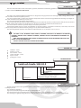
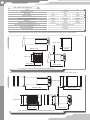
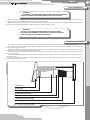
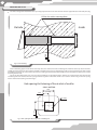
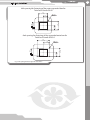
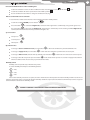
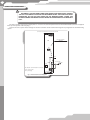
1
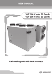
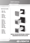
USER’S MANUAL
TwinFresh Comfo SA-50
TwinFresh Comfo SA-50-2
TwinFresh Comfo SA1-50
TwinFresh Comfo SA1-50-2
SINGLE-ROOM REVERSIBLE VENTILATOR
2
Content
Introduction
Use
Delivery set
Designation key
Technical parameters
Safety requirements
Design and operating logic
Mounting and set-up
Unit control
Connection to power mains
Maintenance
Storage and transportation rules
Manufacturing warranty
Acceptance certificate
Connection certificate
Warranty card
3
3
3
3
3
5
5
6
8
10
11
11
11
12
12
12
3
TwinFresh Comfo SА-50
INTRODUCTION
This user’s manual includes technical description, operation, installation and mounting guidelines, technical data for the single-room
reversible ventilator TwinFresh Comfo SA-50.
USE
The single-room ventilator TwinFresh Comfo SA-50 is designed to arrange permanent air exchange in flats, cottages, offices, hotels,
cafes and other residential and public premises.
The unit is equipped with a ceramic heat exchanger that provides extract air thermal energy utilization for warming up of supply air.
The total unit heat recovery efficiency reaches 91%.
The unit is designed for through-the-wall mounting.
The unit telescopic structure makes it suitable for installation in the walls from 250 mm (9 13/16’’) up to 470 mm (18 7/16”) for the unit
TwinFresh Comfo SA-50 and from 120 mm (4 3/4’’) up to 470 mm (18 1/2”) for the unit TwinFresh Comfo SA-50-2.
The unit is rated for continuous operation always connected to power mains.
Transported medium must not contain any flammable or explosive mixtures, evaporation of chemicals, coarse dust, soot and oil
particles, sticky substances, fibrous materials, pathogens or any other harmful substances.
The unit is designed for operation at the ambient temperature from -20 °C (-4°F) up to +50 °C (+122 °F).
The unit is not intended to be used by children, physically or mentally disabled
persons, persons with sensory disorder, persons with no appropriate experience or
expertise.
Only qualified experts are allowed to operate the unit after appropriate instruction
about its use and operation.
Install the unit to be out of reach of children.
DELIVERY SET
ventilator - 1 item;
fasteners - 1 item;
user’s manual - 1 item;
remote controller - 1 item;
lip seal - 1 item;
packing box - 1 item.
DESIGNATION KEY
TwinFresh Comfo SАX-50-Х
Outer box type
_ - metal hood
2 - tapered hood
Air capacity [m3/h]
Front panel type
_ - 125 M1 panel;
1 - 125 M1 panel + white glass + metal feet.
Designation of rectangular connecting duct
Unit designation
TwinFresh – single-room reversible ventilator
TECHNICAL PARAMETERS
The unit is designed for indoor application with the ambient temperature ranging from -20°C (-4 °F) up to +50°C (+122 °F) and relative
humidity up to 80%.
The unit must be grounded.
Ingress Protection (IP) rating from solid objects and liquids: IP 24.
The unit overall and connecting dimensions, external view, technical data are shown in fig. 1, 2 and in table 1.
The unit design is regularly being improved, so some models can slightly differ from those ones described in this manual.
4
Table 1. Main technical parameters
Speed
I
II
Voltage 50-60 Hz [V]
III
1~100-230
Power [W]
4,01
4,80
7,30
Max. current [A]
0,025
0,031
0,048
Max. air capacity [m3/h] (CFM)
11 (6,5)
27 (15,9)
53 (31,2)
RPM [min ]
655
1360
2225
Noise level, 3 m [dB(A)] (Sones)
19 (0,3)
22 (0,5)
29 (0,81)
-1
Max. transporting air temperature [°C] / (°F)
from -20 (-4 ) up to +50 (+122)
Heat recovery efficiency
up to 91%
Heat exchanger type
Ceramics
General view and overall dimensions of the single-room reversible ventilator TwinFresh Comfo SA-50 are shown in fig. 1.
470 (22 7/16")
150 (5 7/8")
234 (9 3/16")
203(8")
190 (7 1/2")
190 (7 1/2")
250 (9 13/16")
Fig. 1. TwinFresh Comfo SA-50 overall and connecting dimensions
General view and overall dimensions of the single-room reversible ventilator TwinFresh Comfo SA-50-2 are shown in fig. 2.
470 (22 7/16")
150 (5 7/8")
225 (8 7/8")
190 (7 1/2")
190 (7 1/2")
Fig. 2. TwinFresh Comfo SA-50-2 overall and connecting dimensions
120 (4 3/4")
363(14 5/16")
5
TwinFresh Comfo SА-50
SAFETY REQUIREMENTS
Warning!
Disconnect the unit from power supply prior to any mounting,
servicing, connection or repair operations with the unit.
While operating and mounting the unit consider the requirements of the present operation manual as well as general requirements of
all applicable local and national building and electrical codes and standards.
Before connecting the unit to power mains make sure that the unit is free of any visible damages or any other foreign objects inside the
casing that can damage the impeller blades. Otherwise please contact the service centre.
WARNING!
The unit is not rated for operation in the explosive and
flammable environment. Take measures to prevent air back
drafting from gas or open-flame devices.
DESIGN AND OPERATING LOGIC
The single-room ventilator consists of a metal telescopic duct, ventilating unit with a decorative grille and an outer box, fig. 3.
The unit has a telescopic structure with adjustable length that is regulated by position of the air duct of smaller cross section inside
the air duct of larger cross section.
Two filters and the heat exchanger are installed inside of the inner telescopic duct. The heat exchanger provides utilization of thermal
energy contained in extract air for warming up of supply air.
The filters are installed on both sides of the heat exchanger, fig. 3 for cleaning of supply air and prevention of foreign object ingress
to the heat exchanger.
Connect the ventilating unit with a decorative grille equipped with louvre shutters to the casing of the heat recovery block on inner
side of the premise.
Install the outer block or the plastic ventilation grille depending on the unit modification from outside to prevent direct ingress of
water and large objects to the unit.
Outer box
Sealing lip
Outer telescopic duct
Inner telescopic duct
Two filters
Ceramic heat exchanger
Ventilating unit with a decorative grille
Fig. 3. Unit design and operating logic
6
MOUNTING AND SET-UP
4.
The unit is designed for installation into a specially prepared hole inside a wall. The hole must be perpendicular to the wall plane, fig.
Fill the slots with a mounting foam
Outside
155
(6 1/8")
Inside
Fig. 4. Unit mounting
Prior to mounting prepare holes for the telescopic duct, the outer box and the ventilating unit. Install the telescopic duct in the hole
and fill the gaps between the duct and the wall with a mounting foam. For easy mounting keep the clearances between the duct and the
wall within 5-10 mm (3/16’’-3/8’’). Fix the outer block according to the wall holes with four 4x35 screws included into delivery set and the
matching dowels 6x35.
Fix the air duct with smaller cross section to the wall with the screws 4x35 from the delivery set and the dowels 6x35. Then fix the
ventilating unit to the latches. The hole spacing for fastening of the air duct with smaller cross section is shown in fig. 5. The hole spacing
for the outer boxes fastening is shown in fig. 6.
Hole spacing for fastening of the air duct of smaller
cross section
75,5
(3")
155
(6 1/8")
155
(6 1/8")
6 (1/4")
4 holes
Fig. 5. Hole spacing for fastening of the ventilating unit
7
TwinFresh Comfo SА-50
Hole spacing for fastening of the outer suspended box for
TwinFresh Comfo SA-50
6 (1/4")
4 holes
90
(3 9/16")
155
(6 1/8")
75
(2 15/16")
180
(7 1/16")
150
(5 7/8")
Hole spacing for fastening of the suspended outer box for
TwinFresh Comfo SA-50-2
Fig. 6. Hole spacing for fastening of the outer boxes
6 (1/4")
4 holes
190
(7 1/2")
155
(6 1/8")
135
(5 5/16")
95
(3 3/4")
270
(10 5/8")
8
Unit control
The unit is controlled with a remote controller, fig 8 or with the control buttons located on the ventilating unit casing, fig. 7. The
control from the ventilating unit has limited possibilities. It enables solely activating the second and the third speed and setting three of
four available ventilation modes. The remote control has better control functionality.
Speed switches
Ventilation mode switch
Fig. 7. Controls on the ventilating unit
Positions of the speed switch:
- second speed. The ventilator runs with 50% capacity.
- turn the fan off. The unit is off. The louvre shutters are closed.
- third speed. The unit operates with maximum air capacity.
Ventilation mode switch:
- Passive ventilation mode (louvre shutters are opened, fan does not operate).
- Heat recovery mode.
- Extract mode.
Unit on/off
Night mode
Speed selection (3-2-1)
Passive ventilation
Air supply at selected
speed
Heat recovery
Air extract
Setting humidity
threshold
Fig. 8. Remote controller
9
TwinFresh Comfo SА-50
Unit control with the buttons on the ventilating unit
To turn the ventilator on select one three ventilation modes and activate the second
or the third
speed.
To turn the ventilator off set the speed switch to the middle position
.
Use the ventilation mode switch to change the ventilation mode, fig. 7.
Remote control with a remote controller
In case of remote control set the switches on the ventilating unit to the middle position.
To turn the ventilator ON/OFF press the button
.
to activate the Night mode, activation of the night mode is confirmed by a long sound signal. Press
Press the button
to deactivate the Night mode, deactivation is confirmed by a short sound signal. When Night mode is
the same button
activated, the unit is turned to the first speed when the light is off.
Speed selection
First speed —
.
Second speed —
Third speed —
.
.
Operation modes
To change to Passive ventilation mode press the button
To change to Supply mode press the button
. In this mode ventilation is performed without a fan.
. In this mode the ventilation is performed at selected speed.
To change to Extract mode (exhaust mode by default) press the button
. In this mode air is extracted at selected speed.
To change to Heat Recovery mode press the button
. In this mode the fan operates 70 seconds in Supply mode and then
switches to Extract mode. Heat recovery is performed in this mode.
Humidity control
Humidity control is possible only in Heat Recovery mode.
To set the humidity threshold press the following buttons:
— 45%;
— 55%;
— 65%.
If the indoor humidity exceeds the set point, the unit is switched to the third speed. If the indoor humidity is within ±5% of the set
point, the unit operates at the second speed. If indoor humidity is below the set point, the unit switches to minimum speed. Press any speed
selection button to deactivate the humidity control.
Humidity control is possible only from the remote controller!
10
CONNECTION TO POWER MAINS
Disconnect the unit from power mains prior to any operations. Connect
the unit to a correct installed and grounded socket. The rated electrical
parameters of the unit are shown on the manufacturing sticker. Any
internal connection modifications are not allowed and result in warranty
loss.
The unit is rated for connection to single-phase ac 1~100-230 V / 50-60 Hz power mains. For wireworks facilitation, the unit is supplied
with a pre-wired power cord and a plug.
Connect the unit to power mains through the external automatic circuit breaker with magnetic trip integrated into the fixed wiring
system.
Connection of external devices to the controller PCB
XS4
XS2 XS1
A1
First unit controller
(MASTER)
XS3
TB3
L
1
2
3
L
G
D
+
N
L
G
D
+
CN7 TB2
1
2
3
N
TB1, TB2, TB3 - terminal blocks for connection
CN7 - contact socket
XP1 - power plug
Fig. 9. External connection diagram
4
5
6
L
G
D
+
N
TB1
Power cable
XP1
11
TwinFresh Comfo SА-50
MAINTENANCE
Disconnect the unit from power mains prior to any servicing operations. Maintenance of the unit means regular cleaning of the surfaces
from dust and filter replacement. To clean the ventilator from dust use a soft dry brush, a cloth or compressed air. Cleaning with water,
abrasive detergents, sharp objects or solvents is not allowed. Clean the impeller blades at least once per year. Clean the filter once in 1-2
months depending on clogging degree. Cleaning with vacuum cleaner is allowed. As the filters get worn out after the second cleaning they
must be replaced with the new ones once or twice per year.
STORAGE AND TRANSPORTATION RULES
Store the unit in the manufacturer’s original packing box in a dry ventilated premise at the temperatures from +10°C (14°F) up to +
40°C (104°F) and relative humidity less than 60% (at the temperature +25°C (77°F).
Ambient air must not contain aggressive vapours and chemical mixtures provoking corrosion, insulation and sealing deformation.
Use hoist machinery for handling and storage operations to prevent the unit damage in consequence of falling or excessive oscillation.
Fulfil the handling requirements applicable for the applicable freight type.
Transportation with any vehicle type is allowed provided that the goods are protected against mechanical and weather damage.
Avoid any mechanical shocks and strokes during handling operations.
MANUFACTURING WARRANTY
Manufacturer hereby guarantees normal performance of the unit during two years from the date of retail sale provided compliance with
transport, storage, mounting and operation regulations.
In case of no confirmation of sales date the warranty period is calculated from the production date.
In case of failures in the unit operation during the warranty period the manufacturer will accept reclamations and complaints from the
owner of the unit only after receiving technically sound act specifying the form of failure.
Any unauthorized modifications of the electric connection are not allowed and will void the warranty service.
For warranty and post-warranty services contact your seller or the product manufacturer. In case of warranty reclamation, submit the
present user’s manual with a stamp of the trade company, filled connection certificate and the warranty card.
Both warranty (against submission of a warranty card with a trade company stamp and the filled user manual) and post-warranty services
for the unit are provided at the manufacturing facility.
RECLAMATIONS AND CLAIMS FOR REPLACEMENT SHALL NOT BE ACCEPTED
WITHOUT A COMPLETED CONNECTING CERTIFICATE.
THE MANUFACTURER IS NOT RESPONSIBLE FOR ANY MECHANICAL OR
PHYSICAL DAMAGES RESULTING FROM THE MANUAL REQUIREMENTS VIOLENCE,
THE UNIT MISUSE OR GROSS MECHANICAL EFFECT.
FULFIL THE REQUIREMENTS SET IN THE USER’S MANUAL TO ENSURE PROPER
FUNCTIONING OF THE UNIT AND LONG SERVICE LIFE.
12
ACCEPTANCE CERTIFICATE
The single-room reversible ventilator TwinFresh Comfo CA _-50__ has been duly certified as serviceable.
We hereby declare that the product complies with the essential protection requirements of Electromagnetic Council Directive
2004/108/EC, 89/336/EEC and Low Voltage Directive 2006/95/EC, 73/23/EEC and CE-marking Directive 93/68/EEC on the approximation
of the laws of the Member States relating to electromagnetic compatibility.
This certificate is issued following test carried out on samples of the product referred to above.
Stamp of the acceptance inspector Date of production________________________________________________
Sold by
name of the trade company, stamp of the shop_________________________________________________________________________
________________________________________________________________________________________________________________
________________________________________________________________________________________________________________
Date of sale_____________________________
CONNECTION CERTIFICATE
The single-room reversible ventilator TwinFresh Comfo CA __-50__ is connected to power mains pursuant to the requirements stated
in this user’s operation manual by the electrician:
Company name___________________________________________________________________________________________________
Electrician’s name_________________________________________________________________________________________________
Date ____________________________________Signature_________________________________________________________________
________________________________________________________________________________________________________________
________________________________________________________________________________________________________________
________________________________________________________________________________________________________________
WARRANTY CARD
______________________________________________________________________________________________________
______________________________________________________________________________________________________
______________________________________________________________________________________________________
______________________________________________________________________________________________________
______________________________________________________________________________________________________
______________________________________________________________________________________________________
______________________________________________________________________________________________________
______________________________________________________________________________________________________
_________________________________________________________________________________________________
2012
V91-3EN-00