1
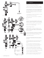
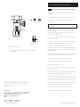
G U I DA N C E N OT E S
Solar Collectors
Installation, Commissioning & Controller
Wiring Guide for East/West Array
Please leave these instructions
with the User
© Baxi Heating UK Ltd 2011
Contents
These instructions should be read in conjunction with the 1st & 2nd fix Solar
Installation Guide.
East West Array is perfect for roof orientations which are not south facing. The kit
enables collectors to be fitted either side of the roof structure – one panel facing east
and one facing west.
This permits improved solar gain throughout the day. The solar controller supplied
with the system pump station provides the facility built in to control an East West
Array.
Kits Contain:
•
2m Flexible Pipe Kit
•
13m Solar Sensor Wire
•
Cascade Module
•
Solar Panel Sensor
•
2 x 22mm Compression Fittings
•
1 Collector and appropriate Mounting Kit
2
© Baxi Heating UK Ltd 2011
1.0
Introduction to Solar
3
2.0
Installation
4
3.0
Pump and Sensor Connections
6
4.0
Commissioning the System
7
1.0 Introduction to Solar
1
2
3
4
5
6
7
8
9
10
11
12
Cold Supply for Domestic Hot Water
Domestic Hot Water Outlet
Auxiliary Discharge Arrangement
Solar Collector 1 (West facing)
Solar Collector 2 (East facing)
Collector Sensor 1 (PT 1000)
Collector Sensor 2 (PT 1000)
Solar Pumping Station with Controller
Solar Pumping Station Cascade Module
Solar Expansion Vessel
Auxiliary Heat Source (Central Heating Boiler)
Flow Meter on a ‘COMMON’ Return (Kit)
Solar Fluid is not supplied with the East West array kit. Where
additional fluid is required, it must be compatible with the fluid
used in the existing system. The Solar fluid must not be mixed
with any other type of fluid or diluted. Failure to observe these
requirements will invalidate the product warranty.
Where possible all pipe runs between collectors should be as
short as possible.
For system controller wiring of the east west array, refer to
page 6.
7
5
6
4
2
8
Blending
Valve
10
3
9
East/West
array kit
11
12
12
1
Combi
Valve
System
FIg. 1 Schematic System Diagram
© Baxi Heating UK Ltd 2011
3
2.0 Installation
If fitting this as an extension to an existing solar system, drain the
solar fluid then flush and clean the existing system.
1. Mount the east-west array cascade module in a convenient
location close to the main system pump station and controller.
2. Connect the pipework as shown in Fig. 1 ensuring the outlets
from both collectors form a common flow through the system
pump station, and that the flow meter and return temperature
sensor (if these are fitted) are mounted on a common section
of the return pipe.
To a suitable
container
3. Fit a blanking cap to the outlet of the safety group on cascade
module below the PRV, as shown in Fig. 2.
Fig. 2
3
9
45°
4
4. Route a pipe from the outlet of the PRV to a suitable solar
fluid catchment vessel.
Air Test
5
1. An air test may be used on the pipework to detect any gross
leakage prior to flushing and filling with solar heat transfer fluid.
Pressurise the system to a maximum of 1 bar to check for leaks.
1
8
2. Ensure that the solar expansion vessel pre-charge pressure
has been set prior to flushing and filling.
6
Flushing and Filling the pipework
6
2
6
7
Fig. 3
Read at top
of float
1. Before the system is commissioned the pipework must be
flushed to remove any contaminants. This must be done using
the solar heat transfer fluid as it will be impossible to fully drain
all parts of the system.
2. Connect the flushing pipes to the fill valve on the safety group
(Fig. 3 Item 1) and to the drain valve on the flow meter (Fig. 3
Item 2) of the system pump station as shown in Fig. 4.
3. Open the fill & drain valves.
4. Turn the slot of the adjusting screws in both of the return
lines (Fig. 3 Items 3 & 8) so the slot is vertical to open the nonreturn valves.
Filling pump
Filter
5. Close the isolating valve on the cascade module (Fig. 3 Item
9) so that the dot on thermometer bezel is at 9 o’clock
position.
6. Turn the isolating valve in the flow line with integral
thermometer (Fig. 3 Item 4) in the direction indicated by the
arrow (to a 45° position) to open the non-return valve.
7. Ensure that the right hand isolating valve with integral
thermometer in the return (Fig. 3 Item 5) is open indicated by
the dot on the thermometer bezel being at the top (12 o’clock).
Fig. 4
Solar fluid
8. Turn the slot of the flow meter adjusting screw (Fig. 3 Item 6)
in the return vertically to open the flow limiter.
9. Flush the solar primary pump by pumping the fluid into the
system via the fill valve on the safety group (Fig. 3 Item 1).
4
© Baxi Heating UK Ltd 2011
2.0 Installation
10. Close right hand isolating valve Fig. 3, Item 5 (dot on
thermometer bezel at 9 o’clock position). Flush solar primary
pipework and collector via the fill and drain valve on the safety
group.
NOTE: If reusing flushed fluid ensure this is filtered before
re-introducing into the system. (see Fig.4). Use a suitable
container of a large enough volume to collect the fluid.
11. Open the isolating valve on the cascade module (Fig. 3 Item
9 - dot on thermometer bezel at 12 o’clock position) and then
close the isolating valve on the flow line (Fig. 3 Item 4 - dot on
thermometer bezel at 9 o’clock position). Flush solar primary
pipework again via the fill and drain valve on the safety group.
12. When satisfied that all pipework and component parts have
been thoroughly flushed, the system can be filled.
13. Pour an amount of the solar heat transfer fluid into the filling
pump.
14. Close the fill valve - safety group (Fig. 3 Item 1) and the
drain valve - flow meter (Fig. 3 Item 2) and pressurise the pump
slightly prior to filling the system. If an electric pump is being
used follow the instructions with the pump.
15. Slowly open the fill valve on the safety group (Fig 3, item 1)
and pump fluid into the system. Whilst pumping, open the flow
meter drain valve (Fig 3, item 2) slightly to allow the air to vent
out of the system.
NOTE: When the pump is down to approximately 1 litre
isolate the fill and drain valves. Vent the filling pump and refill
with solar heat transfer fluid. Re-pressurise the filling pump
and repeat steps 14 and 15 above until fluid is seen
discharging from the drain valve on the flow meter. (Fig 3,
item 2).
16. Close the drain valve.
17. Continue filling at the fill valve on the safety group (Fig 3,
item 1) until the system pressure reaches 2 bar.
18. At this point the circulation pumps, air separator and any
other air vents installed in the system should be vented. If the
system pressure drops, repressurise using the procedure above.
19. After venting the pumps and checking that the system
pressure is 2 bar, close the fill valve on the safety group (Fig. 3
Item 1), and check the system for leaks.
20.Turn the left hand isolating valve (Fig 3, item 4) back
clockwise until the doton the bezel is back at 12 o’clock.
21.Turn the right hand isolating valve (Fig. 3 Item 5) back 90°
clockwise until the dot on the bezel is back at 12 o’clock.
22. Turn the slot of the adjusting screws (Fig. 3 Items 3 & 8)
back to the horizontal position to close the non-return valve.
© Baxi Heating UK Ltd 2011
5
3.0 Pump & Sensor Connections
3.1
240 Volts
Pump & Sensor Connections To Solar
Controller
Fuse rating T 2A L 250V
Collector 1 (West facing) temperature sensor connected to
terminals marked T1 (polarity free)
FUSE
PE
PE
A2
A3
A1
L
T2
T1
T3
T4
T5
T6
T7
Collector 2 (East facing) temperature sensor connected to
terminals marked T3 (polarity free)
PE
PE
N
N
N
N
M1 M2 M3
Terminal
Reference
Description
L
240V Supply Live
N
240V Supply Neutral
A1
Switched Output to Solar Pump
N
Solar Pump Neutral
A2
Switched Output - Live 2
N
Switched Output 2 Neutral
A3
Switched Output - Live 3
N
Switched Output 3 Neutral
PE
M5 M6 M7
Low Voltage (SELV) connections
Mains 230/240V connections
Fig. 5
M4
Earth Connection
T1 & M1
Temperature Sensor Collector 1
T2 & M2
Temperature Sensor Storage Tank 1
T3 & M3
Temperature Sensor Collector 2/Storage Tank 2
T4 & M4
Temperature Sensor Collector Return
T5 & M5
Temperature Sensor for 2nd temperature differential controller
T6 & M6
Frost Protection or 2nd temperature differential controller
T7 & M7
Flow Meter (Optional)
Cylinder temperature sensor connected to terminals marked
T2 (polarity free)
System Pump circuit to Collector 1 connected to terminals
marked A1 and N (240V terminals – observe polarity)
Cascade Pump circuit to Collector 2 connected to terminals
marked A2 and N (240V terminals – observe polarity)
NOTE: Refer to the instruction manual supplied with the
solar controller if the wiring layout differs from the one
shown in Fig. 5.
The collector temperature sensors must be installed in the
relevant sensor pockets mounted on the collector and sealed
using high temperature UV resistant silicone sealant.
Refer to the relevant Collector Mounting Installation Guide for
details of the position of the sensor pockets. Only the BLACK
sleeved sensors should be used in the collector.
4.2
Setting The Solar Controller System Parameter
To East West Configuration
• Turn the power off to the solar controller (System Pump
Station).
• Turn the power back on to the solar controller (settings can
only be adjusted in the first minute of powering up.
• Press the right button until the spanner symbol is displayed
(
).
• Reset the system parameter for the hydraulic system layout
to show ‘4’ (refer to the instruction manual provided with the
solar controller).
• Press the right button so that the OK symbol appears.
• Press the right button again to set and confirm new
parameter 4 (East/West Array).
6
© Baxi Heating UK Ltd 2011
4.0 Commissioning the System
For step by step guide to operate the controller, refer to
commissioning instructions.
Ensure collectors temperatures are cool before this process.
1
4.1
1. Turn the power to the solar controller. This should display
the information screen.
2
3
5
4
Ensure the Solar Primary System is free from air
2. Key the left button (Fig. 6, item 3) once to enter the main
menu screen. The ‘i’ icon will flash (See section 11 of the 2nd
fix Solar manual for a description of the solar controller button
functions).
Fig. 6
WARNING: During this commissioning stage the safety
temperature control is disabled. Ensure collectors are cool.
3. Each pump unit needs to be set up individually.
4. Press the right button (Fig. 6 item 5) twice to select the
manual operation menu (
). Press the down button and
the ‘pump’ symbol and the ‘switch output 1 and 2 symbols
should now be seen with a ‘zero’ displayed. Changing the ‘zero’
to a ‘one’ will operate the pump. To do this, press the right
button and the ‘zero’ will flash.
5. Press either the up or down button to manually activate
pump 1, then key right to accept the setting. See
commissioning section to follow controller settings.
6. Leave the pump running for sufficient time to allow any
residual air to be purged from the system via the air separator
and any bleed points fitted to the system. Use the flow gauge
window (Fig. 3, item 7) as a visible indicator of the air bubbles.
NOTE: During this time the joints may be checked for leaks.
7. Stop the pump using the button procedure described
previously (paragraph 4). If pressure has been lost from the
system during the air bleeding process, the top up procedure
described earlier can be repeated to top up the system.
8. Repeat 5 to 7 for pump 2, and select pump 2.
4.2
Setting the System Pressure
a) During commissioning, the system pressure should be 0.7
bar above the static pressure (1 metre height differential equals
0.1 bar). However, it must be at least 1.5 bar and no higher
than 2.2 bar.
b) Determine the system pressure when the system is cold
(20°C). This should be recorded on the Commissioning
Record Sheet in the second fix manual.
c) If the pressure is too low you should pump additional heat
transfer fluid into the system; the fill valve on the safety group
(Fig. 3 Item 1) needs to be opened for this purpose. When
system pressure is correctly set, ensure the fill valve is closed
and remove filling hose from safety group.
d) Remove all tubing from the fill valve on the safety group (Fig
3, item 1) and the drain valve on the flow meter. (Fig 2, item 2)
and replace both the sealing caps securely, ensuring that the
rubber seals are fitted. Check for leaks.
© Baxi Heating UK Ltd 2011
7
4.0 Commissioning the System
4.3
Checking and adjusting the flow rate East/West
1. Adjust the flow rate when the system is cold (20°C)
(see Fig. 7).
2. The flow rate should be adjusted to give the optimum flow.
1
Open
Closed
3. Manually operate the cascade pump (see section 4.1
paragraph 4).
Warning: The temperature control is disabled during this
procedure.
2
4. Set the cascade pump speed selector so that the required
flow rate is achieved or exceeded with the lowest possible
setting. The flow gauge adjusting screw (Fig. 7, item 1) can be
used to fine-tune the flow rate.
5. Set the required flow rate for the collector array connected
to the cascade module.
Fig. 7
Read at top
a) The float in the flow gauge will indicate the circulation flow
rate through the flow gauge sight glass (Fig. 7, Item 2).
of float
Key - Item Identification
1
2
Flow Gauge Adjustment Screw (shown in open position)
Flow Gauge
b) Adjust screw of the flow limiter (Fig. 7, item 1) with a
screwdriver, until the upper edge of the float in the sight glass
indicates the required flow rate. Turn the screw anticlockwise
to increase the flow.
c) Ensure that the float is stable when the pump is running. No
air bubbles should be observed during this procedure.
d) Set manual pump operation to off (reset to zero).
e) Refit the front facia moulding onto the rear moulding.
6. Manually operate System Pump 1.
7. Set the required flow rate for the collector array connected
to the cascade module.
a) The float in the flow gauge will indicate the circulation flow
rate through the flow gauge sight glass (Fig. 7 Item 1).
b) Adjust screw of the flow limiter with a screwdriver, until the
upper edge of the float in the sight glass indicates the required
flow rate. Turn the screw anticlockwise to increase the flow.
All descriptions and illustrations provided in this leaflet have been carefully
prepared but we reserve the right to make changes and improvements in
our products which may affect the accuracy of the information contained in
this leaflet. All goods are sold subject to our standard Conditions of Sale
which are available on request.
c) Ensure that the float is stable when the pump is running. No
air bubbles should be observed during this procedure.
d) Set manual pump operation to off (reset to zero).
M U L T I F IT
e) Refit the front facia moulding onto the rear moulding.
A Tr a din g D i v i s i o n o f B ax i H eat i ng U K Lt d ( 3879156)
Brooks House, Coventry Road, Warwick. CV34 4LL
Technical Enquiries 0844 871 1568
Website www.bdrthermea.com
e&oe
© Baxi Heating UK Ltd 2011
UK Comp No 720862801 (4/11)