1
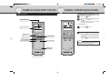
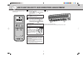
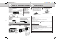
ADVANCED AND EVER ADVANCING
REMOTE CONTROLLER
OPERATING INSTRUCTIONS
MAC-101HRC-E
CONTENTS
SAFETY PRECAUTIONS .................................................................................... 2
• This remote controller is for the exclusive use of the following models:
MSH09NW, MSH12NN, MSH15NN, MSH17NN
MSH09NW2, MSH12NN2, MSH15NN2, MSH17NN2
MSH09TW, MSH12TN, MSH15TN, MSH17TN
• To use this remote controller correctly and safely, be sure to read this operating instructions before use. Keep
this manual carefully for later reference.
NAME OF EACH PART FOR R/C ........................................................................ 3
MANUAL OPERATION (COOL/HEAT) ................................................................. 3
AIR FLOW VELOCITY AND DIRECTION ADJUSTMENT .................................. 4
NAME OF EACH PART FOR UNIT ...................................................................... 5
FOR OWNERS .................................................................................................... 5
SAFETY PRECAUTIONS
•
Since the cautionary items shown here are important for safety, be sure to observe them.
Marks and their meanings are as shown below.
CAUTION
Incorrect handling could cause a serious hazard depending on the conditions.
Meanings of symbols used in this manual are as shown below.
Be sure not to do.
Be sure to follow the instruction.
CAUTION
Replace the 2 batteries
with new ones of same
type.
•
Using an old battery together
with a new one may result in
heat generation, leakage or an
explosion.
Do not charge or disassemble the batteries
and do not throw them
into a fire.
•
This may result in leakage, fire
or an explosion.
If liquid from the alkaline batteries gets onto
your skin or clothes,
wash it well with clean
water.
•
If liquid from the alkaline batteries gets into your eyes,
wash them well with clean water and consult a doctor at
once.
Handling of the remote controller
•
•
•
The range that the signal can reach is about 20 feet when the remote controller is pointed at the front of
the indoor unit.
When a button is pressed, one or two beeps will be heard from the indoor unit. If no sound is heard,
operate again.
Use the remote controller carefully.
If it is dropped, thrown or it gets wet, the remote controller may not operate.
2
NAME OF EACH PART FOR R/C
MANUAL OPERATION(COOL/HEAT)
To select the COOL or HEAT mode
Remote controller
ON/OFF
1
2
Signal transmitting section
Press the
button.
Select the operation mode by pressing
COOL/HEAT button.
the
Each time this button is pressed, the operation
mode alternates COOL and HEAT.
COOL
COOL
Operation display section
HEAT
AUTO
F
HEAT
AUTO
ON/OFF (operate/
stop) button
AUTO
AUTO
ON/OFF
ON/OFF
F
TEMPERATURE
DOWN
UP
TEMPERATURE
DOWN
UP
Temperature buttons
To stop operation:
■
■
ON/OFF
Press the
button.
When the set temperature is to be changed:
DOWN
■ Press the
button to lower the temperature. One press lowers the temperature by
about 2 °F.
UP
COOL/HEAT
Operation select button
COOL/HEAT
FAN
FAN
VANE
VANE
Fan speed control button
Vane control button
■ Press the
button to raise the temperature.
One press raises the temperature by about
2 °F.
NOTE
When the ambient temperature is too high, the room
temperature may not reach the set temperature since
the unit operates to cool under high load.
RESET
RESET button
RESET
(This diagram shows an overall view.)
3
AIR FLOW VELOCITY AND DIRECTION ADJUSTMENT
AIR FLOW velocity and direction can be selected as required.
■
•
•
COOL
HEAT
AUTO
ON/OFF
F
AUTO
TEMPERATURE
DOWN
UP
COOL/HEAT
FAN
VANE
Each time the button is pressed, the fan speed is
(Med.) →
changed in sequence: (Low) →
(High) → AUTO
To change the horizontal direction of the air flow, move the vertical vane manually.
Use the
(High) notch to cool/heat the room more.
If the operating sound of the air conditioner disturbs
your sleep, use the (Low) notch.
■
To change the AIR FLOW blowing direction vertically, press the VANE button.
Each time the button is pressed, the angle of the
horizontal vane is changed in sequence: (1) →
(2) → (3) → (4) → (5) → (SWING) →AUTO
SWING OPERATION
Adjust the vane before operation starts.
Since the horizontal vane moves automatically, your fingers may be caught.
Use the swing operation for the air flow to reach all corners of the room.
Recommended horizontal
vane range
Use the AUTO position usually.
Use position (1) or (2) in the
COOL mode and use positions
(3) to (5) in the HEAT mode
when adjusting to your requirements.
RESET
■
To change the AIR FLOW velocity,
press the FAN button.
COOL
1
2
3
HEAT
4
5
NOTE
■ In the cooling operation, when the air conditioner is
operated with setting the horizontal vane to (4) or
(5) for 1 hour, the AIR FLOW direction is automatically set to horizontal to prevent condensed water
from dropping.
■ Adjust the vertical AIR FLOW direction using the remote controller. If the horizontal vane is moved manually, it may cause trouble.
■ In the heating operation, if the air flow temperature
is too low or when defrosting is being done, the horizontal vane position is set to (1).
4
NAME OF EACH PART FOR UNIT
FOR OWNERS
Indoor unit
Remote controller (How to set the batteries)
MSH09NW, MSH09NW2, MSH09TW
Front panel
Air cleaning filter
(White bellows
type) (OPTION)
Air inlet
MSH12NN, MSH15NN,
MSH17NN
MSH12NN2, MSH15NN2,
MSH17NN2
MSH12TN, MSH15TN,
MSH17TN
1
Remove the back lid and insert
batteries. Then reattach the back
lid.
Press the RESET button.
Press using
a thin stick.
Insert the minus pole of the batteries first.
Check if the polarity of the batteries is correct.
Deodorizing filter
(Gray sponge
type) (OPTION)
■ If the RESET button is not pressed, the remote controller may not operate correctly.
Remote control
receiving section
Air filter
2
Insert the minus pole
of the batteries first.
Vertical vane
Horizontal vane
Handling of the remote controller
•
•
•
Display section
MSH09NW
MSH09NW2
MSH09TW
MSH12NN, MSH15NN, MSH17NN
MSH12NN2, MSH15NN2, MSH17NN2
MSH12TN, MSH15TN, MSH17TN
Operation Indicator
Operation
Indicator lamp
Receiving section
The range that the signal can reach is about 20 feet when the remote controller is pointed at the front of
the indoor unit.
When a button is pressed, one or two beeps will be heard from the indoor unit. If no sound is heard,
operate again.
Use the remote controller carefully.
If it is dropped, thrown or it gets wet, the remote controller may not operate.
When installing on a wall, etc.
Operation
Indicator lamp
•
Receiving
section
Install the remote controller installation case in a position where the signal reception sound (beep) can
be heard from the indoor unit when the ON/OFF button is pressed.
Dry-cell batteries
Reference for replacing batteries
Outdoor unit
MUH09NW
MUH09NW2
MUH09TW
MUH12TN
When the indoor unit does not respond to the signal from the remote controller, or the display becomes
dim, replace the batteries with new ones (size AAA).
Though both alkaline batteries and manganese batteries can be used, alkaline batteries are recommended because their service life is longer than that of manganese batteries.
The service life of an alkaline battery is about 1 year.
However, a battery which the time limit is approaching may be exhausted soon. The recommended
usable time limit is indicated (month/year) on the bottom of the battery.
Replace the 2 batteries with new ones of the same type.
Do not use rechargeable batteries.
To prevent liquid leakage, take out all batteries when the remote controller is not going to be used for a
long time.
Dispose of exhausted batteries in the correct manner.
MUH12NN, MUH15NN
MUH12NN2, MUH15NN2
MUH15TN
•
•
Air inlet
•
•
•
•
(back and side)
Piping
Drainage hose
Air outlet
MUH17NN, MUH17NN2
MUH17TN
Refer to OPERATING INSTRUCTIONS attached to the air conditioner for details.
Drain outlet
5
3400 Lawrenceville Suwanee Road ● Suwanee, Georgia 30024
Toll Free: 800-433-4822 ● Toll Free Fax: 800-889-9904
www.mrslim.com
Specifications are subject to change without notice.