1
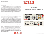
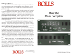
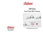
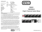
LIMITED WARRANTY
This product is warranted to the original consumer purchaser to be free
from defects in materials and workmanship under normal installation, use and
service for a period of one (1) year from the date of purchase as shown on the
purchaser’s receipt.
The obligation of Rolls Corporation under this warranty shall be limited
to repair or replacement (at our option), during the warranty period of any part
which proves defective in material or workmanship under normal installation,
use and service, provided the product is returned to Rolls Corporation, TRANSPORTATION CHARGES PREPAID. Products returned to us or to an authorized
Service Center must be accompanied by a copy of the purchase receipt. In the
absence of such purchase receipt, the warranty period shall be one (1) year from
the date of manufacture.
This warranty shall be invalid if the product is damaged as a result of
defacement, misuse, abuse, neglect, accident, destruction or alteration of the
serial number, improper electrical voltages or currents, repair, alteration or
maintenance by any person or party other than our own service facility or an
authorized Service Center, or any use violative of instructions furnished by us.
This one-year warranty is in lieu of all expressed warranties, obligations
or liabilities. ANY IMPLIED WARRANTIES, OBLIGATIONS, OR LIABILITIES, INCLUDING BUT NOT LIMITED TO THE IMPLIED WARRANTIES
OF MERCHANTABILITY AND FITNESS FOR A PARTICULAR PURPOSE,
SHALL BE LIMITED IN DURATION TO THE ONE YEAR DURATION OF
THIS WRITTEN LIMITED WARRANTY. Some states do not allow limitations
on how long an implied warranty lasts, so the above limitation may not apply to
you.
IN NO EVENT SHALL WE BE LIABLE FOR ANY SPECIAL, INCIDENTAL OR CONSEQUENTIAL DAMAGES FOR BREACH OF THIS OR
ANY OTHER WARRANTY, EXPRESSED OR IMPLIED, WHATSOEVER.
Some states do not allow the exclusion or limitation of special, incidental or
consequential damages so the above limitation or exclusion may not apply to
you. This warranty gives you specific legal rights, and you may also have other
rights which vary from state to state.
ROLLS CORPORATION
SALT LAKE CITY, UTAH
7/02
RM64
FOUR ZONE MIXER
ZONE
SELECT
ZONE
SELECT
1 2 3 4 5 6 7 8
1 2 3 4 5 6 7 8
LEVEL
12341234
ZONE
SELECT
LEVEL
LEVEL
12341234
1 2 3 4 5 6 7 8
LEVEL
LEVEL
12341234
FOUR
ZONE
MIXER
LEVEL
LEVEL
LEVEL
LEVEL
LEVEL
pwr
RM64
OWNERS MANUAL
INTRODUCTION
SPECIFICATIONS
Thank your for your purchase of the Rolls RM64 Four Zone Mixer. The RM64
combines two paging microphones with up to four line level source inputs. Each
input is switch selected to output to any combination of four zone outputs. The
outputs are all balanced XLR connectors, and a 1/4" Remote Volume jack provides each zone with the means for external volume control. The Microphone
inputs feature automatic ducking for easy paging.
The RM64 is the ideal solution for banquet rooms, offices, restaurant/night clubs,
etc.
NOTE: This unit is intended for professional installation. Certain assumptions have
been made that the installer has the required knowledge to properly install and
setup and operate the RM64.
FEATURES:
• Two Microphone and Four RCA Source Inputs
• Four XLR Balanced Zone Outputs
• 12 VDC Phantom Power available for each Mic Input
• Remote Volume control jacks fro each Zone Output
• Switchable Ducking for the Mic Inputs
INSPECTION
1. Unpack and inspect the RM64 box and package.
If obvious physical damage is noticed, contact the carrier immediately to make a
damage claim. We suggest saving the shipping carton and packing materials for
safely transporting the unit in the future.
2. Please visit our website at www.rolls.com for Warranty Registration, or complete the Warranty Registration Card and return it to the factory.
TABLE OF CONTENTS
INTRODUCTION
..............................................................
FEATURES
..............................................................
INSPECTION
..............................................................
TABLE OF CONTENTS ..............................................................
DESCRIPTION
..............................................................
CONNECTION
..............................................................
OPERATION
..............................................................
SCHEMATIC
..............................................................
SPECIFICATIONS
..............................................................
WARRANTY
..............................................................
1
Input Impedance:
Output Impedance:
Max Input Level:
Phantom Power:
Input Connectors:
Outputs:
Max Gain:
S/N Ratio:
THD
IMD (SMPTE)
CMRR
Frequency Response:
Power
Weight:
Size:
10K 9balanced
50K 9 unbalanced RCA
50 9 Balanced XLR
Mic:
+10 dB
Source:
+22 dB
+12 Volts DC, 5mA max.
XLR and RCA
4 ea. XLR
60 dB mic
30 dB line
>75 dB
< .3%
< .3%
90 dB
20Hz to 20kHz +/- 0 dB
120 VAC 50-60 Hz, 15 W
7 lbs (3KG)
19" x 1.75" x 6.5"
(48cm x 4.5cm x 17cm)
1
1
1
1
2
3
4
5
6
BACK COVER
6
SCHEMATIC
DESCRIPTION
FRONT PANEL
LEVEL
ZONE
SELECT
ZONE
SELECT
ZONE
SELECT
1 2 3 4 5 6 7 8
1 2 3 4 5 6 7 8
1 2 3 4 5 6 7 8
LEVEL
12341234
LEVEL
12341234
LEVEL
LEVEL
FOUR
ZONE
MIXER
LEVEL
12341234
LEVEL
LEVEL
LEVEL
LEVEL
pwr
RM64
MIC INPUTS 1, 2: These LEVEL controls adjust the volume of the indicated
Microphone channel.
SOURCE INPUTS 1 - 4: These LEVEL controls adjust the volume of the indicated
Source channel.
ZONE SELECT: DIP switches for assigning the indicated Mic or Source channel
to the Zone Outputs. The four switches closest to the channel LEVEL control
assign that channel to the zones.
ZONE OUTPUTS: These LEVEL controls adjust the output volume of the indicated ZONE.
pwr LED: When lit, indicates the RM64 is on.
Power switch: Turns the RM64 on and off.
REAR PANEL
MODEL RM64
MADE IN USA
OUTPUT
3
OUTPUT
4
SERIAL NUMBER
OUTPUT
2
OUTPUT
1
4
3
2
INPUT
2
1
INPUT
1
64-
REMOTE
VOLUME
WARNING:
120 VAC
TO RAIN OR MOISTURE
NO USER SERVICABLE PARTS INSIDE.
50/60Hz 15VA
RISQUE DE CHOC - NE PAS ENLEVER
REMOTE
VOLUME
REMOTE
VOLUME
ZONE PHANTOM
DUCK POWER
ASSIGN
4 3 2 1 2 1
REMOTE
VOLUME
DO NOT EXPOSE THIS EQUIPMENT
1 2 3 4 5 6
ZONE FOUR
ZONE THREE
ZONE TWO
ZONE ONE
SOURCE INPUTS
TRIM
TRIM
MIC TWO
MIC ONE
C
US
ZONE OUTPUTS 1 - 4: Line level (+4 dB ref.) balanced male XLR jacks for
connection to the zone amplifiers.
REMOTE VOLUME: These four 1/4” TRS jacks connect to a remote volume
potentiometer.
SOURCE INPUTS 1 - 4: RCA input jacks for connection to CD Players, Tuners
etc.
ZONE DUCK ASSIGN/PHANTOM POWER SWITCHES: This set of DIP switches,
from left to right;the first four assign which zone will have the source signal(s)
ducked by the Microphone Inputs, the last two apply phantom power to the
indicated microphone channel.
MIC INPUT 1 - 2: Balanced female XLR jacks for connection to dynamic or
condenser type microphones.
TRIM 1 - 2: Adjusts the input sensitivity for the indicated Mic Input.
5
2
CONNECTION
OPERATION
ZONE
SELECT
ZONE
SELECT
1 2 3 4 5 6 7 8
1 2 3 4 5 6 7 8
LEVEL
Referring to the diagram above, connect microphones to the MIC
INPUTs and apply phantom power where needed. Connect sources
such as cassette players, CD players, AM/FM tuners, etc. to the
RCA Source Inputs. Note which input each device is connected to
as that input corresponds to its front panel Level control. Connect
the XLR outputs to their respective zone amplifiers and speakers.
The balanced signals are configured to pin 2 hot, pin 3 neutral, and
pin 1 ground. For ground lifting it will be necessary to remove the
connection to pin 1.
For Remote Volume operation, a Tip-Ring-Sleeve plug will need to
be wired to a 10 - 100 K Ohm potentiometer as shown in the diagram below.
12341234
LEVEL
LEVEL
12341234
LEVEL
SETTING THE DIP SWITCHES
Each input is assigned to a Zone via the four DIP switches nearest
that Input Level control. The zone is assigned when the switch is in
the DOWN position. For example, the switch settings above send
Mic 1 to all four Zones; 1, 2, 3, and 4. Mic 2 is sent to Zone 1 only.
Source 1 is sent to Zone 1 and Source 2 is sent to Zones 2, 3, and
4.
The first four rear panel DIP switches assign which zone has priority paging, or ducking, when a signal is present at the microphones.
Switches 5 and 6 assign phantom power to the indicated microphone. Shown below; Zones 1, 2, and 3 have paging assigned, and
Microphone 1 has the phantom power engaged.
INPUT
2
1
INPUT
1
ZONE PHANTOM
DUCK POWER
ASSIGN
4 3 2 1 2 1
1 2 3 4 5 6
TRIM
TRIM
MIC TWO
MIC ONE
C
US
10K to 100K Ohm
Linear taper potentiometer
Sleeve
Tip
Ring
3
4