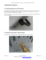
1
Product Manual and User Guide
for
62 100 – ThurayaIP Active Portable Antenna
Product Manual and User Guide – ThurayaIP Active Antenna
The information in this document is subject to change without notice and describes
only the product defined in the Introduction of this documentation. This document is
intended for the use by SCAN Antenna customers only for the purposes of the
agreement under which the document is submitted, and no part of it may be
reproduced or transmitted in any form or means without the prior written permission
of SCAN Antenna. The document has been prepared to be used by professional and
properly trained personnel, and the customer assumes full responsibility when using
it. SCAN Antenna welcomes customer comments as part of the process of continuous
development and improvement of the documentation.
The information or statements given in this document concerning the suitability,
capacity, or performance of the mentioned hardware products cannot be considered
binding but shall be defined in the agreement made between SCAN Antenna and the
customer. However, SCAN Antenna has made all reasonable efforts to ensure that the
instructions contained in the document are adequate and free of material errors and
omissions. SCAN Antenna will, if necessary, explain issues which may not be covered
by the document.
SCAN Antenna liability for any errors in the document is limited to the documentary
correction of errors. SCAN Antenna WILL NOT BE RESPONSIBLE IN ANY EVENT FOR
ERRORS IN THIS DOCUMENT OR FOR ANY DAMAGES, INCIDENTAL OR
CONSEQUENTIAL (INCLUDING MONETARY LOSSES), that might arise from the use of
this document or the information in it.
This document and the product it describes are considered protected by copyright
according to the applicable laws.
SCAN Antenna logo is a registered trademark of SCAN Antenna A/S.
Other product names mentioned in this document may be trademarks of their
respective companies, and they are mentioned for identification purposes only.
Copyright © SCAN Antenna A/S 2010. All rights reserved.
Version A
30. august 2010
SCAN Antenna A/S – www.scan-antenna.com
Page 2 of 18
Product Manual and User Guide – ThurayaIP Active Antenna
Table of contents
1.
2.
3.
4.
5.
Introduction .............................................................................................................. 5
Functional description ................................................................................................ 5
Box contents ............................................................................................................. 6
Safety ...................................................................................................................... 6
Mechanical features ................................................................................................... 7
5.1 Antenna placement on flat surface .......................................................................... 7
5.2 Antenna mounting on camera tripod ....................................................................... 7
5.3 Antenna mounting on 1” bracket ............................................................................ 8
5.4 Storing and carrying the antenna ........................................................................... 9
6. Interface ................................................................................................................ 10
6.1 ON/OFF switch ................................................................................................... 10
6.2 Power LED / Charging indicator ............................................................................ 11
6.3 Charger socket ................................................................................................... 11
6.4 SAT connector.................................................................................................... 12
6.5 GPS connector.................................................................................................... 13
7. Power options ......................................................................................................... 14
7.1 Using battery ..................................................................................................... 14
7.2 Using charger..................................................................................................... 14
7.3 Using DC-feeder ................................................................................................. 14
8. Use of the antenna .................................................................................................. 15
9. Troubleshooting....................................................................................................... 16
10. Cable guidelines..................................................................................................... 17
11. Specifications ........................................................................................................ 18
Version A
30. august 2010
SCAN Antenna A/S – www.scan-antenna.com
Page 3 of 18
Product Manual and User Guide – ThurayaIP Active Antenna
THIS PAGE INTENTIONALLY LEFT BLANK
Version A
30. august 2010
SCAN Antenna A/S – www.scan-antenna.com
Page 4 of 18
Product Manual and User Guide – ThurayaIP Active Antenna
1. Introduction
Thank you for choosing a product from SCAN Antenna. This product has been carefully
developed with your satisfaction in mind. SCAN Antenna believes in long relationships with its
customers, and we hope that you will find the quality of this product satisfactory.
Contact info for SCAN Antenna:
SCAN Antenna A/S
Dyregårdsvej 1-3
DK-2740 Skovlunde
DENMARK
Phone
Fax
Email
WWW
(45) 43 33 16 20
(45) 44 94 10 99
[email protected]
www.scan-antenna.com
If your antenna has been purchased through a distributor, please contact your distributor for
support.
2. Functional description
This product,
ThurayaIP Active Portable Antenna (P/N 62 100)
is designed exclusively for use with a ThurayaIP terminal (model no. 9103, by Hughes Network
Systems). The use of this antenna with any other products is not supported.
This antenna enables the use of the highest streaming IP rates of ThurayaIP, and improves
performance for all other modes.
This antenna also enables the use of long cables between the ThurayaIP terminal and the
antenna.
The antenna consists of a directional antenna, a High-Power Amplifier (HPA) for the uplink, a
Low-Noise Amplifier (LNA) for the downlink, and the necessary power supply circuitry. This
enables the antenna to meet the required satellite link specifications for the ThurayaIP system.
The antenna must have power available (see chapter 7), and the antenna must be pointed
towards the satellite for proper operation.
Version A
30. august 2010
SCAN Antenna A/S – www.scan-antenna.com
Page 5 of 18
Product Manual and User Guide – ThurayaIP Active Antenna
3. Box contents
The antenna is delivered in a box containing all necessary accessories, except long coaxial
cables, which are packaged separately.
-
ThurayaIP Active Portable Antenna (battery included)
AC charger
AC power cord
1” Flange for optional mounting on bracket
User guide (this document)
DC – feeder (optional)
4. Safety
The antenna radiates electromagnetic waves when transmitting. In order to comply with
current FCC RF Exposure limits, the antenna must be installed in a way such that no persons
can placed directly in front of the antenna within the minimum safe distance. The minimum
safe distance for this antenna is 60 cm (2 ft).
WARNING! Maintain a distance of 60 cm (2 ft)
from the front of the antenna.
Version A
30. august 2010
SCAN Antenna A/S – www.scan-antenna.com
Page 6 of 18
Product Manual and User Guide – ThurayaIP Active Antenna
5. Mechanical features
5.1 Antenna placement on flat surface
The antenna can be placed on any flat surface. Adjustable handle allows the antenna to be
fixed at the correct elevation angle. Consult the Thuraya IP user interface for the correct
elevation and azimuth angles of your position.
Loosen the finger-screws (counter-clockwise), adjust the elevation angles, and tighten them
again (clockwise).
5.2 Antenna mounting on camera tripod
The antenna has a threaded mount compatible with many camera tripods.
Version A
30. august 2010
SCAN Antenna A/S – www.scan-antenna.com
Page 7 of 18
Product Manual and User Guide – ThurayaIP Active Antenna
5.3 Antenna mounting on 1” bracket
The antenna comes with an extra adaptor for a 1” thread mount. The adaptor is mounted on
the rear of the antenna, if needed.
The thread is of the type
Version A
1”-14 NF.
30. august 2010
SCAN Antenna A/S – www.scan-antenna.com
Page 8 of 18
Product Manual and User Guide – ThurayaIP Active Antenna
5.4 Storing and carrying the antenna
When storing the antenna, place the handle in the ‘down’ position, where the handle covers
connectors and take up minimum amount of space.
When carrying the antenna, place the handle in the ‘up’ position.
Version A
30. august 2010
SCAN Antenna A/S – www.scan-antenna.com
Page 9 of 18
Product Manual and User Guide – ThurayaIP Active Antenna
6. Interface
The antenna has the following interfaces:
6.1 ON/OFF switch
The ON/OFF switch is used to turn the antenna on and off.
However, it is only in use if the power source of the antenna is the battery, please see chapter
5 for power options. If the power comes from the charger or the DC-feeder, the antenna will
be on regardless of the position of the ON/OFF switch.
The primary purpose of the ON/OFF switch is to avoid battery discharge, if the antenna is not
being used.
Power Source
Battery only
Battery with charger
Charger only
DC feeder
DC feeder
Charger
Version A
and
or
Switch in ON position
Antenna is ON
Antenna is ON, battery is
being charged
Antenna is ON, battery is not
being charged
Switch in OFF position
Antenna is OFF
Antenna is ON, battery is
being charged
Antenna is ON, battery is
not being charged
Not recommended
Not recommended
30. august 2010
SCAN Antenna A/S – www.scan-antenna.com
Page 10 of 18
Product Manual and User Guide – ThurayaIP Active Antenna
6.2 Power LED / Charging indicator
The Power LED indicates that the antenna has power (is turned on). The LED indicates these
possible conditions:
OFF
The antenna receives no DC power, neither from battery, charger or
DC-feeder.
Flashing Green
The battery is being charged. The antenna can be used while
charging. When the battery is fully charged, the flashing will be
replaced by a constant ON.
ON
The antenna is turned on and is receiving DC power from the battery
or the charger (and the battery is fully charged) or the DC-feeder.
6.3 Charger socket
Connect the charger here. The charger that comes with the antenna must be used. However, if
it becomes necessary to use a replacement charger, the charger must meet the following
specifications:
Output voltage:
Output current min. rating:
Connector:
Version A
18 – 24 V DC
3 Amps
2.5 mm male plug
30. august 2010
SCAN Antenna A/S – www.scan-antenna.com
Page 11 of 18
Product Manual and User Guide – ThurayaIP Active Antenna
6.4 SAT connector
This is a snap-on connector of type “QMA”. It is the main interface between the ThurayaIP
terminal and the antenna. This connector must always be connected, or no satellite connection
will be possible.
This connector connects to the “Passive antenna” port of the ThurayaIP, even though it is an
active antenna. Do not connect this port to the “Active antenna” port.
The passive antenna port has an SMB connector on the ThurayaIP, so the coaxial cable
connection, including any jumpers, must have a male QMA connector on one end, and a
female SMB connector on the other end.
Version A
30. august 2010
SCAN Antenna A/S – www.scan-antenna.com
Page 12 of 18
Product Manual and User Guide – ThurayaIP Active Antenna
6.5 GPS connector
This is a snap-on connector of type “QMA”. It connects an active GPS antenna (internal to the
ThurayaIP Antenna) to the ThurayaIP terminal. The GPS antenna has a completely separate
power circuit, and the 3.3V necessary for the GPS antenna operation is provided by the
ThurayaIP terminal.
The connection of the GPS antenna is optional. The ThurayaIP terminal needs a GPS position,
but if one is not available, the last position from memory will be used, if it is not too old
(please consult the ThurayaIP manual for more information on this point).
If it is not convenient to use the built-in GPS antenna, a separate GPS antenna can be used
with the ThurayaIP terminal instead.
Version A
30. august 2010
SCAN Antenna A/S – www.scan-antenna.com
Page 13 of 18
Product Manual and User Guide – ThurayaIP Active Antenna
7. Power options
It is possible to power the antenna is several different ways:
7.1 Using battery
The antenna has a built-in Li-Ion battery. Only batteries approved by SCAN Antenna A/S may
be used, in order to avoid damage to the antenna or the battery. Do not attempt to replace
this battery with a different type.
The battery must be charged before use, using the correct charger. A fully discharged battery
will charge to full capacity in approximately 1.5 hour.
When fully charged, the antenna can operate at maximum streaming rate for more than 1
hour. The following discharge times are approximate:
Standard IP mode
Streaming IP 384 kbps
> 3 hours
> 1 hour
There is no indication of discharge except the LED, so when the battery is discharged, the
antenna will stop working.
7.2 Using charger
The charger can be used as a permanent source of power for the antenna. When the charger is
plugged in, the antenna will operate continuously. Should AC power have a disruption, the
battery (if mounted) will serve as a backup supply as indicated in the previous chapter.
The charger can also be used as permanent source of power when the battery is not
connected.
7.3 Using DC-feeder
The use of a DC-feeder is intended primarily for fixed installations of the antenna. For a fixed
installation using DC-feeder, the battery should be removed.
DC power must be connected to the DC-feeder. The antenna will be supplied by DC-power
through the coaxial cable.
The DC-feeder power option is also useful when the antenna needs to be separated from the
ThurayaIP terminal by a large distance. In this case the DC power supply can be adjacent to
the ThurayaIP terminal, and the antenna will not need a separate DC connection.
The charger can be used to feed power to the DC-feeder.
In case a separate power supply or battery is used, the voltage should be 12V minimum and
24V maximum. The power supply should be capable of delivering 33W minimum.
Version A
30. august 2010
SCAN Antenna A/S – www.scan-antenna.com
Page 14 of 18
Product Manual and User Guide – ThurayaIP Active Antenna
8. Use of the antenna
To start using your antenna with ThurayaIP, please follow this simple step-by-step procedure:
1) If the satellite position on the sky is unknown, first use the ThurayaIP without external
antenna, to determine the approximate elevation and azimuth angles.
2) Point the external antenna in the same direction.
3) Connect the coaxial cables between the ThurayaIP and the antenna. The GPS cable is
optional. If you are outdoors, the GPS cable is not necessary. The internal GPS antenna
of the ThurayaIP will suffice. When connecting the SAT cable, please be aware that
once the cable is connected in both ends, the ThurayaIP will immediately reboot. This is
normal behaviour.
4) Ensure the antenna has power available, either from battery, charger or DC-feeder.
5) Now the ThurayaIP will indicate that a ‘Passive External Antenna’ is present. This is
normal behaviour.
6) Use the signal-strength indicator of the ThurayaIP to adjust the final position of the
antenna. The signal strength indicator should be displaying signal strength immediately
when the antenna is connected, even when the connection is still “acquiring”.
7) Now all modes of the ThurayaIP will be available, including 384 kbps streaming in both
links.
8) For further use, please consult the ThurayaIP User Guide.
Version A
30. august 2010
SCAN Antenna A/S – www.scan-antenna.com
Page 15 of 18
Product Manual and User Guide – ThurayaIP Active Antenna
9. Troubleshooting
Problem
No signal strength (0% - no bars)
LED is not ON when running on battery
LED is not ON when running on charger
LED is not ON when running on DC-feeder
LED is flashing
Signal strength is OK, but the terminal never
acquires a connection
When the antenna is connected, the
ThurayaIP reboots, and the connection is
temporarily lost
Even with the antenna connected, the signal
strength seems unstable
Version A
Solution
Check that power is available to the antenna,
LED should be ON.
Check that the antenna is pointing towards
the satellite.
If problem persists, restart the ThurayaIP.
Antenna has no power. Check that power
switch is ON. Battery may be discharged.
Recharge or replace battery.
Antenna has no power. Check AC supply to
charger.
Antenna has no power. Check DC power
supply.
Battery is charging. Normal behaviour.
Check that the coax cables are of the correct
type and length. The coax cables may not be
shortened, only replaced with other types.
Please consult the cable guide.
This is normal behaviour. To avoid this,
connect the antenna before turning on the
ThurayaIP.
This is normal. Especially during acquisition,
the signal strength varies a lot.
30. august 2010
SCAN Antenna A/S – www.scan-antenna.com
Page 16 of 18
Product Manual and User Guide – ThurayaIP Active Antenna
10. Cable guidelines
The antenna can be connected to the ThurayaIP terminal with different types and different
lengths of coaxial cable. However, the insertion loss of the cable is critical to the correct
function of the antenna, as the transmitted power from the antenna may not be too low nor
too high. The following cables have been carefully selected to take this into consideration. The
lengths of cable shown are therefore not maximum lengths only, but also minimum lengths.
The RF insertion loss at 1600 MHz needs to be 5 dB.
The user may not alter the lengths of the cables. If a different length is needed for practical
reasons, please change the cable type to the type suitable for that particular length.
Cable length
Meters (Feet)
6m (20 ft)
10m (33 ft)
15m (50 ft)
30m (100 ft)
Cable type
RG58C/U
RF195
RF240
RF400
Cable diameter
Mm (inches)
5.0 (0.20”)
5.0 (0.20”)
6.1 (0.24”)
10.2 (0.40”)
Cable weight
Kg (lbs)
0.25 kg (0.5 lbs)
0.37 kg (0.8 lbs)
0.75 kg (1.5 lbs)
3.0 kg (6.6 lbs)
The default cable is the 6m RG58. This cable is fitted with the necessary connectors for correct
operation, SMB (female) for ThurayaIP and QMA (male) for the antenna.
For the cables with larger diameter, it is not always possible to fit the small connectors. In
these cases, small adaptor cables will be included.
The information above relates to the SAT cable between the ThurayaIP and the antenna.
However, the corresponding GPS cable will be of the same type and length.
For ordering information regarding cable sets, please consult the separate ordering information
document.
Version A
30. august 2010
SCAN Antenna A/S – www.scan-antenna.com
Page 17 of 18
Product Manual and User Guide – ThurayaIP Active Antenna
11. Specifications
Thuraya part:
Receive mode G/T:
Transmit mode EIRP:
Frequency range:
Polarisation:
Power supply (DC-feeder):
Power consumption:
Connector:
min. -18 dB/K, typ. -16 dB/K
min. 15 dBW, typ. 16 dBW
1525.0–1559.0, 1626.5-1660.5 MHz
LHCP, Axial ratio < 2 dB
12-24 V DC
min 3W, typ 18W, max 24W
QMA female
GPS part:
RHCP patch antenna
Frequency:
Gain:
NF:
Power supply:
Power consumption:
Connector:
1575.42 MHz
25 dB
1.2 dB
3.0-5.5 V
0.1W
QMA female
General specifications:
Oper. Temp. range.
0C to +55C when using DC power
0C to +50C when using batteries
0C to +40C when charging batteries
Surv. Temp. range.
-20C to +60C with battery included
-40C to +85C without battery
Size:
Weight:
Color:
WxHxD 270x155x60 mm
1.80 kg
Light grey radome, Dark grey aluminum base.
Ingress Protection
IP55
Version A
30. august 2010
SCAN Antenna A/S – www.scan-antenna.com
Page 18 of 18