1
RW Series
Mobile Printer
Maintenance Manual
for RW 420 Printer and RW 220 Printer;
RW 420 Vehicle Cradle
RMAN-RWS-001 rev. B
October, 2007
Proprietary Statement
This manual contains proprietary information of Zebra Technologies Corporation and its subsidiaries (“Zebra
Technologies”). It is intended solely for the information and use of parties operating and maintaining the equipment described herein. Such propriety information may not be used, reproduced, or disclosed to any other
parties for any other purpose without the expressed written permission of Zebra Technologies.
Product Improvements
Continuous improvement of products is a policy of Zebra Technologies. All specifications and designs are subject to change without notice.
FCC Compliance Statement
Digital apparatus has been tested and found to comply with the limits for a Class B Digital Device, pursuant to
Part 15 of the FCC Rules. These limits are designed to provide reasonable protection against harmful interference when the equipment is operated in a commercial environment. This equipment generates, uses, and can
radiate radio frequency energy and, if not installed and used in accordance with the product manuals, may
cause harmful interference to radio communications. Operation of this equipment in a residential area is likely
to cause harmful interference in which case the user will be required to correct the interference at his own expense.
The user is cautioned that any changes or modifications not expressly approved by Zebra Technologies could
void the user’s authority to operate the equipment. This unit was tested with shielded cables on the peripheral
devices. Shielded cables must be used with the unit to insure compliance.
WARNING: Exposure to Radio Frequency radiation on some models. To conform to FCC RF
exposure requirements this device shall be used in accordance with the operating conditions and instructions listed in this unit’s user’s manual.
Canadian DOC Compliance Statement
Digital apparatus does not exceed the Class A limits for radio noise emissions from digital apparatus as set out
in the radio interference regulations of the Canadian Department of Communications.
Liability Disclaimer
Zebra Technologies takes steps to assure that its published Engineering specifications and manuals are correct; however, errors do occur. Zebra Technologies reserves the right to correct any such errors and disclaims
liability resulting therefrom.
Limitation of Liability
In no event shall Zebra Technologies or anyone else involved in the creation, production or delivery of the
accompanying product (including hardware and software) be liable for any damages whatsoever (including,
without limitation, consequential damages including loss of business profits, business interruption or loss of
business information) arising out of the use of or the results of use of or inability to use such product, even if
Zebra Technologies has been advised of the possibility of such damages. Some jurisdictions do not allow the
exclusion or limitation of incidental or consequential damages, so the above limitation or exclusion may not
apply to you.
Copyrights
The copyrights in this manual and the label printer described therein are owned by Zebra Technologies. All
rights are reserved. Unauthorized reproduction of this manual or the software in the label printer may result in
imprisonment of up to one year and fines of up to $10,000 (17 U.S.C.506). Copyright violators may be subject to
civil liability.
©2007 ZIH Corp. All trademarks and registered trademarks are property of their respective owners. All rights
reserved.
RMAN-RWS-001 rev.B
• -ii •
Contents
Section 1: RW Series Introduction.................................1-5
Description..................................................................................................... 1-5
Operating Modes........................................................................................... 1-5
Printing Technology....................................................................................... 1-5
Communications............................................................................................ 1-5
User Guide...................................................................................................... 1-5
Diagnostic Tools..........................................................................................1-9
Diagnostic Label Printout............................................................................... 1-9
Label Vista™................................................................................................... 1-9
Unit Test and Calibration Software............................................................... 1-9
Factory Technical Support............................................................................. 1-9
Printing a Diagnostic Label....................................................................... 1-10
Creating a Configuration Label.....................................................................1-10
Sample Configuration Label...............................................................................
Introduction to Label Vista™........................................................................................1-13
Equipment Required For Label Vista............................................................1-13
Starting Label Vista.......................................................................................1-13
RW Series Unit Test & Calibration............................................................ 1-14
Equipment Required.....................................................................................1-14
Running The Software..................................................................................1-14
Section 2: Replacement Procedures............................ 2-15
Tools and Supplies.................................................................................... 2-15
Storage and Handling............................................................................... 2-15
Replacement Kit RK17393-001- RW 420 Media Cover.......................... 2-16
Accessory Kits AK17393-002 & AK17393-028 RW 420 Platen/Gear....2-20
Replacement Kit RK17393-003; RK18471-01
RW 420 Media Guide Assembly..............................................................2-22
Replacement Kit RK17393-005- RW 420 Printhead...............................2-25
Replacement Kit RK17393-006- RW 420 Motor.....................................2-29
Replacement Kit RK17393-007- RW 420 Printer Frame.........................2-32
Replacement Kits RK17393-008 & RK18280-1........................................2-35
RW 420 Keypad and Housing..................................................................2-35
Replacement Kit RK18241-1 RW 420 Card Reader .............................. 2-40
Replacement Kit RK17393-012- RW 420 Docking Plug......................... 2-44
RW 420 Radio Replacement Kits ........................................................... 2-45
Replacement Kit RK17393-020 RW 420 4MB Controller...................... 2-48
Accessory Kit AK17393-022- RW Series Belt Clip..................................2-51
• iii •
RMAN-RWS-001 rev. B
Replacement Kit RK17393-023- RW Series Corner Attachment Kit.... 2-53
Replacement Kit RK17393-024 RW Series Connector Door.................2-55
Replacement Kit RK18243-1 RW 420 Vehicle Cradle PCB.....................2-57
Replacement Kit RK17393-026
RW 420 Vehicle Cradle Housing Assembly........................................... 2-60
Replacement Kit RK17949-001- RW 220 Media Cover......................... 2-63
Replacement Kit RK17949-002- RW 220 Platen/Gear........................... 2-67
Replacement Kit RK17479-003- RW 220 Media Guide......................... 2-69
Replacement Kit RK17393-004- RW Series Media Disk........................2-72
Replacement Kit RK17949-005- RW 220 Printhead............................... 2-74
Replacement Kit RK17949-006- RW 220 Motor.....................................2-78
Replacement Kit RK17949-007- RW 220 Printer Frame.........................2-81
Replacement Kits RK17949-008 & -009
RW 220 Keypad and Housing Kits.......................................................... 2-85
Replacement Kit RK17949-010 - RW 220 Card Reader . ...................... 2-89
RW 220 Radio Replacement Kits.............................................................2-93
Replacement Kit RK17949-014 RW 220 4MB Controller .....................2-97
Section 3: RW Series Configurator and Repair Kits......3-88
Using The Product Configuration Code...................................................... 3-88
Component Replacement Procedures........................................................ 3-88
Factory Repair And Parts Ordering Procedure..................................... 3-89
Repair Services Contact Information.......................................................... 3-89
RW Series Accessories............................................................................ 3-90
RW Series Product Configuration Code (PCC)...................................... 3-91
RW 420 Accessory Kits........................................................................... 3-92
PCC Example................................................................................................ 3-92
RW 420 Replacement Kits....................................................................... 3-93
RW 420 Replacement Kits- Unit Exploded View 1............................... 3-94
RW 420 Replacement Kits- Unit Exploded View 2............................... 3-95
RW 420 Vehicle Cradle Replacement Kits............................................. 3-96
RW 220 Accessory Kits........................................................................... 3-97
RW 220 Replacement Kits....................................................................... 3-98
RW 220 Replacement Kits- Unit Exploded View 1............................... 3-99
RW 220 Replacement Kits- Unit Exploded View 2..............................3-100
RMAN-RWS-001 rev.B
• -iv •
Section 1: RW Series Introduction
Description
The Zebra RW Mobile Printer series are low-cost, portable, direct thermal printers.
They can be carried by the operator using a shoulder strap or belt clip, sit at a
work space, or be mounted in a vehicle using an optonal Docking Cradle. Each
model is powered by a Li-ion battery pack which makes it particularly useful in
environments where AC power is not readily available. The RW series of mobile
printers deliver traditional Zebra reliability in a transportable printer for the mobile
work environment.
Operating Modes
• Internal Media Mode: Media is supplied from a roll mounted in the printer’s
media compartment..
• External Media Mode (RW 420 only): Media is supplied from an external source,
typically a bin containing fan-fold media, or a larger roll of media that exceeds the
capacity of the RW 420’s media compartment. Media is fed through a slot in the
bottom of the printer’s lower housing. The printer’s configurator must have the
external media option selected to make use of this feature. (Refer to pg. 3-3 for
more information on the RW 420 configurator.)
Printing Technology
The RW series printers utilize direct thermal printing wherein a substrate, typically
paper, is coated with a chemical that changes to a dark color upon exposure to
heat over a period of time to form an image.
Communications
Communications between the RW series printers and a host terminal can occur in
three basic ways:
• By a cable between the printer and its host terminal using either RS-232C serial
or USB protocols.
• By means of a Bluetooth® short range radio frequency link.
• By means of a wireless LAN (Local Area Network) per 802.11 specifications.
Certain RW models can be configured with both a Bluetooth and an 802.11b/g
radio.
User Guide
Use of this manual presumes a familiarity with the RW series printers. Complete
information regarding the operation, features and specifications of the RW series
printers can be found in the RW Series User Guide which can be found on-line at
www.zebra.com/manuals .
• 1-5 •
Introduction •RMAN-RWS-001 rev. B
802.11b
Compact Flash
Module
USB I/O
J13
Magcard
J4
USB
Cable
Bluetooth
Module- U8
J1
Smartcard
J
J2
J3
2.4 GHz
External
Antenna
Special
RS232C USB
Cable
Cable
RS232 I/O
USB I/O
Interface Electronics
Module Docking Connector J7
Mag/Smartcard
Assembly
Module Docking Connector J3
J8
Keypad J7
Control Electronics
Head Open
Switch U24
J5 Printhead
Data
Load
Print
Strobe
Thermal
Printhead
J2
J6
J10
J12
Gap
Sensor
Head
Temp
MOTOR
Paper Out / Black Bar
Sensor
Print Mechanism
Battery
7.4VDC
LiON
Figure 1- RW Series System Block Diagram
RMAN-RWS-001 rev. B • Introduction
• -1-6 •
LCD J9
Keypad/LCD
1
2
13
12
3
11
4
10
5
6
8
7
9
8
14
1.
2.
3.
4.
5.
6
7.
8.
9.
10.
11.
12.
13.
14.
15.
16.
17.
18.
15
Platen Roller
Bar Sensor
Media Support Disks
Printhead
Latch Release Button
Magnetic Stripe Reader
(MSR) Slot
Communications
Port Door
“D” Rings
Control Panel
Smart Card Slot
Gap Sensor
Bottom Media Feed Slot (external media models only)
Media Cover
Belt Clip
Communications Port
Battery
Docking Connector Cover
Battery Charging Receptacle
17
16
18
12
Figure 2 - RW 420 Overview
• 1-7 •
Introduction •RMAN-RWS-001 rev. B
1
2
11
3
4
10
9
5
6
7
8
7
12
1.Platen Roller
2. Bar Sensor
3. Media Support Disks
4. Printhead
5. Latch Release Button
6. Magnetic Stripe Reader
(MSR) Slot
7. “D” Rings
8. Control Panel
9. Smart Card Slot
10. Gap Sensor
11. Media Cover
12. Communications
Port Door
13. Communications Port
14. Belt Clip
15.Battery
16.Battery Charging Receptacle
14
15
16
Figure 3 - RW 220 Overview
RMAN-RWS-001 rev. B • Introduction
13
• -1-8 •
Diagnostic Tools
This section of the Printer Repair Manual contains instructions for using the
various diagnostic tools available from Zebra and instructions on contacting
technical support services offered by Zebra.
Following sections contains explanations on the products configuration structure,
troubleshooting guide for isolating common printer problems, illustrated parts
breakdowns for specific models and specialized component replacement
procedures.
Diagnostic Label Printout
The printer can create a configuration label which exercises all of the printhead’s
thermal elements and create a detailed report of the printer’s settings and any
special files that may be loaded into memory.
This Diagnostic label can be used as an initial tool to diagnose such basic printer
problems as missing printhead elements, missing or incorrect application files or
incorrect settings.
Label Vista™
Label Vista is a Windows™ based label design program, which also offers
comprehensive diagnostic and utility routines. The ability to create, edit and print
files and perform diagnostic tasks makes Label Vista an extremely powerful tool
for maintaining the Zebra line of portable printers.
Label Vista may be downloaded from: http://www.zebra.com.
Unit Test and Calibration Software
Zebra authorized service organizations have access to powerful test and
calibration software which allows them to perform more advanced procedures.
These procedures are identified by the following message:
The following procedure can only be performed by Zebra authorized service
organizations using approved equipment and software.
If you do not have this approval, do not attempt to perform these procedures.
If they are performed improperly or incompletely, the printer will not function
properly.
Factory Technical Support
Refer to the “Factory Repair & Parts Ordering Procedure” topic in this Section
for information on contacting technical support, ordering parts or returning your
printer for repair.
• 1-9 •
Introduction •RMAN-RWS-001 rev. B
Printing a Diagnostic Label
Creating a Configuration Label
1.Turn the printer off. Load the media compartment with journal media (media
with no black bars printed on the back)
2. Press and hold the Feed Button.
3. Press and release the Power button and keep the Feed button pressed. When
printing starts, release the Feed button.
The printer will generate a configuration label similar to the following examples:
Sample Configuration Label
Print Head Test
End of First Report
Unit Serial Number
installed Software
and Firmware
Settings for
RS232 and USB
communications
via cable
Report appears only on units with
wireless options installed.
Units with no wireless options will
print an empty line and resume
printing
This example
has a Bluetooth
module installed.
Information on
TCP/IP and LAN
addresses and
settings.
Figure 4: Configuration L abel Example
RMAN-RWS-001 rev. B • Introduction
• -1-10 •
Information on
any installed
802.11b/g wireless
devices.
In this example,
an 802.11b WLAN
card has been
detected.
List of peripherals
installed. In this
example the printer
has the Mag Card and
Smartcard reader
option, and the
wireless expansion
module has an 802.11b
and Bluetooth wireless
module1.
List of power
mangement
settings. Also
includes a count
of the number of
times the unit has
been powered on.
Figure 4a: Configuration L abel Example (continued)
• 1-11 •
Introduction •RMAN-RWS-001 rev. B
Flash Memory Size
RAM Size
Maximum Label
Size
Resident Fonts
Installed
Resident Pre-scaled
Font Installed
(my 2010.CPF)
Pre-scaled fonts
(.cpf) listed
separately
myfont.FNT
myfont2
.FNT
myfont3
.FNT
my_2010
.CPF
my_2020
.CPF
Files Loaded in Printer
Memory (will include
Pre-scaled or Scalable
Fonts)
Amount of Memory
Available
End of Configuration
Report
Figure 4b: Configuration L abel Example (continued)
RMAN-RWS-001 rev. B • Introduction
• -1-12 •
Introduction to Label Vista™
Label Vista is a program running under the Windows™ environment that allows
users to design labels which can be printed on the full range of Zebra mobile
printers.
Label Vista also provides a powerful set of diagnostics tools which use familiar
Windows “point and click” routines. These tools can be reached under the Printer
selection on the Label Vista menu bar. It is recommended that the Label Vista
documentation package be consulted for a more detailed description of the printer
diagnostics available in Label Vista.
Equipment Required For Label Vista
1. An IBM-PC Compatible with the following mimimum configuration:
•Pentium CPU
•256 MB RAM
•1.44 MB Floppy Drive
•1 GB Hard Drive
•CD-ROM drive
•SVGA 14” monitor and SVGA card
•2 Serial Ports, 1 Parallel Port
•A USB port
•Windows 95/98 or NT
2. Serial Interface Cable part number BL17205-2 (or a Zebra approved equivalent),
or a USB interface cable part number AT17010-1.
3. Digital Multimeter (Fluke 77 or similar) w/ minimum impedance >100 KΩ
4. Spare batteries, charger and test media specific to the printer. Refer to the table
in the “Tools and Supplies” topic in Section 2 of this manual.
Starting Label Vista
1. Plug the 9 pin “D”-sub connector from the serial interface cable into a serial
communications port (COM1 or COM2) on your computer. If you are using USB
communications, plug the USB cable into the port on your PC
2. Plug the other end of the interface cable into either the serial I/O port of the
printer. or the USB port directly above it.
3. Start the Label Vista program by either clicking on the Label Vista shortcut on
your desk top, or using the “Start” button.
4. Use Label Vista’s extensive built-in Help topics for instructions on using its many
design, editing and diagnostic features.
• 1-13 •
Introduction •RMAN-RWS-001 rev. B
RW Series Unit Test & Calibration
Equipment Required
1. A computer with the following minimum configuration:
•Pentium CPU
•256 MB RAM
•1.44 MB Floppy Drive
•1 GB Hard Drive
• CD-ROM drive
•SVGA 14 in.monitor and SVGA card
•2 Serial Ports
•USB Port
• Windows 95/9, NT or 2000
• Unit Test Software version 3.3 or higher installed with the “euro”
configuration.
2. A bar code scanner, using either RS232 (serial) keyboard “wedge” or USB
communications. (Example: Symbol Model LS1908 series)
3. Serial Interface Cable part number AK18350-1 (or a Zebra approved equivalent).
4. Spare batteries, charger and test media specific to the printer. Refer to the table
in the “Tools and Supplies” topic in Section 2 of this manual.
5. Sensor calibration swatches: p/n AA15417-1 (gray) and p/n AA15417-2 (white)
These swatches are included in Spares Kit AN16753-029C.
Running The Software
CAUTION: DO NOT disconnect the communications cable at any time during the
Unit Test procedure unless prompted to do so by the software!
Certain replacement procedures in this manual will require running the test
procedure to verify a repair. It is recommended that you perform the entire
unit test sequence for these procedures to verify all printer functions after the
replacement.
To Start
• Launch the Unit Test Application.
• Plug the Serial Interface Cable into the printer’s communication port.
• Follow the on-screen instructions.
RMAN-RWS-001 rev. B • Introduction
• -1-14 •
Section 2: Replacement Procedures
Tools and Supplies
Make use of the following tools and supplies for maintaining the printer and
installing the repair kits:
Hand Tools
• #0 or #1 Phillips Head Screw Driver
• 3/32” hex driver
Supplies
• Cleaning Pen (10 pack), p/n AN11209-1
• Isopropyl alcohol
• SuperLube™ lubricant p/n 82325 SL
• Spares Kit AN16753-029, consisting of:
• Eye Sensor Calibration Swatch p/n AA15417-1
• Gap Sensor Calibration Swatch p/n AA15417-2
• Media, Batteries, and Chargers for RW series printers per table below:
Mobile Printer
Model #
RW 420
Journal Media
(for Life Test)
Label Media
(for Gap test)
LD-D4FN6K
LD-D4YL5K
Label Media
LD-R4LFSP
RW 220
Battery
Replacement Kit
AK17463-005
AK18026-002
SingleCharger /
Quad Charger
AT17696-x/
AC18177-6
Storage and Handling
Handling
The use of an ESD wrist strap at a properly grounded workstation is required
when handling printed circuit boards or other sensitive electronic components.
The ESD strap prevents any electrostatic damage to occur while assembling
these components. The use of the ESD strap will be noted in the applicable
instructions.
This symbol indicates that the operator must wear a properly grounded ESD strap to
perform the repair procedure.
Storage
Replacement kits which are sensitive to ESD damage are supplied in static
resistant packaging. Always keep these parts in their original packaging until they
are to be installed.
• 2-15 •
RMAN-RWS-001 rev. B • RW Series Repair Procedures
Replacement Kit RK17393-001- RW 420 Media Cover
Installation Instructions
This kit includes the parts and documentation necessary to install the RK17393-001
Media Cover Kit in the RW 420 model printer. Read these instructions thoroughly
before attempting to install this kit.
The operator must wear a properly grounded ESD strap to perform the following
repair procedure.
Reference Materials
UMAN-RWS RW Series Users’ Guide
Tools Required
• 3/32” Hex Driver
• #0 or #1 Phillips Head Screw Driver
Cautions
Caution • This installation must be performed only by a qualified service technician.
Unless otherwise specified:
• Always turn the printer off
• Remove the battery before installing any Replacement Kits.
• Remove media before installing this Replacement Kit.
Removing the Media Cover
1 Turn the printer off and remove the battery pack.
2 Press the latch release button and open the Media Cover. Remove any media
from the printer.
3 Remove the Upper Housing, referring to procedure for RK1793-008/RK18280-1.
Pivot the Upper Housing away from the Printer. You may elect to disconnect
the LCD and Keypad flex circuits form the CPU Board for ease of handling the
Printer.
Unplug the Bar
Sense Cable
from J2
RMAN-RWS-001 rev. B • RW Series Repair Procedures
• 2-16 •
4. Remove the two screws securing the CPU Board to the Lower Housing.
5. Unlock the connector J2 and remove the Bar Sense Cable from the CPU Board.
6. Remove the Printer Frame from the Lower Housing. (Refer to the procedure
for RK17393-007 for more details.) Carefully pivot the printer frame out of the
Lower Housing and lift the Media Cover clear of the Lower Housing .
Avoid putting excess strain on the remaining cables connected to the CPU Board.
Peel the old Bar Sense
Cable away from the
printer Frame.
7. Remove the Platen and Gear from the Media Cover Assembly. (Refer to the
procedure for AK17393-002 for more details)
8. Remove the Bar Sense Cable from the Printer Frame. Carefully peel the Bar
Sense Cable off the bottom of the Printer Frame.
continued on next page
• 2-17 •
RMAN-RWS-001 rev. B • RW Series Repair Procedures
9. Remove the Media Cover. Using a 3/32” hex driver, push the Hinge Pin out of
the Printer Frame, and then lift the Media Cover from the Printer Frame.
Installing the Media Cover
1.Insert the Double Torsion Spring into the Lower Cover.
2.Feed the Bar Sense Cable through the slot in the Printer Frame as shown.
3Align the Media Cover with the Printer Frame and slide the Hinge Pin through
the Media Cover, the Double Torsion Spring and Printer Frame. Center the pin.
Assembly, Media
Cover,, Spares
p/n CC17409-1
Spring, RW 420
Double Torsion
p/n BA17073-1
Ensure Hinge Pin
slides behind the
Sensor Cable.
Pin, Hinge
p/n BA17078-1
RMAN-RWS-001 rev. B • RW Series Repair Procedures
• 2-18 •
4.Ensure that the hinge pin is behind the Bar Sense Cable.
5.Peel the backing off the bar sensor cable and adhere it in the groove on the
bottom of the Printer Frame.
Peel the adhesive
backing off the Sensor
cable and apply the
Bar Sense Cable into
the groove in the bottom
of the Printer Frame.
6.Install the Printer Frame in the Lower Housing, again referring to procedure for
RK17393-007 if necessary. Avoid putting excess strain on the remaining cables
connected to the CPU Board.
7.Plug the Bar Sensor Cable into J2 (PAPER) on the CPU Board and lock the
connector.
8. Re-install or, if necessary, replace the Platen and Gear Assembly (refer to the
procedure for AK17393-002)
9. Install the Upper Housing, ensuring that you have re-inserted the LCD and
Keypad flex circuits. Also ensure you have re-installed the D-Rings between
the Upper and Lower Housings.
10.Reinstall the battery
11.Calibrate the Sensors.
The calibration procedure can only be performed by certified personnel using
special equipment and software.
Using the gray and white swatches, follow the on-screen instructions on
the unit test and set-up software to properly calibrate the sensors. It is
recommended that the complete unit test procedure be performed whenever a
sensor assembly has been replaced.
• 2-19 •
RMAN-RWS-001 rev. B • RW Series Repair Procedures
Accessory Kits AK17393-002 & AK17393-028
RW 420 Platen/Gear
Installation Instruction
This kit includes the parts and documentation necessary to install the AK17393-002
Platen/Gear Kit or AK17393-028 Linerless Platen/Gear Kit in the RW 420 model
printer. Read these instructions thoroughly before attempting to install this kit.
Caution • The operator must wear a properly grounded ESD strap to perform the
following repair procedure.
Reference Materials
UMAN-RWS RW Series Users’ Guide
Tools Required
#0 or #1 Phillips Head Screw Driver
Cautions
Unless otherwise specified:
• Always turn the printer off
• Remove the battery before installing any Replacement Kits.
• Remove media before installing this Replacement Kit.
Replacing the Platen Assembly
Remove the Old Platen Assembly
1. Remove and retain the two screws holding the Holder, Platen to the Media
Cover.
2. Carefully rotate the Holder, Platen towards the interior of the printer until it is
free from the media cover.
Avoid putting strain on the sensor cable which is adhered to the inside of the
Holder, Platen. Do not exert excessive force on the Holder, Platen when it is removed
from the Media Cover.
Remove the Platen Assembly from the Holder, Platen.
Install the New Platen Assembly
1. Install the new Platen Assembly into the Holder, Platen, noting the location of
the Gear at “1”.
2. Rotate the Holder, Platen back into the Media Cover until it snaps into place as
shown at “2”. Ensure that the new Platen Assembly spins freely.
3. Secure the Holder, Platen to the Media Cover with the (2) retained Screws.
RMAN-RWS-001 rev. B • RW Series Repair Procedures
• 2-20 •
2
1
Assy, Gear and Platen
p/n AC16703-1M (-002) or
p/n AC16703-2M (-028).
Holder, Platen
Avoid pulling on
Sensor Cable
Replace Screws holding
Holder, Platen in place.
continued on next page
• 2-21 •
RMAN-RWS-001 rev. B • RW Series Repair Procedures
Replacement Kit RK17393-003; RK18471-01
RW 420 Media Guide Assembly
Installation Instructions
This kit includes the parts and documentation necessary to install the RK17393003 or RK18471-01 Media Guide Kit in the RW 420 model printer. Read these
instructions thoroughly before attempting to install this kit.
The operator must wear a properly grounded ESD strap to perform the following
repair procedure.
Reference Materials
UMAN-RWS RW series Users’ Guide
Tools Required
#0 or #1 Phillips Head Screw Driver
Cautions
Caution • This installation must be performed only by a qualified service technician.
Unless otherwise specified:
• Always turn the printer off
• Remove the battery before installing any Replacement Kits.
• Remove media before installing this Replacement Kit.
Removing the Media Assembly
1. Turn the printer off and remove the battery pack.
2. Remove the Upper Housing, referring to procedure for RK18280-1. Pivot the
Upper Housing away from the Printer. You may elect to disconnect the LCD
and Keypad flex circuits form the CPU Board for ease of handling the Printer.
3. Unplug the following cables from the CPU Board: J2 (Bar Sensor), J10 (Gap
Sensor). Unplug the Printhead Cable (J5) from the CPU board. You may also
elect to unplug the Motor Cable from J6.
4 Remove the two screws securing the CPU Board to the Lower Housing.
5. Remove the (4) Screws holding the Printer Frame and Media Cover to the
Lower Housing. Retain the Screws
6 Tilt the Printer Frame towards the back of the unit. While it is not necessary,
you may elect to remove the Printer Frame and Media Cover assembly from the
Lower Housing.
7. Remove and retain the (2) Screws securing the Media Assembly to the Printer.
8. Remove the Media Assembly:
Use care when working around the Printhead. The edges of the tear bar are very
sharp!
Rock the Media Assembly towards the back of the printer and then lift it up
and away from the Printer Frame. RK17393-003 only: Ensure the two Gears
assembled to the Media Assembly are removed as well.
RMAN-RWS-001 rev. B • RW Series Repair Procedures
• 2-22 •
Installing the Media Assembly
1. RK17393-003 only: Apply a sparing amount of SuperLube to the two pins on
the Media Assembly where the Gears are assembled. Install the (2) Gears on
the Media Guide Assembly.
Assy, Media Guide,
Spares RW 420
p/n CC17410-1.
Apply SuperLube to pin.
Apply SuperLube to pin.
Gear- 48P 14T (2)
p/n BA17066-1.
2 All Repair Kits: Slide the Media Guide Assembly into the Printer Frame as
shown at “1” below. Note that the tab on the bottom of the Media Assembly
fits into the slot on the bottom of the Printer Frame. Dress the Gap Sensor flex
cable through the Printer Frame
3. Rock the Media Guide Assembly back towards the Printer Frame as shown at
“2” until it snaps in place.
Gap Sensor Flex Cable
goes through this slot.
1
2
1
Fit tab of Media Guide
Assembly into Printer
Frame
continued on next page
• 2-23 •
RMAN-RWS-001 rev. B • RW Series Repair Procedures
4. Secure the Media Assembly to the Printer Frame with (2) Screws.
Screw, #4-40 x
1/4” Pan Hd. Phillip
Nylon (2)
p/n TH-SJ0803N
5. Reinstall the Printer Frame to the Lower Housing. Refer to procedure
RK17393-007 for more details.
6. Plug in the Printhead, Bar Sensor and the Gap Sensor Cable to the CPU Board
per the table below. If you unplugged the Motor cable, plug it into J6 at this
time.
CPU CONNECTIONS
CABLE
CPU CONNECTOR
MOTOR CABLE
J6
BAR SENSOR FLEX CABLE
J2
GAP SENSOR FLEX CABLE
J10
PRINTHEAD CABLE
J5
7.Install the Upper Housing. Refer to RK17393-008 /RK18280-1 for more details.
Ensure that the “D” Rings or optional hand strap components are installed.
8. Install the battery.
9.
Re-Calibrate the Sensors.
The calibration procedure can only be performed by certified personnel using
special equipment and software.
Using the gray and white swatches, follow the on-screen instructions on
the unit test and set-up software to properly calibrate the sensors. It is
recommended that the complete unit test procedure be performed whenever a
sensor assembly has been replaced.
RMAN-RWS-001 rev. B • RW Series Repair Procedures
• 2-24 •
Replacement Kit RK17393-005- RW 420 Printhead
Installation Instructions
This kit includes the parts and documentation necessary to install the RK17393-005
Printhead Kit in the RW 420 model printer. Read these instructions thoroughly
before attempting to install this kit.
The operator must wear a properly grounded ESD strap to perform the following
repair procedure.
Reference Materials
UMAN-RWS RW Series Users’ Guide
Tools Required
#0 or #1 Phillips Head Screw Driver
Cautions
This installation must be performed only by a qualified service technician.
nless otherwise specified:
U
• Always turn the printer off
• Remove the battery before installing any Replacement Kits.
• Remove media before installing this Replacement Kit.
Preparation
1. Turn the printer off and remove the battery pack.
2. Remove the Upper Housing. Refer to Procedure RK1793-008/RK18280-1 for
more details. It is not necessary to unplug the Keypad or the LCD from the
CPU Board.
3. Unplug the Printhead, Gap and Bar Sensor Cables from the CPU Board.
4. Remove the Mounting Screws from the CPU Board. Pull the CPU Board away
from the Printer to allow access to the Printhead connector.
continued on next page
• 2-25 •
RMAN-RWS-001 rev. B • RW Series Repair Procedures
Removing the Printhead
Note: Use care when handling the Printhead Assembly. The edges of the tear bar
are sharp!
1 Remove the Bar, Spring from the Printer Frame. Remove and retain the (2)
Screws securing the Bar, Spring, and Flex the sides of the Printer Frame
enough to allow the Bar, Spring to be removed.
2. Remove the (2) Printhead Springs.
3. Remove the Printhead out of the Printer Frame. Flex one side of the Printer
frame, and then pull the pivot point of the printhead out from the Printer Frame.
Printhead Springs
Printhead Assembly
Caution! Tear bar has sharp edges!
Bar, Spring
RMAN-RWS-001 rev. B • RW Series Repair Procedures
• 2-26 •
Installing the Printhead
Note: Use care when handing the Printhead Assembly. The edges of the tear bar
are sharp! Avoid getting your fingers on the glass surface of the printhead. Always
clean the printhead after installation to remove any oils or debris that may have
accumulated during installation.
1. Install the Printhead Assembly. Insert one pivot point of the printhead into
the slot on the Printer Frame Assembly as shown at “1” below. Rotate the
printhead so that it snaps into the slot on the other side of the Printer Frame as
shown at “2”.
2. Install the (2) Springs, Printhead supplied with the repair kit to the Bar, Spring.
3. Re-assemble the Bar, Spring to the Printer Frame. Ensure that the Printhead
Springs are seated over the heads of the screws securing the tear bar to the
printhead
Replacement Printhead
Spares Assembly
p/n CC17411-1
(Included with RK17393-005)
1
2
continued on next page
• 2-27 •
RMAN-RWS-001 rev. B • RW Series Repair Procedures
4 Plug in the Printhead, Bar Sensor and the Gap Sensor Cable to the CPU Board
per the table below. If you unplugged the Motor cable, plug it into J6 at this
time.
Replacement Printhead
Springs (2)
p/n BA17087-1
(Included with RK17393-005)
Bar, Spring
CPU CONNECTIONS
CABLE
CPU CONNECTOR
MOTOR CABLE
J6
BAR SENSOR FLEX CABLE
J2
GAP SENSOR FLEX CABLE
J10
PRINTHEAD CABLE
J5
5. Re-secure the CPU Board. Refer to Procedure RK17393-020 for more details.
6. Install the Upper Housing Assembly. Refer to Procedure RK17393-008 /
RK18280-1 for more details. Also ensure you have re-installed the D-Rings
between the Upper and Lower Housings.
7. Install the Battery Pack and media and perform a two-key reset to verify that
the Printhead has been properly installed.
8. Perform the Unit Test procedure. Perform a complete unit test to ensure that
the sensor calibrations are still correct.
The calibration procedure can only be performed by certified personnel using
special equipment and software.
RMAN-RWS-001 rev. B • RW Series Repair Procedures
• 2-28 •
Replacement Kit RK17393-006- RW 420 Motor
Installation Instructions
This kit includes the parts and documentation necessary to install the RK17393-006
Motor Kit, RW 420 in the RW 420 model printer. Read these instructions
thoroughly before attempting to install this kit.
The operator must wear a properly grounded ESD strap to perform the following
repair procedure.
Reference Materials
UMAN-RWS RW Series Users’ Guide
Tools Required
#0 or #1 Phillips Head Screw Driver
Cautions
This installation must be performed only by a qualified service technician.
nless otherwise specified:
U
• Always turn the printer off
• Remove the battery before installing any Replacement Kits.
Preparation
1. Turn the printer off and remove the battery pack.
2. Remove the Upper Housing. Refer to Procedure RK1793-008/RK18280-1 for
more details. It is not necessary to unplug the Keypad or the LCD from the
CPU Board.
3. Unplug the Printhead, Gap and Bar Sensor Cables from the CPU Board.
4. Remove the Mounting Screws from the CPU Board. Push in the latch release
button and pull the CPU Board away from the Printer to allow access to the
Printhead connector.
Refer to the procedure for RK17393-020 for more details on removing the CPU Board)
continued on next page
• 2-29 •
RMAN-RWS-001 rev. B • RW Series Repair Procedures
Removing the Motor
1. Remove the Printer Frame and Media Cover Assembly from the Lower
Housing.
2. Unplug the Motor connector (J6) from the CPU Board
3. Remove the Motor from the Printer Frame by removing its mounting Screw
and twisting the motor mounting ears away from the frame as shown.
Screw #4-40 x 1/4” Pan Hd. Phillip Nyl.
p/n TH-SJ0803N
(Included with RK17393-006)
Motor p/n BT16073-1
(Included with RK17393-006)
Installing the Replacement Motor
1. Insert the Motor’s pinion gear through the hole in the Printer Frame. Mesh it
with the gears on the side of the Printer frame. Rotate the motor into place on
the Printer Frame as shown and secure it with the Screw supplied with the kit.
2. Reassemble the Printer Frame and Media Cover back into the Lower Housing.
3. Secure the Printer Frame to the Lower Housing with (4) Screws as described
by RK17393-007. Ensure that none of the sensor cables or the motor cables
are pinched between the Printer Assembly and the Bottom Cover Prior to
assembly.
RMAN-RWS-001 rev. B • RW Series Repair Procedures
• 2-30 •
4. Using the Procedure RK17393-020 and the table below as a guide, plug in the
cables from the Printer to the CPU Board. Ensure all ZIF connectors for the flat
flex cables are locked.
CPU CONNECTIONS
CABLE
CPU CONNECTOR
MOTOR CABLE
J6
BAR SENSOR FLEX CABLE
J2
GAP SENSOR FLEX CABLE
J10
PRINTHEAD CABLE
J5
5. Re-secure the CPU Board. Refer to Procedure RK17393-020 for more details.
6. Assemble the Upper Housing to the Printer, and secure it with the retained
hardware. At this time either the “D” rings, or the Carrying strap which was
supplied with the printer should be reassembled.
7. Reinstall the Battery Pack and perform a two-key reset to verify that the Printer
has been properly reassembled.
It is always recommended you perform a complete unit test to verify proper
operation of all the printer features.
8. Perform the Unit Test procedure. Perform a complete unit test to ensure that
the sensor calibrations are still correct, and the motor is operating correctly.
• 2-31 •
RMAN-RWS-001 rev. B • RW Series Repair Procedures
Replacement Kit RK17393-007- RW 420 Printer Frame
Installation Instructions
This kit includes the parts and documentation necessary to install the RK17393-007
Printer Frame Kit, RW 420 in the RW 420 model printer. Read these instructions
thoroughly before attempting to install this kit.
The operator must wear a properly grounded ESD strap to perform the following
repair procedure.
Reference Materials
UMAN-RWS RW Series Users’ Guide
Tools Required
#0 or #1 Phillips Head Screw Driver
Cautions
This installation must be performed only by a qualified service technician.
Unless otherwise specified:
• Always turn the printer off
• Remove the battery before installing any Replacement Kits.
• Remove any media installed in the Printer
Removing the Printer Frame
1. Remove the Upper Housing. Refer to Procedure RK17393-008/RK18280-1 for
more details.
2. Remove the CPU Board. Refer to Procedure RK17393-020 for more details.
3. Remove the (4) Screws that secure the Printer Frame to the Lower Housing
and remove the Printer Frame and Media Cover.
4. Remove and retain the following from the Printer Frame:
• Media Cover Assembly (ref. RK17393-001)
• Media Guide Assembly (ref. RK17393-003)
• Printhead Assembly (ref. RK17393-005)
• Motor.
Install The New Printer Frame Assembly
1. Assemble the Media Assembly onto the new Printer Frame: Refer to
RK17393-003 for more details on installing the Media Assembly.
2. Assemble the Media Cover Assembly to the Printer Frame. Follow the
procedure for reinstalling the Media Cover Assembly per RK17393-001.
• Ensure the Hinge Pin passes behind the Sensor cable.
• Press the Sensor cable firmly into its channel in the bottom of the Printer
Frame.
RMAN-RWS-001 rev. B • RW Series Repair Procedures
• 2-32 •
3. Install the Printhead Assembly: Follow the procedure for installing the
Printhead Assembly in RK17393-005. Note that a new Bar, Spring is included
as part of the Printer Frame Replacement Kit.
4. Install the Printer Frame and Media Cover assembly into the Lower Cover.
Ensure that the Motor Cable and Bar Sense Cable will not be pinched between
the Printer Frame and the Lower Cover.
Media Cover Assembly
(Secure to Printer Frame per
RK17393-001
Printhead Assembly
(Secure to Printer Frame per
RK17393-005
Media Guide Assembly
(Secure to Printer Frame per
RK17393-003
Printer Frame Spares
Assembly
p/n CC17412-1
Bar Spring
p/n CA17069-1
(Part of RK17393-007)
(Part of RK17393-007)
5. Using Procedure RK17393-020 and the table below as a guide, plug in the
cables from the Printer to the CPU Board. Ensure all ZIF connectors for the flat
flex cables are locked.
CPU CONNECTIONS
CABLE
CPU CONNECTOR
MOTOR CABLE
J6
BAR SENSOR FLEX CABLE
J2
GAP SENSOR FLEX CABLE
J10
PRINTHEAD CABLE
J5
• 2-33 •
RMAN-RWS-001 rev. B • RW Series Repair Procedures
6. Re-secure the CPU Board. Refer to Procedure RK17393-020 for more details.
7. Reassemble the Upper Cover and Module Housing: Re-install the Upper
Housing per RK17393-008. When re-installing the Upper Housing ensure that
the proper Corner Attachment Kit (ref. RK17393-023) is also re-installed.
8. Install the Battery and turn the unit on. Verify that all indicator lights turn on
properly.
9. Verify proper operation of the printer by performing a two-key reset.
If you have also replaced the Media Guide Assembly and/or the Printhead Assembly
during this procedure you must perform a complete unit test to calibrate the new
sensors include with these assemblies.
It is always recommended you perform a complete unit test to verify proper
operation of all the printer features.
RMAN-RWS-001 rev. B • RW Series Repair Procedures
• 2-34 •
Replacement Kits RK17393-008 & RK18280-1
RW 420 Keypad and Housing
Installation Instructions
This kit includes the parts and documentation necessary to install the
RK17393-008 & RK18280-1 Keypad and Housing Kits, RW 420 in the RW 420 model
printer. Read these instructions thoroughly before attempting to install this kit.
The operator must wear a properly grounded ESD strap to perform the following
repair procedure.
Reference Materials
UMAN-RWS RW Series Users’ Guide
Tools Required
#0 or #1 Phillips Head Screw Driver
Cautions
This installation must be performed only by a qualified service technician.
Unless otherwise specified:
• Always turn the printer off
• Remove the battery before installing any Replacement Kits.
Remove the Upper Housing
1. Remove and retain the (6) screws at locations marked “A” securing the Keypad
and Housing to the printer.
2. Remove and retain the D-rings or the sleeves and carrying strap captured
between the Keypad and Housing and the lower housing.
continued on next page
• 2-35 •
RMAN-RWS-001 rev. B • RW Series Repair Procedures
Unplug LCD and Keypad flex
circuits from the CPU board
3. Pivot the Keypad and Housing forward.
4. Unplug the Keypad and LCD flex cables from the CPU board.
5. If your printer has a Bluetooth radio, detach the antenna card from the lower
housing.
RMAN-RWS-001 rev. B • RW Series Repair Procedures
• 2-36 •
Separate the Assemblies
Remove and retain radio
assembly (shown) or Bracket
Radios and attaching
hardware.
Unplug cables from Card
Reader Assembly.
1. Remove and retain the Bracket, Radios by removing the (3) screws securing the
Bracket, Radios to the Card Reader Assembly. Retain the Screws.
Note that some printers will have radio and interface PCBs assembled to the bracket, and
some printers will not, depending on the printer’s configuration. The disassembly and reassembly process for the upper housing is the same for all options.
If your printer has a Card Reader Assembly installed: unplug the two cables
from the Card Reader Assembly to the Legacy PCB
2. If your printer has a Card Reader Assembly installed, remove the (4) screws
holding the assembly in place and remove the Card Reader Assembly. Refer to
the procedure for RK18241-1 for more details.
continued on next page
• 2-37 •
RMAN-RWS-001 rev. B • RW Series Repair Procedures
Remove and retain Card
Reader Assembly and
attaching hardware.
Installing the New Upper Housing
1. If you removed a Card Reader from the printer, re-install it in the new Keypad
and Housing. Arrange the Keypad and LCD flex circuits so they are between
the back of the Card reader assembly and the LCD assembly. Secure the Card
Reader with (4) screws.
2. If your printer has a Card Reader option, plug the two cables from the card
reader into the Legacy PCB on the retained radio assembly.
3. Install the radio assembly, or the Bracket Radios into the Keypad and Housing.
Secure it in place with (3) screws. If the Radio assembly has an external
antenna card, insert the antenna card into the upper housing.
RMAN-RWS-001 rev. B • RW Series Repair Procedures
• 2-38 •
Plug LCD Flex
Circuit into J9.
Plug Keypad Flex
Circuit into J7.
Rotate reassembled
Keypad and Housing
Assy. into place on
lower housing.
4. Plug the Keypad flex circuit from the Keypad and Housing into J7 on the CPU
board. Plug the LCD flex circuit from the Keypad and Housing into J6 on the
CPU board. Ensure both connector’s locking tabs are secured.
5. Rotate the Keypad and Housing assembly onto the lower housing of the printer.
Ensure that you tuck the LCD and Keypad Flex circuits behind the edge of the CPU
Board before securing the two housings.
Align the two housings and press the Keypad and Housing firmly into place.
Secure the housings together with the (6) screws you retained when removing
the old Keypad and Housing.
6. Re-assemble either the “D” rings or the carrying strap between the upper and
lower housings before securing the two housings with the long screws. Refer
to the procedure for RK17393-023 for more details.
7. If appropriate, you may install the Product ID label supplied with the kit in the
recess on the top of the new Keypad and Housing.
continued on next page
• 2-39 •
RMAN-RWS-001 rev. B • RW Series Repair Procedures
Replacement Kit RK18241-1 RW 420 Card Reader
Installation Instructions
This kit includes the parts and documentation necessary to install the RK1739311 Card Reader Kit, RW 420 in the RW 420 model printer. Read these instructions
thoroughly before attempting to install this kit.
The operator must wear a properly grounded ESD strap to perform the following
repair procedure.
Reference Materials
UMAN-RWS RW Series Users’ Guide
Tools Required
#0 or #1 Phillips Head Screw Driver
Cautions
This installation must be performed only by a qualified service technician.
Unless otherwise specified:
• Always turn the printer off
• Remove the battery before installing any Replacement Kits.
Remove the Upper Housing
Refer to procedure for RK17393-008 & RK18280-1 for more details on removing the
Keypad and Housing Assembly.
1. Remove and retain the (6) screws securing the Keypad and Housing to the
printer.
2. Remove and retain the D-rings or the sleeves and carrying strap captured
between the Keypad and Housing and the lower housing.
3. Pivot the Keypad and Housing forward. For ease of assembly, you may elect to
unplug the keypad and LCD flex cables from J7 and J9 on the CPU Board.
RMAN-RWS-001 rev. B • RW Series Repair Procedures
• 2-40 •
J4
J2
Remove the Card Reader
1. Remove the (2) screws holding the Legacy Board in place. Slide it forward and
pivot it upwards to gain access to the connectors for the Card Reader
2. Unplug the two cables from the Card Reader Assembly to J2 and J4 on the
Legacy PCB and remove the Legacy PCB
3. Remove the (4) screws holding the Card Reader Assembly in place and remove
the Card Reader assembly.
continued on next page
• 2-41 •
RMAN-RWS-001 rev. B • RW Series Repair Procedures
Screw, Self Tap M3 x
10mm Phillips Head
(4)
p/n TH-PTA023010-5
Assembly, Card
Reader RW 420
Spares
p/n CC17178-E3
Install the Card Reader
1. Install the new Card Reader Assembly in the Keypad and Housing. Arrange the
Keypad and LCD flex circuits so they are between the back of the Card reader
assembly and the LCD assembly. Secure the Card Reader with (4) screws.
2. Plug the two cables from the card reader into J2 and J4 on the Legacy PCB
3. Pivot the Legacy Board back into place on the Radio Assembly, and re-secure it
with (2) screws.
RMAN-RWS-001 rev. B • RW Series Repair Procedures
• 2-42 •
J7
J9
Rotate reassembled
Keypad and Housing
Assy. into place on
lower housing.
Re-install the Keypad and Housing
1. If necessary, plug the keypad and LCD flex cables into J7 and J9 on the CPU
board.
2. Rotate the Keypad and Housing assembly onto the lower housing of the printer.
Ensure that you tuck the LCD and Keypad Flex circuits behind the edge of the CPU
Board before securing the two housings.
Align the two housings and press the Keypad and Housing firmly into place.
Secure the housings together with the (6) screws you retained when removing
the old Keypad and Housing.
3. If you removed the “D” rings between the upper and lower housings, reassemble them before securing the two housings with the long screws. Refer
to the procedure for RK17393-023 for more details.
• 2-43 •
RMAN-RWS-001 rev. B • RW Series Repair Procedures
Replacement Kit RK17393-012- RW 420 Docking Plug
Installation Instructions
This kit includes the parts and documentation necessary to install the
RK17393-012 Docking Plug Kit, RW 420 in the RW 420 model printer. Read these
instructions thoroughly before attempting to install this kit.
The operator must wear a properly grounded ESD strap to perform the following
repair procedure.
Reference Materials
UMAN-RWS RW Series Users Guide
Tools Required
#0 or #1 Phillips Head Screw Driver
Cautions
Always turn the printer off before performing this procedure.
Plug, Docking
Contacts RW 420
p/n BA17082-1
Screw, Self-Tap M3
x 10 mm Pan Hd.
Phillips (2)
p/n TH-PTA023010-5
Locating tab on Docking
Plug faces this direction .
Remove the Docking Plug
1. Remove the two screws securing the Docking Plug and remove the plug. The
Docking Plug must be removed before the printer is used with the RW 420
Docking Cradle; it should remain installed at all other times.
Install the Docking Plug
1. Line the Docking Plug up with the Lower Housing. Note that there is a locating
tab on the Plug that only allows it to be installed one way.
2. Secure the Plug with (2) screws.
RMAN-RWS-001 rev. B • RW Series Repair Procedures
• 2-44 •
RW 420 Radio Replacement Kits
Installation Instructions
This kit includes the parts and documentation necessary to install the
following Replacement Kits in the RW 420 model printer.
Kit p/n
RK18242-1
RK17393-015
RK17393-019
RK17393-029
Description
Radio, 802.11b (Compact Flash)
Radio 802.11b (Zebra Value Radio)
Radio, Bluetooth Kit
Radio 802.11g Kit
The installation procedure for all of these kits is substantially the same. Read
these instructions thoroughly before attempting to install any of these kits.
The operator must wear a properly grounded ESD strap to perform the following
repair procedure.
Reference Materials
UMAN-RWS RW Series Users’ Guide
Tools Required
#0 or #1 Phillips Head Screw Driver
Cautions
This installation must be performed only by a qualified service technician.
Unless otherwise specified:
• Always turn the printer off
• Remove the battery before installing any Replacement Kits.
Remove the Upper Housing
Refer to the procedure for repair kits RK17393-008 and RK18280-1 for more details on
removing the Keypad and Housing Assembly
1. Remove and retain the (6) screws at locations marked “A” securing the Keypad
and Housing to the printer.
2. Remove and retain the D-rings or the sleeves and carrying strap captured
between the Keypad and Housing and the lower housing.
3. Pivot the Keypad and Housing forward.
4. Unplug the Keypad and LCD flex cables from the CPU board.
continued on next page
• 2-45 •
RMAN-RWS-001 rev. B • RW Series Repair Procedures
Remove the Radio Assembly
1. If your printer has a Bluetooth radio (RK17393-019), detach the antenna card
from the lower housing.
2. Remove the Radio Assembly by removing the (3) screws securing the Bracket,
Radios to the Card Reader Assembly.
If your printer has a Card Reader Assembly installed, unplug the two cables
from the Card Reader Assembly to the Legacy PCB
You must replace the Radio Assembly you have removed with one of the same type in order
for the printer’s regulatory markings to remain in conformance.
Radio Assembly. (Mounting Screws are included.)
External Antenna (supplied on
RK17393-019
J4
If a Card Reader is installed,
plug the two cables into J2 and
J4 on the Radio Assembly.
J2
Installing the Replacement Radio Assembly
1. If your printer has a Card Reader option, plug the two cables from the card
reader into the J2 and J4 connectors on the replacement Radio Assembly’s
Legacy PCB
RMAN-RWS-001 rev. B • RW Series Repair Procedures
• 2-46 •
2. Install the Radio Assembly into the Keypad and Housing. Secure it in
place with (3) screws. If the Radio assembly has an external antenna card
(RK17393-019), insert the antenna card into the upper housing.
Plug LCD Flex
Circuit into J9.
Plug Keypad Flex
Circuit into J7.
Rotate reassembled
Keypad and Housing
Assy. into place on
lower housing.
Refer to the procedure for RK17393-008 & RK18280-1 for more details on the following steps.
4. Plug the Keypad flex circuit from the Keypad and Housing into J7 on the CPU
board. Plug the LCD flex circuit from the Keypad and Housing into J9 on the
CPU board. Ensure both connector’s locking tabs are secured.
5. Rotate the Keypad and Housing Assembly onto the lower housing of the
printer.
Ensure that you tuck the LCD and Keypad Flex circuits behind the edge of the CPU
Board before securing the two housings.
If the Radio assembly has an external antenna card (RK17393-019), ensure the
antenna card is seated into the lower housing before securing the Keypad and
Housing Assembly. Align the two housings and press the Keypad and Housing
firmly into place. Secure the housings together with the (6) screws you
retained when removing the Keypad and Housing.
6. Re-assemble either the “D” rings or the carrying strap between the upper and
lower housings before securing the two housings with the long screws. Refer
to the procedure for RK17393-023 for more details.
• 2-47 •
RMAN-RWS-001 rev. B • RW Series Repair Procedures
Replacement Kit RK17393-020 RW 420 4MB Controller
Installation Instructions
This kit includes the parts and documentation necessary to install the
RK17393-020 Controller Kit, 4M Kit in the RW 420 model printer. Read these
instructions thoroughly before attempting to install these kits.
The operator must wear a properly grounded ESD strap to perform the following
repair procedure.
Reference Materials
UMAN-RWS RW Series Users’ Guide
Tools Required
#0 or #1 Phillips Head Screw Driver
Cautions
This installation must be performed only by a qualified service technician.
Unless otherwise specified:
• Always turn the printer off
• Remove the battery before installing any Replacement Kits.
Introduction
You will need to replace the Controller Board if it has been determined that it
no longer functions properly. This procedure covers installation of Controller
Boards with 4M (RK17293-020) DRAM/Flash Memory configurations. You must
re-load the printer’s application files and re-calibrate the printer after replacing the
Controller Board.
Removing the Controller Board
1. Remove the Top Cover. Refer to the procedure for RK13793-008 and -009 for
more details.
2. Unplug all cables from the Controller Board.
Ensure you unlatch the flex cable connectors before attempting to unplug them.
3. Remove the (2) Screws securing the Controller board. Push in the media cover
latch release button and pull the Controller Board out of the printer.
Damage could occur if the Latch release button is not pressed in while removing the
Controller Board
RMAN-RWS-001 rev. B • RW Series Repair Procedures
• 2-48 •
Installing the Replacement Controller Board
J10
J6
Press Latch release
button while removing
Controller Board
J5
J2
PC Assy RW Controller 4M.
p/n CQ16910-G4
(RK17393-020)
1. Slide the replacement Controller Board into place on the Lower Housing, while
pressing and holding the Latch release button.
Damage could occur if the Latch release button is not pressed in while installing the
Controller Board
2. Insert the Printhead cable into J5 on the Controller Board, and lock the
connector. Push the Board into place, while pressing and holding media cover
latch release button. Connect the remainder of the cables per the table below:
CABLE
CONNECTOR ON CPU
MOTOR CABLE
J6
BAR SENSOR FLEX CABLE
GAP SENSOR FLEX CABLE
PRINTHEAD CABLE
J2
J10
J5
continued on next page
• 2-49 •
RMAN-RWS-001 rev. B • RW Series Repair Procedures
J6
Press Latch release
button while installing
Controller Board
J10
J2
J5
NOTES: The connector for the motor cable is polarized. It will only fit in one direction. Do not
try to force the connector in place.
Flex cables install in zero insertion force (ZIF) connectors. Pull the connector open,
insert the cable, and close the connector to retain the flex cable.
Dress the motor cable away from mounting bosses so they won’t get pinched during
the next assembly steps.
3. Ensure that the latch release button moves in and out freely.
Secure the CPU Board. Secure the Controller Board in place with the (2) Screws
supplied in the kit.
4. Install the Upper Housing. Refer to the procedure for kits RK17393-008 and
RK18280-1 for more details.
Test the Printer
1. Install the Battery Pack.
2. Load the application. You must reload the printer’s original application files.
These files can be stored either on your local system or can be downloaded
from the factory’s database.
You must have authorization from Zebra to access the application files from the
factory.
3. Calibrate the Sensors. Using the gray and white swatches, follow the on-screen
instructions on the unit test and set-up software to properly calibrate the
sensors.
RMAN-RWS-001 rev. B • RW Series Repair Procedures
• 2-50 •
Accessory Kit AK17393-022- RW Series Belt Clip
Installation Instructions
This kit includes the parts and documentation necessary to install the
AK17393-022 RW Series Belt Clip Kit in the RW 420 and RW 220 model printers.
Read these instructions thoroughly before attempting to install these kits.
RW 420 is illustrated. Procedure is the same for RW 220 Printers
Reference Materials
UMAN-RWS RW Series Users’ Guide
Tools Required
No tools are required for this procedure
Cautions
Always turn the printer off and remove the battery if you are replacing the Belt Clip.
Remove the Belt Clip
1. Release the locking tab on the battery pack, and rotate that end of the Battery
Pack out of the printer as shown at “2”.
2. Pull the Battery pack away from the Printer as shown at “1”.
3. Pull the Belt Clip towards the empty battery well until it is free of the Printer.
continued on next page
• 2-51 •
RMAN-RWS-001 rev. B • RW Series Repair Procedures
Replace the Belt Clip
1. Press the ball end of the Belt Clip into the recess at the front of the battery well
until it slips into place.
2. Rotate the Belt Clip to allow access to the Battery compartment.
3. Insert the battery into the printer. Note that the tabs on the Battery pack fit into
corresponding slots on the lower cover.
4. Rock the Battery into the printer until it locks in place with an audible click.
RMAN-RWS-001 rev. B • RW Series Repair Procedures
• 2-52 •
Replacement Kit RK17393-023- RW Series Corner
Attachment Kit
Installation Instructions
This kit includes the parts and documentation necessary to install the
RK17393-023 Corner Attachment Kit, in an RW series printer. Read these
instructions thoroughly before attempting to install these kits.
The operator must wear a properly grounded ESD strap to perform the following
repair procedure.
Reference Materials
UMAN-RWS RW Series Users’ Guide
Tools Required
#0 or #1 Phillips Head Screw Driver
Cautions
Always turn the printer off before performing this procedure.
Clip, D-Ring
p/n BA16046-1
Screw #4-40 x 1 Pan Hd. Phillips
p/n TH-SJ0811N
Introduction:
This kit supplies you with the parts needed to replace the “D” rings supplied as
standard equipment with the printer. You should remove the Shoulder Strap or
Hand Strap from the printer before performing this procedure.
continued on next page
• 2-53 •
RMAN-RWS-001 rev. B • RW Series Repair Procedures
Removing the “D” Rings
1. Remove the (2) Screws securing the upper and lower covers of the printer.
2. Slide the (2) “D” rings out from the Printer.
Installing the “D” Rings
1. Slide the (2) “D” rings into the Printer.
2. Install the (2) Screws supplied with the kit. Ensure the “D” rings can pivot
freely after installation.
RMAN-RWS-001 rev. B • RW Series Repair Procedures
• 2-54 •
Replacement Kit RK17393-024
RW Series Connector Door
Installation Instructions
This kit includes the parts and documentation necessary to install the
RK17393-024 RW Series Connector Door Kit in the RW 420 and RW 220 model
printers. Read these instructions thoroughly before attempting to install this kit.
RW 420 is illustrated. Procedure is the same for RW 220 Printers
The operator must wear a properly grounded ESD strap to perform the following
repair procedure.
Reference Materials
UMAN-RWS RW Series Users’ Guide
Tools Required
#0 or #1 Phillips Head Screw Driver
Cautions
This installation must be performed only by a qualified service technician.
Unless otherwise specified:
• Always turn the printer off
• Remove the battery before installing any Replacement Kits.
Remove the Keypad and Housing Assembly
1. Remove the Keypad and Housing Assembly as detailed in RK17393-008 &
RK18280-1. It is not necessary to unplug the keypad and/or LCD cables for this
procedure.
continued on next page
• 2-55 •
RMAN-RWS-001 rev. B • RW Series Repair Procedures
Remove the Connector Door
1. Pull the Connector Door away from the lower housing
Install the Connector Door
1. Press the Connector Door into place on the lower housing. Ensure that the top
flap of the Connector Door sits properly on the lower housing as shown.
Re-assemble the Keypad and Housing Assembly
1. Re-assemble the Keypad and Housing Assembly to the Printer, referring to the
procedure for RK1793-008/RK18280-1 as needed for more details.
Door, Rubber, RW 420
p/n BA17089-1
RMAN-RWS-001 rev. B • RW Series Repair Procedures
• 2-56 •
Replacement Kit RK18243-1
RW 420 Vehicle Cradle PCB
Installation Instructions
This kit includes the parts and documentation necessary to install the
RK18243-1 Docking Station PCB Kit, RW 420 in the RW 420 Vehicle Cradle. Read
these instructions thoroughly before attempting to install this kit.
The operator must wear a properly grounded ESD strap to perform the following
repair procedure.
Reference Materials
UMAN-RWVC RW 420 Vehicle Cradle Users’ Guide
Tools Required
#0 or #1 Phillips Head Screw Driver
3/16” Hex Driver
Cautions
This installation must be performed only by a qualified service technician.
nless otherwise specified:
U
• Always disconnect the Vehicle Cradle from its power source.
• Remove the Printer from the Vehicle Cradle before installing this Replacement Kit
.•If the Vehicle Cradle is secured to either the optional RAM Mount or to the
vehicle, remove it, retaining all mounting hardware.
continued on next page
• 2-57 •
RMAN-RWS-001 rev. B • RW Series Repair Procedures
Docking Station PCB
Upper Housing
Power Cable
B
B
B
Remove and retain screw
and hex nut securing the
ground strap to the PCB
Ground Strap
B
B
Remove display pad
flex circuit from J2 on
PCB
A
A
A
A
A
A
A
RMAN-RWS-001 rev. B • RW Series Repair Procedures
• 2-58 •
Remove and
retain bottom
plate and
attaching
hardware
Unplug the Communications Cable
1. If you have a communications cable plugged into the RS232 port on the Vehicle
Cradle, un-plug it.
Remove the Cradle from the RAM Mount
1. If the Vehicle Cradle is attached to the optional RAM Mount, remove it and
retain the mounting hardware.
Remove the Bottom Plate
1. Remove and retain the (7) screws from the Plate, RW4 Cradle RAM Mount.
(Marked “A” on illustration.)
2. Lower the Plate away from the PCB. Note that it is still attached to the PCB by
the ground strap.
Remove the PCB
1. Remove the power cable from the PCB. It may be necessary to remove the
cable clamps holding the Power Cable in place on the Upper Housing.
2. Unplug the flex circuit from J2 on the PCB to the display pad on the Upper
Housing.
3. Remove and retain the (5) Screws from the PCB. (Marked “B” on illustration.)
4. Remove the PCB assembly from the upper housing. Note that it is still attached
to the Plate by the ground strap.
5. Remove the screw and nut from the RS232 connector on the PCB that retains
the Ground Strap on the PCB. Remove and retain the Plate and the attached
Grounding Strap.
Install the replacement PCB
1. Secure the ground strap, still attached to the Plate, RW4 Cradle RAM Mount
to the RS232 connector on the replacement PCB using the screw and hex nut
removed in the first step.
2. Secure the PCB to the Upper Housing of the Vehicle Cradle with (5) Screws
retained in the previous step..
3. Plug the Flex Circuit from the Upper Housing into the PCB.
4. Plug the power cable into the PCB
Install the Base Plate
1. Secure the Plate, RW4 Cradle RAM Mount to the Upper Housing with the (7)
screws retained from the first step.
Finish the Installation
1. Re-secure any cable clamps you removed during the disassembly procedure.
Ensure the power cable is routed correctly for your installation.
2. If you removed a communications cable from the Cradle, reinstall it.
3. If the Cradle was attached to a RAM Mount, re-secure it with the retained
hardware.
• 2-59 •
RMAN-RWS-001 rev. B • RW Series Repair Procedures
Replacement Kit RK17393-026- RW 420 Vehicle Cradle
Housing Assembly
Installation Instructions
This kit includes the parts and documentation necessary to install the
RK17393-026 Docking Station Housing Assembly Kit, RW 420 in the RW 420
Vehicle Cradle. Read these instructions thoroughly before attempting to install this
kit.
The operator must wear a properly grounded ESD strap to perform the following
repair procedure.
Reference Materials
UMAN-RWVC RW 420 Vehicle Cradle Users’ Guide
Tools Required
#0 or #1 Phillips Head Screw Driver
3/16” Hex Driver
Cautions
This installation must be performed only by a qualified service technician.
Unless otherwise specified:
• Always disconnect the Vehicle Cradle from its power source.
• Remove the Printer from the Vehicle Cradle before installing this Replacement Kit
• If the Vehicle Cradle is secured to either the optional RAM Mount or to the
vehicle, remove it, retaining all mounting hardware.
Unplug the Communications Cable
1. If you have a communications cable plugged into the RS232 port on the Vehicle
Cradle, unplug it.
Remove the Cradle from the RAM Mount
1. If the Vehicle Cradle is attached to the optional RAM Mount, remove it and
retain the mounting hardware.
Remove the Bottom Plate
1. Remove and retain the (7) screws from the Plate, RW4 Cradle RAM Mount.
(Marked “A” on illustration opposite.)
2. Lower the Plate away from the PCB. Note that it is still attached to the PCB by
the ground strap.
Remove the PCB
1. Unplug the Power Cable from the PCB. Remove and retain the cable clamps
holding the Power Cable in place on the Upper Housing and remove the cable.
2. Unplug the flex circuit from J2 on the PCB to the display pad on the Upper
Housing.
3. Remove and retain the (5) Screws from the PCB. (Marked “B” on illustration
opposite.)
RMAN-RWS-001 rev. B • RW Series Repair Procedures
• 2-60 •
Assy, Spares,
Cradle Upper
p/n CC17545-1
Docking Station
PCB
Power Cable
B
B
B
Ground Strap
B
Remove display pad
flex circuit from J2 on
PCB
A
B
A
A
A
A
Remove and
retain bottom
plate and
attaching
hardware
A
A
continued on next page
• 2-61 •
RMAN-RWS-001 rev. B • RW Series Repair Procedures
4. Remove the PCB and the Lower Plate from the Upper housing assembly.
Install the PCB in the replacement Housing
1. Plug the Flex Circuit from the Upper Housing into the PCB.
2. Secure the PCB to the Upper Housing of the Vehicle Cradle with (5) Screws
retained in the previous step..
3. Plug the Flex Circuit from the Upper Housing into the PCB.
4. Plug the power cable into the PCB
Install the Base Plate
1. Secure the Plate, RW4 Cradle RAM Mount to the Upper Housing with the (7)
screws retained from the first step.
Finish the Installation
1. Re-secure any cable clamps you removed during the disassembly procedure.
Ensure the power cable is routed correctly for your installation.
2. If you removed a communications cable from the Cradle, reinstall it.
3. If the Cradle was attached to either an optional RAM Mount or to a vehicle, resecure it with the retained hardware.
RMAN-RWS-001 rev. B • RW Series Repair Procedures
• 2-62 •
Replacement Kit RK17949-001- RW 220 Media Cover
Installation Instructions
This kit includes the parts and documentation necessary to install the RK17949-001
Media Cover Kit in the RW 220 model printer. Read these instructions thoroughly
before attempting to install this kit.
The operator must wear a properly grounded ESD strap to perform the following
repair procedure.
Reference Materials
UMAN-RWS RW series Users’ Guide
Tools Required
• 3/32” Hex Driver
• #0 or #1 Phillips Head Screw Driver
Cautions
This installation must be performed only by a qualified service technician.
Unless otherwise specified:
• Always turn the printer off
• Remove the battery before installing any Replacement Kits.
Removing the Media Cover
1 Turn the printer off and remove the battery pack.
2 Press the latch release button and open the Media Cover. Remove any media
from the printer.
3 Remove the Upper Housing, referring to procedure for RK17974-008/009. Pivot
the Upper Housing away from the Printer. You may elect to disconnect the LCD
and Keypad flex circuits form the CPU Board for ease of handling the Printer.
4. Remove the two screws securing the CPU Board to the Lower Housing.
5. Unlock the connector J2 and remove the Bar Sense Cable from the CPU Board.
J2
Unplug the
Bar Sense
Cable from J2
continued on next page
• 2-63 •
RMAN-RWS-001 rev. B • RW Series Repair Procedures
6. Remove the Printer Frame from the Lower Housing. (Refer to the procedure
for RK17974-007 for more details.) Carefully pivot the printer frame out of the
Lower Housing and lift the Media Cover clear of the Lower Housing .
Avoid putting excess strain on the remaining cables connected to the CPU Board.
7. Remove the Platen and Gear from the Media Cover Assembly. (Refer to the
procedure for RK17974-002 for more details)
Peel the old Bar Sense
Cable away from the
printer Frame.
8. Remove the Bar Sense Cable from the Printer Frame. Carefully peel the Bar
Sense Cable off the bottom of the Printer Frame.
9. Remove the Media Cover. Using a 3/32” hex driver, push the Hinge Pin out of
the Printer Frame, and then lift the Media Cover from the Printer Frame.
RMAN-RWS-001 rev. B • RW Series Repair Procedures
• 2-64 •
Installing the Media Cover
1.Insert the Torsion Spring into the Lower Cover.
2.Feed the Bar Sense Cable through the slot in the Printer Frame as shown.
3Align the Media Cover with the Printer Frame and slide the Hinge Pin through
the Media Cover, the Torsion Spring and Printer Frame. Center the pin and
ensure that the hinge pin is behind the Bar Sense Cable.
Assembly, Media
Cover
p/n CC17498-1
Spring, Torsion
Hinge, RW 220
p/n BA17571-1
Pin, 2” Hinge
p/n BA16639-1
Ensure Hinge Pin
slides behind the
Sensor Cable.
continued on next page
• 2-65 •
RMAN-RWS-001 rev. B • RW Series Repair Procedures
Peel the adhesive backing off
the Sensor cable and apply
the Bar Sense Cable into the
groove in the bottom of the
Printer Frame.
4.Peel the backing off the bar sensor cable and adhere it in the groove on the
bottom of the Printer Frame.
5.Install the Printer Frame in the Lower Housing, again referring to procedure for
RK17974-007 if necessary. Avoid putting excess strain on the remaining cables
connected to the CPU Board.
6.Plug the Bar Sensor Cable into J2 (PAPER) on the CPU Board and lock the
connector.
7. Re-install or, if necessary, replace the Platen and Gear Assembly (refer to the
procedure for RK17974-002)
8. Install the Upper Housing, ensuring that you have re-inserted the LCD and
Keypad flex circuits. Also ensure you have re-installed the D-Rings between
the Upper and Lower Housings.
9. Reinstall the battery
10.Calibrate the Sensors.
The calibration procedure can only be performed by certified personnel using
special equipment and software.
Using the gray and white swatches, follow the on-screen instructions on the unit
test and set-up software to properly calibrate the sensors. It is recommended that
the complete unit test procedure be performed whenever a sensor assembly has
been replaced.
RMAN-RWS-001 rev. B • RW Series Repair Procedures
• 2-66 •
Replacement Kit RK17949-002- RW 220 Platen/Gear
Installation Instruction
This kit includes the parts and documentation necessary to install the RK17974-002
Platen/Gear Kit in the RW 220 model printer. Read these instructions thoroughly
before attempting to install this kit.
Caution • The operator must wear a properly grounded ESD strap to perform the
following repair procedure.
Reference Materials
UMAN-RWS RW Series Users’ Guide
Tools Required
#0 or #1 Phillips Head Screw Driver
Cautions
Caution • This installation must be performed only by a qualified service technician.
Unless otherwise specified:
• Always turn the printer off
• Remove the battery before installing any Replacement Kits.
• Remove media before installing this Replacement Kit.
Replacing the Platen Assembly
Remove the Old Platen Assembly
1. Remove and retain the two screws holding the Holder, Platen to the Media
Cover.
2. Carefully rotate the Holder, Platen towards the interior of the printer until it is
free from the media cover.
Caution • Avoid putting strain on the sensor cable which is adhered to the inside
of the Holder, Platen. Do not exert excessive force on the Holder, Platen when it is
removed from the Media Cover.
3. Remove the Platen Assembly from the Holder, Platen.
Install the New Platen Assembly
1. Install the new Platen Assembly into the Holder, Platen, noting the location of
the Gear at “1”.
2. Rotate the Holder, Platen back into the Media Cover until it snaps into place as
shown at “2”. Ensure that the new Platen Assembly spins freely.
3. Secure the Holder, Platen to the Media Cover with the (2) retained Screws.
continued on next page
• 2-67 •
RMAN-RWS-001 rev. B • RW Series Repair Procedures
Assy, Spares Platen/
Gear RW 220
p/n AN17949-002
2
1
Holder, Platen
Avoid pulling on
Sensor Cable
Replace Screws holding
Holder, Platen in place.
RMAN-RWS-001 rev. B • RW Series Repair Procedures
• 2-68 •
Replacement Kit RK17479-003- RW 220 Media Guide
Installation Instructions
This kit includes the parts and documentation necessary to install the RK17479-003
Media Guide Kit in the RW 220 model printer. Read these instructions thoroughly
before attempting to install this kit.
The operator must wear a properly grounded ESD strap to perform the following
repair procedure.
Reference Materials
UMAN-RWS RW Series Users’ Guide
Tools Required
#0 or #1 Phillips Head Screw Driver
Cautions
Caution • This installation must be performed only by a qualified service technician.
Unless otherwise specified:
• Always turn the printer off
• Remove the battery before installing any Replacement Kits.
• Remove media before installing this Replacement Kit.
Removing the Media Assembly
1. Turn the printer off and remove the battery pack.
2. Remove the Upper Housing, referring to procedure for RK17479-009. Pivot the
Upper Housing away from the Printer. You may elect to disconnect the LCD
and Keypad flex circuits form the CPU Board for ease of handling the Printer.
3. Unplug the following cables from the CPU Board: J2 (Bar Sensor), J10 (Gap
Sensor). You may also elect to unplug the Motor Cable from J6, which is on
the underside of the CPU Board.
4 Remove the two screws securing the CPU Board to the Lower Housing.
5. Remove the (4) Screws holding the Printer Frame and Media Cover to the
Lower Housing. Retain the Screws
6 Tilt the Printer Frame towards the back of the unit. While it is not necessary,
you may elect to remove the Printer Frame and Media Cover assembly from the
Lower Housing.
7. Remove and retain the (2) Screws securing the Media Assembly to the Printer
Frame.
continued on next page
• 2-69 •
RMAN-RWS-001 rev. B • RW Series Repair Procedures
8. Remove the Media Assembly:
Use care when working around the Printhead. The edges of the tear bar are very
sharp!
Rock the Media Assembly towards the back of the printer and then lift it up and
away from the Printer Frame.
Installing the Media Assembly
1. Slide the Media Guide Assembly into the Printer Frame as shown at “1” below.
Dress the Gap Sensor flex cable through the Printer Frame
2. Rock the Media Guide Assembly back towards the Printer Frame as shown at
“2” until it snaps in place.
Gap Sensor Flex
Cable
2
1
1
RMAN-RWS-001 rev. B • RW Series Repair Procedures
• 2-70 •
3. Secure the Media Assembly to the Printer Frame with (2) Screws.
Screw, #4-40 x 1/4” Pan
Hd. Phillip Nylon (2)
p/n TH-SJ0803N
4. Reinstall the Printer Frame to the Lower Housing. Refer to procedure
RK17479-007 for more details.
6. Plug the Gap Sensor Cable to the CPU Board Use the the table below for
reference. If you unplugged the Motor cable, plug it into J6 at this time.
CPU CONNECTIONS
CABLE
CPU CONNECTOR
MOTOR CABLE
J6
BAR SENSOR FLEX CABLE
J2
GAP SENSOR FLEX CABLE
J10
PRINTHEAD CABLE
J5
7. Install the Upper Housing. Refer to the procedure for RK17479-008 and
RK17479-009 for more details. Ensure that the “D” Rings or optional hand strap
components are installed.
8. Install the battery.
9. Re-Calibrate the Sensors.
The calibration procedure can only be performed by certified personnel using
special equipment and software.
Using the gray and white swatches, follow the on-screen instructions on
the unit test and set-up software to properly calibrate the sensors. It is
recommended that the complete unit test procedure be performed whenever a
sensor assembly has been replaced.
• 2-71 •
RMAN-RWS-001 rev. B • RW Series Repair Procedures
Replacement Kit RK17393-004- RW Series Media Disk
Installation Instructions
This kit includes the parts and documentation necessary to install the RK17393-004
Kit Repair RW Series Media Disk in RW series printers. Read these instructions
thoroughly before attempting to install this kit.
Reference Materials
UMAN-RWS RW Series Users’ Guide
Tools Required
#0 or #1 Phillips Head Screw Driver
Cautions
Caution • This installation must be performed only by a qualified service technician.
Unless otherwise specified:
• Always turn the printer off
• Remove media before installing this Replacement Kit
Remove the Media Support Disks
1. Turn off the unit, open the Media Cover and remove any media loaded in the
printer. (Refer to User’s Manual.)
2. Remove the existing Support Disks by removing the screw and flat washer
securing them to the Media Supports.
Install new Media Support Disks
1. Determine which media core size you will be using. The media core width is
set by flipping the media disks so that the supports for the desired core size
faces towards the inside of the printer. The printer is adjusted at the factory for
media with a 3/4” core.
Printers using media with a 1 3/8” core must have the Media Disks adjusted to
use this media. See “Changing the Media Core Size” below.
Note: Both Support Disks must be set to use the same diameter core.
2. Assemble the Disks. Hold the Support Disk against the Media Support and
secure with the Flat Washer and the Screw as shown above. Ensure the Disk
spins freely after assembly.
3. Repeat this procedure for the opposite side.
RMAN-RWS-001 rev. B • RW Series Repair Procedures
• 2-72 •
Changing the Media Core Size
The printer is adjusted at the factory for media with a 3/4” core. If you need to use
media with a 1 3/8” core, do the following:
1. Remove and retain the Screw and Washer from a Media Support as described
above. Flip the Media Disk end-for-end, and reassemble to the Media Support
with the retained hardware.
2. Repeat this procedure for the other Media Support.
Note: The Media Support Disks should be replaced after they have been re-adjusted
for different core sizes a total of five (5) times.
Disk Pick Up Media Support
p/n BA16937-1
Disk shown adjusted for 3/4” core.
Screw, Self-Tap Pt. M3
x 6 Pan Hd. Phillip)
p/n TH-PTA023006-5
Washer, Flat #4
Reduced O.D.
p/n TH-WG0419
RW 420 is illustrated. Procedure is the same for RW 220 models.
• 2-73 •
RMAN-RWS-001 rev. B • RW Series Repair Procedures
Replacement Kit RK17949-005- RW 220 Printhead
Installation Instructions
This kit includes the parts and documentation necessary to install the RK17949-005
Printhead Kit in the RW 220 model printer. Read these instructions thoroughly
before attempting to install this kit.
The operator must wear a properly grounded ESD strap to perform the following
repair procedure.
Reference Materials
UMAN-RWS RW Series Users’ Guide
Tools Required
#0 or #1 Phillips Head Screw Driver
Cautions
Caution • This installation must be performed only by a qualified service technician.
Unless otherwise specified:
• Always turn the printer off
• Remove the battery before installing any Replacement Kits.
• Remove media before installing this Replacement Kit.
Preparation
1. Turn the printer off and remove the battery pack.
2. Remove the Upper Housing. Refer to Procedure RK17949-008/009 for more
details. It is not necessary to unplug the Keypad or the LCD from the CPU
Board.
3. Remove the Mounting Screws from the CPU Board. Pull the CPU Board away
from the Printer to allow access to the Printhead connector.
4. Unplug the Printhead, Gap and Bar Sensor Cables from the CPU Board.
Remove the Printhead Cable from the retaining features of the Bar, Spring.
RMAN-RWS-001 rev. B • RW Series Repair Procedures
• 2-74 •
Removing the Printhead
Note: Use care when handling the Printhead Assembly. The edges of the tear bar
are sharp!
1 Remove the Bar, Spring from the Printer Frame. Remove and retain the (2)
Screws securing the Bar, Spring. Flex the sides of the Printer Frame enough to
allow the Bar, Spring to be removed.
2. Remove the (2) Printhead Springs.
3. Remove the Printhead out of the Printer Frame. Flex one side of the Printer
frame, and then pull the pivot point of the printhead out from the Printer Frame.
Printhead Assembly
Caution! Tear bar has
sharp edges!
Printhead Springs
Bar, Spring
continued on next page
• 2-75 •
RMAN-RWS-001 rev. B • RW Series Repair Procedures
Installing the Printhead
Note: Use care when handing the Printhead Assembly. The edges of the tear bar
are sharp! Avoid getting your fingers on the glass surface of the printhead. Always
clean the printhead after installation to remove any oils or debris that may have
accumulated during installation.
1. Install the Printhead Assembly. Insert one pivot point of the printhead into
the slot on the Printer Frame Assembly as shown at “1” below. Rotate the
printhead so that it snaps into the slot on the other side of the Printer Frame as
shown at “2”.
1
Replacement Printhead
Spares Assembly
p/n p/n AC18082-1
(Included with RK17949-005)
2
RMAN-RWS-001 rev. B • RW Series Repair Procedures
• 2-76 •
2. Install the (2) Springs, Printhead supplied with the repair kit to the Bar, Spring.
3. Re-assemble the Bar, Spring to the Printer Frame. Ensure that the Printhead
Springs are seated over the heads of the screws securing the tear bar to the
printhead
Replacement Printhead
Springs (2)
p/n BA17932-1
(Included with RK17949-005)
Bar, Spring
4 Plug in the Printhead, Bar Sensor and the Gap Sensor Cable to the CPU Board
per the table below. If you unplugged the Motor cable, plug it into J6 at this
time.
CPU CONNECTIONS
CABLE
CPU CONNECTOR
MOTOR CABLE
J6
BAR SENSOR FLEX CABLE
J2
GAP SENSOR FLEX CABLE
J10
PRINTHEAD CABLE
J5
5. Re-secure the CPU Board. Refer to Procedure RK17949-014 for more details.
6. Install the Upper Housing Assembly. Refer to Procedure RK17949-008/-009 for
more details. Also ensure you have re-installed the D-Rings between the Upper
and Lower Housings.
7. Install the Battery Pack and media and perform a two-key reset to verify that
the Printhead has been properly installed.
8. Perform the Unit Test procedure. Perform a complete unit test to ensure that
the sensor calibrations are still correct.
The test procedure can only be performed by certified personnel using special
equipment and software.
• 2-77 •
RMAN-RWS-001 rev. B • RW Series Repair Procedures
Replacement Kit RK17949-006- RW 220 Motor
Installation Instructions
This kit includes the parts and documentation necessary to install the RK17949-006
Motor Kit, RW 220 in the RW 220 model printer. Read these instructions
thoroughly before attempting to install this kit.
The operator must wear a properly grounded ESD strap to perform the following
repair procedure.
Reference Materials
UMAN-RWS RW Series Users’ Guide
Tools Required
#0 or #1 Phillips Head Screw Driver
Cautions
Caution • This installation must be performed only by a qualified service technician.
Unless otherwise specified:
• Always turn the printer off
• Remove the battery before installing any Replacement Kits.
• Remove media before installing this Replacement Kit.
Preparation
1. Turn the printer off and remove the battery pack.
2. Remove the Upper Housing. Refer to Procedure RK17949-008/009 for more
details. It is not necessary to unplug the Keypad or the LCD from the CPU
Board.
3. Unplug the Printhead, Gap and Bar Sensor Cables from the CPU Board.
4. Remove the Mounting Screws from the CPU Board. Pull the CPU Board away
from the Printer to allow access to the Motor connector.
RMAN-RWS-001 rev. B • RW Series Repair Procedures
• 2-78 •
Removing the Motor
1. Remove the Printer Frame and Media Cover Assembly from the Lower Housing.
2. Unplug the Motor connector (J6) from the bottom side of the CPU Board
3. Remove the Motor from the Printer Frame by removing its mounting Screw and
twisting the motor away from the frame.
Screw Self-Tap M3 x 6
p/n TH-PTA023008-5
(Included with RK17949-006)
Motor
p/n BT16601-2
(Included with RK17949-006)
Installing the Replacement Motor
1. Insert the Motor’s pinion gear through the hole in the Printer Frame. Mesh it
with the gears on the side of the Printer frame. Rotate the motor into place on
the Printer Frame as shown and secure it with the Screw supplied with the kit .
2. Reassemble the Printer Frame and Media Cover back into the Lower Housing.
3. Secure the Printer Frame to the Lower Housing with (4) Screws as described
in RK17949-007. Ensure that none of the sensor cables or the motor cables
are pinched between the Printer Assembly and the Bottom Cover Prior to
assembly.
continued on next page
• 2-79 •
RMAN-RWS-001 rev. B • RW Series Repair Procedures
4. Using the Table below as a guide, plug in the cables from the Printer to the CPU
Board. Ensure all ZIF connectors for the flat flex cables are locked.
CPU CONNECTIONS
CABLE
CPU CONNECTOR
MOTOR CABLE
J6
BAR SENSOR FLEX CABLE
J2
GAP SENSOR FLEX CABLE
J10
PRINTHEAD CABLE
J5
5. Re-secure the CPU Board. Refer to Procedure RK17949-020 for more details.
6. Assemble the Upper Housing to the Printer, and secure it with the retained
hardware. At this time either the “D” rings, or the Carrying strap which was
supplied with the printer should be reassembled.
7. Reinstall the Battery Pack and perform a two-key reset to verify that the Printer
has been properly reassembled.
8. Perform the Unit Test procedure. Perform a complete unit test to ensure that
the sensor calibrations are still correct, and the motor is operating correctly.
The test procedure can only be performed by certified personnel using special
equipment and software.
RMAN-RWS-001 rev. B • RW Series Repair Procedures
• 2-80 •
Replacement Kit RK17949-007- RW 220 Printer Frame
Installation Instructions
This kit includes the parts and documentation necessary to install the RK17947-007
Printer Frame Kit, RW 220. Read these instructions thoroughly before attempting
to install this kit.
The operator must wear a properly grounded ESD strap to perform the following
repair procedure.
Reference Materials
UMAN-RWS RW Series Users’ Guide
Tools Required
#0 or #1 Phillips Head Screw Driver
Cautions
Caution • This installation must be performed only by a qualified service technician.
Unless otherwise specified:
• Always turn the printer off
• Remove the battery before installing any Replacement Kits.
• Remove media before installing this Replacement Kit.
Removing the Printer Frame
1. Remove the Upper Housing. Refer to Procedure RK17947-008/009 for more
details.
2. Remove the CPU Board. Refer to Procedure RK17947-014 for more details.
3. Remove the (4) Screws that secure the Printer Frame to the Lower Housing
and remove the Printer Frame and Media Cover.
4. Remove and retain the following from the Printer Frame:
• Media Cover Assembly (ref. RK17947-001)
• Media Guide Assembly (ref. RK17947-003)
• Printhead Assembly (ref. RK17947-005)
• Motor. (ref. RK 17947-008)
Install The New Printer Frame Assembly
1. Assemble the Media Assembly onto the new Printer Frame: Refer to
RK17947-003 for more details on installing the Media Assembly.
2. Assemble the Media Cover Assembly to the Printer Frame. Follow the
procedure for reinstalling the Media Cover Assembly per RK17947-001.
• Ensure the Hinge Pin passes behind the Sensor cable.
• Press the Sensor cable firmly into its channel in the bottom of the Printer
Frame.
continued on next page
• 2-81 •
RMAN-RWS-001 rev. B • RW Series Repair Procedures
3. Install the Printhead Assembly: Follow the procedure for installing the
Printhead Assembly in RK17947-005. Note that a new Bar, Spring is included as
part of the Printer Frame Replacement Kit.
Media Cover Assembly
(Secure to Printer Frame per
RK17949-001
Printhead Assembly
(Secure to Printer Frame per
RK 17949-005)
Plug Printhead Flex Cable into
J5 on CPU Board
Motor Assembly
(Secure to Printer
Frame per RK17949-006)
Plug Motor Conector
into J6 on CPU Board
Media Guide Assembly
(Secure to Printer Frame per
RK17949-003)
Bar Spring
p/n CA17482-1
(Part of RK17949-007)
Printer Frame Spares
Assembly
p/n CC18083-1
(Part of RK17949-007)
Hold Latch Relase Button
in while insalling CPU
Board
Plug Gap Sensor
Cable into J10 on
CPU Board
CPU Board
Plug Bar Sensor
Cable into J2 on
CPU Board
RMAN-RWS-001 rev. B • RW Series Repair Procedures
• 2-82 •
4. Using the Table below as a guide, plug in the cables from the Printer to the CPU
Board. Ensure all ZIF connectors for the flat flex cables are locked.
CPU CONNECTIONS
CABLE
CPU CONNECTOR
MOTOR CABLE
J6
BAR SENSOR FLEX CABLE
J2
GAP SENSOR FLEX CABLE
J10
PRINTHEAD CABLE
J5
5. Press the latch release button inward and carefully move the CPU board in towards
the printhead as far as it will go. Release the Latc relaeae button. The CPU board
should be retained from moving.
5. Install the Printer Frame and Media Cover assembly along with the retained
COU Board into the Lower Cover. Ensure that the Motor Cable and Bar Sense
Cable will not be pinched between the Printer Frame and the Lower Cover. Do
not secure the Printer Frame at this time.
6. Re-secure the CPU Board. Refer to Procedure RK17947-014 for more details.
A
A
A
A
7. Secure the Printer Frame to the Bottom Cover with (4) screws (marked “A”) as
shown.
8. Reassemble the Upper Cover and Module Housing: Re-install the Upper
Housing per RK17947-008 or RK17949-009. When re-installing the Upper
continued on next page
• 2-83 •
RMAN-RWS-001 rev. B • RW Series Repair Procedures
Housing ensure that the proper Corner Attachment Kit (ref. RK17947-018) is
also re-installed.
9. Install the Battery and turn the unit on. Verify that all indicator lights turn on
properly.
If you have also replaced the Media Guide Assembly and/or the Printhead Assembly
during this procedure you must perform a complete unit test to calibrate the new
sensors included with these assemblies.
9 Verify proper operation of the printer by performing a two-key reset.
It is always recommended you perform a complete unit test to verify proper
operation of all the printer features.
RMAN-RWS-001 rev. B • RW Series Repair Procedures
• 2-84 •
Replacement Kits RK17949-008 & -009- RW 220
Keypad and Housing Kits
Installation Instructions
This kit includes the parts and documentation necessary to install the
RK17949-008 & RK17949-009 Keypad and Housing Kits, RW 220 in an RW 220
model printer. Read these instructions thoroughly before attempting to install this
kit.
The operator must wear a properly grounded ESD strap to perform the following
repair procedure.
Reference Materials
UMAN-RWS RW Series Users’ Guide
Tools Required
#0 or #1 Phillips Head Screw Driver
Cautions
Caution • This installation must be performed only by a qualified service technician.
Unless otherwise specified:
• Always turn the printer off
• Remove the battery before installing any Replacement Kits.
• Remove media before installing this Replacement Kit.
Remove the Upper Housing
1. Remove and retain the (5) screws at locations marked “A” from the bottom of
the Printer securing the Keypad and Housing to the printer.
2. Remove and retain the D-rings or the sleeves and carrying strap captured
between the Keypad and Housing and the lower housing.
A
A
A
A
A
continued on next page
• 2-85 •
RMAN-RWS-001 rev. B • RW Series Repair Procedures
Remove Screws reataining
the Radio PCB from the
Printer.
Store the Radio PCB in a
static proof bag or container
J7 (LCD)
J9 (Keypad)
3. Open the Media Cover
4.. Pivot the Keypad and Housing forward.
5. Unplug the Keypad and LCD flex cables from the CPU board.
Separate the Assemblies
1. Remove and retain the Radio PCB by removing the (2) screws securing it to the
Bracket, Radio. Retain the Screws. Unplug the radio from its antenna.
Always store PCB assemblies in static proof bags or containers while performing
repair procedures.
2. Remove the Bracket Radio from the Upper Housing. If you have a Printer
without a Card Reader, the Bracket is secured by two screws. If your printer
has a Card Reader Assembly installed, the Bracket is retained by four screws.
Refer to the procedure for RK17494-011 for more details.
RMAN-RWS-001 rev. B • RW Series Repair Procedures
• 2-86 •
Installing the New Upper Housing
1. For RK17949-009 only: Re-install the Card Reader in the new Keypad and
Housing. Arrange the Keypad and LCD flex circuits so they are between the
back of the Card reader assembly and the LCD assembly. Secure the Card
Reader with (4) screws.
2. For RK17949-009 only: Plug the two cables from the card reader into the
retained radio PCB.
3. Install the radio assembly, or the Bracket Radios into the Keypad and Housing.
Secure it in place with (2) screws (Non Card reader units) or (4) screws (Card
Reader units.
If the printer being repaired has an 802.11b or 802.11g WLAN radio option
with an external antenna card, ensure the antenna card is assembled into the
Bracket, Radio (Card version
shown)
802.11b Antenna PCB Assembly
Bracket, Radio prior to assembling it to the upper housing.
If the printer being repaired has a Bluetooth radio option, install the Bluetooth
Antenna Card on the side of the Upper Housing per the procedures outlined in
RK 17949-013.
4. Plug the coax cable from the antenna into the radio PCB.
continued on next page
• 2-87 •
RMAN-RWS-001 rev. B • RW Series Repair Procedures
Radio PCB Assembly
J7
J9
5. Reassemble the radio PCB assembly to the Bracket, Radio.
6. Plug the Keypad flex circuit from the Keypad and Housing into J7 on the CPU
board. Plug the LCD flex circuit from the Keypad and Housing into J9 on the
CPU board. Ensure both connector’s locking tabs are secured.
7. Rotate the Keypad and Housing assembly onto the lower housing of the printer.
Ensure that you tuck the LCD and Keypad Flex circuits behind the edge of the CPU
Board before securing the two housings.
Align the two housings and press the Keypad and Housing firmly into place.
Secure the housings together with the (6) screws you retained when removing
the old Keypad and Housing.
8. Re-assemble either the “D” rings or the carrying strap between the upper and
lower housings before securing the two housings with the long screws. Refer
to the procedure for RK17393-023 for more details.
7. If appropriate, you may install the Product ID label supplied with the kit in the
recess on the top of the new Keypad and Housing.
RMAN-RWS-001 rev. B • RW Series Repair Procedures
• 2-88 •
Replacement Kit RK17949-010 - RW 220 Card Reader
Installation Instructions
This kit includes the parts and documentation necessary to install the RK17949-010
Card Reader Kit, RW 220 in the RW 220 model printer. Read these instructions
thoroughly before attempting to install this kit.
The operator must wear a properly grounded ESD strap to perform the following
repair procedure.
Reference Materials
UMAN-RWS RW Series Users’ Guide
Tools Required
#0 or #1 Phillips Head Screw Driver
Cautions
Caution • This installation must be performed only by a qualified service technician.
Unless otherwise specified:
• Always turn the printer off
• Remove the battery before installing any Replacement Kits.
• Remove media before installing this Replacement Kit.
Remove the Upper Housing
Refer to procedure for RK17949-008 & -009 for more details on removing the Keypad
and Housing Assembly.
1. Remove and retain the (6) screws securing the Keypad and Housing to the
printer.
2. Remove and retain the D-rings or the sleeves and carrying strap captured
between the Keypad and Housing and the lower housing.
3. Pivot the Keypad and Housing forward. For ease of assembly, you may elect to
unplug the keypad and LCD flex cables from J7 and J9 on the CPU Board.
continued on next page
• 2-89 •
RMAN-RWS-001 rev. B • RW Series Repair Procedures
Radio PCB Assembly
If unit has an external antenna,
unplug it from the Radio PCB
Assembly.
Pivot the Upper Housing
Assembly forward
Remove the Card Reader
1. Remove the (2) screws holding the Radio Board in place, retaining the hardware.
If the unit has an external antenna, unplug the antenna lead from the Radio
Board.
2. Remove the (4) screws holding the Card Reader Assembly in place and remove
the Card Reader assembly.
3. If the unit has an external antenna, remove the antenna from the Card Reader
assembly bracket.
RMAN-RWS-001 rev. B • RW Series Repair Procedures
• 2-90 •
Card Reader Spares
Assembly
p/n CC18142-1
Dress the antenna
lead through the
opening in the
Bracket, radio.
External Antenna
(802.11x type shown.)
Install the Card Reader
1. If the unit has an external antenna for an 802.11x type radio, slide the Antenna
PCB into the well on the top of the Radio Bracket. Dress the antenna lead
through the opening in the Radio Bracket.
2. Secure the Card Reader Spares assembly to the Upper Housing with (4)
screws.
continued on next page
• 2-91 •
RMAN-RWS-001 rev. B • RW Series Repair Procedures
Radio PCB Assembly
J7
J9
3. Plug the antenna lead into the Radio PCB Assembly, and re-secure it with (2)
screws.
Re-install the Keypad and Housing
1. If necessary, plug the keypad and LCD flex cables into J7 and J9 on the CPU
board.
2. Rotate the Keypad and Housing assembly onto the lower housing of the printer.
Ensure that you tuck the LCD and Keypad Flex circuits behind the edge of the CPU
Board before securing the two housings.
Align the two housings and press the Keypad and Housing firmly into place.
Secure the housings together with the (5) screws you retained when removing
the Keypad and Housing.
3. If you removed the “D” rings between the upper and lower housings, reassemble them before securing the two housings with the long screws. Refer
to the procedure for RK17393-023 for more details.
RMAN-RWS-001 rev. B • RW Series Repair Procedures
• 2-92 •
RW 220 Radio Replacement Kits
Installation Instructions
This kit includes the parts and documentation necessary to install the
following Replacement Kits in the RW 220 model printer.
Kit p/n
RK17949-011
RK17949-012
RK17949-013
RK17949-015
RK17949-016
Description
Radio, 802.11b, ZLAN
Radio, 802.11b (Compact Flash)
Radio, Bluetooth Kit
Radio, 802.11g (non-card)
Radio, 802.11g (with card)
The installation procedure for all of these kits is substantially the same. Read
these instructions thoroughly before attempting to install any of these kits.
The operator must wear a properly grounded ESD strap to perform the following
repair procedure.
Reference Materials
UMAN-RWS RW Series Users’ Guide
Tools Required
#0 or #1 Phillips Head Screw Driver
Cautions
Caution • This installation must be performed only by a qualified service technician.
Unless otherwise specified:
• Always turn the printer off
• Remove the battery before installing any Replacement Kits.
• Remove media before installing this Replacement Kit.
Remove the Upper Housing
Refer to the procedure for repair kits RK17949-008 and -009 for more details on
removing the Keypad and Housing Assembly
1. Remove and retain the (6) screws securing the Keypad and Housing to the
printer.
2. Remove and retain the D-rings or the sleeves and carrying strap captured
between the Keypad and Housing and the lower housing.
3. Pivot the Keypad and Housing forward.
4. Unplug the Keypad and LCD flex cables from the CPU board.
continued on next page
• 2-93 •
RMAN-RWS-001 rev. B • RW Series Repair Procedures
Radio Assembly. (Retain
mounting screws)
If a MCR/SmartCard is
installed, un-plug the two
cables into J2 and J4 on the
Radio Assembly.
J4
J2
Remove the Radio Assembly
You must replace the Radio Assembly you have removed with one of the same type in order
for the printer’s regulatory markings to remain in conformance.
1. Remove the Radio PCB from the Radio Bracket by removing and retaining (2)
screws.
If your printer has a MCR/SmartCard option installed, unplug the two cables
from the Card Reader Assembly to the Radio PCB
2. If your printer has a Bluetooth radio (RK17949-013), detach the antenna card
from the upper housing.
Use tweezers and isopropyl alcohol to loosen the Antenna card from the upper
housing.
3. Remove the Radio Bracket by removing the screws securing the Bracket to the
Upper Housing. The Radio Bracket is secured with (4) screws on Printers with
the MCR/SmartCard option and with (2) Screws on printers without that option.
3. If the printer has an 802.11b radio option, remove the antenna card from the
pocket in the Radio Bracket.
RMAN-RWS-001 rev. B • RW Series Repair Procedures
• 2-94 •
Radio Bracket (MCR/SmartCard version shown.)
RW2 2.4GHz
Monopole Antenna
p/n CQ17593-G1
(supplied with
RK17949-011 & -012
Bluetooth Antenna
p/n CQ17715-G1
(supplied with RK17949-013
Installing the Replacement Radio Assembly
1. (RK17949-013 only) Peel the adhesive backing of the Bluetooth Antenna card
and secure it to the top housing.
Ensure the attachment area has been thoroughly cleaned with isopropyl alcohol to
remove any adhesive residue from the antenna remove in the previous steps.
2. (RK17949-011 and 012 only) Slide the replacement Antenna Card into the pocket
on the Radio Bracket, and plug the antenna cable into the antenna card and the
radio PCB
3. Install the Radio Bracket into the Keypad and Housing. Secure it in place with
the retained screws.
5.Plug the antenna cable into the radio board and secure it to the Radio Bracket
with (2) screws.
4. If your printer has a Card Reader option, plug the two cables from the card
reader into the J2 and J4 connectors on the replacement Radio Assembly’s
PCB
continued on next page
• 2-95 •
RMAN-RWS-001 rev. B • RW Series Repair Procedures
Install the Upper Housing
Refer to the procedure for RK17949-008 & -009 for more details on the following
steps.
1. Plug the Keypad flex circuit from the Keypad and Housing into J7 on the CPU
board. Plug the LCD flex circuit from the Keypad and Housing into J9 on the
CPU board. Ensure both connector’s locking tabs are secured.
2. Rotate the Keypad and Housing Assembly onto the lower housing of the
printer.
Ensure that you tuck the LCD and Keypad Flex circuits behind the edge of the CPU
Board before securing the two housings.
Align the two housings and press the Keypad and Housing firmly into place.
Secure the housings together with the (6) screws you retained when removing
the Keypad and Housing.
3. Re-assemble either the “D” rings or the carrying strap between the upper and
lower housings before securing the two housings with the long screws. Refer
to the procedure for RK17393-023 for more details.
RMAN-RWS-001 rev. B • RW Series Repair Procedures
• 2-96 •
Replacement Kit RK17949-014 RW 220 4MB
Controller
Installation Instructions
This kit includes the parts and documentation necessary to install the RK17949014 4 MB Controller Kit in the RW 220 model printer. Read these instructions
thoroughly before attempting to install this kit.
The operator must wear a properly grounded ESD strap to perform the following
repair procedure.
Reference Materials
UMAN-RWS RW Series Users’ Guide
Tools Required
#0 or #1 Phillips Head Screw Driver
Cautions
This installation must be performed only by a qualified service technician.
Unless otherwise specified:
• Always turn the printer off
• Remove the battery before installing any Replacement Kits.
Introduction
You will need to replace the Controller Board if it has been determined that it no
longer functions properly. You must re-load the printer’s application files and recalibrate the printer after replacing the Controller Board.
You must have authorization from Zebra to access the application files from the
factory.
continued on next page
• 2-97 •
RMAN-RWS-001 rev. B • RW Series Repair Procedures
A
A
A
A
J5
J10
J6
PC Assy RW2 Controller
4MB
p/n CQ17279-G4
J2
Removing the Controller Board
1. Remove the Top Cover. Refer to the procedure for RK17949-008 and -009 for
more details.
2. Remove and retain the (4) screws reatining the Printer Frame Assembly to the
Lower Housing, marked “A”.
3. Unplug the all cables from the Controller Board. Refer to the table below:
CABLE
CONNECTOR ON CPU
MOTOR CABLE
(underside of board)
J6
BAR SENSOR FLEX CABLE
GAP SENSOR FLEX CABLE
PRINTHEAD CABLE
J2
J10
J5
Ensure you unlatch the flex cable connectors before attempting to unplug them.
4. Remove the (2) Screws securing the Controller board.
RMAN-RWS-001 rev. B • RW Series Repair Procedures
• 2-98 •
Press Latch release
button while removing
Controller Board
J5
J6
J10
J2
5. Lift the Printer Frame Assembly partially out of the Lower Housing to allow
the RS 232 connector to clear the battery compartment in the Lower Housing.
Push in the media cover latch release button and pull the Controller Board out
from the printer.
Damage could occur if the Latch release button is not pressed in while removing the
Controller Board
continued on next page
• 2-99 •
RMAN-RWS-001 rev. B • RW Series Repair Procedures
A
A
A
A
Press Latch release
button while installing
Controller Board
J5
J10
Support, Bd-to-Bd Connector
p/n BA17464-1
J3
J2
Installing the Replacement Controller Board
1. Slide the replacement Controller Board into place on the Lower Housing, while
pressing and holding the Latch release button.
Damage could occur if the Latch release button is not pressed in while installing the
Controller Board
2. Insert the Printhead cable into J5 on the Controller Board, and lock the
connector. Install the Motor connector on the bottom of the Board into J6.
Push the Board into place, while pressing and holding media cover latch
release button. Connect the remainder of the cables per the table below:
CABLE
CONNECTOR ON CPU
MOTOR CABLE
J6
BAR SENSOR FLEX CABLE
J2
GAP SENSOR FLEX CABLE
PRINTHEAD CABLE
RMAN-RWS-001 rev. B • RW Series Repair Procedures
• 2-100 •
J10
J5
NOTES: The connector for the motor cable is polarized. It will only fit in one direction. Do not
try to force the connector in place.
Flex cables install in zero insertion force (ZIF) connectors. Pull the connector open,
insert the cable, and close the connector to retain the flex cable.
Dress the motor cable away from mounting bosses so they won’t get pinched during
the next assembly steps.
3. Ensure that the latch release button moves in and out freely.
Secure the CPU Board. Secure the Controller Board in place with the (2) Screws
supplied in the kit.
4. Install the Support, Bd-to-Bd Connector over the Module Connector (J3)
5. Re-secure the Printer Frame Assembly to the Lower Housing (4) places at “A”
with the retained screws.
6. Install the Upper Housing. Refer to the procedure for kits RK17949-008 and -009
for more details.
Test the Printer
1. Install the Battery Pack.
2. Load the application. You must reload the printer’s original application files.
These files can be stored either on your local system or can be downloaded
from the factory’s database.
You must have authorization from Zebra to access the application files from the
factory.
3. Calibrate the Sensors. Using the gray and white swatches, follow the on-screen
instructions on the unit test and set-up software to properly calibrate the
sensors.
• 2-101 •
RMAN-RWS-001 rev. B • RW Series Repair Procedures
Section 3: RW Series Configurator and Repair
Kits
Using The Product Configuration Code
Each RW series Printer has a Product Configuration Code (PCC). When ordering
replacement parts, use the PCC code to determine the features installed on your
printer. Then use the exploded views to determine which kit to order.
Contact Customer Service if you are unsure of the correct part or assembly
number.
Refer to “Factory Repair & Parts Ordering Procedure” for further information on
ordering parts.
Component Replacement Procedures
Follow the kit replacement procedures as detailed in Section 2. Always replace
a component or assembly with the same part number. If you install a part on an
RW series printer different from the originally installed component (e.g. a different
radio assembly or CPU board), you may have to change the configuration status
(PCC code) of the printer. A change in the printer’s configuration status will
require an update to the configuration part number on the serial number label.
Accurate configuration numbers enable service and technical support personnel to
accurately diagnose any problems which may occur with your printer.
If you need to send your printer to the Factory Service Center (FSC), your printer
will be updated as necessary to conform with the Product Configuration Code on
the serial number label.
Notes: If the label does not properly identify the printer’s current configuration, any
changes you have made to the printer’s configuration may be removed should it be
returned to Zebra.
If you contact Zebra’s technical support staff, you will be asked for your unit’s
configuration number. If the configuration number you supply does not correspond
to the printer’s actual status, any technical support you receive may not be
accurate.
RMAN-RWS-001 rev. B • RW Series Replacement Kits
• 3-88 •
Factory Repair And Parts Ordering Procedure
If you need to return a printer to the factory for repair or upgrade, a Return
Material Authorization (RMA) must be issued from Repair Services prior
to returning any assemblies, PC boards, printers, cables, etc. for repair or
replacement. The name, address, contact and phone number of the company that
equipment is to be returned to must also be provided. A problem description is
also necessary.
When replacing items always refer to the Product Configuration Code to insure the
correct part for your specific unit is being ordered. If you are unsure of the correct
part, contact Zebra Customer Service with the unit serial number, and the Product
Configuration Code to obtain the appropriate part number(s). The serial number
label and Product Configuration Code label are either on the bottom or the back
of the printer. Refer to Repair Manual Organization page for more information on
label location.
Equipment received without return authorization will not be accepted.
Repair Services Contact Information
IN THE USA
IN EUROPE
Zebra Technologies Corporation, LLC
Zebra Technologies Europe, Limited
333 Corporate Woods Parkway Vernon Hills, Illinois
60061-3109 USA
Zebra House
The Valley Centre, Gordon Road High Wycombe
Buckinghamshire HP13 6EQ, United Kingdom
Phone: +1.847.913.2259
Telephone: +44 1494 768298
Fax: +1.847.913.8766
Fax: +44 1494 768210
e-mail: [email protected]
e-mail: [email protected]
RMA requests: [email protected]
RMA requests: [email protected]
Ask for Customer Support
• 3-89 •
RW Series Replacement Kits • RMAN-RWS-001 rev. B
RW Series Accessories
ORDER NUMBER
DESCRIPTION
AN11209-1
CLeaNinG PENS,BOX OF 12
AC18177-6
QUAD CHARGER, Americas
AC18177-1
QUAD CHARGER, UK
AC18177-2
QUAD CHARGER, EUROPE
AC18177-3
QUAD CHARGER, AUSTRALIA
AC18177-4
QUAD CHARGER, CHINA
AC18177-7
QUAD CHARGER, Japan
AT17696-1
CHARGER WALL LI-ION US/JAP
AT17696-2
CHARGER WALL LI-ION UK
AT17696-3
CHARGER WALL LI-ION EURO
AT17696-4
CHARGER WALL LI-ION AUST
AT17696-17
CHARGER WALL LI-ION ARGENTINA
AT17010-1
USB A to USB Mini B Cable
BT11132-1
ADJUSTABLE SHOULDER STRAP
BT16899-1
STRAP HAND CARRY 8” (w/SWIVEL SNAP HOOKS)
CC16614-G1
12VDC MOBILE MOUNT DC/DC Li Ion
CC16614-G2
9VDC-30VDC MOBILE MOUNT DC/DC Li Ion
CC16614-G3
30VDC-60VDC MOBILE MOUNT DC/DC Li Ion
CC16614-G4
ASSY RCLI CHARGER 100-240VAC
CC16614-G9
ASSY RCLI-DC CHARGER 12VDC LIGHTER PLUG
AK18666-1
KIT CABLE USB TO RJ-45
RMAN-RWS-001 rev. B • RW Series Replacement Kits
• 3-90 •
RW Series Product Configuration Code (PCC)
R 2 _ - 0 _ _ _ 0 _ 0 _ - _ _
R 4 _ - 0 _ _ _ 0 _ 0 _ - _ _
RW 220 Printer
RW 420 Printer
A - 0 _ _ _ 0 _ 0 _ - _ _
RAM/FLASH
8M/4M
_ - 0 U _ _ 0 _ 0 _ - _ _
_ - 0 D _ _ 0 _ 0 _ - _ _
_ - 0 F _ _ 0 _ 0 _ - _ _
_ - 0 G _ _ 0 _ 0 _ - _ _
_ - 0 H _ _ 0 _ 0 _ - _ _
_ - 0 I _ _ 0 _ 0 _ - _ _
CHARACTER SET
US/Canadian English/Latin 9
Chinese 16x16
Japanese 16 x 16
Japanese 24 x 24
Chinese 16x16 (simplified)
Chinese 24x24 (simplified)
_ - 0 _ 0 _ 0 _ 0 _ - _ _
_ - 0 _ B _ 0 _ 0 _ - _ _
_ - 0 _ F _ 0 _ 0 _ - _ _
_ - 0 _ K _ 0 _ 0 _ - _ _
_ - 0 _ L _ 0 _ 0 _ - _ _
_ - 0 _ M _ 0 _ 0 _ - _ _
COMMUNICATION-WIRELESS
Cable/IrDA
Bluetooth
802.11b (ZLAN) WW
802.11g
802.11b/Bluetooth Combo1
802.11b (CF) WW
_ - 0 _ _ A 0 _ 0 _ - _ _
_ - 0 _ _ C 0 _ 0 _ - _ _
MEDIA HANDLING
Standard Media
External Media Capacity
_ - 0 _ _ _ 0 0 0 _ - _ _
_ - 0 _ _ _ 0 1 0 _ - _ _
READERS
None
Mag Card/Smartcard Readers
_ - 0 _ _ _ 0 _ 0 N - _ _
_ - 0 _ _ _ 0 _ 0 L - _ _
_ - 0 _ _ _ 0 _ 0 E - _ _
_ - 0 _ _ _ 0 _ 0 A - _ _
_ - 0 _ _ _ 0 _ 0 B - _ _
COUNTRY CODE
North America (includes Mexico, Australia)
Latin America (Brazil, Argentina)
EU/EFTA
Asia1 (Japan, Taiwan, Korea)
Asia2 (China, Singapore, Malaysia)
_ - 0 _ _ _ 0 _ 0 _ - 0 0
SYSTEM SETTING OPTIONS
Default values: 19.2 K Baud;
Handshake hardware (CTS/RTS);Zebra Label Set
_ - 0 _ _ _ 0 _ 0 _ - n n
(RW 4 only)
120 sec. Time out;DTR Power Off enabled;
Customer Specific Options
1. This option valid only for RW 420 with Country Codes “N”, “E” and “A” .
• 3-91 •
RW Series Replacement Kits • RMAN-RWS-001 rev. B
Each RW series Mobile Printer has its Product Configuration Code (PCC) printed
on the bottom of the unit. Use this chart to determine the features installed on
your printer, then use the Illustrated Parts List on the following pages to determine
which replacement kits must be ordered.
PCC Example
PCC number R4A-0UBC010N-00 results in a RW 420 with the following:
• CPU Board with 8M of RAM and 4M of Flash Memory;
• US/Candian English/Latin 9 fonts;
• Bluetooth wireless module;
• Capability of using media from an external source;
• Mag Card and SmartCard reader installed,
• Meets North American safety and emissions regulations
• Default system settings
RMAN-RWS-001 rev. B • RW Series Replacement Kits
• 3-92 •
RW 420 Replacement Kits
ITEM
PART #
Description
1
RK17393-001
MEDIA COVER KIT, RW 420
2
AK17393-002
PLATEN/GEAR KIT, LINERED RW 420
AK17393-028
KIT RPR RW4 LNRS PLATEN RLR
RK17393-003
KIT RPR RW4 MEDIA GUIDE
RK18471-01
KIT RPR RW4 MEDIA GUIDE W/BELT
4
RK17393-004
MEDIA DISK KIT RW SERIES
5
RK17393-005
PRINTHEAD KIT, RW 420
3
6
RK17393-006
MOTOR KIT, RW 420
7
RK17393-007
PRINTER FRAME KIT, RW 420
8
RK17393-008
KEYPAD/HSG and LCD (NON CARD) KIT, RW 420
RK18280-1
KIT RPR RW4 KYPD/HSG/LCD (W/CARD)
RK18241-1
KIT RPR RW4 CARD READER
10
RK17393-012
DOCKING PLUG KIT, RW 420
11
RK18242-1
KIT RPR RW4 RADIO 802.11b CF
RK17393-029
KIT REPAIR RW4 802.11G
RK17393-015
Radio 802.11b (Zebra Value Radio)
RK17393-019
RADIO BLUETOOTH KIT, RW 420
12
RK17393-020
CONTROLLER 4M KIT, RW 420
13
AK17393-022
Kit Rpr RW SER Belt Clip
14
RK17393-023
Kit Rpr RW SER CORNER ATTACHMENT
15
RK17393-024
Kit Rpr RW SER CONNECTOR DOOR
9
RW 420 Accessory Kits
Part Number
Description
AK17463-001
SOFT CASE KIT, RW 420
AK17463-002
RAM MOUNT KIT, RW 420
AK18178-1
CRADLE KIT W/ LIGHTER PLUG, RW 420
AK18178-2
CRADLE KIT, RW 420
AK17463-005
BATTERY, REPLACEMENT KIT 4-CELL, RW 420
AK17463-006
DOCKING STATION POWER CABLE
AK17463-007
DOCKING STATION LIGHTER PLUG CABLE
AK17463-008
MOD PLUG TO 9-PIN DB PC CABLE
AK17463-010
RW TO SYMBOL 8000 CABLE
AK17463-011
TWIST LOCK 10 P MOD CABLE
AK17463-013
RW TO CX TERMINAL CABLE
AK17463-014
TWIST LOCK 10 P MOD CABLE
AK17463-015
MOLD TWIST LOCK DNLD SHIELD CABLE
AK18661-1
KIT HOLSTER RW420 W/SNAPS
• 3-93 •
RW 4 Replacement Kits • RMAN-RWS-001 rev. B
RW 420 Replacement Kits- Unit Exploded View 1
3
8
5
2
1
4
7
continued
RMAN-RWS-001 rev. B • RW 4 Replacement Kits
• 3-94 •
RW 420 Replacement Kits- Unit Exploded View 2
9
5
11
12
6
14
13
Replacement
battery
AK17463-005
10
• 3-95 •
15
RW 4 Replacement Kits • RMAN-RWS-001 rev. B
RW 420 Vehicle Cradle Replacement Kits
17
16
ITEM
PART #
Description
16
RK18243-1
KIT RPR RW4 VEHICLE CRADLE PCB
17
RK17393-026
DOCKING STATION HOUSING ASSY KIT, RW 420
RMAN-RWS-001 rev. B • RW 4 Replacement Kits
• 3-96 •
RW 220 Accessory Kits
Part Number Description
AK18026-001
SOFT CASE KIT, RW 220
AK17463-018
RAM MOUNT KIT, RW 220
AK17463-019
KIT ACC RW2 VEH CRADLE
AK17463-008
MOD PLUG TO 9-PIN DB PC CABLE
AK17463-010
RW TO SYMBOL 8000 CABLE
AK17463-011
TWIST LOCK 10 P MOD CABLE
AK17463-013
RW TO CX TERMINAL CABLE
AK17463-014
TWIST LOCK 10 P MOD CABLE
AK17463-015
MOLD TWIST LOCK DNLD SHIELD CABLE
• 3-97 •
RW 2 Replacement Kits • RMAN-RWS-001 rev. B
RW 220 Replacement Kits
ITEM
PART #
Description
1
RK17949-001
KIT RPR RW2 MEDIA COVER
2
RK17949-002
KIT RPR RW2 PLATEN/GEAR LNR
3
RK17949-003
KIT RPR RW2 MEDIA GUIDE
4
RK17393-004
KIT RPR RW SERIES MEDIA DISK
5
RK17949-005
KIT RPR RW2 PRINTHEAD
6
RK17949-006
KIT RPR RW2 MOTOR
7
RK17949-007
KIT RPR RW2 PRINTER FRAME
8
RK17949-008
KIT RPR RW2 KYPD HSG LCD
RK17949-009
KIT RPR RW2 KYPD HSG LCD W/CRD
9
RK17949-010
KIT RPR RW2 CARD READER
10
RK17949-011
KIT RPR RW2 802.11B ZLAN
RK17949-012
KIT RPR RW2 802.11B CF
RK17949-013
KIT RPR RW2 BLUETOOTH
RK17949-015
KIT RPR RW2 802.11GEM(K) NCARD
RK17949-016
KIT REPAIR RW2 802.11G W/CARD
11
RK17949-014
KIT RPR RW2 CONTROLLER 4M
12
AK17393-022
KIT RPR RW SER BELT CLIP
13
RK17393-023
KIT RPR RW SER COR ATT
14
RK17393-024
KIT RPR RW SER CONN DOOR
15
AK18026-002
KIT ACC BATTERY,RW220
RMAN-RWS-001 rev. B • RW 2 Replacement Kits
• 3-98 •
RW 220 Replacement Kits- Unit Exploded View 1
2
1
4
3
5
7
• 3-99 •
10
14
8
11
RW 2 Replacement Kits • RMAN-RWS-001 rev. B
RW 220 Replacement Kits- Unit Exploded View 2
9
12
15
8
13
RMAN-RWS-001 rev. B • RW 2 Replacement Kits
6
10
3
7
• 3-100 •
1
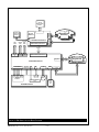
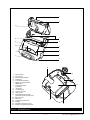
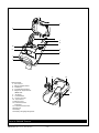

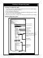
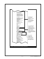
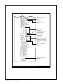
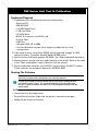
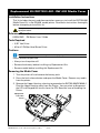
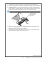
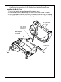
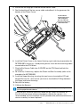
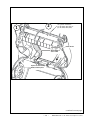
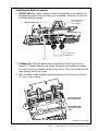
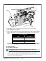
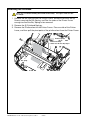
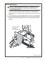
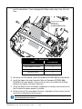
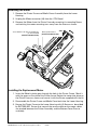
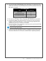
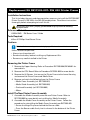
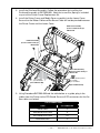
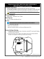
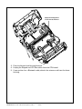
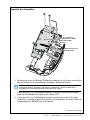
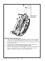
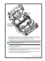
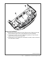
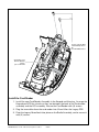
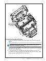
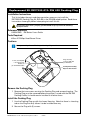
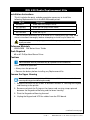
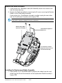
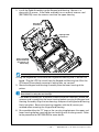
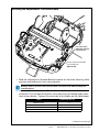
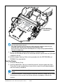
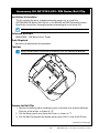
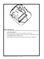
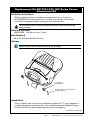
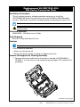
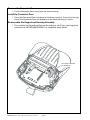
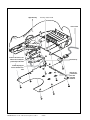
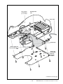
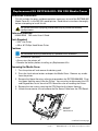
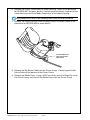
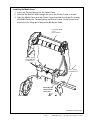
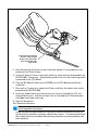
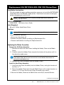
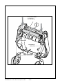
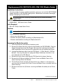
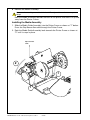
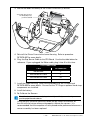
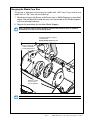
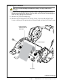
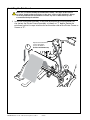
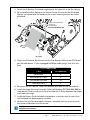
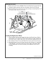
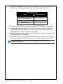
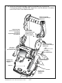
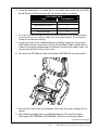
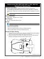
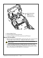
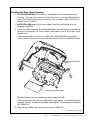
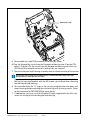
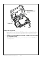
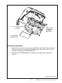
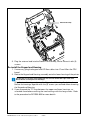
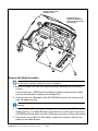
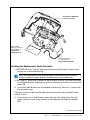
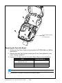
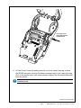
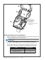
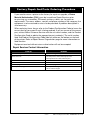
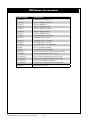
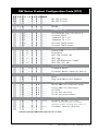
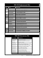
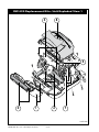
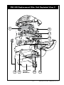
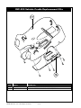
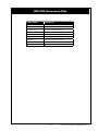
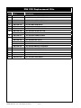
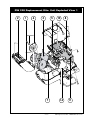
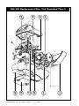


![リレー出力ユニット [ USB2.0 ] ( リレー出力 8 点 ) RLY-8A](http://vs1.manualzilla.com/store/data/006606941_2-b22b191e676e2c0eac3b15163c21303f-150x150.png)