1
__
w
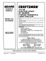
SEARS
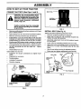
OWNER'S
MANUAL
MODEL NO.
944.609040
CRrlFT$141:IN
o
Caution:
Read and follow
all Safety Rules
and Instruct,ons
Before Operating
Th,s Equipment
14.5 HP
ELECTRIC START
42" MOWER
6 SPEED TRANSAXLE
LAWN TRACTOR
• Assembly
• Operation
• Customer Responsibilities
• Service and Adjustments
• Repair Parts
Sears Canada, Inc., Toronto, Ontario M5B 2B8
I
SAFETY
Practices RULES
for Ride-On
Safe Operation
Mowers
&
IMPORTANT:
THIS CUTTING MACHINE IS CAPABLE OF AMPUTATING HANDS AND FEET AND THROWING OBJECTS.
FAILURE TO OBSERVE THE FOLLOWING SAFETY INSTRUCTIONS
COULD RESULT IN SERIOUS INJURY OR DEATH.
GENERAL
Jq
OPERATION
Ill.
Read, understand, and follow all instructionsin the manual
and on the machine before starting.
Only allow responsible adults, \':_o are familiar with the
instructions, to operate the machine.
Clear the area of objects such as rocks, toys, wire, etc.,
which could be picked up and thrown by the blade.
Be sure the area is clear of other people before mowing. Stop
machine if anyone enters the area.
Never carry passengers.
Do not mow in reverse unless absolutely necessary. Always
look down and behind before and while backing.
Be aware of the mower discharge directionand do not point
it at anyone. Do not operate the mower without either the
entire grass catcher or the guard in place.
Slow down before turning.
Never leave a running machine unattended. Always turn off
blades, set parking brake, stop engine, and remove keys
before dismounting.
Turn off blades when not mowing.
Stop engine before removing grass catcher or unclogging
chute.
Keep children out Ofthe mowing area and under the watchful
care of another responsible adult.
Be alert and turn machine off if children enter the area,
Before _.nd when backing, look behind and down for small
children.
•
Never carry children. They may fall off and be seriously
injured or interfere with safe machine operation.
Never allow children to operate the machine.
Use extra care when approaching blind corners, shrubs,
trees, or other objects that may obscure vision,
IV. SERVICE
Mow only in daylight or good artificial light.
Do not operate the machine while under the influence of
alcohol or drugs.
Watch for traffic when operating near or crossing roadways.
Use extra care when loading or unloading the machine into
a trailer or truck.
II.
•
•
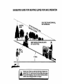
SLOPE OPERATION
•
Slopes are a major factor related to loss-of-control and tipover
accidents, which can result in severe injury or death. All slopes
require extra caution. If you cannotback up the slope or ifyou feel
uneasy on it, do not mow it.
DO:
•
•
•
•
CHILDREN
Tragic accidents can occur if the operator is not alert to the
presence of children. Children are often attracted to the machine
and the mowing activity. Neverassume that children will remain
where you last saw them.
Mow up and down slopes, not across.
Remove obstacles such as recks, tree limbs, etc.
Watch for holes, ruts, or bumps. Uneven terrain could
overturn the machine. Tall grass can hide obstacles.
Use slow speed. Choose a tow gear sothat youwill nothave
to stop or shift while on the slope.
Follow the manufacturer's recommendations for wheel
weights or counterweights to improve stability.
Usa extra care with grass catchers or other attachments.
These can change the stability of the machine.
Keep all movement on the slopes slow and gradual Do not
make sudden changes in speed or direction.
Avoid starting or stopping on a slope. If tires lose traction,
disengage the blades and proceed slowly straight down the
slope.
•
•
Use extra care in handling gasoline and other fuels. They are
flammable and vapors are explosive.
Use only an approved container.
Never remove gas cap or add fuel with the engine
running. Allow engine to cool before refueling. Do not
smoke.
Never refuel the machine indoors.
Never store the machine or fuel container inside where
there is an open flame, such as a water heater.
Never run a machine inside a closed area.
Keep nuts and bolts,especially blade attachment bolts, tight
and keep equipment in good condition.
Never tamper with safety devices. Check their proper
operation regularly.
Keep machine free of grass, leaves, or other debris buUd-up.
Clean oil or fuel spillage. Allow machine to cool before
storing.
Stop and inspect the equipment if you stdke an object.
Repair, if necessary, before restarting.
Never make adjustments or repairs with the engine running.
Grass catcher components are subject to wear, damage, and
deterioration, which could expose moving parts or allow
objects to be thrown. Frequently check components and
replace with manufacturer's recommended parts, when necessary.
Mower blades are sharp and can cut. Wrap the blade(s) or
w_ar gloves, and use extra caution when servicing them.
Check brake operation frequently. Adjust and service as
required.
I
DO NOT:
Do not turn on slopes unless necessary, and then, turn slowly
and gradually downhill, if possible.
Do not mow near drop-offs, ditches, or embankments. The
mower could suddenly turn over if a wheel is over the edge
of a cliff or ditch, or if an edge caves in.
•
Do not mow on wet grass. Reduced traction could cause
sliding.
•
Do not try to stabilize the machine by putting your foot on the
ground.
•
Do not use grass catcher on steep slopes.
Look for this symbol to point out important safety precautions.
It means
CAUTION!I! BECOME ALERT!!! YOUR
SAFETY IS INVOLVED.
CAUTION:
Always disconnect spark
plug wire and place wire where it cannot
contact spark plug in order to prevent
accidental startin_ when setting up,
transporting,
adjusting
or making
repairs.
2
CONGRATULATIONS
on your purchase of a Sears
Tractor. It has been designed, engineered and manufactured to give you the best possible dependability and
performance.
Should you experience any problem you cannot easily
remedy, please contact your nearest Sears Authorized
Service Centre/Department. We have competent, welltrained technicians and the proper tools to Serviceor repair
this tractor.
Please read and retain this manual. The instructionswill
enable you to assemble and maintain your tractorprepedy.
Always observe' the "SAFETY RULES".
MODEL
NUMBER
944.609040
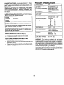
PRODUCT SPECIFICATIONS
HORSEPOWER:
14.5
GASOLINECAPACITY
AND TYPE:
1.25 GALLONS
UNLEADED REGULAR
OIL TYPE (API-SF/SG/SH): SAE 30 (above32°F)
SAE 5W-30 (below32°F)
OIL CAPACITY:
3 PINTS
SPARKPLUG:
SAP: .O3O")
CHAMPION RC12YC
VALVE CLEARANCE:
INTAKE: .003"- .005"
EXHAUST: .005"- .007"
GROUND SPEED (MPH):
FORWARD:
1st
2nd
3rd
4th
5th
6th
REVERSE:
TIRE PRESSURE:
FRONT:
REAR:
CHARGING SYSTEM:
3 AMPS BATTERY
5 AMPS HEADLIGHTS
BATTERY:
AMP/HR:
MIN, CCA:
CASE SIZE:
BLADE BOLT TORQUE:
27-35 FT. LBS.
SERIAL
NUMBER
DATEOFPURCHASE
THEMODELANDSERIALNUMBERSWILLBEFOUND
ON A PLATE UNDER THESEAT.
YOUSHOULDRECORDBOTHSERIALNUMBERAND
DATE OF PURCHASEAND KEEPIN A SAFEPLACE
FOR FUTURE REFERENCE.
MAINTENANCE
AGREEMENT
A Sears Maintenance Agreement is available on this product. Contact your nearest Sears store for details.
CUSTOMER
RESPONSIBILITIES
•
Read and observe the safety rules.
•
Follow a regular schedule in maintaining,cadng for and
using your tractor.
Follow the instructionsunder "Customer Responsibilities" and "Storage" sections of this owner's manual.
•
1.1
1.4
2.2
3.3
4.4
4.9
1.4
14 PSI
12 PSI
25
190
U1R
WARNING:
This tractor is equipped with an internal
combustion engine and should not be used on or near any
unimproved forest-covered, brush-covered or grass-covered land unlessthe engine's exhaust system is equipped
with a spark arrester meeting applicable local or state laws
(if any). Ifa spark arrester is used, it should be maintained
in effective working order by the operator.
A spark arrester for the muffler is available through your
nearest Sears Authorized Service Centre/Department (See
REPAIR PARTS section of this manual).
TABLE OF CONTENTS
SAFETY RULES ............................................................
2
PRODUCT SPECIFICATIONS ...................................... 3
CUSTOMER RESPONSIBILITIES ..................... 3, 14-17
WARRANTY ..................................................................
4
ASSEMBLY ................................................................
6-8
OPERATION .............................................................
9-13
MAINTENANCE SCHEDULE ...................................... 14
LIMITED TWO (2) YEAR WARRANTY
SERVICE AND ADJUSTMENTS ............................ 18-22
STORAGE ...................................................................
23
TROUBLESHOOTING ............................................ 24-25
REPAIR PARTS - TRACTOR ................................. 28-43
REPAIR PARTS- ENGINE .................................... 44-49
PARTS ORDERING/SERVICE ................ BACK COVER
ON CRAFTSMAN
TRACTOR
(RIDING EQUIPMENT)
For Two (2) years from date of purchase Sears Canada, Inc. will repair or replace at Sears option free of charge parts which are
defective as a result of material or workmanship.
FULL ONE (1) YEAR WARRANTY
ON BA'I-FERY
For One (1) year from date of purchase, if any batter! included with this riding equipment proves defective in material or
workmanship and our testing determines the battery will not hold a charge, Sears will replace the battery at no charge.
COMMERCIAL OR RENTAL USE
Warranty on Riding Equipment used for commercial or rental purposes is limitadto ninety (90) days.
This Warranty does NOT cover:
1. Pra-delivery set-up.
2. Tire replacement or repair caused by punctures from outside objects (such as nails, thorns, stumps, or glass)•
3. Expendable items which become worn during normal use, such as blades, spark plug, air cleaners and belts.
4. Repairs necessary because of operator abuse or negligence, including damaged jackshaft or mandrel and the
failure to operate and maintain the equipment according to the instructions contained in the Owner's Manuel.
5. In Home service.
Warranty service is available by returning the Craftsman Riding Equipment to the nearest Sears Service Centre/Department in
Canada. This warranty applies only while this product is in use in Canada.
This warranty is in addition to any statutory warranty and does not exclude or limit legal rights you may have but shall run
concurrently with applicable provincial legislation. Furthermore, some provinces do NOT allow limitationon how long an implied
warranty will last so the above limitationsmay not apply to you.
SEARS CANADA, INC., TORONTO, ONTARIO M5B 2B8
4
CONTENTS
OF HARDWARE
PACK
i
Parts Bag contents
shown full size
Parts packed separately
in carton
Seat
Steedng Boot
(2) Sheet
Metal
Screws
#10-16 x 1/2
@
(1) Large Flat Washer
Steering Wheel
d
(1) Locknut 3/8-24
/
,!
(1) Shoulder Bolt 5/16-18
Manual
Parts Bag
Parts bag contents
not shown full size
m
Steering Wheel
Adapter
©
(1) Knob
@
/
}
'_:_
Steering
Bushing
(1) Washer 17/32 x 1-3/16 x 12 Gauge
(2) Hex Bolts 1/4-20 x 3/4
_j,r
@
(2) 1/4" Keps Nut
Slope Sheet
5
Wheel
Steering
Insert
(2) Keys
ASSEMBLY
Your new tractor has been assembled at the factory with exception of those parts left unassembled for shipping purposes.
To ensure safe and proper operation of your tractor all parts and hardware you assemble must be tightened securely. Use
the correct tools as necessary to insure proper tightness.
TOOLS REQUIRED
FOR ASSEMBLY
STEERING
A socket wrench set will make assembly easier. Standard
wrench sizes are listed.
/_f
WHEEL INSERT
(1) 5/16" wrench
Phillips Screwdriver
(2) 7/16" wrenches
Tire pressure gauge
(1) 1/2" wrench
Utility knife
(1) 9/16" wrench
When right or left hand is mentioned in this manual, it
means when you are in the operating position (seated
behind the steering wheel).
STEERING
TO REMOVE TRACTOR FROM CARTON
UNPACK
•
•
•
t
WHEEL
_
ADAPTER
•
CARTON
'_
TABS
J
Remove all accessible loose parts and parts cartons
from carton (See page 6).
Cut, from top to bottom, along lines on all four corners
of carton, and lay panels flat.
Check for any additional loose parts or cartons and
remove.
1
BEFORE ROLLING TRACTOR OFF SKID
ATTACH
STEERING
SHEET
METAL
SCREW
STEERING
SHAFT
(SHIPPING
POSITION)
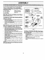
WHEEL (See Fig. 1)
•
•
Slide the steering bushing over the steering shaft,
Raise steering shaft forward until screw holes in dash
line up with steering bushing. Install two (2) sheet
metal screws and tighten securely,
•
Position steering boot over steering shaft.
•
Place tabs of steering boot over tab slots in dash and
push down to secure,
•
Slide steering wheel adapter onto upper steering shaft,
•
Positionfront wheels of the tractor so they are pointing
straight forward.
•
Position steering wheel so cross bars are horizontal
(left to right) and slide onto adapter.
•
Assemble large flat washer and 3/8-24 Iocknut and
tighten securely.
•
Snap steering wheel insert into center of steering
wheel.
•
Remove protective materials from tractor hood and
grill.
IMPORTANT:CHECK FOR AND REMOVE ANY STAPLES
IN SKID THAT MAY PUNCTUR E TIRES WH ERE TRACTOR
IS TO ROLL OFF SKID.
_
," _..=...j
[ _p,,r..
j_---__
....
_
e
"-... : ..........
:;:
''
,,,
" :'
--
TAB SLOT
FIG. 1
TO ROLL TRACTOR OFF SKID (See Operation section, page 10, for location and function of controls)
•
•
•
•
•
6
Press liftlever plunger and raise attachment lift lever to
its highest position.
Release parking brake by depressing clutch/brake
pedal.
Place gearshift lever in neutral (N) position.
Roll tractor forward off skid.
Remove banding holding discharge guard up against
tractor,
ASSEMBLY
HOW TO SET UP YOUR TRACTOR
CONNECT
BA'n'ERY
(See Figs. 2 and 3)
CAUTION: Do not short battery terminals by allowing a wrench or any other
object to contact both terminals at the
same time. Before connecting battery,
remove metal bracelets, wristwatch
bands, rings, etc.
BOXDOOR
Positive terminal must be connected
first to prevent sparking from accidental grounding.
•
Remove cardboard packing from seat pan and liftseat
pan to raised position.
•
Open battery box door and remove protective plastic•
•
Remove terminal protective caps and discard,
•
If this battery is put into service after month and year
indicated on label (label located between terminals)
charge battery for minimum of one hour at 6-10 emps.
•
FIG. 3
INSTALL
Connect BLACK grounding cable to negative (-) terminal with remaining hex bolt and keps nut. Tighten
securely,
•
Close battery box door.
Open battery box door for:
•
•
•
Remove cardboard packing on seat pan.
Place seat on seat pan and assemble shoulder bolt.
Tighten shoulder bolt securely.
•
Assemble adjustment knob and flat washer loosely.
Do not tighten.
•
•
Lower seat into operating position and sit on seat.
Slide seat untilacomfortable position is reached which
allows you to press clutch/brake pedal all the way
down.
•
Get off seat without moving its adjusted position.
•
Raise seat and tighten adjustment knob securely.
Inspection for secure connections (to tighten hardware).
•
Inspection for corrosion.
•
Testing battery.
•
Jumping (if required).
•
Periodic charging.
(See Fig. 4)
Adjust seat before tightening adjustment knob.
First connect RED battery cable to positive (+) terminal
with hex bolt and keps nut as shown• Tighten securely.
•
SEAT
SEATPAN
SEAT
SHOULDER
BOLT
TERMINAL
PROTECTIVE
CAPS
ISCARD
_
'
I
KEPS
NUT _
i
i
HEX BOLT
POSITIVE (RED)
CABLE
• FLAT WASHER
A_DJUSTMENT
KNOB
FIG. 4
NEGATIVE
(BLACK)
CABLE
FIG. 2
7
ASSEMBLY
CHECK
TIRE
#'CHECKLIST
PRESSURE
The tires on your tractor were overinflated at the factory for
shipping purposes. Correct tire pressure is important for
best cutting performance,
•
Reduce tire pressure to PSI shown in =PRODUCT
SPECIFICATIONS" on page 3 of this manual.
CHECK
DECK
LEVELNESS
For best cuffing results, mower housing shoutd be propedy
leveled. See "TO LEVEL MOWER HOUSING" in the
Service and Adjustments sect'_onof this manual
CHECK
BELTS
FOR
PROPER
POSITION
OF
ALL
See the figures that are shown for replacing motion and
mower blade drive belts in the Service and Adjustments
section of this manual. Verify that the belts are routed
correctly.
BEFORE YOU OPERATE AND ENJOY YOUR NEW
TRACTOR, WE WISH TO ASSURE THAT YOU RECEIVE
THE BESTPERFORMANCE AND SATISFACTION FROM
THIS QUALITY PRODUCT.
PLEASE REVIEW THE FOLLOWING CHECKLIST:
,/
All assembly instructionshave been completed.
/
No remaining loose parts in carton.
,/
Battery is properly prepared and charged. (Minimum
1 hour at 6 amps).
•/
Seat is'adjusted comfortably and tightened securely.
,/
All tires are properly inflated. (For shipping purposes,
the tires were ovennflated at the factory).
,/
Be sure mower deck is properly leveled side-to-side/
front-to-rear for best cutting results. (Tires must be
propedy inflated for levet(ng).
,/
Check mower and drive belts. Be sure they are routed
properly arour'_ pulleys and inside all belt keepers.
CHECK BRAKE SYSTEM
,/
Check wiring. See that all connections are still secure
and wires are properly clamped.
WHILE LEARNING HOW TO USE YOUR TRACTOR, PA Y
EXTRA ATTENTION TO THE FOLLOWING IMPORTANT
ITEMS:
After you leem how to operate your tractor, check to see
that the brake is properly adjusted. See "TO ADJUST
BRAKE" in the Service and Adjustments section of this
manual.
/
Engine oil is at proper level.
/
Fuel tank is filled with fresh, clean, regular unleaded
gasoline.
Become familiar with all controls - their location and
function. Operate them before you start the engine.
,/
/
8
Be sure brake system is in safe operating condition.
OPERATION
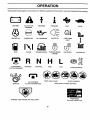
These symbols may appear on your product or in literature supplied with the product. Learn and understand their meaning.
BATTERY
CAUTION OR
WARNING
ENGINE ON
ENGINE OFF
OIL PRESSURE
LIGHTS ON
FUEL
CHOKE
MOWER HEIGHT
PARKING BRAKE
LOCKED
REVERSE
FORWARD
FAST
SLOW
UNLOCKED
MOWER LIFT
R N H L
ATTACHMENT
CLUTCH ENGAGED
IGNITION
DANGER,
REVERSE
NEUTRAL
ATTACHMENT
CLUTCH DISENGAGED
HIGH
LOW
PARKING BRAKE
KEEP AREA CLEAR
SLOPE HAZARDS
(SEE SAFETY RULES SECTION)
FREE WHEEL
KEEP HANDS AND FEET AWAY
(Automatic Models only)
9
OPERATION
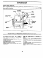
KNOW YOUR TRACTOR
READ THIS OWNER'S
MANUAL
"_
AND SAFETY RULES BEFORE
OPERATING
YOUR TRACTOR
Compare theillustrations with yourtractor to familiarize yourself withthelocationsof variouscontrols and adjustments. Save
this manual for future reference.
AMMETER
ATTACHMENT
CLUTCH LEVER
UGHT
IGNITION
SWITCH
"'"
THRO'I-rLE/CHO
CONTROL
UFTLEVER
PLUNGER
KE
ATTACHMENT
LIFT LEVER
MOWER DECK
HEIGHT ADJUSTMENT
POSITIONS
CLUTCH/BRAKE
PEDAL
PARING
BRAKE
GEARSHIFT
LEVER
FIG. 5
Our tractors conform to the safety standards of the American National Standards Institute.
ATTACHMENT CLUTCH LEVER: Used to engage the
mower blades, or other attachments mounted to your
tractor.
AMMETER:
battery.
Indicates charging (+) or discharging (-) of
GEARSHIFT LEVER: Selects the speed and direction of
tractor.
LIGHT SWITCH: Turns the headlights on and off.
THROTTLE/CHOKE CONTROL: Used for starting and
controningengine speed.
ATTACHMENT LIFT LEVER: Used to raise, lower, and
adjust the mower deck or other attachments mounted to
your tractor.
LIFT LEVER PLUNGER: Used to release attachment lift
lever when changing its position.
CLUTCH/BRAKE PEDAL: Used fordeclutchingandbraking the tractor and starting the engine.
PARKING BRAKE: Locks clutch/brake pedal into the
brake position.
IGNITION SWITCH:
engine.
10
Used for starting and stopping the
OPERATION
The operation of any tractor can result in foreign objects thrown Into the eyes, which
can result In severe eye damage. Always wear safety glasses or eye shields while
operating your tractor or performing any adjustments or repairs. We recommend a wide
vision safety mask over spectacles or standard safety glasses.
HOW TO USE YOUR TRACTOR
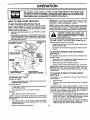
TO SET PARKING
BRAKE (See Fig. 6)
Your tractor isequipped with an operator presence sensing
switch. When engine is running, any attempt by the
operator to leave the seat without first setting the parking
brake will shut off the engine.
•
Depress clutcWbrake pedal into full"BRAKE" position
and hold.
•
Place parking brake lever in "ENGAGED" positionand
release pressurefrom clutclVorakepedal. Pedal should
remain in "BRAKE" position. Make sure parking brake
will hold tractor secure.
IMPORTANT: LEAVING THE IGNITION SWITCH IN ANY
POSITION OTHER THAN "OFF" WILL CAUSE THE
BATTERY TO BE DISCHARGED, (DEAD).
NOTE: Under certain conditionswhen tractor is standing
idlewith the engine running,hot engine exhaust gases may
cause =browning" of grass. To eliminate this possibility,
always stop engine when stopping tractor on grass areas.
I&
TO USE THRO'n'LE
"DISENGAGED =
POSITION
ATTACHMENT CLUTCH LEVER
"ENGAGED" POSITION
(See Fig. 6)
•
Operating engine at less than full throttle reduces the
battery charging rate.
•
Full throttle offers the best bagging and mower performance.
TO MOVE FORWARD
(See Fig. 6)
PARING
BRAKE
"ENGAGED"
-POSmON
"BRAKE"
POSITION
CONTROL
I
Always operate engine at full throttle.
KEY
THROTTLE/CHOKE',
CONTROL LEVER
pletely, as described above, before leaving the operator's position; to empty
AUTIbN:
Always
grass
catcher,
etc. stop tractor com-
AND BACKWARD
The direction and speed of movement is controlled by the
gearshift lever.
SHIFT
LEVER
•
Start tractor with clutch/brake pedal depressed and
gearshift lever in neutral (N) position.
•
Move gearshift lever to desired position.
Slowly release clutch/brake pedal to start movement.
IMPORTANT: BRING TRACTOR TO A COMPLETE STOP
BEFORE SHIFTING OR CHANGING GEARS, FAILURE
TO DO SO WILL SHORTEN THE USEFUL LIFE OF YOUR
TRANSAXLE.
CLUTCH/BRAKE PEDAL
"DRIVE"POSITION
PARKING BRAKE
"DISENGAGED'POSITION
TO ADJUST MOWER CU'I-FING HEIGHT
(See Fig. 6)
FIG. 6
STOPPING
The position of the attachment lift lever determines the
cutting height.
•
Grasp lift lever.
(See Fig. 6)
MOWER BLADES ,
To stop mower blades,move attachment clutchlever to
=DISENGAGED" position.
GROUND DRIVE •
•
The cutting height range is approximately 1-1/2 to 4". The
heights are measured from the ground to the blade tip with
the engine not running. These heights are approximate
and may vary depending upon soil conditions, height of
grass and types of grass being mowed,
•
The average lawn shouldbe cut to approximately 2-1/2
inches during the cool season and to over 3 inches
during hot months. For healthier and better looking
lawns, mow often and after moderate growth.
To stop ground drive, depress clutch/brake pedal into
full BRAKE position.
•
Move gearshift lever to neutral (N) position.
ENGINE •
Move throttle control to slow position.
NOTE: Failure to move throttle control to slow position and
allowing engine to idle before stopping may cause engine
to "backfire".
•
Turn ignition key to "OFF" position and remove key.
Always remove key when leaving tractor to prevent
unauthorized use.
•
Never use choke to stop engine.
Press plunger with thumb and move lever to desired
position.
•
11
For best cutting performance, grass over 6 inches in
height should be mowed twice. Make the first cut
relatively high; the second to desired height,
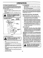
OPERATION
TO OPERATE
MOWER
TO TRANSPORT
(See Fig. 7)
Your tractor isequipped with an operator presence sensing
switch. Any attempt by the operator to leave the seat with
the engine runningand the attachment clutchengaged will
shut off the engine.
•
•
Select desired height of cut.
Start mower blades by engaging attachment clutch
control.
TO STOP MOWER BLADES - disengage attachment
clutch control.
•
•
Raise atts,chment lift to highest position with attachment lift control.
•
When pushing or towing yourtractor, be sure geamhitt
lever is in neutral (N) position.
•
Do not push or tow tractor at more than five (5) MPH.
NOTE: To protect hood from damage when transporting
yourtractoron atruckoratrailer, be sure hood isclosed and
secured totractor. Use an appropriate means oftying hood
to tractor (rope, cord, etc.).
BEFOR'E STARTING THE ENGINE
without either the entire grass catcher,
CAUTION:
operate or
thethe
mower
on
mowers Do
so not
equipped,
discharge guard in place.
ATTACHMENTCLUTCHLEVER
"DISENGAGED"POSmON
"ENGAGED"
POSITION
CHECK ENGINE'OIL
ATTACHMENT
LIFT LEVER
HIGH POSITION
LEVEL (See Fig. 12)
•
The engine in your tractor has been shipped, from the
factory, already filled with summer weight oil.
•
Check engine oilwith tractor on level ground.
•
Remove oil fillcap/dipstickand wipe clean, reinsertthe
dipstick and screw cap tight, wait for a few seconds,
remove and read oil level. If necessary, add oil until
"FULL" mark on dipstick is reached. Do not overfill.
•
For cold weather operation you should change oil for
easier starting (See "OIL VISCOSITY CHART" in the
Customer Responsibilities section of this manual).
•
To change engine oil, see the Customer Responsibilities section in this manual.
ADD GASOLINE
•
Fill fuel tank. Use fresh, clean, regular unleaded
gasoline with a minimum of 87 octane. (Use of leaded
gasoline will increase carbon and lead oxide deposits
and reduce valve life). Do not mix oil with gasoline.
Purchase fuel in quantities that can be used within 30
days to assure fue_freshness.
IMPORTANT: WHEN OPERATING IN TEMPERATURES
BELOW 32°F(0°C), USE FRESH, CLEAN WINTER GRADE
AtsrOL NE TL_ HELP INSURE GOOD COLD WEATHER
STARTING.
DISCHARGE
FIG. 7
TO OPERATE
I
WARNING: Experience indicates that alcohol blended
fuels (called gasohol or using ethanol or methanol) can
attract moisture which leads to separation and formation of
acids during storage. Acidic gas can damage the fuel
system of an engine while in storage. To avoid engine
problems, the fuel system should be emptied before storage of 30 days or longer. Drain the gas tank, start the
engine and let it run until the fuel lines and carburetor are
empty. Use fresh fuel next season. See Storage Instructions for additional information.
Never use engine or
carburetor cleaner products in the fuel tank or permanent
damage may occur.
ON HILLS
|
hills with slopes greater than 15° and
CAUTION:
not drive
up or down
do not drive Do
across
any slope.
I
|
Choose the slowest speed before starting up or down
hills.
•
•
Avoid stopping or changing speed on hills.
If slowing is necessary, move throttle control lever to
slower position.
If stopping is absolutely necessary, push clutch/brake
pedal quickly to brake position and engage parking
brake,
°
Move gearshift lever to 1st gear. Be sure you have
allowed room for tractor to roll slightly as you restart
movement.
•
To restart movement, slowly release parking brake and
clutch/brake pedal.
Make all turns slowly.
IAC, to
TO.
o"o
I
filler neck. Do not overfill. Wipe off any
spilled oil or fuel. Do not store, spill or
use gasoline near an open flame.
12
OPERATION
TO START ENGINE (See Fig. 6)
MOWING TIPS
When starting the engine for the first time or if the engine
has run out of fuel, it will take extra cranking time to move
fuel from the tank to the engine.
•
•
Sit on seat in operating position, depress clutch/brake
pedal and set parking brake.
•
•
Place gear shift lever in neutral (N) position.
Move attachment clutch to =DISENGAGED" position.
•
Move throttle control to choke position.
Mower should be propedy leveled for best mowing
performance. See "TO LEVEL MOWER HOUSING" in
the Service and Adjustments section of this manual.
The left hand side of mower should be used for trimming.
Drive so that clippings are discharged onto the area
that has been cut. Have the cut area to the right of the
machine. This will result in a more even distribution of
clippings and more uniform cutting.
NOTE: Before starting, read the warm and cold starting
procedures below.
•
Insertkeymtolgnltionandtumkeyclockwlseto"START"
position and release key as soon as engine starts. Do
not run starter continuously for more than fifteen seconds per minute, if the engine does not start after
several attempts, move throttle controlto fast position,
wait a few minutes and try again. If engine still does not
start, move the throttle control back to the choke
position and retry.
When mowing large areas, start by turning to the right
so that clippings will discharge away from shrubs,
fences, driveways, etc. After one ortwo rounds, mow
in the opposite direction making left hand turns until
finished (See Fig. 8).
If grass is extremely tall, it should be mowed twice to
reduce load and possible fire hazard from dded clippings. Make first cut relatively high; the second to the
desired height.
WARM WEATHER STARTING (50 ° F and above)
•
•
Tire cha,ins cannot be used when the mower housing
is attached to tractor.
When engine starts, move the throttle controltothe fast
position.
The attachments and ground drive can now be used. If
the engine does not accept the load, restart the engine
and allow it to warm up for one minute using the choke
as described above.
Do not mow grass when it is wet. Wet grass will plug
mower and leave undesirable clumps. Allow grass to
dry before mowing.
Always operate engine at full 'throttle when mowing to
assure better mowing performance and proper discharge of material. Regulate ground speed by selecting a low enough gear to give the mower cutting
performance as well as the quality of cut desired.
COLD WEATHER STARTING ( 50 ° F and below)
•
When engine starts, allow engineto run with the throttle
control in the choke position until the engine runs
roughly, then move throttle control to fast position. This
may require an engine warm-up period from several
seconds to several minutes, depending on the temperature.
•
The attachments can also be used during the engine
warm-up period.
NOTE: If at a high altitude (above 3000 feet) or in cold
temperatures (below 32 F) the carburetor fuel mixture may
need to be adjusted for best engine performance. See "TO
ADJUST CARBURETOR" in the Service and Adjustments
section of this manual.
When operating attachments, select a ground speed
that will suit the terrain and give best performance of
the attachment being used.
FIG. 8
13
CUSTOMER
RESPONSIBILITIES
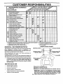
.A..TENA.CESC.EOUL
AS YOU COMPLETE
REGULAR SERVICE
dl#_
Check
Check BrakeOperation
Tire Pressure
Check OperatorPresenceand
I
__/_._/_._"
_51:HVlC.F DATES
_
T
InterlockSystems
Check for LooseFasteners
T
LubricationChart
Check
BatteryLevel
Sharpen/Replace
MowerBlades
Clean Batteryand Terminals
_s4
R
Check TransaxleCooling
t_'
V'7
V _
I_
AdjustBladeBelt(s)Tension
MotionDrive Belt(s) Tension
Ills
VPs
Adjust
Check EngineOil Level
Change
Engine
If
V*
Oil
_1.2,3
E
N
Clean Air Filter
Clean AirScreen
G
InspectMuffier/SparkArrester
NI
Replace Oil Filter(If
Vw2
If=
1_1,2
V'2
If
1_
equipped)
E i Clean EngineCoolingFins
ReplaceSpark Plug
ReplaceAir FilterPaperCartridge
ReplaceFuel Filter
12 g4-
If
Change more often when operating under a heavy _ad or in high ambient temperatures.
Service more often when operating in dirty or dusty conditions.
If equipped with oil filter, change oil every 50 hours.
Replace blades more often when mowing in sandy soil.
GENERAL
l##
5 * If equipped with adjustable system.
6 - NOt required if equipped with malntartance-free
batter,/.
7 - Tighten front axle pivot bolt to 35 ft.-Ibs, maximum.
DO not overtightan.
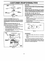
LUBRICATION
RECOMMENDATIONS
The warranty on this tractor does not cover itemsthat have
been subjected to operator abuse or negligence. To
receive full value from the warranty, operator must maintain tractor as instructed in this manual.
CHART
®
®
®
BEARING
ZERK
" FRONT WHEEL ®
BEARING ZERK
Some adjustments will need to be made periodically to
properly maintain your tractor.
®
All adjustments in the Service and Adjustments section of
this manual should be checked at least once each season.
Once a year you should replace the spark plug, clean
or replace air _ter, and check blades and belts for
wear. A new spark plug and clean air filter assure
properair-fuel mixture and help your engine run better
and last longer.
BEFORE
•
•
(_
CLUTCH
PIVOT(S)
EACH USE
Check engine oil level.
Check brake operation,
•
Check tire pressure.
•
Check operator presence and
•
interlock systems for proper operation.
Check for loose fasteners,
®SAE
14
30 OR 10W30 MOTOR OIL
®
GENERAL PURPOSE GREASE
®
REFER TO CUSTOMER RESPONSIBILITIES
"ENGINE"
SECTION
IMPORTANT:
CO NOT OIL OR GREASE THE PIVOT POINTS
WHICH HAVE SPECIAL NYLON BEARINGS.
VISCOUS LUBRICANTS WILL ATTRACT DUST AND DIRT THAT WILL SHORTEN
THE LIFE OF THE SELF-LUBRICATING
BEARINGS.
IF YOU
FEEL THEY MUST BE LUBRICATED,
USE ONLY A DRY, POWDERED GRAPHITE TYPE LUBRICANT SPARINGLY.
CUSTOMER
RESPONSIBILITIES
TRACTOR
TRAILING
EDGE UP
Always observe safety rules when performingany maintenance.
MANDREL
ASSEMBLY
BLADE
BRAKE OPERATION
If tractor requires more than six (6) feet stopping distance
at high speed in highest gear, then brake mustbe adjusted.
(See "TO ADJUST BRAKE" in the Service and Adjustments section of this manual).
FLAT WASHEF
LOCK WASHER
TIRES
•
Maintain proper air pressure in all tires (See "PRODUCT SPECIFICATIONS" on page 3 of this manual).
•
Keep tires free of gasoline, oil, or insect controlchemicals which can harm rubber.
•
Avoid stumps, stones, deep ruts, sharp objects and
other hazards that may cause tire damage.
_-,,
*A GRADE 8 HEAT TREATED BOLT CAN BE
IDENTIRED BY SIX LINES ON THE BOLT HEAD
FIG. 9
TO SHARPEN
NOTE: To seal tire punctures and prevent flat tires due to
slow leaks, tire sealant may be purchased from your local
parts dealer. Tire sealant also prevents tire dry rot and
corrosion.
OPERATOR
PRESENCE
•
The engine shouTdnot start unless the clutch/brake
pedal is fully depressed and attachement clutch control is in the disengaged position.
When the engine is running,anyattempt bythe operator to leave the seat without first setting the parking
brake should shut off the engine.
When the engine is running and the attachment clutch
is engaged, any attempt by the operator to leave the
seat should shut off the engine.
•
The attachment clutch should never operate unless
the operator is in the seat.
BLADE
(See Fig. X2)
Care should be taken to keep the blade balanced. An
unbalanced blade will cause excessive vibration and eventual damage to mower and engine.
SYSTEM
•
BLADE
NOTE: We do not recommend sharpening blade - but ifyou
do, be sure the blade is balanced.
Be sure operator presence and interlock systems are
working properly. If your tractor does not function as
described, repair the problem immediately,
•
HEX BOLT (GRADE 8)*
•
The blade can be sharpened with a file or on a grinding
wheel. Do not attempt to sharpen while on the mower.
•
To check blade balance, you will need a 5/8" diameter
steel bolt, pin, or a cone balancer. (When using a cone
balancer, follow the instructions supplied with balancer.)
NOTE: Do not use a nail for balancing blade. The lobes of
the center hole may appear to be centered, but are not.
•
Slide blade on to an unthreaded portion of the steel bolt
or pin and hold the bolt or pin parallel with the ground.
If blade is balanced, it should remain in a horizontal
position. If either end of the blade moves downward,
sharpen the heavy end until the blade is balanced.
CENTER HOLE
CARE
/
/
For best results mower blades must be kept sharp, Replace bent or damaged blades,
BLADE
REMOVAL
o 5/8" BO_
(See Fig. 9-)
•
Raise mower to highest position to allow access to
blades.
•
Remove hex bolt, lock washer and flat washer securing blade.
•
Install new or resharpened blade with trailing edge up
towards deck as shown.
BLADE
OR PIN _
BA'I-rERY
IMPORTANT:
TO ENSURE
PROPER
ASSEMBLY,
CENTER HOLE IN BLADE MUST ALIGN WITH STAR ON
MANDREL ASSEMBLY.
FIG. 10
Your tractor has a battery charging system which is sufficient for normal use. However, periodic charging of the
battery with an automotive charger will extend its life.
•
Keep battery and terminals clean.
Reassemble hex bolt, lock washer and flat washer in
exact order as shown.
•
Tighten bolt securely (27-35 Ft. Lbs. torque).
IMPORTANT: BLADE BOLT IS GRADE 8 HEAT TREATED.
Keep battery bolts tight.
15
•
Keep small vent holes open.
•
Recharge at 6-10 amperes for 1 hour.
CUSTOMER RESPONSIBILITIES
TO CLEAN BATTERY AND TERMINALS
Corrosionand dirton the battery and terminals can cause the
battery to "leak" power.
Open battery box door.
•
Disconnect BLACK battery cable first then RED battery
cable and remove battery from tractor.
•
Rinse the battery with plain water and dry.
•
Clean terminals and battery cable ends with wire brush
until bdght.
Coat terminals with grease or petroleum jelly.
•
•
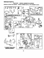
After oil has drained completely, replace oil drain plug
and tighten securely.
•
Refill engine with oilthrough oil fill dipstick tube. Pour
slowly. Do not overfill. For approximate capacity see
=PRODUCT SPECIFICATIONS
on page 3 of this
manual.
•
Use gauge on oil fill cap/dipstick for checking level. Be
sure dipstick cap is tightened securely for accurate
reading. Keep oil at "FULL" line on dipstick.
Reinstall battery (See "CONNECT BATTERY" in the
Assembly section of this manual).
CAP/DIPSTICK
V-BELTS
Check V-belts for deterioration and wear after 100 hours of
operation and replace if necessary. The belts are not
adjustable. Replace belts if they begin to slip from wear.
TRANSAXLE
COOLING
OIL DRAIN PLUG
Keep transaxle free from build-up of dirt and chaff which
can restrictcooling.
ENGINE
FIG. 11
LUBRICATION
AIR FILTER (See Fig. 12)
Only use high quality detergent oil rated with APt service
classification SF, SG or SH. Select the oil's SAE viscosity
grade according to your expected operating temperature.
SAE VISCOSITY
o"
.30*
-20°
TEMPERATURE
30"
.10 °
GRADES
32" 40"
0°
RANGE ANTICIPATED
Your engine will not run properly using a dirty air filter.
Clean the foam pre-cleaner after every 25 hours of operation or every season. Service paper cartridge every 100
hours of operation or every season, whichever occursfirst.
Service air cleaner more often under dusty conditions.
Remove knob(s) and cover.
TO SERVICE PRE-CLEANER
60"
10_
8_
200
•
Slide foam pre-cleaner off cartridge.
30°
Wash it in liquid detergent and water.
BEFORE NEXT OIL CHANGE
NOTE: Although multi-viscosity oils (5W30, 10W30 etc.)
improve starting in cold weather, these multi-viscosityoils
will result in increased oil consumption when used above
32°F. Check your engine oil level more frequently to avoid
possible engine damage from running low on oil.
•
Squeeze it dry in a clean cloth.
•
Saturate it in engine oil. Wrap it in clean, absorbent
cloth and squeeze to remove excess oil.
•
If very dirty or damaged, replace pre-cleaner,
•
Reinstall pre-cleaner over cartridge.
•
Reinstall cover and secure with knob(s).
TO SERVICE CARTRIDGE
Change the oil after every 25 hours of operation or at least
once a year ifthe tractor isnot used for 25 hours in one year.
Check the crankcase oil level before starting the engine
and after each eight (8) hours of operation. Tighten oil fill
cap/dipstick securely each time you check the oil level.
•
Remove cartridge nut.
•
Carefully remove cartridge to prevent debris from entering carbure_ _r. Clean base carefully to prevent
debris from entering carburetor.
TO CHANGE ENGINE OIL (See Fig. 11)
•
Cleancartridgebytappinggentlyonflatsurface.
Ifvery
dirty or damaged, replace cartridge.
Reinstall cartridge, nut, precleaner, cover and secure
with knob(s).
IMPORTANT:
PETROLEUM SOLVENTS, SUCH AS
KEROSENE, ARE NOT TO BE USED TO CLEAN THE
CARTRIDGE. THEY MAY CAUSE DETERIORATION OF
THE CARTRIDGE. DO NOT OIL CARTRIDGE. DO NOT
USE PRESSURIZED
AIR TO CLEAN OR DRY
CARTRIDGE.
Determine temperature range expected before oil change.
All oil must meet API service classification SF, SG or SH.
•
Be sure tractor is on level surface.
•
Oil will drain more freely when warm.
Catch oil in a suitable container.
•
Remove oilfill cap/dipstick. Be careful not to allow dirt
to enter the engine when changing oil
•
Remove drain plug.
16
CUSTOMER
RESPONSIBILITIES
MUFFLER
Inspect and replace corroded mufflerend spark arrester (if
equipped) a_ it could create a fire hazard and/or damage.
CARTRIDGE
NUT
SPARK PLUGS
Replace spark plugs at the beginning of each mowing
season or after every 100 hcurs of operation, whichever
occurs first. Spark plug type and gap setting are shown in
"PRODUCT SPECIFICATIONS" on page 3 of this manual.
'APER
FOAM
PRE-CLEAN|
IN-LINE
_BASE
CARTRIDGE
FIG. 12
CLEAN
AIR SCREEN
(See Fig. 13)
Air screen must be kept free of dirt and chaff to prevent
engine damage from overheating. Clean with a wire brush
or compressed air to remove dirt and stubborn dried gum
fibers.
ENGINE
COOLING
FILTER
(See
Fig. 14)
•
With engine cool, remove filter and plug fuel line
sections.
•
Place new fuel filter in position in fuel line with arrow
pointing towards carburetor.
•
Be sure there are no fuel line leaks and clamps are
propedy positioned.
•
Immediately wipe up any spilled gasoline.
FINS (See Fig. 13)
CLAMP
Remove any dust, dirt or oil from engine cooling fins to
prevent engine damage from overheating.
•
Remove screws from blower housing and lift housing
and dipstick tube assembly off engine.
•
Cover oil fill opening to prevent entry of dirt.
•
Use compressed air or stiff bristle brush to thoroughly
clean engine cooling fins.
•
To reassemble, reverse above procedure.
SCREWS
FUEL
The fuel filter shouldbe replaced once each season. If fuel
filter becomes clogged, obstructingfuel flow to carburetor,
replacement is required,
CLAMP
FUEL
_
FILTER--
//
_J_..Z._._.__J
FIG. 14
CLEANING
BLOWER HOUSING
SCREWS
AIR SCREEN
•
Clean engine, battery, seat, finish, etc. of all foreign
matter.
•
Keep finished surfaces and wheels free of all gasoline,
oil, etc.
•
Protect painted surfaces with automotive type wax.
We do not recommend using a garden hose to clean your
tractor unless the electrical system, muffler, air filter and
carburetor are covered to keep water out. Water in engine
can result in a shortened engine life.
DIPSTICK TUBE
ASSEMBLY
I
ENGINE COOLING FINS
SPARK
PLUG
FIG. 13
17
SERVICE AND ADJUSTMENTS
CAUTION:
•
•
•
•
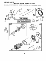
TO REMOVE
BEFORE PERFORMING ANY SERVICE OR ADJUSTMENTS:
Depress clutch/brake pedal fully and set parking brake.
Place gearshift lever in neutral (N) position.
Place attachment clutch In "DISENGAGED" position.
Turn Ignltlon key "OFF" and remove key.
Make sure the biades and all moving parts have completely stopped,
Disconnect spark plug wire from spark plug and place wire where it cannot come in contact with
plug.
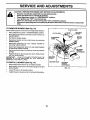
MOWER (See Fig. 15)
CLUTCH LEVER
Mower willbe easier to remove from the rightside oftractor.
•
•
•
Place attachment clutch in "DISENGAGED" position.
Move attachment lift lever forward to lower mower to its
lowest position.
Roll belt off engine pulley.
•
Disconnect clutch rod from clutch lever by removing
retainer spring.
•
Disconnect anti-sway bar from chassis bracket by
removing retainer spring.
•
Disconnect suspension arms from rear deck brackets
by removing retainer springs.
•
Disconnect front links from deck by removing retainer
spnngs.
RETAINER
CLUTCH ROD
ENGINE
PULLEY
SUSPENSION
ARMS
SPRINGS
•
Raise lift lever to raise suspension arms. Slide mower
out from under tractor.
IMPORTANT:
IF AN ATTACHMENT OTHER THAN THE
MOWER IS TO BE MOUNTED TO THE TRACTOR,
REMOVED THE FRONT LINKS.
RETAINER
SPRING
ANTI-SWAY BAR
TO INSTALL
MOWER
(See Fig. 15)
•
Raise attachment lift lever to its highest position.
Slide mower under tractorwith discharge guard to right
side of tractor.
•
Lower lift lever to its lowest position.
•
Install mower in reverse order of removal instructions.
RETAINER
SPRINGS
(BOTH SIDES)
FIG. 15
18
SERVICE AND ADJUSTMENTS
TO LEVEL MOWER HOUSING
FRONT-TO-BACK
ADJUSTMENT
(See Figs. 18 and 19)
IMPORTANT=
DECK MUST BE LEVEL SIDE-TO-SIDE.
IF
THE FOLLQWlNG
FRONT-TO-BACK
ADJUSTMENT
IS
NECESSARY, BE SURE TO ADJUST BOTH FRONT LINKS
EQUALLY
SO MOWER
WILL STAY LEVEL SIDE-TOSIDE.
Adjust the mower while tractor is parked on level ground or
driveway. Make sure tires are propedy inflated (See
=PRODUCT SPECIFICATIONS" on page 3 of this manual).
Iftires are over or underinflated, you willnot properlyadjust
your mower.
To obtain the best cutting results, the mower housing
should be adjusted so that the front is approximately 1/8" to
1/2" lower than the rear when the mower is in its highest
position.
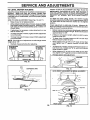
SIDE-TO-SIDE ADJUSTMENT (See Figs. 16 and 17)
•
Raise mower to its highest position.
•
At the midpointof both sides of mower, measure height
from bottomedge of mower to ground. Distance "A" on
both sides of mower should be the same or within 1/4"
of each other.
•
If adjustment is necessary, make adjustment on one
side of mower only.
To raise one side of mower, tighten liftlink adjustment
nut on that side.
•
•
Check adjustment on right side of tractor. Measure distance "D" directly in front and behind the mandrel at bottom
edge of mower housing as shown.
To lower one side of mower, loosen lift link adjustment
nut on that side.
NOTE: Each full turn of adjustment nut will change mower
height about 1/8".
•
Recheck measurements after adjusting.
BOTTOM EDGE
OF MOWER
TO GROUND
•
Before making any necessary adjustments, check that
both front links are equal in length. Both links should be
approximately :10-3/8".
•
If links are not equal in length, adjust one link to same
length as other link.
•
To lower front of mower loosen nut =E" on both front
links an equal number of turns.
•
When distance "D" is 1/8" to 1/2" lower at front than
rear, tighten nuts =F" against trunnion on both front
links.
To raise front of mower, loosen nut"F" from trunnionon
both front links. Tighten nut "E" on both front links an
equal number of turns.
When distance "D" is 1/8" to 1/2" lower at front than
rear, tighten nut"F"against trunnionon bothfrontlinks.
BOTTOM EDGE
OF MOWER
TO GROUND
Recheck side-to-side adjustment.
GROUND LINE
FIG. 16
SUSPENSION
FIG. 18
ARM
BOTH FRONT LINKS MUST BE EQUAL IN LENGTH
,.?.:....
LIFT LINK
ADJUSTMENT
NUT
.._.,_._
NUT "E"
FIG. 17
FRONT LINKS
19
TRUNNION
FIG. 19
SERVICE AND ADJUSTMENTS
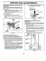
TO REPLACE
(See Fig. 20)
MOWER
BLADE DRIVE BELT
WITH PARKINGBRAKE *ENGAGED"
The mower blade drive belt may be replaced without tools.
Park the tractor on level surface. Engage parking brake.
BELT REMOVAL
•
Remove mower from tractor (See "TO REMOVE
MOWER" in this section of this manual).
•
Work belt off both mandrel pulleys and idler pulleys.
•
Pull belt away from mower.
BELT INSTALLATION
•
Install new belt in reverse order of removal.
•
Make sure belt is in all pulley grooves and inside all belt
guides.
•
Install mower in reverse order of removal instructions.
OPERATING
ARM
FIG. 21
IDLER
PULLEYS
TO REPLACE
MOTION
DRIVE BELT
(See Fig. 22)
Park the tractor on level surface. Engage parking brake.
For assistance, there is a belt installation guide decal on
bottom side of left footrest.
Remove mower (See =TO REMC)VE MOWER* in this
section of this manuaL)
MANDREL
PULLEYS
•
Remove belt from stationary idler and clutching idler.
Pull belt slack toward rear of tractor. Remove belt
upwards from transaxle pulley by deflecting belt keepers.
•
Pull belt toward frontof tractor and remove downwards
from around engine pulley.
•
Install new belt by reversing above procedure.
FIG. 20
PULLEY
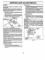
TO ADJUST
BRAKE (See Fig. 21)
CLUTCHINq
IDLER
Your tractor is equipped with an adjustable brake system
which is mounted on the right side of the transaxle.
If tractor requires more than six (6) feet stopping distance
at highspeed in highestgear, then brake must be adjusted.
•
IDLER
Depress clutch/brake pedal and engage parking brake.
Measure distance between brake operating arm and
nut "A" on brake rod.
4
If distance is other than 1-1/2", disengage parking
brake, loosen jam nut and turn nut "A" until distance
becomes 1-1/2". Retighten jam nut against nut =A".
TRANSAXLI
PULLEY
Engage parking brake and recheck distance.
Road test tractor for proper stopping distance as stated
above. Readjust if necessary. If stopping distance is
still greater than six (6) feet in highest gear further
maintenance is necessary. Contact your nearest authorized service center/department.
FIG. 22
20
SERVICE
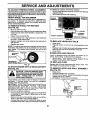
TO ADJUST
STEERING
AND ADJUSTMENTS
TO REMOVE CABLES, REVERSE ORDER
WHEEL ALIGNMENT
If steering wheel crossbars ere not horizontal (left to right)
when wheels are positionedstraightforward, remove steeringwheel and reassemble per instructionsinthe Assembly
section of this manual.
•
•
FRONT WHEEL TOE-IN/CAMBER
BLACK cable first from chassis and then from the fully
charged battery.
RED cable last from both battedes.
POSITIVE
.NEGATIVE
The front wheel toe-in and camber are not adjustable on
your tractor. If damage has occurred to affect the front
wheel toe-in or camber, contact your nearest authorized
service center/department.
TO REMOVE WHEEL
(See Fig. 23)
•
•
•
•
•
•
FOR REPAIRS
Block up axle securely.
Remove axle cover, retaining ring and washers toallow
wheel removal (rear wheel contains a square key - Do
not lose).
Repair tire and reassemble.
On rear wheels only: align grooves in rear wheel hub
and axle. Insert square key.
Replace washers and snap retaining ring securely in
axle groove.
Replace axle cover.
INAL
FIG. 24
TO REPLACE
HEADLIGHT
BULB
•
Raise hood.
•
Pull bulb holder out of the hole in the backside of the
grill.
•
Replace bulb in holder and push bulb holder securely
back into the hole in the backside of the gdll.
•
Close hood.
NOTE: To seal tire punctures and prevent flat tires due to
slow leaks, tire sealant may be purchased from your local
parts dealer. Tire sealant also prevents tire dry rot and
corrosion.
RETAINING
INTERLOCKS
WASHERS
AND RELAYS
Loose or damaged widng may cause your tractor to run
poorly, stop running, or prevent it from starting.
•
Check wiring. See electrical wiring diagram in the
Repair Parts section of this manual.
TO REPLACE
FIG. 23
Replace with 30 amp automotive-type plug-in fuse. The
fuse holder is located behind the dash.
TO START ENGINE WITH A WEAK BA'rrERY
(See Fig. 24)
I&
FUSE
TO REMOVE HOOD AND GRILL ASSEMBLY
(See Fig. 25)
•
•
•
ate explosive gases. Keep sparks, flame
and smoking materials away from batCAUTION:Always
teries.
Lead-acid
wear batteries
eye protection
generwhen around batteries.
If your battery is too weak to start the engine, it should be
recharged. If "jumper cables" are used for emergency
starting, follow this procedure:
IMPORTANT: YOUR TRACTOR IS EQUIPPED WITH A 12
VOLT NEGATIVE GROUNDED SYSTEM. THE OTHER
VEHICLE MUST ALSO BE A 12 VOLT NEGATIVE
GROUNDED SYSTEM. DO NOT USE YOUR TRACTOR
BATTERY TO START OTHER VEHICLES.
TO ATTACH JUMPER CABLES
Connect each end of the RED cable to the POSITIVE
(+) terminal of each battery, taking care not to short
against chassis.
Connect one end of the BLACK cable to the NEGATIVE (-) terminal of fully charged battery.
•
Connect the other end of the BLACK cable to good
CHASSIS GROUND, away from fuel tank and battery.
Raise hood.
Unsnap headlight wire connector.
Stand infront oftractor. Grasp hood at sides, titttoward
engine and lift off of tractor.
To replace, reverse above procedure.
HOOD
.
FIG. 25
21
HEADLIGHT
WIRE
CONNECTOR
SERVICE AND ADJUSTMENTS
FINAL SETTING
ENGINE
,
TO
ADJUST
THRO'I-rLE
CONTROL
(See Fig. 26)
The throttle control has been preset at the factory and
adjustment shouldnot be necessary. Check adjustment as
described below before loosening cable. If adjustment is
necessary, proceed as follows:
•
With engine not running, move throttle control lever
from slow to choke position. Slowly move lever from
choke to fast position.
Checkthatholes"A " ingovemorcontrolleverandhole
in governor plate line-up. If holes =A"are not aligned,
loosen clamp screw and move throttlecable until holes
are aligned. Tighten clamp screw securely.
GOVERNOR
CONTROL PLATE
GOVERNOR
CONTROL LEVER
HOLES "A"
CLAMP
SCREW
THROTTLE
CABLE
•
•
ACCELER,_TION TEST
•
Move throttle controllever from slow to fast position. If
engine hesitates er dies, turn idle mixture valve out
(counterclockwise) 1/8 turn. Repeat test and continue
to adjust, if necessary, until engine accelerates
smoothly.
High speed stop is factory adjusted. Do not adjust damage may result.
IMPORTANT:
NEVER TAMPER WITH THE ENGINE
GOVERNOR, WHICH IS FACTORY SET FOR PROPER
ENGINE SPEED. OVERSPEEDING THE ENGINE ABOVE
THE FACTORY HIGH SPEED SETTING CAN BE
DANGEROUS. IF YOU THINK THE ENGINE-GOVERNED
HIGH SPEED NEEDS ADJUSTING, CONTACT YOUR
NEAREST
AUTHORIZED
SERVICE
CENTER/
DEPARTMENT, WHICH HAS PROPER EQUIPMENT AND
EXPERIENCE
TO
MAKE
ANY
NECESSARY
ADJUSTMENTS.
FIG. 26)
TO ADJUST
CARBURETOR
Start engine and allow to warm for five minutes. Make
final adjusttnents with engine running and shift/motion
control lever in neutral (N) position.
Move throttlecontrol lever to slow position.With finger,
rotate and hold throttle lever against idle speed screw.
Turn idle speed screw to attain 1750 RPM.
While still holding throttle lever against idle speed
screw, turn idle mixture valve full travel clockwisethen
counterclockwise until engine runs rough. Turn valve
to a point midway between those two positions. Release throttle lever.
CABLE
IDLE SPEED
TN.OTTLE
(See Fig. 27)
LEVER
NOTE: The carburetor on this engine is low emission. It is
equipped with an idle fuel adjusting needle with a limiter
cap, which allows some adjustment within the limits allowed by the cap. Do not attempt to remove the limitercap.
The limiter cap cannot be removed without breaking the
adjusting needle.
The carburetor has been preset at the factory and adjustment should not be necessary. However, minor adjustment may be required to compensate for differences in fuel,
temperature, altitude or load. If the carburetor does need
adjustment, proceed as follows:
In general, turning idle mixture valve in (clockwise) decreases the supply of fuel to the engine givinga leaner fuel/
air mixture. Turning the idle mixture valve out (counterclockwise) increases the supply of fuel to the engine giving
a richer fuel/air mixture.
IMPORTANT: DAMAGE TO THE NEEDLE VALVE AND
THE SEAT IN CARBURETOR MAY RESULT IF SCREW IS
TURNED IN TOO TIGHT.
PRELIMINARY SETTING
•
Aircleaner assembly mustbe assembled tothe carburetor when making carburetor adjustments.
Be sure the throttle control cable is adjusted properly
(see above).
i
UMgE_
FIG. 27
22
STORAGE
ENGINE
Immediately prepare your tractor for storage at the end of
the season or if the tractor will not be used for 30 days or
more.
FUELSYSTEM
IMPORTANT:
IT IS IMPORTANT TO PREVENT GUM
DEPOSITS
FROM FORMING
IN ESSENTIAL
FUEL
SYSTEM PARTS SUCH AS CARBURETOR, FUEL FILTER,
FUEL HOSE, OR TANK DURING STORAGE.
ALSO,
EXPERIENCE
INDICATES THAT ALCOHOL BLENDED
FUELS (CALLED GASOHOL OR USING ETHANOL OR
METHANOL) CAN ATTRACT MOISTURE WHICH LEADS
TO SEPARATION AND FORMATION OF ACIDS DURING
STORAGE.
ACIDIC GAS CAN DAMAGE THE FUEL
SYSTEMOF
AN ENGINE WHILE IN STORAGE.
•
Drain the fuel tank.
gasoline in the tank inside a building
where
fumes
may store
reachthe
an tractor
open flame
CAUTION:
Never
with
or spark. Allow the engine to cool
before storing in any enclosure.
TRACTOR
Remove mower from tractor for winter storage. When
mower is to be stored for a period of time, clean it thoroughly, remove all dirt, grease, leaves, etc. Store in a
clean, dry area.
•
Cleanentiratractor(See"CLEANING"intheCustomer
Responsibilities section of this manual).
•
Inspect and replace belts, if necessary (See belt replacement instructionsin the Service and Adjustments
section of this manual),
•
Lubricate as shown in the Customer Responsibilities
section of this manual.
•
Be sure that all nuts, bolts and screws are securely
fastened. Inspect moving parts for damage, breakage
and wear. Replace if necessary.
•
Touch up all rusted or chipped paint surfaces; sand
lightlybefore painting.
•
Start the engine and let it run until the fuel lines and
carburetor are empty.
•
Never use engine or carburetor cleaner products in the
fuel tank-or permanent damage may occur.
Use fresh fuel next season.
•
NOTE: Fuel stabilizer is an acceptable alternative in
minimizing the formation of fuel gum deposits during storage. Add stabilizer to gasoline in fuel tank or storage
container. Always follow the mix ratio found on stabilizer
container. Run engine at least 10 minutes after adding
stabilizer to allow the stabilizer to reach the carburetor. Do
not drain the gas tank and carburetor ifusing fuel stabilizer.
ENGINE OIL
Drain oil (with engine warm) and replace with clean engine
oil. (See "ENGINE" in the Customer Responsibilities
section of this manual).
BA'I-rERY
Fully charge the battery for storage.
After a period of time in storage, battery may require
recharging.
CYLINDER(S)
•
Remove spark plug(s).
To help prevent corrosion and power leakage during
long periods of storage, battery cables should be
disconnected and battery cleaned thoroughly(see"TO
CLEAN BATTERY AND TERMINALS in the Customer Responsibilities section of this manual).
•
Pour one ounce of oil through spark plug hete(s) into
cylinder(s).
•
Turn ignition keyto"START" positionfor a few seconds
to distribute oil.
After cleaning, leave cables disconnected and place
cables where they cannot come in contact with battery
terminals.
•
Replace with new spark plug(s).
If battery is removed from tractor for storage, do not
store battery directly on concrete or damp surfaces.
•
OTHER
Do not store gasoline from one season to another.
•
'Replace your gasoline can if your can starts to rust.
Rust and/or dirt in your gasoline will cause problems.
•
If.possible, store your tractor indoors and cover it to
g,ve protection from dust and dirt.
•
Cover your tractor with a suitable protective cover that
does not retain moisture. Do not use plastic. Plastic
cannot breathe which allows condensation to form and
will cause your tractor to rust.
IMPORTANT: NEVERCOVERTRACTORWHILE ENGINE
AND EXHAUST AREAS ARE STILL WARM.
23
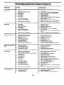
TROUBLESHOOTING
PROBLEM
Will not start
CAUSE
CORRECTION
1.
Out of fuel.
t.
Fill fuel tank.
2.
3.
4.
5.
6.
7.
Engine not =CHOKED" properly.
Engine flooded.
Bad spark plug.
Dirty air filter.
Dirty fuel filter.
Water in fuel.
2.
3.
4.
5.
6.
7.
8.
9.
Loose or damaged widng.
Carburetor out of adjustment.
8.
9.,
See "TO START ENGINE" in Operation sect_n.
Wait several minutes before attempting to start.
Replace spark plug.
Clean/replaca air filter.
Replace fuel filter.
Drain fuel tank and carburetor, refill tank with fresh
gasoline and replace fuel tilter.
Check all widng.
See "To Adjust Carburetor" in Service Adjustments
secfion.
10.
Hard to start
POINTS
Engine valves out of adjustment.
10.
Contact an authorized service cantar/departmant.
1.
2.
3.
4.
5.
6.
7.
Dirty air filter.
Bad spark plug.
Weak or dead battery.
Dirty fuel filter.
Stale or dirty fuel.
Loose or damaged widng.
Carburetor out of adjustment.
t.
2.
3.
4.
5.
6.
7.
Clean/replace air filter.
Replace spark plug.
Recharge or replace battery.
Replace fuel filter.
Drain fuel tank and refill with fresh gasoline.
Check all widng.
See "To Adjust Carburetor" in Service Adjustments
section.
8.
Engine valves out of adjustment.
8.
Contact an authorized service center/department.
I.
2.
3.
4.
5.
6.
7.
8.
9.
Clutchrbrake pedal not depressed.
Attachment clutch is engaged.
Weak or dead battery.
Blown fuse.
Corroded battery terminals.
Loose or damaged widng.
Faulty ignition switch.
Faulty solenoid or starter.
Faulty operator presence switch(es).
1.
2.
3.
4.
5.
6.
7.
8.
Depress clutch/brake pedal.
Disengage attachment clutch.
Recharge or replace battery.
Reptace fuse.
Clean battery terminals.
Check all wiring.
Check/replaca ignition switch.
Check/replace solenoid or starter.
9.
Contact an authorized service canter/departmant.
Engine clicks but will not
start
1.
2.
3.
4.
Weak or dead battery.
Corroded battery terminals.
Loose or damaged widng.
Faulty solenoid or starter.
1.
2.
3.
4.
Recharge or replace battery.
Clean battery terminals.
Check all wiring.
Check/replace solenoid or starter.
Loss of power
1.
2.
3.
4.
5.
6.
7.
8.
9.
(_ut_ng too much grass/too fast.
Throttle in "CHOKE" position.
Build-up of grass, leaves and trash under mower.
Dirty air filter.
Low oil level/dirty oil.
Faulty spark plug.
Dirty fuel filter.
Stale or dirty fueL
Water in fuel.
1.
2.
3.
4.
5.
6.
7.
8.
9.
Set in =Higher Cut" position/reduce speed.
Adjust throttle control.
Clean underside of mower housing.
Clean/replace air filter.
Check oil level/change oil.
Clean and rsgap or change spark plug.
Replace fuel filter.
Drain fuel tank and refill with fresh gasoline.
Drain fuel tank and carburetor, refill tank with fresh
gasoline and replace fuel filter.
Connect and tighten spark plug wire.
Clean .ngine air screenffins.
Clean/replace muffler.
Check all wiring.
See "To Adjust Carburetor" in Service Adjustments
s_cfion.
Engine will not turn over
Excessive vibration
10.
11.
12.
13.
14.
Spark plug wire loose.
Dirty engine air screen/fins.
Dirty/clogged muffler.
Loose or damaged widng.
Carburetor out of adjustment.
t0.
11.
12.
13.
14.
15.
Engine valves out of adjustment.
15.
Contact an authodzed service canter/department.
1.
2.
3.
Replace blade. Tighten blade bolt.
Replace blade mandrel.
Tighten loose part(s). Replace damaged parts.
1.
2.
Worn, bent or loose blade.
Bent blade mandrel.
3.
Loose/damaged part(s).
24
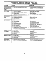
TROUBLESHOOTING
PROBLEM
CAUSE
POINTS
CORRECTION
Engine continues to run
when operator leaves seat
with attachment clutch
engaged
1.
Faulty operator-safety presence control system.
1.
Check wiring, switches and connections. If not
corrected, contact an authorized service center/
department.
Poor cut - uneven
1.
2.
Wom, bent or loose blade.
Mower deck not level.
1.
2.
Replace blade. Tighten blade bolt.
Level mower deck.
3.
4.
Buildup of grass, leaves, and trash under mower.
Bent blade mandrel
5.
Clogged mower deck vent holes from buildup of
grass, leaves, and trash around mandrels.
Mower blades will not
rotate
1.
2.
3.
4.
Obstruction in clutch mechanism.
Worn/damaged mower drive belt.
Frozen idler pulley.
Frozen blade mandrel.
Poor grass discharge
1.
2.
3.
4.
Engine speed too slow.
Travel speed too fast.
Wet grass.
Mower deck not level.
5.
6.
7.
8.
9.
10.
1t.
3.
4.
• 5.
Clean underside of mower housing.
Replace blade mandrel.
Clean around mandrels to open vent holes.
1. Remove
2. Replace
3..Replace
4. Replace
Low/uneven tire air pressure.
Worn, bent or loose blade.
Buildup of grass, leaves and trash under mower.
Mower drive belt worn.
Blades improperly installed.
Improper blades used.
Clogged mower deck vent holes from buildup of
grass, leaves, and trash around mandrels.
1.
2.
3.
4.
5.
6.
7.
8.
9.
10.
11.
obstruction.
mower drive belt.
idler palley.
blade mandrel.
Place throttle control in "FAST" position.
Shift to slower speed.
Allow grass to dry before mowing.
Level mower deck.
Check tires for proper air pressure.
Replace/sharpen blade. Tighten blade bolt.
Clean underside of mower housing.
Replace mower drive belt.
Reinstall blades sharp edge down.
Replace with blades _isted in this manual.
Clean around mandrels to open vent holes.
Headlight{a) not working
(if so equipped)
1.
2.
3.
4.
5.
Switch is=OFF".
Bulb(s) burned out.
Faulty light switch.
Loose or damaged wiring.
Blown fuse.
1.
2.
3.
4.
5.
Turn switch =ON".
Replace bulb(s).
Check/replace light switch.
Check wiring and connections.
Replace fuse.
Battery will not charge
1.
2.
Bad battery cell(s).
Poor cable connections.
3.
4.
Faulty regulator (if so equipped).
Faulty alternator.
1.
2.
3.
4.
Replace battery.
Check/clean all connections.
Replace regulator.
Replace alternator.
1.
Engine throttle control not sat at "SLOW"
position for 30 seconds before stopping engine.
1.
Move throttle control to "SLOW" position and allow
to idle for 30 seconds before stopping engine.
Engine "backfires"
when turning engine
"OFF"
25
SERVICE NOTES
26
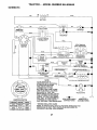
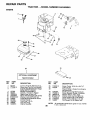
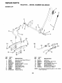
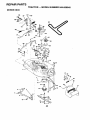
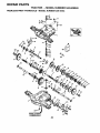
TRACTOR - - MODEL NUMBER 944.609040
SCHEMATIC
BATTERY
.ED
FUSE 30 AMP.
RED
STARTER
;---_---,
)
WHITE
I
' C_:q
,
:
I O 'NO D
I
t .......
iG
BIJ_K
'©
I
J
CLUTCH / BRAKE
(PEDAL UP)
A1
L
WHITE
SEAT SWITCH
(NOT OCCUPIED)
IGNITION
SWITCH
WHIT E
I.......
I
I
I
I
I
BIJ_CK
I
'
©
O
II
BLACK
BLACK
BL_CK (CLUTCH OFF)
"_[
GROUNDING
CONNECTOR
]
METER
HOUR
(OPTIONAL)
•
, _UEL
I_
i
_
' 8LACK (_
_UNEi
I_
IGNITION
UNIT
I
SPARK
LJ PLUG
GAP
I
(2 PLUGS ON
i
TWIN CYL. ENGINES)
3 AMP OC O 3600 RPM
CHARGING SYSTEM OUTPUT
I__
FUEL SHUT-OFI_
RED
SOLENOID
O_--E--
(CHARGING SYSTEM DISCONNECTED)
28 VOLTS AC MEN @ 3600 RPM
"_
I_/1
_
__,
[
UGMi"_'NG
SY:_MR_MUTF,_
_
DIODE
.... NOTE '
I
;ALTERNATOR
\ ...............
14 VOLTS AC MIN. @ 3600 RPM (UGHTS OFF)
i
M m,.,.---
IGNITION
B
,
SWITCH
PosmoN
CIRCUIT
"MAKE"
OFF
RUN/LIGHT
M+G+A1
B+A1
NONE
A2+L
RUN
B+A1
NONE
START
B + S + A1
NONE
YOUR TRACTOR IS
I
EQUIPPED WITH A SPECIAL
ALTERNATOR SYSTEM.
,
THE LIGHTS ARE NOT
CONNECTED TO THE
BATI'ERY, BUT HAVE THEIR
OWN ELECTRICAL SOURCE.
BECAUSE OF THIS, THE
BRIGHTNESS OF THE LIGHTS
WILL CHANGE WITH ENGINE
SPEED. AT IDLE THE LIGHTS
WILL DIM. AS THE ENGINE IS
SPEEDED UP, THE LIGHTS
WILL BECOME THEIR BRIGHTEST.
WIRING INSULATED
B_OWN (j_l_
(_
HEADLIGHTS
•
©
NON-REMOVABLE
CONNECTIONS
REMOVABLE
CONNECTIONS
CLIPS
NOTE: IF WIRING INSULATED CLIPS WERE REMOVED FOR
SERVICING OF UNIT. THEY SHOULD BE REPLACED TO
PROPERLY SECURE YOUR WIRING.
27
II
REPAIR PARTS
TRACTOR - - MODEL NUMBER 944,609040
ELECTRICAL
I
I
41
7O
I
25
I
"16
29
28
28
REPAIR PARTS
TRACTOR - - MODEL NUMBER 944.609040
ELECTRICAL
KEY
NO.
PART
NO.
1
2
8
16
19
20
21
22
24
25
26
27
28
29
30
33
4O
41
42
43
44
45
52
70
144925
74760412
156417
153664
STD551125
73350400
166181
4152J
4799J
146147
166180
73510400
4207J
121305X
163968
140403
166151
71110408
131563
145673
73640400
121433X
141940
166659
NOTE:
DESCRIPTION
Battery 12 Volt 25 Amp
Bolt Hex Hd 1/4-20unc X 3/4
Case Battery
Switch Interlock Push -In
Washer Lock 1/4 .
Nut Jam Hex 1/4-20 Unc
Harness Asm Light W/4152J
Bulb Light #1156
Cable Battery 6 Ga 11"red
Cable Battery 6 Ga w/16 wire,red
Fuse 15 AM P
•
Nut Keps Hex 1/4-20 Unc
Cable Ground 6 Ga 12" black
Switch Plunger Nc Gray
Switch Ign Delta Push-In
Key Ign
Harness Ign
Bolt BIk Fin Hex 1/4-20 X 1/2
Cover Terminal Red
Solenoid
Nut Keps BIk Hex 1/4-20 unc
Ammeter Rectangular 6 Amp
Protection Wire Loop
Harness Eng B&S
All component dimensions give in U.S. inches
1 inch = 25.4 mm.
29
REPAIR PARTS
TRACTOR
CHASSIS
- - MODEL NUMBER 944.609040
AND ENCLOSURES
3O
17
21
22
5
18
26
26
25
161
I
29
14
28
26
33
10
26
14
30
REPAIR PARTS
TRACTOR
CHASSIS
- - MODEL
NUMBER
944.609040
AND ENCLOSURES
KEY PART
NO, NO.
DESCRIPTION
1
2
3
4
5
6
7
8
9
10
11
13
14
15
16
17
18
19
21
22
24
25
26
28
29
30
31
33
34
35
37
38
39
54
140
145
161
--
Chassis
Drawbar Stretch
Screw Thdrol 3/8-16 x 3/4 Ty-tt
Washer 13/32 x 3/4 x 16 Ga.
Bumper Hood/Dash
Saddle
Shield, Heat, Hood
Clip Retainer Slide-On
Dash Silkscreened
Bolt Carriage 3/8-16 x 1
Panel Dash Lh
Panel Dash Rh Slkscr
Screw Thdrol 3/8-16 x 1/2 Ty-tt
Screw Mach Trhd 5/16-18 unc x 3/4
Nut Keps 5/16-18
Hood Asm Pnt Weld Slpe
Bumper Hood
Screw
Rivet Ratchet Nylon
Washer Nylon BIk 28 x 75 x 19
Bolt Fin Hex 3/8-16 x 1 Gr. 5
Washer 13/32 x 13/16 x 12 Ga
Nut Lock Hex w/Ins 3/8-16
Grille Black
Lens Headlight Bar Clear
Fender Pnt
Bracket Pnt Fender
Footrest Pnt Lh
Footrest Pnt Rh
Bolt Carriage 3/8-16 x 3/4
Screw Thdrol 5/16-18 x 1/2
Bracket Asm. Pivot LH
Bracket Asm, Pivot RH
Screw Hex Wshd 8-18 x 7/8
Bracket Suspension Front
Rod Pivot Ohassis/Hood
ExtrusionHood
Plug Button Black
165480
140356
17490612
STD551025
155272
155924X012
126842X
155138
166322X010
STD533710
155927
155934X010
17490608
74180512
STD541431
154989X558
126938X
17411310
122933X
124479X
STD523710
19131312
STD541437
140135X428
124029X599
166884X558
136619
145244X558
145243X558
STD533707
17490508
139886
139887
161464
158418
156524
161547
5479J
NOTE: All component dimensions given in U.S. inches
1 inch = 25.4 mm
31
REPAIR PARTS
TRACTOR - - MODEL NUMBER 944.609040
DRIVE
32
REPAIR PARTS
TRACTOR
- - MODEL NUMBER 944.609040
DRtVE
KEY
NO.
1
2
3
4
5
6
7
8
10
11
12
13
14
18
19
21
22
24
25
26
27
28
29
30
31
32
34
35
36
37
38
39
40
41
PART
NO.
......
146682
123666X
12000028
121520X
17490512
162240
131679
STD561210
105701X
19151216
74550412
STD551125
STD523710
STD541437
106933X
130804
STD541237
106888X
STD551037
STD561210
145204
124236X
130807
127275X
STD523107
155071
120183X
STD551062
STD571810
131494
STD523727
4470J
165838
DESCRIPTION
Transaxle (See Breakdown)
Peerless Model 206-545C
Spring Extension Brake
PulleyTransaxle 18" tires
RingFletainer # 5100-62
Strap Torque Rh Pnt BIk
Screw Thdrol 5/16-16 X 3/4 Tyt
Plate Pnt Rod Shift T/a (blk)
Rod Shifter Black(dana)
Pin Cotter 1/8 x 1
Washer Plate Shf 388 Sq Hole
Washer 15/32 X 3/4 X 16ga
Bolt 1/4-28 UNF Gr. 8 W/Patch
Washer LockHw Helical 1/4
Bolt Fin Hex 3/8-16 UNC x 1 Gr. 5
Nut Lock Hex 3/8-16
Knob Rd 1/2-13 Plstc Thds BIk
Rod Brake Lt
Nut Hex Jam 3/8-16
Spring Rod Brake 2 00 Zinc '
Washer 13/32 x 13/16 x 16 Ga.
Pin Cotter 1/8
Rod Brake Parking Lt/Yt
Cap Parking Brake Red
Bracket Transmission
Keeper Belt Lh Lt 14 Ga
Bolt Hex Hd.5/16-18 x 3/4
Shaft Asm Pedal Foot
Bearing Nylon BIk 6291d
Washer 21/32 x 1 x 16 Ga.
Roll Pin 3/16 x 1"
PulleyIdler
Flat
Bolt Fin hex 3/8-16 x 2 3/4
Spacer Split 395X 59Bzp
Keeper Belt Idler
KEY
NO.
PART
NO.
DESCRIPTtON
42 19131312
Washer 13132 X 13/16 X 12 Ga
47 127783
Pulley Idler V Groove Plastic
48 154407
Bellcrank Clutch Grnd Dry Stl
49 123205X
Retainer Belt Style Spring
50 STD523715
Bolt Hex Hd 3/8-16 x 1 1/2
51 STD541437
Nut Crown Lock3/8-16
52 ST1;)541431 Nut Crown Lock 5/16-18
53 105710X
Link Clutch 7 66
55 105709X
Spring Return Clutch 6 75
56 STD523712 • Bolt Fin Hex 3/8-16 x 1 1/4
57 130801
V-belt Ground Drive 95 30
58 127274X
Keeper Belt Rh Lt PnVzinc 16g
59 140312.
Keeper Belt Chassis Span Ctr.
61 17490612
Screw Thdrol 3/8-16x3/4 Ty-tt
62 8883R
Cover Pedal BIk Round
63 140186
Pulley Engine
64 71170764
Bolt, Hex 7/16-20 x 4 Grade 5
65 STD551143
Washer, Lock, Hvy Hlcl Spring 7/16
66 154778
Keeper Belt Engine FIproof
70 134683
Guide Belt Dr Mower Rh
72 19132012
Washer 13/3_. X 1-1/4 X 12 Ga
74 137057
SpacerAxle
75 121749X
Washer 25/32 X 1 1/4 X 16 Ga
76 STD581075
E Ring
77 123583X
Key Square 2 0 X 1845/1865
78 121748X
Washer 25/32 X 1 5/8 X 16ga
79 2228M
Key, Woodruff #9 3/16 x 3/4
96 4497H
Retainer Spring
112 19091210
Washer9/32X3/4X10Ga
113 127285X
Strap Torque LH
116 72110610
Bolt, Rdhd Sqnk 3/8-16 x 1.25
145 74490540
Bolt Hex Flghd 5/16-18 x Gr. 5
150 165850
Bushing Bellcrank
151 19133210
Washer13/32x2x10Ga.
NOTE: All component dimensions given in U.S. inches
1 inch = 25.4 mm
33
REPAIR PARTS
TRACTOR
STEERING
- - MODEL NUMBER 944.609040
ASSEMBLY
p
_41
62
67
47
I_ _
46
32
43
3O
34
REPAIR PARTS
TRACTOR
STEERING
- - MODEL NUMBER 944,609040
ASSEMBLY
KEY
NO.
PART
NO.
1
2
3
4
5
6
7
8
9
10
11
13
15
17
18
19
22
23
25
26
27
28
29
30
32
36
37
38
39
40
41
42
43
46
47
62
65
66
67
68
79
80
139768
154427
156483
157473
6266H
121748X
19272016
12000029
3366R
156438
STD551137
154779
73901000
156545
57079
160395
165857
165851
154406
126847X
136874
19131416
17490612
STD561210
130465
155099
152927
139769
19133808
STD541537
104820X
124417X
121749X
121232X
6855M
167903
154780
154404
74781044
154429
19132012
74950612
DESCRIPTION
Wheel Steering Auto Black
Axle Asm Front
Spindle Asm Lh
Spindle Asm Rh
Bearing Race Thrust Harden
Washer 25/32 X 1 5/8 X 16ga
Washer 27/32 X 1 1/4 X 16 Ga
Ring Klip #t5304-75
Bearing Col Strg BIk
Link Drag Extended
Lockwasher Spr. 3/8 •
Spacer Bearing Axle Front
Locknut Flange 5/8-11 Unc
Shaft Asm Strg 5/8 X 15 19 Lt
Washer Thrust 515x 750x 033
Support Shaft
Screw hex Wsh Hd Torx
Shaft Asm Pittman
Bracket Steering
Bushing Rod Tie BIk Lt
Gear Sector
Washer 13/32 X 7/8 X 16ga
Screw Thdrol 3/8-16x3/4 Ty-tt
Pin Cotter
Rod Tie Wire Form 19 75 Mech
Bushing Strg 5/8 Id Dash
Screw TI #10-32 x 5 x 3/8 Flange
Insert Cap Strg
Washer 13/32 X 2-3/8 X 8 Ga
Locknut Center 3/4-24
Adaptor Wheel Strg 640/635id
Boot Shaft Steering
Washer 25/32 X 1 1/4 X 16 Ga
Cap Spindle Fr Top BIk
Fitting Grease
Kit Steering Assembly Service
Spacer Axle
Bearing Arm Pittman
Bolt Fin Hex 5/8-11 UNC x 2-3/4
Brace Axle
Washer 13/3°2x 1 1/4 x 12 Ga
Bolt Hex Nylon 3/8-16 x 3/4
NOTE: Allcomponentdimensions
1 inch = 25.4mm
35
givenin U.S. inches
REPAIR PARTS
TRACTOR
- - MODEL NUMBER 944.609040
SEAT ASSEMBLY
5
21
5
25
12
KEY
NO.
PART
NO.
1
2
3
4
5
6
7
8
9
10
11
12
140122
140551
STD523710
19131610
145006
STD541437
124181X
17490616
19131614
155925
166369
121246X
DESCRIPTION
Seat
Bracket Pnt Pivot Seat (blk)
Bolt Fin Hex 3/8-16 x 1
Washer 13/32 X 1 X 10 Ga
Clip Push-In Hinged
Nut Lock Hex 3/8-16
Spring Seat Cprsn 2 250 BIk Zi
Screw Thdrol 3/8-16 X 1 Ty-tt
Washer 13/32 X 1 X 14 Ga
Pan Pnt Seat (blk)
Knob Seat Adj Wingnut
Bracket Pnt Mounting Switch
KEY
NO.
PART
NO.
13
14
15
16
17
21
22
24
25
121248X
72050412
134300
121250×
123976X
153236
STD541431
19171912
127018X
DESCRIPTION
Bushing Snap BIk Nyl 50 Id
Bolt Rdhd Sht Nk 1/4-20x1-1/2
Spacer Split 28 X96 Yel Zinc
Spring Cprsn 1 27 Blk Pnt
Nut Lock 1/4 Lge Fig Gr 5 Zinc
Bolt Shoulder 5/16-18 Unc Blkz-2A
Nut Lock 5/16-18
Washer 17/32 X 1-3/16 X 12 Ga
Bolt Shoulder 5/16-18 X 62
NOTE: All component dimensions given in U.S. inches
1 inch = 25.4 mm
36
REPAIR PARTS
TRACTOR - - MODEL NUMBER 944.609040
DECALS
13
3
9
9
9
13
10
16
15
12
14
11
KEY
NO.
1
3
9
10
11
12
13
14
PART
NO.
157163
169313
163204
157140
101892X
146046
163249
160396
WHEELS
2_
DESCRIPTION
KEY
NO,
Decal
Decal
Decal
Decal
Decal
Decal
Decal
Decal
15
16
17
20
-----
Oper Sdl P/L Gear Dr E/F
Relacement Parts
Craftsman
Caution English/French
Clutch/brake English]French.
V-belt Dr Sch Tractor E
Panel Dash
V-belt Schematic 42"eng
& TIRES
5,8
4,10
7
11
PART
NO.
137259
149517
133179
273511
157199
138311
168506
168507
KEY
Nd.
PART
NO.
1
2
3
4
5
6
7
8
9
10
11
--
59192
65139
106222X
59904
106732X427
278H
9040H
106108X427
106268X
7152J
104757X
144334
DESCRIPTION
Decal Warning Multi-Language
Decal Battery Danger/Poison
Decal Mower QC
Decal HP Engine
Pad Footrest Generic Sq
Decal Lift Handle
Manual Owners English
Manual Owners French
DESCRIPTION
Cap Valve Tire
Stem Valve
Tire F Ts 15 X 6 0 - 6 Service
Tube Front (Service Item Only)
Rim Asm 6"front White Service
FittingGrease (Front Wheel Only)
Bearing Flange (Front Wheel Only)
Rim Asm 8"rear White Service
Tire R Ts 18x9.5-8 C Service
Tube Rear (Service Item Only)
Cap Axle BIk 1 50 X 1 00
Sealant, Tire (10 oz. Tube)
NOTE: All component dimensions given in U.S. inches
1 inch = 25.4 mm
37
REPAIR PARTS
TRACTOR - - MODEL NUMBER 944.609040
ENGINE
72
62
81
13
4
1;
38
78
33
23
29
/
\
OPTIONAL
EQUIPMENT
Spark Arrester
KEY
NO.
PART
NO.
1
2
3
162144
17720410
4
13
14
15
16
23
29
31
32
33
137352
165291
13280324
13200300
STD551237
159880
137180
109202X
158990
123487X
DESCRIPTION
Control Throt Rh BIk Pd115 10
Screw Hex Thd Cut 1/4-20x5/8 T
Engine (See Breakdown) Bdggs
Model 287707-1255-E1
Muffler Exhaust B&s Lt
Gasket 1 313 Id Tin Plated
Nipple Pipe 3/8 Npt X 3"
Elbow Std 90 Degree 3/8-18 Npt
Washer Lock Ext Tooth 3/8
Shield Browning/Debris Guard
Arrestor Spark
Tank Fuel 1 25 Fr
Cap Asm Fuel
Clamp Hose BIk
KEY
NO.
PART
NO.
35
37
38
17490512
137040
---
40
44
46
62
72
78
81
124028X
17490412
19091416
STD551131
71070512
17490620
128861
NOTE:
38
DESCRIPTION
Screw Thdrol 5/16-18 x 3/4 TyT
Line Fuel 20"
Plug Oil Drain (Order From Engine
Manufacturer)
Bushing Snap Nyl BIk Fuel Line
Screw Hexwsh Thdrol 1/4-20x3/4
Washer 9/32 X 7/8 X 16ga
Washer Lock Hvy Hlcl Spr 5/16
Screw Hexhd Cap 5/16-18x3/4
Screw Thdrol 3/8-16x1-1/4 Tytt
Nut Flange 1/4-20 Starter Nut
All component dimensions given in U.S. inches
1 inch = 25.4 mm
REPAIR PARTS
TRACTOR - - MODEL NUMBER 944.609040
MOWER
LIFT
7
8
/ /
! i
,I
5
I
/
I.
/
,/'
3
13
2
4
6
6
11_
_12
13
19
20
15
32
/_
1718
20
20
/
KEY
NO.
PART
NO.
1
2
3
4
5
6
7
8
11
12
13
159460
159474
105767X
STD581062
19211621
120183X
125631X
122365X
139865
139866
STD624008
KEY
NO.
DESCRIPTION
15
16
17
18
19
20
31
32
Wire Asm Inner/Sprg W/Plngr LT
Shaft Asm Lift
Pin Groove
E Ring #5133-62
Washer 21/32 x 1 x 21 Ga.
Bearing Nylon
Grip Handle Fluted
Button Plunger Red
Link Lift Lh
Link Lift Rh
Retainer Spring
PART
NO.
127218
73350800
130171
73680800
139868
163552
140302
73540600
NOTE:
39
DESCRIPTION
Link Front
Nut Jam Hex 1/2-13 Unc
Trunnion BIk Zinc
Nut, Crownlock 1/2-13 Unc
Arm Suspension Rear
Retainer Spring
Bearing Pvt Lift Spherical
Nut Crownlock 3/8-24
All component dimensions given in U.S. inches
1 inch = 25.4 mm
REPAIR PARTS
TRACTOR
MOWER
- - MODEL NUMBER 944.609040
DECK
76
77
73
.78
79 83
45
34
.33
31
_21
>21
_3
!
24
\
2
16
28
29
40
27
REPAIR PARTS
TRACTOR - - MODEL NUMBER 944.609040
MOWER
DECK
KEY
NO.
PART
NO.
1
2
3
4
5
6
8
9
10
11
164961
STD533107
138017
138440
STD624008
130832
850857
STD551137
140296
134149
138498
.o
139775
138971
12
13
14
15
16
17
18
19
20
21
22
23
24
25
26
27
28
29
30
31
32
33
34
35
36
37
129895
137645
128774
110485X
140329
72110610
STD533106
132827
159770
STD541431
134753
131267
105304X
123713X
110452X
130968
19111016
131491
157722
129963
153535
137266
STD533717
133835
131494
STD551037
DESCRIPTION
Housing Assembly, 42"
Bolt 5/16-18 x314
Bracket Asm Fr. Sway Bar 3/42
Bracket Asm Deck 42" Sway Bar
Retainer Spring
Arm, Suspension, Rear
Bolt 3/8-24 x 25 Grade 8 patched
Washer, Lock3/8
Washer, Hardened
Blade, Mulching 42" Std (Originally
equiped with)
(Following Blades are Optional)
Blade Mower 42" Hi-Lift Std ( For
better bagging, especially in wet
conditions)
Blade Mulching Premium 42" (For
better wear when mulching)
Blade Mower 42" Hi-Lift Premium
(For better wear when bagging in
heavy or wet conditions)
Bearing, Ball #6204
Shaft Assembly, Mandrel, Vented
Housing, Mandrel, Vented
Bearing, Ball, Mandrel
Stripper, Vented Mower Deck
Bolt, Rdhd Sqnk 3/8-16 x 1-1/4
Bolt, Carriage 5/16-18 x 5/8
Bolt, Shoulder
Baffle, Vortex
Nut Crownlock 5/16-18
Stiffener Bracket
Bracket, Deflector Mower 42"
Cap, Sleeve 80 x 112 BIk Mower
Spring, Torsion, Deflector 2 52
Nut, Push Phos & Oil
Shield, Deflector 42" BIk
Washer 11/32 x 5/8 x 16 Gauge
Rod, Hinge 42" 6 75 WIG
Screw Thdrol Rolling Washer Head
Washer, Spacer Mower Vented
Pulley, Mandrel
Nut, Toplock 9/16
Bolt Rdhd 3/8-16 x 1 3/4
Fastener, Christmas Tree
Pulley, Idler, Flat
Washer 13/32 x 13/16 x 16 Gauge
KEY
NO,
PART
NO.
40
41
43
44
45
46
48
49
50
61
52
53
54
55
56
58
59
67
68
71
72
73
74
75
76
77
78
79
80
81
82
83
84
86
92
128
132
STD541437
133551
140083
14d088
STD624003
137729
133944
155066
131340_
STD541410
139888
131845
133943
155046
122052X
140086
141043
162113
144200
142427
131870
127847
121748X
12000029
128903
127845
160571
127498
153701
STD541237
142028
120958X
156084
72140620
STD541437
153390
19132203
141, 6266H
- - 130794
--
164963
DESCRIPTION
Nut Crownlock 3/8-16
Rod, Pivot, with Nibs
Rod, Clutch, Secondary, with Nibs
Guard, Mandrel, LH
Retainer Spring 1"
• Screw, Thdrol 1/4-20 x 5/8 T
Washer, Hardened
Roller Assembly, Cam Follower
Bolt, Shoulder #10-24 Grade 5
Locknut #10-24
Bolt, Shoulder 5/16-18 UNC
Arm Assembly, Pad, Brake
Washer, Hardened
Arm, Idler
Spacer, Retainer
Spring Torsion Brakes
Guard TUV Idler
Knob Custom Oval
V-Belt, 42" Mower
Rod, Clutch, Primary
Spring, Retainer
Arm, Clutch, Secondary
Washer 25/32 x 1-5/8 x 16 Gauge
Ring, Klip
Bolt, Shoulder 3/8-16 UNC x 1.44
Keeper, Spring
Arm, Clutch, Primary
Bushing, Large, Brass
Spring, Mower Clutch
Nut Hex Jam 3/8-16 UNC
Trunnion Adj
Washer, Sintered
Keeper, Belt, Idler
Bolt, Carriage 3/8-16 x 2-1/2
Nut, Lock Hex w/Ins 3/8-16 UNC
Washer, Felt
Spacer Washer 13/32 ID x 1-3/8
OD x 1/4
Washer Thrust .75 x 1.230
Mandrel Assembly (Includes Key
Numbers 8-10,12-15, 31 and 33)
Mower Deck, Complete
NOTE" All component dimensions given in U.S. inches
1 inch = 25.4 mm
41
REPAIR PARTS
TRACTOR - - MODEL NUMBER 944,609040
PEERLESS
PMST TRANSAXLE
- MODEL NUMBER
206-545C
35A2gB
156
8
70 6A
83
157
82
16
4
47
56
57
54
58
13
59
34
61
29
35
157
41A
79
NUMBERSI
42
_/
REPAIR PARTS
TRACTOR - - MODEL NUMBER 944.609040
PEERLESS
KEY PART
NO. NO.
1
2
3
4
5
6
6A
7
8
8A
9
10
11
12
13
14
15
17
18
20
21
22
25
25A
26
27
28
29
29A
29B
29C
30
31
772147
780086A
770128
776395
776409
778364
778369
778330
792180
792047
784352
784378
778334
778309
778368
778368
778370
786188
786102
792077A
792078
792079
792073A
792177
792125
792035
788040
780072
780160
780051
780199
780108
780001
31A
32
34
35
35A
36
37
38
39
40
780195
788083
780194
780193
780197
790075
790007
799021
786026
792076A
PMST TRANSAXLE
- MODEL NUMBER
206-545C
KEY PART
NO. NO.
DESCRIPTION
Transaxle Cover
Needle Bearing 5/8"
Transaxle Case
Countershaft
Output Shaft
Spur Gear (38 teeth)
Spur Gear (15teeth)
Spur Gear (11 teeth)
Shift Key
Woodruff Key #9
Shift Collar
Shift Rod & Fork
Bevel Gear (30 teeth)
Input Bevel Pinion (13 teeth)
Bevel Gear (13 teeth) (Include, 14)
Bevel Pinion (13 teeth) (Include, 13)
Ring Gear (43 teeth)
Drive Pin
Spacer 1.130 X.695
Ball 5/16 dia
Set Screw 3/8 - 16 x 3/8"
Spring .310 OD x .625 L
Screw 1/4- 20 x 1-1/4"
Screw 1/4-20 x 1-3/8"
Retaining Ring (pkg of 2)
Retaining Ring
Retaining Ring
Thrust Washer .627 ID x .031W
Thrust Washer .762 ID x .031W
Thrust Washer.762 ID x .031W
Anti-Rotation Washer .632
Cup Washer 1.127 ID x .032W
Flat Washer .750 ID x .056W (Use
As Needed)
Flat Washer.750 ID x .062W
Oil Seal 5/8"
Bushing .563
Flanged Bushing 5 / 8" ID
Flanged Bushing .751
Brake Disk
Brake Pad Plate
Brake Pad (pkg of 2)
Dowel Pin
Flat Washer .312 ID x .059W
41A
42
42A
43
44
45
46
47
48
49
50
51
52
53
54
56
57
58
59
60
61
65
66
67
69
70
71
71B
76
77
79
82
83
85
87
150
157
180
900
790079
792073A
792085A
792075
790025
786066
786086
774690
774691
778356
778338
778354"
778352
778350
778346
778355
778337
778353
778351
778349
778345
780189
776422
776396
792170
786187
788069
788092
780090
788078A
792144
778333
778338
792154
788089A
788093A
788088A
730229A
794712
DESCRIPTION
Brake Lever
Screw 1/4 - 20 x 1-1/4"
Screw 1/4 - 20 x 2 1/4"
Locknut 5 / 16 - 24
Brake Pad Holder
Spacer .2625 x 1.0
Brake Lever Bracket
Axle (11-t5/16" Long)
Axle (16 - 1/2" long)
Spur Gear (29 teeth
Spur Gear (27 teeti"
Spur Gear (23 teeth
Spur Gear (19 teeth
Spur Gear (16 teeth
Spur Gear (15 teeth"
Spur Gear (11 teeth
Spur Gear (13 teeth
Spur Gear (17 teeth
Spur Gear (21 teeth
Spur Gear (24 teeth
Spur Gear (25 teeth
Flat Washer .563 ID x .062W
Input Shaft
Shifter & Brake Shaft
Retaining Ring
Spacer .890
Square Cut Ring
"O" Ring
Flat Washer 1.128 ID x .058W
Inverted Retaining Ring
Spring .430 OD x .5000 L
Bevel & Spur Gear (30 & 13 teeth)
Spur Gear (27 teeth)
Oil Fill Plug
Oil Seal 9 / 16"
Liquid Gasket RTV Silicone
Oil Seal 3/4"
Gear Oil 80W90
Replacement MST - 206-545C
Transaxle
6
NOTE: All component dimensions given in U.S. inches
1 inch = 25.4 mm
43
REPAIR PARTS
TRACTOR - - MODEL NUMBER 944.609040
BRIGGS & STRATTON
ENGINE - - MODEL NUMBER
287707, TYPE NUMBER
1255-E1
230
)614
@
634A
635
337
562
_tr REQUIRES SPECIAL TOOLS
TO INSTALL. SEE REPAIR
INSTRUCTION MANUAL
7
52
1026
44
REPAIR PARTS
TRACTOR - - MODEL NUMBER 944.609040
BRIGGS & STRATTON
127
138
106 987
ENGINE
95 117
- - MODEL NUMBER 287707, TYPE NUMBER
1255-E1
634
24
137
1
1033 VALVE OVERHAU L
121 CARBURETOR
OVERHAUL
KIT
LI
758
46
27
22
15
141.
52
127
9
_123
138
Ik" REQUIRES SPECIAL TOOLS
TO INSTALL SEE REPAIR
INSTRUCTION MANUAL.
45
REPAIR PARTS
TRACTOR
BRIGGS & STRATTON
523 423
- - MODEL NUMBER 944.609040
ENGINE - - MODEL NUMBER
_
2@634A_)
_842
287707, TYPE NUMBER
_524 _868 868A(_
_537_
46
467
1255-E1
REPAIR PARTS
TRACTOR - - MODEL NUMBER 944.609040
BRIGGS
& STRATTON
ENGINE - - MODEL NUMBER
287707, TYPE NUMBER
1255-E1
265
1019
LABEL IQT I
24O
11036 LABEL KIT- EMISSIONS I
2O9
._
601
11o- ow.n_ MANUAL
I
783
728
615
1090
311
803
544
47
REPAIR PARTS
TRACTOR
BRIGGS & STRATTON
KEY PART
NO. NO.
1 496412
2 399265
3 391086
4 494238
5 495858
7 272614
8 495735
9 27803
10 94621
11 281246
12 271916
271997
271996
13 94728
15 94239
16 495162
94196
20 291675
22 94624
23 492326
24
25
26
27
28
29
222698
495860
495977
495978
495979
495854
495852
495851
495855
263129
498319
494504
49549O
32
32A
33
34
35
37
40
45
46
51
94695
94648
495856
495857
262811
224502
224641
262411
496884
272465
52
272569
53
73
75
78
94637
224948
225136
94626
- - MODEL NUMBER 944.609040
ENGINE - - MODEL NUMBER
DESCRIPTION
Cylinder Assembly
Bearing, Cylinder
* Seal, Oil
Base, Engine
Head, Cylinder
*** Gasket, Cylinder Head
Breather Assembly
* Gasket, Valve Cover
Screw, Seres
Tube, Breather
* Gasket, Crankcase Cover, 1/64"
* Gasket, Crankcase Cover, .005"
* Gasket, Crankcase Cover, .009"
Screw, Cylinder Head
Plug, Oil Drain
Crankshaft
Timing Gear Key
* Seal, Oil
Screw, Seres, Base Mounting
Flywheel and Ring Gear Assembly,
Magneto
Key, Flywheel
Piston Assembly, Standard Size
Piston Assembly, .010" Oversize
Piston Assembly, .020" Oversize
Piston Assembly, .030" Oversize
Ring Set, Piston, Standard Size
Ring Set, Piston, .010" Oversize
Ring Set, Piston, .020" Oversize
Ring Set, Piston, .030" Oversize
Lock, Piston Pin
Pin Assy., Piston, Standard Size
Rod Assembly, Connecting
Rod Assembly, Connecting,
.020" Undersize Crankpin Bore
Screw, Hex Washer Head, 1-57/64
Screw, Hex Washer Head, 1-5/8
Valve, Exhaust
Valve, Intake
Spring, Valve
Guard, Flywheel
Retainer, Valve Spring
Tappet, Valve
Gear, Cam
.... Gasket, Carburetor
(Carburetor to Elbow)
*** Gasket, Carburetor
(Elbow to Cylinder)
Stud, Carburetor Mounting
Screen, Flush Rotating
Washer, Spring
Screw, Seres
287707, TYPE NUMBER
KEY PART
NO. NO.
1255-E1
DESCRIPTION
Bushing, Throttle Shaft
281346
Valve, Needle
498030
** Screw, Throttle
94098
Screw, Idle Speed
495800
** Pin, Float Hinge
231789
** Valve Float
231855
231854
** Seat, Inlet Valve
Valve, Choke
224540
262719
Spring, Choke
232118
Jet, Main (Std.)
232119
Jet, Main (Hi-AIt.)
Carburetor Overhaul Kit
121 499233
123 94913
Screw, Elbow Mounting
125 499153
Carburetor Assembly
127
--** Plug, Welch (Sold in Kit Only)
130 224539
Valve, Throttle
Shaft and Lever, Throttle
131 494379
Float, Carburetor
133 494381
137 281165
.... Gasket, Float Bowl
.... Washer, Bowl
138 281164
Shaft and Leve.r, Choke
141 495931
Nozzle, Carburetor
142 232117
Elbow, Carburetor
164 214047
Stud, Rocker Arm
166 94555
Nut, Air Cleaner Mounting
171 281051
186A 493496
Elbow, Fuel Pipe
Line, Fuel (11" Long, Cut to Suit)
187 492790
188 94627
Screw, Hex Head, 3/4
192 492160
Screw Assembly, Rocker Arm
Link, Governor
201 262767
209 260695
Spring, Governor
Link, Choke
216 262766
Gear, Governor
219 490815
Plate, Governor Control
222 495611
Screw, Sems, Air Cleaner
224 94729
225 495157
Crank, Governor
227 493935
Lever Assembly, Governor
Washer, Governor Crank
230 94927
232 262785
Spring, Governor Link
Cap, Valve
238 262836
240 394358
Filter, Fuel (In Fuel Line)
265 221535
Clamp, Casing
'
NOTE: AUcomponent dimensions given in U.S. inches
1 inch = 25.4 mm
93
94
95
98
104
105
105
108
111
117
**
***
....
48
Included In Gasket Set (495993)
Included In Carburetor Kit (499233)
Included In Both Gasket Set (495993) and
Valve Overh_.ul Kit (495992)
Included In Gasket Set (495993), Carburetor Kit
(499233) and Carburetor Gasket Set (494385)
REPAIR PARTS
TRACTOR - - MODEL NUMBER 944.609040
BRIGGS & STRATTON
KEY PART
NO. NO.
284
294
304
305
94704
810068
496318
94786
306
225020
307
94930
309 497595
310
497602
311
497608
333
495859
334
94731
337
491055
346
93705
356
497708
356A 497671
356B 494705
358 495993
363
19203
383 89838
423 94903
445
496894
455
222561
467
493903
474
393474
482 93621
503 806000
510 497606
523 495230
524
281370
525
496113
535 272403
537 281106
544 497603
552 231597
562
94907
592
231978
601
93053
614
93306
615 263080
634
494455
634A 491323
635 280872
646 224546
657
94906
663
94929
668 280848
718 230192
726 392134
727
728
729
729A
490324
94951
225170
281390
ENGINE - - MODEL NUMBER
DESCRIPTION
Screw, Hex Head
Screw, Set
Housing, Blower
Screw, Hex, Head,
Blower Housing Mounting
Shield, Cylinder
Screw, Cylinder Shield
Motor, Starter
Bolt, Thru
Brush Set
Armature, Magneto
Screw, Sems, Armature Mounting
Plug, Spark
Screw, Hex Head
Wire Assembly
Wire, Stop
Wire Stop
Gasket Set
Puller, Flywheel
Wrench, Spark Plug
Screw, Sems
Cartridge, Air Cleaner
Cup, Screen Mounting
Knob, Air Cleaner
Stator, Alternator
Screw, Sems
Grounding Strap
Drive, Starter
Cap and Dipstick, Oil Filler
* Seal, Fitler Tube
Tube, Oil Filler
Etement, Filter
* O-Ring, Air Cleaner
Armature, Starter
Bushing, Governor Crank
Bolt, GovemorLever
Nut, Hex
Clamp, Fuel Pipe
Pin, Cotter
Retainer
** Seal, Choke Shaft
* Seal, Governor
Elbow, Spark Plug
Brace, Air Cleaner
Screw, Seres
Screw, Self-Tapping
Spacer
Pin, Dowel
Gear, Ring
(Includes Mounting Hardware)
Cover, Starter
Screw, Hex Head
Retainer, Wire
Clip, Wire
287707, TYPE NUMBER
KEY PART
NO. NO.
741
757
758
759
761
783
801
802
803
842
847
851
868
868A
871
872
875
877
947
965
975
977
987
1005
1006
1019
1022
1023
1026
1029
1033
1034
1036
1044
1045
1058
1090
1091
2500
----
1255-E1
DESCRIPTION
Gear, Timing
262932
Link, Counterweight
213998
Counterweight Assembly
399891
Pin, Counterweight
298909
Screw, Counterweight
94593
Gear, Starter
280104
Cap, Drive
394856
Cap, End
497605
Housing, Starter
497604
-* Seal, Oil Filler Cap
270920
Flit Group, Oil
496415
Terminal, Ignition Cable
493880
*** Seal Assembly, Valve
494435
*** Gasket, Valve
272610
Bushing, Guide (Intake & Exhaust)
262835
Cover, Air Cleaner
281104
Body, Air Cleaner
495862
Diode and Connector Assembly
393456
Solenoid
497672
Nut, Hex
94108
Bowl Assembly, Carburetor
495933
Carburetor Gasket Set
494385
** Seal, Throttle Shaft
281166
Fan, Flywheel
280687
Retainer, Fan
224413
Label Kit
496758
*** Gasket, Cover
272475
Cover, Rocker Arm
224552
Rod, Push, Intake
494432
Rod, Push, Exhaust
495136
Arm, Rocker
224554
Valve Overhaul Kit
495992
Guide Assembly, Push Rod
495248
Label Kit, Emissions
499364
Screw, Hex Head
94673
Extension, Crankshaft
231828
Manual, Owner's
272623
Retainer, Brush
497607
Cap, Limiter
281364
28N707-1026 Replacement Engine
496050
Replacement Shortblock
RPM Settings:
Low: 1650-1850, High: 3200-3400
NOTE: All component dimensions given in U.S. inches
1 inch = 25.4 mm
*
**
***
....
49
Included In Gasket Set (495993)
Included In Carburetor Kit (499233)
Included In Both Gasket Set (495993) end
Valve Overhaul Kit (495992)
Included In Gasket Set (495993), Carburetor Kit
(499233) and Carburetor Gasket Set (494385)
SERVICE NOTES
5O
SUGGESTED GUIDE FOR SIGHTING SLOPES FOR SAFE OPERATION
_r
_
""
ONLY RIDE UP AND DOWN HILL,
NOT ACROSS HILL
,......
SIGHTING
IIDE
""
",.. _CuT
THe.
s
SIGHT AND HOLD THIS LEVEL WITH
SKY LINE OR TREE.
15 ° MAX.
Operate your Tractor up and down the face of slopes (not
greater than 15°), never across the face. Make turns gradually to prevent tipping or loss of control. Exercise extreme
caution when changing direction on slopes.
l llnlii i
I
i
I
[RI:IFTSMRN°
OWNER'S
MANUAL
14.5 HP
ELECTRIC START
42" MOWER
6 SPEED TRANSAXLE
LAWN TRACTOR
MODEL NO.
944.609040
Each tractor has its own model number. Each engine has its own model
number.
The model number for your tractor will be found on the model plate
located under the seat.
The model number for your engine will be found on the blower housing of
the engine.
All parts listed herein may be ordered from any Sears Canada, Inc. Service Centre/Department and most Retail Stores.
WHEN ORDERING REPAIR PARTS, ALWAYS GIVE THE FOLLOWING
INFORMATION:
•
PRODUCT-TRACTOR
•
MODEL NUMBER - 944.609040
ENGINE MODEL NUMBER-287707,
HOW TO ORDER
REPAIR PARTS
TYPE NUMBER1255-E1
PART NUMBER
•
PART DESCRIPTION
Your Sears merchandise has added value when you consider Sears has
service units nationwide staffed with Sears trained technicians.., professional technicians specifically trained to insure that we meet our pledge to
you, we service what we sell.
NEED A PART?
SEARS HAS ACCESS TO OVER 800,000 PARTS
WHETHER IT'S A_PARK PLUG OR LAWN MOWER BLADE.
SEARS PARTS AND SERVICE CAN SUPPLY YOU WITH
TOP QUALITY REPAIR PARTS FOR ALL YOUR PRODUCTS.
JUST CALL ONE OF THE FOLLOWING NUMBERS TO PLACE YOUR
ORDER. IF CALLING LOCALLY:
Regina - 566-5124
Montreal - 333-5740
Toronto - 744-4900
Halifax - 454-2444
Kitchener - 894-7590
Ottawa - 738-4440
Vancouver - 420-8211
ALL OTHER AREAS CALL 1-800-665-4455
Sears Canada, Inc., Toronto, Ontario M5B 2B8
168506
REV. 1 3,17.99
RD/SV
PRINTED IN U.S.A.