1
MITSUBISHI ELECTRIC
MELSEC System Q
Programmable Logic Controllers
User's Manual
Positioning Modules
QD70P4, QD70P8
GX Configurator-PT
Art. no.: 139839
01 06 2004
SH (NA)-080171
Version G
MITSUBISHI ELECTRIC
INDUSTRIAL AUTOMATION
SAFETY INSTRUCTIONS
(Always read these instructions before using this equipment.)
Before using this product, please read this manual and the relevant manuals introduced in this manual
carefully and pay full attention to safety to handle the product correctly.
The instructions given in this manual are concerned with this product. For the safety instructions of the
programmable logic controller system, please read the CPU module User's Manual.
In this manual, the safety instructions are ranked as "DANGER" and "CAUTION".
DANGER
Indicates that incorrect handling may cause hazardous conditions,
resulting in death or severe injury.
! CAUTION
Indicates that incorrect handling may cause hazardous conditions,
resulting in medium or slight personal injury or physical damage.
!
Note that the ! CAUTION level may lead to a serious consequence according to the circumstances.
Always follow the instructions of both levels because they are important to personal safety.
Please save this manual to make it accessible when required and always forward it to the end user.
[DESIGN INSTRUCTION]
!
DANGER
Provide a safety circuit outside the programmable logic controller so that the entire system will
operate safely even when an external power supply error or PLC fault occurs.
Failure to observe this could lead to accidents for incorrect outputs or malfunctioning.
(1) Configure an emergency stop circuit and interlock circuit such as a positioning control
upper limit/lower limit to prevent mechanical damage outside the PLC.
(2) The machine OPR operation is controlled by the OPR direction and OPR speed data.
Deceleration starts when the near-point dog turns ON. Thus, if the OPR direction is
incorrectly set, deceleration will not start and the machine will continue to travel. Configure
an interlock circuit to prevent mechanical damage outside the PLC.
(3) When the module detects an error, deceleration stop will take place.
Make sure that the OPR data and positioning data are within the parameter setting values.
A-1
A-1
!
CAUTION
Do not bundle or adjacently lay the control wire or communication cable with the main circuit or
power wire.
Separate these by 100mm (3.94in.) or more.
Failure to observe this could lead to malfunctioning caused by noise.
[MOUNTING INSTRUCTIONS]
!
CAUTION
Use the PLC within the general specifications environment given in this manual.
Using the PLC outside the general specification range environment could lead to electric
shocks, fires, malfunctioning, product damage or deterioration.
While pressing the installation lever located at the bottom of module, insert the module fixing tab
into the fixing hole in the base unit until it stops. Then, securely mount the module with the fixing
hole as a supporting point. Improper loading of the module can cause a malfunction, failure or
drop.
For use in vibratory environment, tighten the module with screws.
Tighten the screws within the specified torque range.
Undertightening can cause a drop, short circuit or malfunction.
Overtightening can cause a drop, short circuit or malfunction due to damage to the screws or
module.
Always load or unload the module after switching power off externally in all phases. Not doing
so may damage the product.
[WIRING INSTRUCTIONS]
!
DANGER
Always confirm the terminal layout before connecting the wires to the module.
[STARTUP/MAINTENANCE INSTRUCTIONS]
!
DANGER
Always turn all phases of the power supply OFF externally before cleaning or tightening the
screws.
Failure to turn all phases OFF could lead to electric shocks.
A-2
A-2
[STARTUP/MAINTENANCE INSTRUCTIONS]
!
CAUTION
Never disassemble or modify the module.
Failure to observe this could lead to trouble, malfunctioning, injuries or fires.
Always turn all phases of the power supply OFF externally before installing or removing the
module.
Failure to turn all phases OFF could lead to module trouble or malfunctioning.
Before starting test operation, set the parameter speed limit value to the slowest value, and
make sure that operation can be stopped immediately if a hazardous state occurs.
• Always make sure to touch the grounded metal to discharge the electricity charged in the body,
etc., before touching the module.
Failure to do so may cause a failure or malfunctions of the module.
[DISPOSAL INSTRUCTIONS]
!
CAUTION
When disposing of the product, handle it as industrial waste.
A-3
A-3
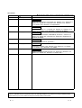
REVISIONS
The manual number is given on the bottom left of the back cover.
Print Date
Jun., 2001
Feb., 2002
Manual Number
SH (NA)-080171-A First edition
SH (NA)-080171-B Modifications
Revision
About Manuals, Section 2.3, Section 2.4, Section 4.6.1, Section 5.3,
Section 5.7, Section 6.2.2, Section 8.2.3, Section 8.2.4, Section
8.2.5, Section 8.2.6, Section 10.3, Appendix 8
Jul., 2002
SH (NA)-080171-C
Modifications
CONTENS, Section .1.1.1, Section 4.2, Section 11.3, Section 11.4,
Section 11.5, Section 13.2, Appendix 2, Appendix 8, INDEX
Feb., 2003
SH (NA)-080171-D
Modifications
SAFETY INSTRUCTIONS, CONTENTS, Section 2.1, Section 3.1,
Section 5.3, Section 6.2.2, Section 6.4, Section 6.5, Appendix 3.3,
Appendix 8, INDEX
May, 2003
SH (NA)-080171-E
Oct., 2003
SH (NA)-080171-F
Modifications
CONTENTS, Appendix 6, Appendix 7
Modifications
CONTENTS, Section 1.2.2, Section 3.3.2, Section 3.4.3, Section
3.4.4, Section 7.5.3, Section 9.1.2, INDEX
Jun., 2004
SH (NA)-080171-G
Modifications
SAFETY PRECAUTIONS, Section 2.4, Section 2.5, Section 3.4.3,
Section 5.1, Section 5.7, Section 6.4, Section 6.6.1
Japanese Manual Version SH-080138-H
This manual confers no industrial property rights or any rights of any other kind, nor does it confer any patent
licenses. Mitsubishi Electric Corporation cannot be held responsible for any problems involving industrial property
rights which may occur as a result of using the contents noted in this manual.
2001 MITSUBISHI ELECTRIC CORPORATION
A-4
A-4
INTRODUCTION
Thank you for purchasing the Mitsubishi programmable logic controller MELSEC-Q Series.
Always read through this manual, and fully comprehend the functions and performance of the Q Series PLC
before starting use to ensure correct usage of this product.
CONTENTS
SAFETY INSTRUCTIONS.............................................................................................................................A- 1
REVISIONS ....................................................................................................................................................A- 4
INTRODUCTION............................................................................................................................................A- 5
CONTENTS....................................................................................................................................................A- 5
About Manuals ...............................................................................................................................................A- 9
Using This Manual..........................................................................................................................................A- 9
Conformation to the EMC Directive and Low Voltage Instruction ................................................................A- 9
Generic Terms and Abbreviations ................................................................................................................A- 10
Component List .............................................................................................................................................A- 10
SECTION 1 PRODUCT SPECIFICATIONS AND HANDLING
1 PRODUCT OUTLINE
1- 1 to 1- 14
1.1 Positioning control.................................................................................................................................... 1- 1
1.1.1 Features of QD70.............................................................................................................................. 1- 1
1.1.2 Mechanism of positioning control ..................................................................................................... 1- 2
1.1.3 Outline design of positioning control system.................................................................................... 1- 4
1.1.4 Communicating signals between QD70 and each module.............................................................. 1- 8
1.2 Positioning control................................................................................................................................... 1- 10
1.2.1 Outline of starting ............................................................................................................................. 1- 10
1.2.2 Outline of stopping ........................................................................................................................... 1- 12
2 SYSTEM CONFIGURATION
2- 1 to 2- 7
2.1 General image of system......................................................................................................................... 22.2 Component list ......................................................................................................................................... 22.3 Applicable system .................................................................................................................................... 22.4 How to check the function version and the software version ................................................................. 22.5 About Use of the QD70 on the MELSECNET/H Remote I/O Station .................................................... 23 SPECIFICATIONS AND FUNCTIONS
1
2
3
5
6
3- 1 to 3- 13
3.1 Performance specifications...................................................................................................................... 3- 1
3.2 List of functions ........................................................................................................................................ 3- 2
3.3 Specifications of input/output signal with PLC CPU ............................................................................... 3- 4
3.3.1 List of input/output signals with PLC CPU........................................................................................ 3- 4
3.3.2 Details of input signal (QD70 PLC CPU) ..................................................................................... 3- 5
3.3.3 Details of output signals (PLC CPU QD70) ................................................................................. 3- 6
3.4 Specifications of input/output interfaces with external device ................................................................ 3- 7
3.4.1 Electrical specifications of input/output signals ................................................................................ 3- 7
3.4.2 Signal layout for external device connection connector................................................................... 3- 9
3.4.3 List of input/output signal details...................................................................................................... 3- 10
3.4.4 Input/output interface internal circuit................................................................................................ 3- 11
A-5
A-5
4 DATA USED FOR POSITIONING CONTROL(LIST OF BUFFER MEMORY ADDRESSES)
4- 1 to 4- 31
4.1 Type of data ............................................................................................................................................. 4- 1
4.1.1 Parameters and data required for control......................................................................................... 4- 1
4.1.2 Setting items for parameters............................................................................................................. 4- 3
4.1.3 Setting items for OPR data ............................................................................................................... 4- 4
4.1.4 Setting items for JOG data................................................................................................................ 4- 5
4.1.5 Setting items for positioning data...................................................................................................... 4- 6
4.1.6 Type and roles of monitor data ......................................................................................................... 4- 7
4.1.7 Type and roles of control data .......................................................................................................... 4- 8
4.2 List of parameters .................................................................................................................................... 4- 9
4.3 List of OPR data...................................................................................................................................... 4- 14
4.4 List of JOG data ...................................................................................................................................... 4- 20
4.5 List of positioning data ............................................................................................................................ 4- 21
4.6 List of monitor data.................................................................................................................................. 4- 27
4.6.1 Axis monitor data.............................................................................................................................. 4- 27
4.6.2 Module information monitor data ..................................................................................................... 4- 29
4.7 List of control data................................................................................................................................... 4- 30
4.7.1 Axis control data............................................................................................................................... 4- 30
5 SETUP AND PROCEDURES BEFORE OPERATION
5- 1 to 5- 20
5.1 Handling precautions ............................................................................................................................... 5- 1
5.2 Procedures before operation ................................................................................................................... 5- 3
5.3 Part identification nomenclature .............................................................................................................. 5- 4
5.4 Wiring ....................................................................................................................................................... 5- 7
5.4.1 Wiring precautions............................................................................................................................. 5- 7
5.5 Confirming the wiring .............................................................................................................................. 5- 12
5.5.1 Confirmation items at completion of wiring...................................................................................... 5- 12
5.6 Switch setting for intelligent function module ......................................................................................... 5- 14
5.7 Simple reciprocating operation ............................................................................................................... 5- 18
6 UTILITY PACKAGE(GX Configurator-PT)
6- 1 to 6- 17
6.1 Utility package functions .......................................................................................................................... 6- 1
6.2 Installing and uninstalling the utility package .......................................................................................... 6- 2
6.2.1 User precautions ............................................................................................................................... 6- 2
6.2.2 Operating environment...................................................................................................................... 6- 4
6.3 Explanation of utility package operations................................................................................................ 6- 5
6.3.1 How to perform common utility package operations........................................................................ 6- 5
6.3.2 Operation overview ........................................................................................................................... 6- 7
6.3.3 Starting the intelligent function module utility ................................................................................... 6- 9
6.4 Initial setting............................................................................................................................................. 6- 11
6.5 Auto refresh setting ................................................................................................................................. 6- 13
6.6 Monitor/test.............................................................................................................................................. 6- 15
6.6.1 Monitor/Test screen.......................................................................................................................... 6- 15
7 SEQUENCE PROGRAM USED FOR POSITIONING CONTROL
7- 1 to 7- 20
7.1 Precautions for creating program ............................................................................................................ 7- 1
7.2 List of devices used.................................................................................................................................. 7- 3
A-6
A-6
7.3 Creating a program .................................................................................................................................. 7- 5
7.3.1 General configuration of program..................................................................................................... 7- 5
7.3.2 Positioning control operation program.............................................................................................. 7- 6
7.4 Positioning control program examples .................................................................................................... 7- 8
7.5 Program details ....................................................................................................................................... 7- 12
7.5.1 Initialization program ........................................................................................................................ 7- 12
7.5.2 Start method setting program .......................................................................................................... 7- 13
7.5.3 Start program.................................................................................................................................... 7- 13
7.5.4 Sub program..................................................................................................................................... 7- 19
SECTION 2 CONTROL DETAILS AND SETTING
8 OPR CONTROL
8- 1 to 8- 16
8.1 Outline of OPR control ............................................................................................................................. 8- 1
8.1.1 Two types of OPR control ................................................................................................................. 8- 1
8.2 Machine OPR control............................................................................................................................... 8- 2
8.2.1 Outline of the machine OPR operation............................................................................................. 8- 2
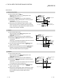
8.2.2 Machine OPR method....................................................................................................................... 8- 3
8.2.3 OPR method (1): Near-point dog method ........................................................................................ 8- 4
8.2.4 OPR method (2): Stopper 1 .............................................................................................................. 8- 6
8.2.5 OPR method (3): Stopper 2 .............................................................................................................. 8- 8
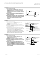
8.2.6 OPR method (4): Stopper 3 ............................................................................................................. 8- 10
8.2.7 OPR method (5): Count 1 ................................................................................................................ 8- 12
8.2.8 OPR method (6): Count 2 ................................................................................................................ 8- 14
8.3 Fast OPR control..................................................................................................................................... 8- 16
8.3.1 Outline of the fast OPR control operation........................................................................................ 8- 16
9 POSITIONING CONTROL
9- 1 to 9- 17
9.1 Outline of positioning controls.................................................................................................................. 9- 1
9.1.1 Data required for positioning control................................................................................................. 9- 1
9.1.2 Operation patterns of positioning controls........................................................................................ 9- 2
9.1.3 Designating the positioning address................................................................................................. 9- 8
9.1.4 Confirming the current value............................................................................................................. 9- 9
9.2 Setting the positioning data .................................................................................................................... 9- 10
9.2.1 Relation between each control and positioning data ...................................................................... 9- 10
9.2.2 1-axis linear control .......................................................................................................................... 9- 11
9.2.3 Speed-position switching control ..................................................................................................... 9- 13
9.2.4 Current value changing .................................................................................................................... 9- 16
9.3 Multiple axes simultaneous start control ................................................................................................ 9- 17
10 JOG OPERATION
10- 1 to 10- 6
10.1 Outline of JOG operation ..................................................................................................................... 10- 1
10.2 JOG operation execution procedure ................................................................................................... 10- 3
10.3 JOG operation example....................................................................................................................... 10- 4
11 SUB FUNCTIONS
11- 1 to 11- 13
11.1 Outline of sub functions ....................................................................................................................... 11- 1
A-7
A-7
11.2 Speed limit function.............................................................................................................................. 11- 1
11.3 Speed change function ........................................................................................................................ 11- 2
11.4 Software stroke limit function............................................................................................................... 11- 5
11.5 Acceleration/deceleration processing function.................................................................................... 11- 8
11.6 Restart function ................................................................................................................................... 11- 12
12 COMMON FUNCTIONS
12- 1 to 12- 3
12.1 Outline of common functions ............................................................................................................... 12- 1
12.2 External I/O signal switching function.................................................................................................. 12- 1
12.3 External I/O signal monitor function .................................................................................................... 12- 2
13 TROUBLESHOOTING
13- 1 to 13- 14
13.1 Error and warning details..................................................................................................................... 13- 1
13.2 List of errors ......................................................................................................................................... 13- 3
13.3 List of warnings ................................................................................................................................... 13- 11
13.4 LED display function ........................................................................................................................... 13- 13
13.5 Confirming the error definition using system monitor of GX Developer............................................ 13- 14
APPENDIX
App- 1 to App- 18
Appendix 1 External dimension drawing ...................................................................................................App- 1
Appendix 2 Operation timing and processing time in each control ..........................................................App- 2
Appendix 3 Connection examples with servo amplifiers manufactured by MITSUBISHI Electric Corporation
.................................................................................................................................................App- 6
Appendix 3.1 Connection example of QD70P and MR-H A...........................................................App- 6
and MR-J2/J2S- A................................................App- 7
Appendix 3.2 Connection example of QD70P
Appendix 3.3 Connection example of QD70P and MR-C A...........................................................App- 8
Appendix 4 Connection examples with stepping motors manufactured by ORIENTALMOTOR Co., Ltd.
.................................................................................................................................................App- 9
Appendix 4.1 Connection example of QD70P and VEXTA UPD .....................................................App- 9
Appendix 5 Connection examples with servo amplifiers manufactured by Matsushita Electric Industrial Co.,
Ltd...........................................................................................................................................App- 10
Appendix 5.1 Connection example of QD70P and MINAS-A series ...............................................App- 10
Appendix 6 Connection examples with servo amplifiers manufactured by SANYO DENKI Co., Ltd. ...App- 11
Appendix 6.1 Connection example of QD70P and PZ series ..........................................................App- 11
Appendix 7 Connection examples with servo amplifiers manufactured by YASKAWA Electric Corporation
................................................................................................................................................App- 12
Appendix 7.1 Connection example of QD70P and Σ- series .........................................................App- 12
Appendix 8 Comparisons with type QD75 positioning module................................................................App- 13
Appendix 9 List of buffer memory addresses...........................................................................................App- 16
INDEX
A-8
Index- 1 to Index- 5
A-8
About Manuals
The following manuals are also related to this product.
In necessary, order them by quoting the details in the tables below.
Detailed Manuals
Manual Number
(Model Code)
Manual Name
Type QD70 Positioning Module User's Manual (Hardware)
Describes the performance, specifications, I/O interface, component names, and startup procedure of
IB-0800169
(13JT42)
the respective positioning modules: QD70P4 and QD70P8. (The manual is supplied with the module.)
Using This Manual
The symbols used in this manual are shown below.
Pr.
...... Symbol indicating positioning parameter and OPR parameter item.
OPR. ....... Symbol indicating OPR data item.
JOG. ....... Symbol indicating JOG data item.
Da.
...... Symbol indicating positioning data item.
Md.
...... Symbol indicating monitor data item.
Cd. ....... Symbol indicating control data item.
(A serial No. is inserted in the
mark.)
Numeric values used in this manual
• The buffer memory addresses, error codes and warning codes are represented
in decimal.
• The X/Y devices are represented in hexadecimal.
• The setting data and monitor data are represented in either decimal or
hexadecimal. The data ended by "H" are represented in hexadecimal.
(Example) 10.........10 Decimal
10H ......16 Hexadecimal
Conformation to the EMC Directive and Low Voltage Instruction
For details on making Mitsubishi PLC conform to the EMC directive and low
voltage instruction when installing it in your product, please refer to Chapter 3,
“EMC Directive and Low Voltage Instruction” of the using PLC CPU module
User’s Manual (Hardware).
The CE logo is printed on the rating plate on the main body of the PLC that
conforms to the EMC directive and low voltage instruction.
To make this product conform to the EMC directive and low voltage instruction,
please refer to Section 5.4.1 "Wiring precautions".
A-9
A-9
Generic Terms and Abbreviations
Unless specially noted, the following generic terms and abbreviations are used in
this manual.
Generic term/abbreviation
Details of generic term/abbreviation
PLC CPU
Generic term for PLC CPU on which QD70 can be mounted.
AD75
Generic term for type A1SD75P1-S3/P2-S3/P3-S3, AD75P1-S3/P2-S3/P3-S3 Positioning
module.
The module type is described to indicate a specific module.
QD70
Generic term for type QD70 positioning module QD70P4/QD70P8.
The module type is described to indicate a specific module.
QD75
Generic term for positioning module QD75P1, QD75P2, QD75P4, QD75D1, QD75D2, and
QD75D4.
The module type is described to indicate a specific module.
Peripheral device
Generic term for DOS/V personal computer where following "GX Configurator-PT" and ""GX
Developer" have been installed.
GX Configurator-PT
Abbreviation for GX Configurator-PT (SW1D5C-QPTU-E) utility package for QD70 positioning
module.
GX Developer
Abbreviation for GX Developer (SW4D5C-GPPW-E or later).
Drive unit
Abbreviation for open collector pulse input compatible drive unit (servo amplifier or stepping
motor).
®
DOS/V personal computer IBM PC/AT and compatible DOS/V compliant personal computer.
Personal computer
Generic term for DOS/V personal computer.
Workpiece
Generic term for moving body such as workpiece and tool, and for various control targets.
Axis 1, axis 2, axis 3,
axis 4, axis 5, axis 6,
axis 7, axis 8
Indicates each axis connected to QD70.
1-axis, 2-axes, 3-axes,
4-axes, 5-axes, 6-axes,
7-axes, 8-axes
Indicates the number of axes. (Example: 2-axes = Indicates two axes such as axis 1 and axis
2, axis 2 and axis 3, and axis 3 and axis 1.)
Component List
The component list of this product is given below.
Type
Component
Quantity
QD70P4
Type QD70P4 Positioning Module (4-axes open-collector output type)
QD70P8
Type QD70P8 Positioning Module (8-axes open-collector output type)
1
SW1D5C-QPTU-E
GX Configurator-PT Version 1 (1-license product)
(CD-ROM)
1
SW1D5C-QPTU-EA
GX Configurator-PT Version 1 (Multiple-license product)
(CD-ROM)
1
A - 10
1
A - 10
SECTION 1
SECTION 1 PRODUCT SPECIFICATIONS
AND HANDLING
Section 1 is configured for the following purposes (1) to (4).
(1) To understand the outline of positioning control, and the QD70 specifications
and functions
(2) To carry out actual work such as installation and wiring
(3) To set parameters and data required for positioning control
(4) To create a sequence program required for positioning control
Read "Section 2" for details on each control.
CHAPTER 1 PRODUCT OUTLINE ................................................................................. 1- 1 to 1- 14
CHAPTER 2 SYSTEM CONFIGURATION ..................................................................... 2- 1 to 2- 7
CHAPTER 3 SPECIFICATIONS AND FUNCTIONS ...................................................... 3- 1 to 3- 13
CHAPTER 4 DATA USED FOR POSITIONING CONTROL.......................................... 4- 1 to 4- 31
CHAPTER 5 SETUP AND PROCEDURES BEFORE OPERATION............................. 5- 1 to 5- 20
CHAPTER 6 UTILITY PACKAGE.................................................................................... 6- 1 to 6- 17
CHAPTER 7 SEQUENCE PROGRAM USED FOR POSITIONING CONTROL........... 7- 1 to 7- 20
SECTION 1
MEMO
1 PRODUCT OUTLINE
MELSEC-Q
CHAPTER 1 PRODUCT OUTLINE
This User's Manual provides the specifications, handling, programming methods and
other information of the QD70 positioning module used with the MELSEC-Q series
CPU module.
When diverting any of the program examples introduced in this manual to the actual
system, fully verify that there are no problems in the controllability of the target system.
1.1 Positioning control
1.1.1 Features of QD70
The following are the features of the QD70.
(1) Wide assortment of 4-axes and 8-axes modules
The QD70 is a positioning module used in a multi-axes system that does not
need complex control.
It is not compatible with the MELSEC-A series AD70 positioning module in I/O
signals, functions, etc.
(2) About positioning control functions
(a) The QD70 has a number of functions required for a positioning control
system, such as positioning control to any position and equal-speed control.
1) You can set up to 10 pieces of positioning data, which include
positioning address, control method, operation pattern and like, per axis.
These positioning data are used to exercise positioning control axis-byaxis.
2) Axis-by-axis positioning control allows linear control (up to 8 axes can be
controlled simultaneously).
This control can perform positioning termination with one piece of
positioning data or exercise continuous positioning control by continuous
execution of multiple pieces of positioning data.
(b) As the control method, any of position control, speed-position switching
control and current value changing may be specified in each positioning
data.
(c) The following six different OPR methods are available for "machine OPR
control": near-point dog method (one method), stopper (three methods) and
count (two methods).
(d) Varying finely in speed to ensure smooth acceleration/deceleration, the
QD70 is suitable for connection to a stepping motor.
(e) You can change the I/O signal logic according to the specifications of the
external device.
This allows the input signals to be used with either of "normally open" and
"normally closed" contacts, and the output signals to be used according to
the specifications of the drive unit.
(3) Fast start processing
Processing at a position control start has been speeded up to shorten the start
processing time of one axis to 0.1ms.
At a simultaneous start of multiple axes (the positioning start signals are turned
ON at the same time within one scan), there are no starting delays between the
axes.
(4) Ease of maintenance
In the QD70, error definitions have been subdivided to improve maintenance
performance.
(5) Ease of utility package settings
The optionally available utility package (GX Configurator-PT) allows initial setting
and auto refresh setting to be made on the screen, reducing sequence programs
and facilitating the confirmation of the setting status and operating status.
1-1
1-1
1
1 PRODUCT OUTLINE
MELSEC-Q
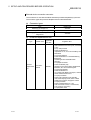
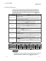
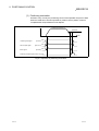
1.1.2 Mechanism of positioning control
1
Positioning control using the QD70 is exercised using "pulse signals". (The QD70 is a
module that outputs pulses.)
In a positioning control system using the QD70, a variety of software and external
devices are used to play their roles as shown below.
The QD70 imports various signals, parameters and data, and exercises control with
the PLC CPU to realize complex positioning control.
Stores the created program.
The QD70 outputs the positioning start signal and
axis stop signal following the stired program.
QD70 errors, etc., are detected.
Peripheral device
GX Developer/
GX Configurator-PT
Using GX Developer, create
control sequence and conditions
as sequence program.
Adding in GX Configurator-PT
enables initial setting of
parameters and data.
PLC CPU
Input near-point dog signal and speed
-position switching signal to QD70.
QD70
positioning
module
Mechanical
system inputs
(Switches)
Stores the parameter and data
Outputs to the drive unit according to the
instructins from the PLC CPU.
Drive
unit
Receives pulses commands from QD70,
and drives the motor.
Motor
Carries out the actual work according to
commands from the drive unit
Workpiece
1-2
1-2
1 PRODUCT OUTLINE
MELSEC-Q
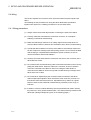
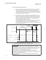
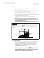
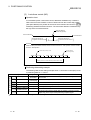
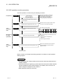
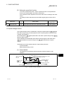
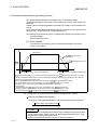
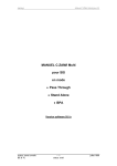
The principle of "position control" and "speed control" operation is shown below.
Position control
The total No. of pulses required to move the designated distance is obtained in the
following manner.
Total No. of pulses
required to move
designated distance
Designated distance
=
Movement amount of machine (load)
side when motor rotates once
No. of pulses
required for motor to
rotate once
The No. of pulses required for the motor to rotate once is the "encoder resolution"
described in the motor catalog specification list.
When this total No. of pulses is issued from the QD70 to the drive unit, control to move
the designated distance can be executed.
The machine side movement amount when one pulse is issued to the drive unit is
called the "movement amount per pulse". This value is the min. value for the workpiece
to move, and is also the electrical positioning control precision.
Speed control
Though the above "total No. of pulses" is an element needed to control the
movement amount, speed must be controlled to perform equal-speed operation.
This "speed" is controlled by the "pulse frequency" output from the QD70 to the drive
unit.
Pulse frequency
[pps]
Positioning
module
Servo
amplifiter
Servo
motor
This area is hte total
No. of commanded
pulses.
A
Detector
Pulse
encoder
Speed=Pulses frequency
Movement amount=No. of puleses
Feedback pulses=
Pulses generated by detector
Feedback pulses
ta
0.4
td
1.2
(s)
0.4
Movement amount t = 2
Fig. 1.1 Relationship between position control and speed control
POINT
• The "movement amount per pulse" is the value determined on the machine side.
(Refer to Section 1.1.3.)
• The QD70 uses the "total No. of pulses" to control the position, and uses the
"pulse frequency" to control the speed.
1-3
1-3
1 PRODUCT OUTLINE
MELSEC-Q
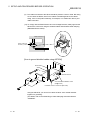
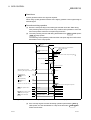
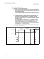
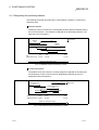
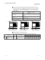
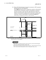
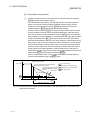
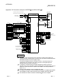
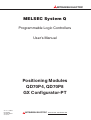
1.1.3 Outline design of positioning control system
The outline of the positioning control system operation and design, using the QD70, is
shown below.
(1) Positioning control system using QD70
PLC CPU
Program
Intelligent
function module
parameter
Positioning module
QD70
Forward run
pulse train
Read, write, etc.
Monitor date read
Buffer
memories Reverse run
pulse train
/XY
device
Drive unit
Deviation
counter
D/A
converter
Servomotor
Speed
command Servo
amplifiter
M
Interface
PLG
Feedback pulse
Initial setting /Auto rofresh setting/Monitor
GX Configurator-PT
Fig. 1.2 Outline of the operation of positioning control system using QD70
(a) Positioning operation by the QD70
1) The QD70 output is a pulse train.
The pulse train output by the QD70 is counted by and stored in the
deviation counter in the drive unit.
The D/A converter outputs an analog DC current proportionate to the
count maintained by the deviation counter (called "pulse droop"). The
analog DC current serves as the servomotor speed control signal.
2) The servomotor rotation is controlled by the speed control signal from
the drive unit.
As the servomotor rotates, the pulse encoder (PLG) attached to the
servomotor generates feedback pulses, the frequency of which is
proportionate to the rotation speed.
The feedback pulses are fed back to the drive unit and decrements the
pulse droop, the pulse count maintained by the deviation counter.
The motor keeps on rotating as the pulse droop is maintained at a
certain level.
3) When the QD70 terminates the output of a pulse train, the servomotor
decelerates as the pulse droop decreases and stops when the count
drops to zero.
Thus, the servomotor rotation speed is proportionate to the pulse
frequency, while the overall motor rotation angle is proportionate to the
total number of pulses output by the QD70.
Therefore, when a movement amount per pulse is given, the overall
movement amount can be determined by the number of pulses in the
pulse train.
The pulse frequency, on the other hand, determines the servomotor
rotation speed (feed speed).
1-4
1-4
1 PRODUCT OUTLINE
MELSEC-Q
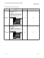
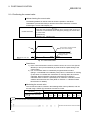
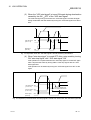
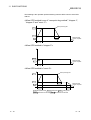
(b) Pulse train output from the QD70
1) As shown in Fig. 1.3, the pulse frequency increases as the servomotor
accelerates. The pulses are sparse when the servomotor starts and
more frequent when the servomotor speed comes close to the target
speed.
2) The pulse frequency stabilizes when the motor speed equals the target
speed.
3) The QD70 decreases the pulse frequency (sparser pulses) to
decelerate the servomotor before it finally stops the output.
There will be a little difference in timing between the decrease in the
pulse frequency and the actual deceleration and stopping of the
servomotor.
This difference, called "the stop settling time", is required for gaining a
stopping accuracy.
Servomotor
speed
Speed V
Pulse droop
amount
Pulse
distribution
Acceleration
Deceleration
Time t
Stop
setting time
Pulse train Rough
Rough
Dense
Fig. 1.3 QD70 output pulses
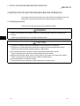
(2) Movement amount and speed in a system using worm gears
V
Workpiece
Worm pear
Pulse encoder
(PLG)
Table
Servomotor
P0
L
P
A
Vs
n
L
R
V
N
K
:
:
:
:
:
:
:
:
Movement amount per pulse (mm/pulse)
Command pulse frequency (pulse/s)
Pulse encoder resolution (pulse/rev)
Worm gear lead (mm/rev)
Deceleration ratio
Movable section speed (mm/s)
Motor speed (r/min)
Position loop gain (1/s)
ε : Deviation counter droop pulse amount
P0 : OP (pulse)
P : Address (pulse)
Fig. 1.4 System using worm gears
1-5
1-5
1 PRODUCT OUTLINE
MELSEC-Q
In the system shown in Fig. 1.4, the movement amount per pulse,
command pulse frequency, and the deviation counter droop pulser amount
are determined as follows:
1) Movement amount per pulse
The movement amount per pulse is determined by the worm gear lead,
deceleration ratio, and the pulse encoder resolution.
The movement amount, therefore, is given as follows: (Number of
pulses output) × (Movement amount per pulse).
A=
L
R× n
[mm/pulse]
2) Command pulse frequency
The command pulse frequency is determined by the speed of the
moving part and movement amount per pulse.
Vs =
V
A
[pulse/s]
3) Deviation counter droop pulser amount.
The deviation counter droop pulser amount is determined by the
command pulse frequency and position loop gain.
ε=
1-6
Vs
K
[pulse]
1-6
1 PRODUCT OUTLINE
MELSEC-Q
MEMO
1-7
1-7
1 PRODUCT OUTLINE
MELSEC-Q
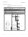
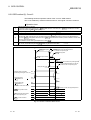
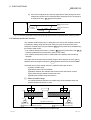
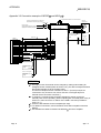
1.1.4 Communicating signals between QD70 and each module
The outline of the signal communication between the QD70 (positioning module) and
PLC CPU, peripheral device (GX Configurator-PT) and drive unit, etc., is shown below.
(A peripheral device communicates with the QD70 via the PLC CPU to which it is
connected)
Refer to Chapter 3 for details of the I/O signals.
QD70
PLC CPU
Y0
X0
PLC READY signal
Module READY signal
Zero signal
Y18 to Y1F
Drive
unit
JOG start signal
Deviation counter clear
Pulse train
Y8 to YF
X18 to X1F
X8 to XF
X10 to X17
Y10 to Y17
Positioning start
Positioning complete
signal
External
interface
Near-point dog singal
Mechanical
Speed-position switching system inputs
signal
(Switches)
BUSY signal
Start complete signal
Axis stop signal
Axis error occurrence
signal
X1
Axis warning occurrence
signal
X2
Interface
with
PLC CPU
24VDC
Power supply
(For pulse train output)
Date write/read
Peripheral
device
interface
Monitor data
Initial setting/Auto refresh/
Operation monitor
Peripheral device
(GX Configurator-PT)
1-8
1-8
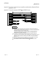
1 PRODUCT OUTLINE
QD70
MELSEC-Q
PLC CPU
The QD70 and PLC CPU communicate the following data via the base unit.
Direction
Communication
Control signal
PLC CPU
QD70
PLC CPU
QD70
Signal indication QD70 state.
Signal related to commands.
• Module READY (X0)
• PLC READY (Y0)
• Axis error occurrence (X1)
• Positioning start (Y8 to YF)
• Axis warning occurrence (X2)
• Axis stop (Y10 to Y17)
• BUSY (X8 to XF)
• JOG start (Y18 to Y1F)
• Start complete (X10 to X17)
• Positioning complete (X18 to X1F)
Data (read/write)
• Parameter
• Parameter
• OPR data
• OPR data
• JOG data
• JOG data
• Positioning data
• Positioning data
• Control data
• Control data
• Monitor data
QCPU
Peripheral device (GX Configurator-PT)
The QCPU and peripheral device make the following communications. (Refer to
Chapter 6 for details.)
Direction
Communication
QCPU
Peripheral device
Data
–
Peripheral device
• Initial setting
• Auto refresh setting
• Monitor data (QD70 buffer
Operation monitor
–
memory/XY devices)
QD70
QCPU
Drive unit
The QD70 and drive unit communicate the following data via the external device
connection connector.
Direction
QD70
Communication
Control signal
Drive unit
Drive unit
Signals related to commands
Signal indicating OP
• Deviation counter clear signal
• Zero signal (PG0)
QD70
(CLEAR)
Pulse train
• Pulse train output (PULSE F/
–
PULSE R)
: External 24VDC must be supplied to output the pulse train.
Mechanical system inputs (switches)
QD70
The input signals from the mechanical system inputs (switches) are entered into the
QD70 via the external device connection connector.
Mechanical system inputs (switches)
1-9
• Near-point dog signal (DOG)
• Speed-position switching signal (CHG)
1-9
1 PRODUCT OUTLINE
MELSEC-Q
1.2 Positioning control
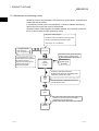
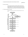
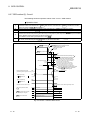
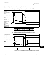
1.2.1 Outline of starting
The outline for starting each control is shown with the following flowchart.
It is assumed that each module is installed, and the required system configuration,
etc., has been prepared.
Flow of starting
Preparation
Control
functions
Installation and connection of module
Setting of hardware
Positioning control
Position control
Speed-position
switching control
Current value
changing
Parameter
Control data
Fast OPR control
( Pr. 1 to Pr. 10 )
Set the OPR data.
OPR. 1 to OPR. 9
Set the positioning data.
( Da. 1 to Da. 7 )
Set the start method.( Da. 1 to Da. 7 )
Set the JOG data
( JOG. 1 to JOG. 4 )
JOG data
Start signal
JOG operation
Machine OPR control
Set the parameters.
OPR data
Positioning
data
OPR control
Turn ON the QD70 start signal
from the PLC CPU
Turn the QD70 JOG
start signal ON from
the PLC CPU
: Positioning control can make a
multiple axes simultaneous start.
(Refer to "Section 9.3" for details.)
Control start
Operation
Control end
Stop
1 - 10
1 - 10
1 PRODUCT OUTLINE
MELSEC-Q
MEMO
1 - 11
1 - 11
1 PRODUCT OUTLINE
MELSEC-Q
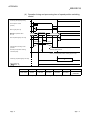
1.2.2 Outline of stopping
The possible causes of a control stop are as follows.
(1)
(2)
(3)
(4)
Control ended normally
An error occurred in the PLC CPU
An error occurred in the QD70
The axis stop signal from the PLC CPU turned ON
Stop processings performed in the above cases are outlined in the following table.
(Except the case (1) where control stopped normally)
Stopped
Stop factor
axis
PLC CPU error
Software stroke limit
QD70 error upper/lower limit error
1
Other error
"Axis stop signal" from PLC CPU turned
ON
Axis operation
status ( Md. 4 )
after stop
Stop processing
Positioning
OPR control
control
JOG operation
All axes
Error
Deceleration stop
Axis by axis
Error
Deceleration stop
Axis by axis
Error
Deceleration stop
2
Axis by axis
Stopped
Deceleration stop
3
1: By making parameter setting, you can set the software stroke limit valid/invalid. When the stroke limit is set invalid, a
deceleration stop is not made. (Refer to Section 4.2.)
2: If an illegal positioning data setting value caused an error during position control (operation pattern: continuous path
control), an immediate stop is made at the positioning data preceding that illegal setting value. (Refer to Section 9.1.2.)
3: For position control (operation pattern: continuous path control), you can make parameter setting to select the
stopping method (position match stop or deceleration stop). (Refer to Section 4.2.)
Stop after multiple axes simultaneous start under positioning control
The axes started will not stop simultaneously. The stop command (axis stop signal
ON) must be given to each axis.
1 - 12
1 - 12
1 PRODUCT OUTLINE
MELSEC-Q
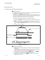
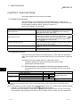
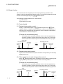
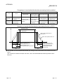
Pulse output operation at stop
When the axis stops due to stop cause occurrence, if there is the pulse being output
when the set deceleration stop time has elapsed from the start of deceleration stop,
the output as much as 1 pulse will be done.
The following shows the pulse output operation at deceleration stop.
Stop cause occurrence*4
(Start of deceleration stop)
V
Bias speed at start
*5
Set deceleration stop time
t
Pulse that is being output when set
deceleration stop time has elapsed
will be output. *7
Pulse output
1 pulse
ON
*6
BUSY signal
OFF
4: "Stop cause" indicates any of the following.
• Error occurred in the PLC CPU or QD70.
• JOG start signal (Y18 to Y1F) has turned OFF during JOG operation.
• Axis stop signal (Y10 to Y17) has turned ON.
• Speed change to speed 0 (pulse/s) (when bias speed at start is 0 (pulse/s))
• Machine OPR control of count 2
5: "Set deceleration stop time" is any of the following.
• During positioning control
: Da. 4
DEC/STOP time
• At speed change to speed 0 (pulse/s)
: Cd. 9
DEC/STOP time at speed change
• During machine OPR control of count 2 : OPR. 7 DEC/STOP time at OPR
• During JOG operation
: JOG. 3 JOG DEC time
6: When the axis is decelerated to a stop by a speed change to speed 0 (pulse/s), the BUSY signal
does not turn OFF.
7: The same operation is performed when an immediate stop cause occurs during machine OPR
control (except the case of count 2).
1 - 13
1 - 13
1 PRODUCT OUTLINE
MELSEC-Q
MEMO
1 - 14
1 - 14
2 SYSTEM CONFIGURATION
MELSEC-Q
CHAPTER 2 SYSTEM CONFIGURATION
This chapter explains the system configuration of the QD70.
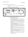
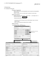
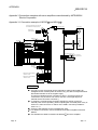
2.1 General image of system
The following is the general configuration including the QD70, PLC CPU, peripheral
device and others.
(The numbers in the sketch correspond to the "Nos." in the table in "Section 2.2
Component list" on the next page.)
Peripheral device
3
Personal
computer
2
GX Developer
(SW D5C-GPPW-E)
GX Configurator-PT
(SW D5C-QPTU-E)
4
RS-232
cable
5
USB cable
CPU module
Power supply
module 2
1
Main base unit
2
Extension
cable
Mechanical system inputs (switches)
Near-point dog signal
Speed-position switching signal
1
Positioning module
QD70P4/QD70P8
6
7
Drive
unit
Connection
cable
Motor
Extension system
REMARK
1: For the usable CPU module, refer to "Section 2.3 Applicable system".
2: For the usable base unit and power supply module, refer to the CPU Module
User's Manual.
2-1
2-1
2
2 SYSTEM CONFIGURATION
MELSEC-Q
2.2 Component list
A positioning system using the QD70 consists of the following components.
No.
Product
Type
Remarks
2
QD70P
1
Positioning module
QD70P4
No. of control axes
QD70P8
P
2
3
GX Developer
Open collector output type
SW D5C-GPPW-E For details, refer to the GX Developer Operating Manual and
GX Configurator-PT SW D5C-QPTU-E "CHAPTER 6 UTILITY PACKAGE (GX Configurator-PT)".
Personal computer
DOS/V personal
(User-prepared)
computer
Refer to the GX Developer Operating Manual for details.
(User-prepared)
4
RS-232 cable
RS-232 cable for connection of the CPU module and DOS/V personal
QC30R2
computer.
Refer to the GX Developer Operating Manual for details.
(User-prepared)
5
USB cable
–
USB cable for connection of the CPU module and DOS/V personal
computer.
Refer to the GX Developer Operating Manual for details.
6
Drive unit
–
(User-prepared)
Refer to the drive unit manual for details.
(User-prepared)
Cable for connection of the QD70 and drive unit or mechanical system
Connection cable
7
(for connection of
QD70 and drive unit)
–
input signals.
(To be fabricated in reference to the connected device manual and
Section 3.4.2)
2-2
2-2
2 SYSTEM CONFIGURATION
MELSEC-Q
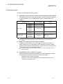
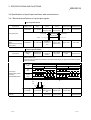
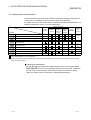
2.3 Applicable system
The QD70 is usable with the following system.
(1) Applicable module and the number of modules that can be installed
The following are the CPU module and network module (for remote I/O stations)
in which the QD70 can be installed and the number of modules that can be
installed.
Applicable module
CPU module
Network module
Q00JCPU
Q00CPU
Q01CPU
Q02CPU
Q02HCPU
Q06HCPU
Q12HCPU
Q25HCPU
Q12PHCPU
Q25PHCPU
QJ72LP25-25
QJ72BR15
QJ72LP25G
QJ71LP25GE
Number of modules that
can be installed
Maximum 16
Remarks
( 1)
Maximum 24
Maximum 64
Can be installed in Q mode only
( 1)
( 1)
Maximum 64
Maximum 64
MELSECNET/H Remote I/O
station ( 2)
1 See User's Manual (Function Explanation, Program Fundamentals) for the CPU module to use.
2 See Q Corresponding MELSECNET/H Network System Reference Manual (Remote I/O
network).
(2) Base unit in which the QD70 can be installed
The QD70 can be installed in any I/O slot ( 3) of the base unit. However, a
power shortage may occur depending on the combination with other installed
modules and the number of modules used, so always take into consideration the
power supply capacity when installing modules.
3 Limited to the range of the number of I/O points in the CPU module and network module (for
remote I/O stations).
(3) Compatibility with a multiple PLC system
First read the QCPU (Q mode) User's Manual (Function Explanation, Program
Fundamentals) if the QD70 is used with a multiple PLC system.
Intelligent function module parameters
Perform PLC write of the intelligent function module parameters to the
control PLC of the QD70 only.
2-3
2-3
2 SYSTEM CONFIGURATION
MELSEC-Q
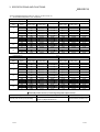
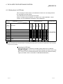
(4) Software packages supported
Correspondence between systems which use a QD70 and software packages
are as shown below.
The GX Developer is necessary when using a QD70.
Software Version
GX Developer
Single PLC
system
Version 7 or later
Multiple PLC
system
Version 8 or later
Single PLC
system
Version 4 or later
Multiple PLC
system
Version 6 or later
GX Configurator-PT
Q00J/Q00/Q01CPU
Q02/Q02H/Q06H/
Q12H/Q25HCPU
Version 1.10L or later
Single PLC
system
Q12PH/Q25PHCPU
Version 7.10L or later
Version 1.13P or later
Version 6 or later
Version 1.10L or later
Multiple PLC
system
If installed in a MELSECNET/H remote I/O
station
2-4
2-4
2 SYSTEM CONFIGURATION
MELSEC-Q
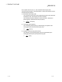
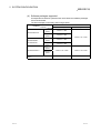
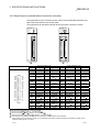
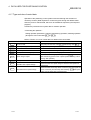
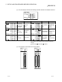
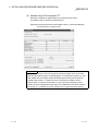
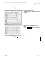
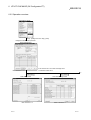
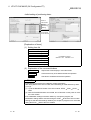
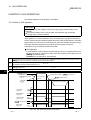
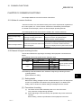
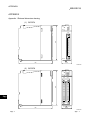
2.4 How to check the function version and the software version
The function version of the QD70 and the software version of the GX Configurator-PT
can be checked in the following methods.
[1] How to check the function version of the QD70
(a) Method using the rated plate on the module side face
Check the alphabet at the end of "SERIAL".
Serial No. (First 5 digits)
Function version
B
Conformed standard
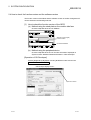
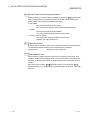
(b) Method using the peripheral device
Check the alphabet at the end of "Product information" displayed on
System monitor "Module's Detailed Information" of GX Developer.
[Operation of GX Developer]
Choose [Diagnostics]
[System monitor]
"QD70 module" and choose
Module's Detailed Information .
<GX Developer display screen>
Function version
2-5
2-5
2 SYSTEM CONFIGURATION
MELSEC-Q
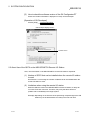
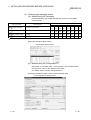
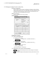
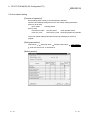
[2] How to check the software version of the GX Configurator-PT
Check the "Product information" displayed on "Help" of GX Developer.
[Operation of GX Developer]
Choose [Help]
Product information
<GX Developer display screen>
Software version
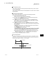
2.5 About Use of the QD70 on the MELSECNET/H Remote I/O Station
Here, use of the QD70 on the MELSECNET/H remote I/O station is explained.
(1) Number of QD70 that can be installed when the remote I/O station
is used
See Section 2.3 concerning the number of QD70 that can be installed when the
remote I/O station is used.
(2) Limitations when using the remote I/O station
When the QD70 is used on the MELSECNET/H remote I/O station, a delay will
occur due to the link scan time. Therefore, fully verify that there will be no
problem with controllability in the target system.
Example) Depending on the ON time of the positioning completed signal, the ON
status may not be detected due to a delay in the link scan time.
2-6
2-6
2 SYSTEM CONFIGURATION
MELSEC-Q
MEMO
2-7
2-7
3 SPECIFICATIONS AND FUNCTIONS
MELSEC-Q
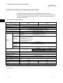
CHAPTER 3 SPECIFICATIONS AND FUNCTIONS
This chapter describes the performance specifications of the QD70 and the
specifications of the I/O signals transferred to/from the PLC CPU and external device.
For the general specifications of the QD70, refer to the User's Manual (hardware) of
the CPU module used.
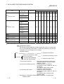
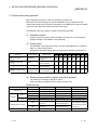
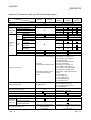
3 3.1 Performance specifications
Model
Item
No. of control axes
Interpolation function
Control method
Control unit
QD70P4
QD70P8
4 axes
8 axes
No
PTP (Point To Point) control, path control (linear only), speed-position switching control
pulse
10 pieces of data (positioning data No. 1 to 10)/axis
1
Positioning data
(can be set using GX Configurator-PT or sequence program)
Peripheral device/utility package
GX Configurator-PT (option)
Data backup
No
PTP control
: Incremental system/absolute system
Positioning
Speed-position switching control : Incremental system
control method
Path control
: Incremental system/absolute system
[Absolute system]
-2147483648 to 2147483647pulse
Positioning
[Incremental system]
control range
-2147483648 to 2147483647pulse
Positioning
[Speed-position switching control]
control
0 to 2147483647pulse
Speed command
0 to 200000pulse/s
Acceleration/
Trapezoidal acceleration/deceleration
deceleration
processing
Acceleration/
0 to 32767ms
deceleration time
1-axis start
0.1ms
2
Starting time
Position control
4-axes simultaneous start
0.2ms
8-axes simultaneous start
0.4ms
External wiring connection system
40-pin connector
2
Applicable wire size
0.3mm (for use of A6CON1 or A6CON4), AWG#24 (for use of A6CON2)
External device connection
A6CON1, A6CON2, A6CON4 (option)
connector
Pulse output method
Open collector output
Max. output pulse
200kpps
Max. connection distance between
2m
QD70 and drive unit
Internal current consumption (5VDC)
0.55A
0.74A
External 24V current consumption
0.065A
0.12A
(24VDC)
No. of occupied I/O points
32 points (I/O assignment: Intelligent function module 32 points)
Weight
0.15kg
0.17kg
1: Positioning data can be started from No.1 only. (Cannot be started from any of No.2 to No.10.)
2: A delay may occur depending on the operating conditions and starting conditions (control method, bias speed, ACC/DEC time, etc.) of
the other axes.
3-1
3-1
3 SPECIFICATIONS AND FUNCTIONS
MELSEC-Q
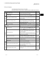
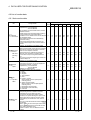
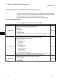
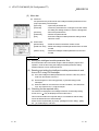
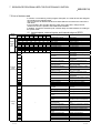
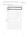
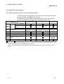
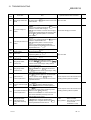
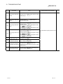
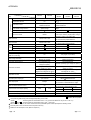
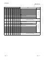
3.2 List of functions
The following table lists the functions of the QD70.
(Read "SECTION 2 CONTROL DETAILS AND SETTING" for details of the functions.)
Positioning control
OPR control
Function name
Sub function
Reference
Machine OPR control
Mechanically establishes the positioning control start
point using a near-point dog or stopper.
Section
8.2
Fast OPR control
Positions a target to the OP address ( Md. 1 Current feed
value) stored in the QD70 using machine OPR control.
Section
8.3
Position control (1-axis linear control)
Positions a target using a linear path to the address set in
the positioning data or to the position designated with the
movement amount.
Section
9.2.2
Speed-position switching control
First, carries out speed control, and then carries out
position control (positioning control with designated
address or movement amount) by turning the "speedposition switching signal" ON.
Section
9.2.3
Current value changing
Changes the Current feed value ( Md. 1 ) to the address
set in the positioning data.
Section
9.2.4
Outputs a pulse to drive unit while the JOG start signal is
ON.
Chapter
10
Speed limit function
If the command speed exceeds " Pr. 5 Speed limit value"
during control, this function limits the commanded speed
to within the " Pr. 5 Speed limit value" setting range.
Section
11.2
Speed change function
This function changes the speed at any point during
speed control of speed-position switching control or
during JOG operation.
Set the new speed in the speed change buffer memory
( Pr. 7 New speed value), and change the speed with the
Speed change request ( Pr. 6 ).
Section
11.3
Software stroke limit function
If a command outside of the upper/lower limit stroke limit
setting range, set in the parameters, is issued, this
function will not execute positioning for that command.
Section
11.4
Acceleration/deceleration processing function
This function adjusts the acceleration/deceleration
processing of control.
Section
11.5
Restart function
This function resumes positioning control during a stop of
the axis from where it had stopped.
Section
11.6
External I/O signal logic switching function
This function changes the external I/O signal logic to
match the externally connected device.
It can be changed by making the intelligent function
module switch setting.
Section
12.2
JOG operation
Common function
Description
External I/O signal monitor function
3-2
This function monitors the external I/O signal states using
GX Developer.
Section
5.5
Section
12.3
3-2
3
3 SPECIFICATIONS AND FUNCTIONS
MELSEC-Q
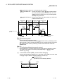
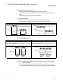
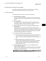
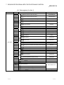
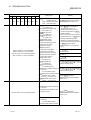
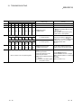
With the "positioning control", whether or not to continuously execute the positioning
data can be set with the "operation pattern". Outlines of the "operation patterns" are
given below.
Da.1 Operation pattern
Description
Reference
When "Positioning termination" is set for the operation pattern
Positioning termination
of the started positioning data, only the designated positioning
data will be executed, and then the positioning control will end.
When "continuous positioning control" is set for the operation
Continuous positioning control
pattern of the started positioning data, after the designated
positioning data is executed, the program will stop once, and
9.1.2
then the next following positioning data will be executed.
When "continuous path control" is set for the operation pattern
Continuous path control
of the started positioning data, the designated positioning data
will be executed, and then without decelerating, the next
following positioning data will be executed.
3-3
3-3
3 SPECIFICATIONS AND FUNCTIONS
MELSEC-Q
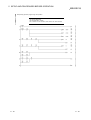
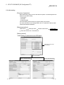
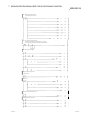
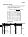
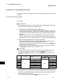
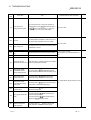
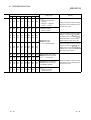
3.3 Specifications of input/output signal with PLC CPU
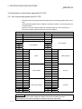
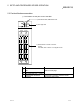
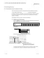
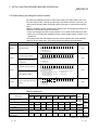
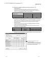
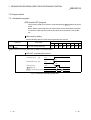
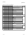
3.3.1 List of input/output signals with PLC CPU
The QD70 uses 32 input points and 32 output points for exchanging data with the PLC
CPU.
The input/output signals when the QD70 is mounted in slot No. 0 of the main base unit
are shown below.
Device X refers to the signals input from the QD70 to the PLC CPU, and device Y
refers to the signals output from the PLC CPU to the QD70.
Signal direction: QD70
PLC CPU
Signal direction: PLC CPU
QD70
Device No.
Signal name
Device No.
Signal name
X0
Module READY
Y0
PLC READY
X1
Axis error occurrence
Y1
X2
Axis warning occurrence
Y2
X3
Y3
X4
Y4
X5
Use prohibited
Use prohibited
Y5
X6
Y6
X7
Y7
X8
Axis 1
Y8
Axis 1
X9
Axis 2
Y9
Axis 2
XA
Axis 3
YA
Axis 3
XB
Axis 4
YB
Axis 4
XC
Axis 5
YC
Axis 5
BUSY
XD
Axis 6
YD
Axis 6
XE
Axis 7
YE
Axis 7
XF
Axis 8
YF
Axis 8
X10
Axis 1
Y10
Axis 1
X11
Axis 2
Y11
Axis 2
X12
Axis 3
Y12
Axis 3
X13
Axis 4
Y13
Axis 4
X14
Axis 5
Y14
Axis 5
X15
Axis 6
Y15
Axis 6
X16
Axis 7
Y16
Axis 7
X17
Axis 8
Y17
Axis 8
X18
Axis 1
Y18
Axis 1
X19
Axis 2
Y19
Axis 2
X1A
Axis 3
Y1A
Axis 3
X1B
Axis 4
Y1B
Axis 4
X1C
Axis 5
Y1C
Axis 5
X1D
Axis 6
Y1D
Axis 6
X1E
Axis 7
Y1E
Axis 7
X1F
Axis 8
Y1F
Axis 8
Start complete
Positioning complete
Positioning start
Axis stop
JOG start
Important
[Y1 to Y7], and [X3 to X7] are used by the system, and cannot be used by the user.
If these devices are used, the operation of the QD70 will not be guaranteed.
3-4
3-4
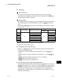
3 SPECIFICATIONS AND FUNCTIONS
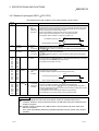
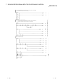
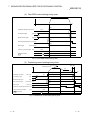
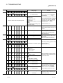
3.3.2 Details of input signal (QD70
MELSEC-Q
PLC CPU)
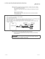
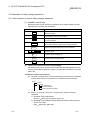
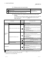
The ON/OFF timing and conditions of the input signals are shown below.
Device
Signal name
No.
X0
Module READY
ON: Prepared
OFF: Not
prepared
watch dog
timer error
Description
• When the PLC READY signal [Y0] turns from OFF to ON, the parameter and the
OPR data setting range is checked. If no error is found, this signal turns ON. (When
the axis error occurrence signal [X1] is ON, this signal does not turn ON if the PLC
READY signal [Y0] is turned from OFF to ON.)
• When the PLC READY signal [Y0] turns OFF, this signal turns OFF.
• When a watch dog timer (WDT) error occurs, this signal turns OFF.
• This signal is used for interlock in a sequence program, etc.
ON
PLC READY signal [Y0] OFF
ON
Module READY signal [X0] OFF
OFF: No error
• This signal turns ON if an error occurs in any of axes 1 to 8, and turns OFF when
ON: Error
" Cd. 1 Axis error reset" is set for all axes.
occurrence
(Use " Md. 10 Error status" to confirm the error status of the corresponding axis.)
OFF: No warning • This signal turns ON if a warning occurs in any of axes 1 to 8, and turns OFF when
ON: Warning
" Cd. 1 Axis error reset" is set for all axes.
occurrence
(Use " Md. 11 Warning status" to confirm the warning status of the corresponding
axis.)
OFF: Not BUSY • This signal turns ON at the start of positioning control, OPR control or JOG operation.
ON: BUSY
It turns OFF when the " Da. 7 Dwell time" has passed after positioning control stops.
(This signal remains ON during positioning control.)
• This signal turns OFF at error or stop.
X1
Axis error
occurrence
X2
Axis warning
occurrence
X8
X9
XA
XB
XC
XD
XE
XF
X10
X11
X12
X13
X14
X15
X16
X17
Axis 1 BUSY 1
Axis 2
Axis 3
Axis 4
Axis 5
Axis 6
Axis 7
Axis 8
Axis 1 Start
Axis 2 complete
Axis 3
Axis 4
Axis 5
Axis 6
Axis 7
Axis 8
X18
X19
X1A
X1B
X1C
X1D
X1E
X1F
Axis 1 Positioning OFF: Positioning
incomplete
Axis 2 complete 2
ON: Positioning
Axis 3
complete
Axis 4
Axis 5
Axis 6
Axis 7
Axis 8
OFF: Start
incomplete
ON: Start
complete
• This signal turns ON when the positioning start signal turns ON and the QD70 starts
the positioning control process.
(The start complete signal also turns ON during OPR control.)
ON
Positioning start signal [Y8] OFF
ON
Start complete signal [X10] OFF
• This signal turns ON for the time set in " Pr. 7 Positioning complete signal output
time" from completion of position control of the corresponding axis.
(It does not turn ON if 0 is set in " Pr. 7 Positioning complete signal output time".)
• While ON, this signal turns OFF if a positioning control start (including OPR control)
or JOG operation start is made.
• This signal does not turn ON at the termination of JOG operation.
• This signal does not turn ON if position control is stopped midway.
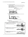
Important
1: The BUSY signal turns ON even when position control of movement amount 0 is
executed. However, since the ON time is short, the ON status may not be detected in the
sequence program.
2: "Position control complete" of the QD70 refers to the point when the pulse output from
QD70 is completed.
Thus, even if the QD70's positioning complete signal turns ON, the system may continue
operation.
3-5
3-5
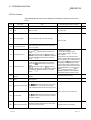
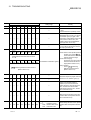
3 SPECIFICATIONS AND FUNCTIONS
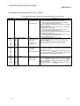
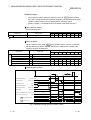
3.3.3 Details of output signals (PLC CPU
MELSEC-Q
QD70)
The ON/OFF timing and conditions of the output signals are shown below.
Device No.
Y0
PLC READY
Y8
Y9
YA
YB
YC
YD
YE
YF
Y10
Y11
Y12
Y13
Y14
Y15
Y16
Y17
Y18
Y19
Y1A
Y1B
Y1C
Y1D
Y1E
Y1F
3-6
Signal name
OFF:
PLC READY OFF
ON:
PLC READY ON
Axis 1 Positioning start
Axis 2
Axis 3
Axis 4
Axis 5
Axis 6
Axis 7
Axis 8
Axis 1 Axis stop
Axis 2
Axis 3
Axis 4
Axis 5
Axis 6
Axis 7
Axis 8
Axis 1 JOG start
Axis 2
Axis 3
Axis 4
Axis 5
Axis 6
Axis 7
Axis 8
OFF:
Positioning start not
requested
ON:
Positioning start
requested
Description
(a) This signal notifies the QD70 that the PLC CPU is normal.
• It is turned ON/OFF with the sequence program.
• The PLC READY signal is turned ON during positioning
control, OPR control and JOG operation.
(b) When parameters and OPR data are changed, the PLC READY
signal is turned OFF.
(c) The following processes are carried out when the PLC READY
signal turns from OFF to ON.
• The parameter and OPR data setting range is checked.
• The module READY signal [X0] turns ON.
(d) The following processes are carried out when the PLC READY
signal turns from ON to OFF.
In these cases, the OFF time should be set to 100ms or more.
• The module READY signal [X0] turns OFF.
• The operating axis stops.
• OPR control and positioning control is started.
• The positioning start signal is valid at the rising edge, and the
operation is started.
• When the positioning start signal turns ON during BUSY, the
operation starting warning will occur (warning code: 10).
OFF:
Axis stop not
requested
ON:
Axis stop requested
• When the axis stop signal turns ON, the OPR control, positioning
control and JOG operation. In these cases, the ON time should be
set to 4ms or more.
• Turning ON the axis stop signal during operation decelerates the
axis to a stop. At this time, " Md. 4 Axis operation status" changes
from "Deceleration (Axis Stop ON)" to "Stopped".
OFF:
JOG not started
ON:
JOG started
• When the JOG start signal is ON, JOG operation will be carried
out at the " JOG. 1 JOG speed". When the JOG start signal turns
OFF, the operation will decelerate and stop. At this time, " Md. 4
Axis operation status" changes from "Deceleration (JOG Start
OFF)" to "Standby".
• Set the rotation direction in " JOG. 4 JOG direction flag". (Refer to
Chapter 10.)
3-6
3 SPECIFICATIONS AND FUNCTIONS
MELSEC-Q
3.4 Specifications of input/output interfaces with external device
3.4.1 Electrical specifications of input/output signals
Input specifications
Signal name
Rated input
voltage/current
Working voltage
range
5VDC/18mA
4.5 to 5.5VDC
ON voltage/
current
OFF voltage/
current
2.7VDC or more/ 1.0VDC or less/
5.5mA or more
0.5mA or less
Input resistance
Response time
Approx. 270Ω
0.1ms or less
ON
Zero signal (PG0)
3µs or less
3µs or less
1ms or more
OFF
Near-point dog signal
(DOG)
Speed-position switching
signal (CHG)
24VDC/5mA
17.5VDC or
more/3mA or
more
19.2 to 26.4VDC
7VDC or less/
0.9mA or less
Approx. 6.8kΩ
1ms or less
Output specifications
Signal name
Max. load
Max. voltage
Leakage current
Response time
current/rush
drop at ON
at OFF
current
• Set the pulse output mode and pulse output logic selection in "intelligent function module switch setting"
(Refer to Section 5.6).
• The following are the relationships between pulse outputs depending on the "pulse output mode" and "pulse
output logic selection".
Rated load
voltage
Working load
voltage range
Pulse output logic selection
Pulse output
mode
Positive logic
Forward run
Pulse output
(CW/PULSE/A phase)
Pulse sign
(CCW/SIGN/B phase)
Negative logic
Reverse run
Forward run
Reverse run
CW
CCW
PULSE
SIGN
High
Low
Low
High
The table next page shows the rising/falling edge time and duty ratio.
ON
OFF
tr
Deviation counter clear
(CLEAR)
3-7
5 to 24VDC
4.75 to 30VDC
5 to 24VDC
4.75 to 30VDC
tf
50mA/1 point/
200mA 10ms or
less
0.1A/1 point/0.4A
10ms or less
0.5VDC (TYP)
0.1mA or less
—
1VDC (TYP)
2.5VDC (MAX)
0.1mA or less
2ms or less
(resistance load)
3-7
3 SPECIFICATIONS AND FUNCTIONS
MELSEC-Q
: Pulse rising/falling edge time (Unit for "tr" and "tf": µs, unit for "Duty": %)
... When ambient temperature is room temperature.
Load voltage (V)
Cable length (m)
Load current Pulse speed
(mA)
(kpps)
2
5
10
20
50
200
100
10
200
100
10
200
100
10
200
100
10
200
100
10
Load voltage (V)
Cable length (m)
Load current Pulse speed
(mA)
(kpps)
2
5
10
20
50
200
100
10
200
100
10
200
100
10
200
100
10
200
100
10
26.4
tr
(Rising edge)
1
tf
(Falling edge)
1.902
2.869
3.710
1.776
2.134
2.357
1.336
1.644
2.028
1.236
1.772
1.957
1.122
1.359
1.750
0.3178
0.3388
0.3616
0.3036
0.3285
0.3982
0.3174
0.3814
0.4197
0.3807
0.4453
0.4776
0.6809
0.7407
0.9833
tr
(Rising edge)
1
tf
(Falling edge)
0.8352
1.880
1.942
1.220
1.422
1.705
0.8736
1.041
1.576
1.021
1.277
1.473
0.8312
0.9714
0.9884
0.2093
0.2679
0.2765
0.1726
0.2652
0.2893
0.2739
0.3075
0.3295
0.3479
0.3671
0.4207
0.6302
0.6290
0.7037
Duty
tr
(Rising edge)
2
tf
(Falling edge)
28.20
38.44
50.22
35.45
43.90
50.88
40.92
48.05
51.31
45.64
49.90
51.63
51.78
53.09
52.05
2.129
3.691
5.187
1.763
2.394
3.105
1.429
1.812
1.996
1.269
1.734
1.727
1.019
1.544
1.819
0.2724
0.3549
0.3613
0.3395
0.3445
0.3899
0.3228
0.3793
0.4200
0.3949
0.4660
0.4749
0.6684
0.7897
0.9130
Duty
tr
(Rising edge)
2
tf
(Falling edge)
45.21
44.44
51.03
39.35
48.15
51.35
46.99
49.87
51.49
49.65
51.67
51.84
55.37
55.38
52.09
1.484
1.848
2.039
1.191
1.589
1.604
1.167
1.371
1.672
0.7345
1.222
1.287
0.7978
1.025
1.105
0.1924
0.2536
0.2873
0.2345
0.2631
0.3116
0.2519
0.3028
0.3212
0.3452
0.3780
0.3999
0.5752
0.6218
0.6799
Duty
28.09
40.12
49.63
36.48
41.11
50.50
40.44
46.40
51.22
45.14
49.73
51.55
51.42
52.90
52.03
4.75
Duty
36.94
45.03
51.13
41.56
47.89
51.40
44.97
50.02
51.41
48.94
52.12
51.73
55.34
55.64
52.05
External power source (For driving the pulse output circuit)
Signal name
External power source input (+24V/24G)
3-8
Rated input voltage
24VDC
(+20%/-15) (Ripple rate within 5%)
Current consumption
QD70P4:0.065A, QD70P8:0.12A
3-8
3 SPECIFICATIONS AND FUNCTIONS
MELSEC-Q
3.4.2 Signal layout for external device connection connector
The specifications of the connector section, which is the input/output interface for the
QD70 and external device, are shown below.
The signal layout for the QD70 external device connection connector is shown.
QD70P4
RUN
QD70P8
AX1
AX2
AX3
AX4
ERR.
RUN
ERR.
AX5
AX6
AX7
AX8
AX1
AX2
AX3
AX4
QD70P8
CON1
CON2
CON1
QD70P4
Pin layout
B20
B19
B18
B17
B16
B15
B14
B13
B12
B11
B10
B9
B8
B7
B6
B5
B4
B3
B2
B1
A20
A19
A18
A17
A16
A15
A14
A13
A12
A11
A10
A9
A8
A7
A6
A5
A4
A3
A2
A1
CON 2 (for Axes 5 to 8)
CON 1 (for Axes 1 to 4)
Pin No. Signal name Pin No. Signal name Pin No. Signal name Pin No. Signal name
B20 PG06 COM 1 A20 PG08 COM 1 B20 PG02 COM 1 A20 PG04 COM 1
B19
PG06
A19
PG08
B19
PG02
A19
PG04
B18 PG05 COM 1 A18 PG07 COM 1 B18 PG01 COM 1 A18 PG03 COM 1
B17
PG05
A17
PG07
B17
PG01
A17
PG03
CLEAR6
CLEAR8
CLEAR2
CLEAR4
B16
A16
B16
A16
COM 2
COM 2
COM 2
COM 2
B15
CLEAR6
A15
CLEAR8
B15
CLEAR2
A15
CLEAR4
CLEAR7
CLEAR1
CLEAR3
CLEAR5
A14
B14
A14
B14
COM 2
COM 2
COM 2
COM 2
B13
CLEAR5
A13
CLEAR7
B13
CLEAR1
A13
CLEAR3
B12
CHG6
A12
CHG8
B12
CHG2
A12
CHG4
B11
CHG5
A11
CHG7
B11
CHG1
A11
CHG3
B10
DOG6
A10
DOG8
B10
DOG2
A10
DOG4
B9
DOG5
A9
DOG7
B9
DOG1
A9
DOG3
B8
COM 5-6 3
A8
COM 7-8 3
B8
COM 1-2 3
A8
COM 3-4 3
B7
PULSE F6
A7
PULSE F8
B7
PULSE F2
A7
PULSE F4
PULSE
PULSE
PULSE
PULSE
A6
B6
A6
B6
COM8 4
COM2 4
COM4 4
COM6 4
B5
PULSE R6
A5
PULSE R8
B5
PULSE R2
A5
PULSE R4
B4
PULSE F5
A4
PULSE F7
B4
PULSE F1
A4
PULSE F3
PULSE
PULSE
PULSE
PULSE
B3
A3
B3
A3
COM5 4
COM7 4
COM1 4
COM3 4
B2
PULSE R5
A2
PULSE R7
B2
PULSE R1
A2
PULSE R3
B1
Vacant
A1
Vacant
B1
+24V 5
A1
+24G 5
1: Common for PG0 . (Axis No. 1 to 8 goes into ).
2: Common for CLEAR . (Axis No. 1 to 8 goes into ).
3: Common for DOG , CHG .(Axis No. 1 to 8 goes into ).
4: Common for PULSE F , PULSE R . (Axis No. 1 to 8 goes into ).
5: The external power source (24VDC) should be connected in order to output a command pulse.
(When outputing a command pulse of axis 5 to 8, the external power source (24VDC) should be connected to A1 and B1 of the
connector CON1 (for axis 1 to 4 use).)
3-9
3-9
3 SPECIFICATIONS AND FUNCTIONS
MELSEC-Q
3.4.3 List of input/output signal details
The details of each QD70 external device connection connector are shown below:
Signal name
Pin No.
Signal details
(Negative logic is selected by external I/O signal logic selection)
Symbol
Near-point dog signal
A10
A9
B10
B9
DOG
• This signal is used for detecting the near-point dog during machine OPR
control.
• The near-point dog signal is detected at turning from OFF to ON.
Speed-position switching signal
A12
A11
B12
B11
CHG
• This signal is input as a control switching signal in speed-position switching
control.
Common
A8
B8
COM
• Common for near-point dog signal and speed-position switching control
signal.
PGO
• Input the zero signal for machine OPR control.
Use the pulse encoder's zero signal and so on.
• Also use this signal when the OPR method is the stopper method and the
OPR complete is input from an external source.
• The zero signal is detected at turning from OFF to ON.
Zero signal
A19
A17
B19
B17
Zero signal common
A20
A18
B20
PGO COM • Common for zero signal.
B18
External power input (0V)
A1 (COM1)
24G
External power input (+24V)
B1 (COM1)
+24V
• These signals are used to input 24VDC power for driving the pulse output
circuit. (Common to all axes)
Pulse output F
A7
A4
B7
B4
PULSE F
• This signal is used to output command pulses to the open collector
compatible drive unit.
CW/CCW mode: CW, PULSE/SIGN mode: PULSE
Pulse output R
A5
A2
B5
B2
PULSE R
• This signal is used to output command pulses to the open collector
compatible drive unit.
CW/CCW mode: CCW, PULSE/SIGN mode: SIGN
Pulse output common
A6
A3
B6
B3
PULSE
COM
• Common for pulse output F and pulse output R.
• This signal is output during machine OPR control.
(Example) When carry out machine OPR control with stopper 2.
Speed
OPR. 4 OPR speed
Stopper
Pr. 6 Bias
speed at start
OPR. 5 Creep speed
Time
Near-point dog
Deviation counter clear
A15
A13
B15
B13
Zero signal
OFF
Pr. 8 Deviation counter
clear signal output time
ON
CLEAR
CLEAR
OFF
ON
After feed pulse output stops
• The output time of the deviation counter clear signal is set in " Pr. 8 Deviation
counter clear signal output time".
• Use the drive unit that can reset the droop pulse amount in the internal
deviation counter when the QD70 turns this signal ON.
(Note) The deviation counter clear is a signal output by the QD70 during
machine OPR control. It cannot be output randomly.
Deviation counter clear common
3 - 10
A16
A14
B16
B14
CLEAR
COM
• Common for deviation counter clear
3 - 10
3 SPECIFICATIONS AND FUNCTIONS
MELSEC-Q
3.4.4 Input/output interface internal circuit
Shows summary image of the internal circuit of the interface for connection to external
devices of the QD70. (For QD70P4, axis 1).
Input/output
class
External wiring
Pin No.
Internal circuit
Signal name
B9
Near-point dog signal
DOG1
B11
Speed-position switching signal
CHG1
B8
Common
B17
Zero signal
B18
Zero signal common
24VDC *
Input
COM1-2
PG01
PG01 COM
24VDC
A1
External power input (0V)
24G
B1
External power input (24VDC)
+24V
B4
Pulse output F (CW/PULSE)
D/D
converter
circuit
B2
Output
Pulse output R
(CCW/SIGN)
PULSE F1
PULSE R1
B3
Pulse output common
PULSE COM1
B13
Deviation counter clear
CLEAR1
B14
Deviation counter clear common
CLEAR1 COM
: Either polarity can be connected to the common (COM1-2).
3 - 11
3 - 11
3 SPECIFICATIONS AND FUNCTIONS
MELSEC-Q
(a) Input signal ON/OFF status
The input signal ON/OFF status is defied by the external wiring and logic
setting.
This is explained below with the example of near-point dog signal (DOG).
(The other input signals also perform the same operations as the near-point
dog signal (DOG).)
Logic setting*
ON/OFF status of near-point dog
External wiring
signal (DOG) as seen from QD70
(Voltage not applied)
DOG
OFF
24VDC
COM
Negative logic
(Initial value)
(Voltage applied)
DOG
ON
24VDC
COM
(Voltage not applied)
DOG
ON
24VDC
COM
Positive logic
(Voltage not applied)
(Voltage applied)
DOG
OFF
24VDC
COM
: Set the logic setting using "Switch setting for intelligent function module". For details of the settings, refer to
Section 5.6.
(b) Logic setting and internal circuit
In the QD70, the case where the internal circuit (photocoupler) is OFF in
the negative logic setting is defined as "input signal OFF".
Reversely, the case where the internal circuit (photocoupler) is OFF in the
positive logic setting is defined as "input signal ON".
<Photocoupler ON/OFF status>
When voltage is not applied : Photocoupler OFF
When voltage is applied
: Photocoupler ON
3 - 12
3 - 12
3 SPECIFICATIONS AND FUNCTIONS
MELSEC-Q
MEMO
3 - 13
3 - 13
4 DATA USED FOR POSITIONING CONTROL
MELSEC-Q
CHAPTER 4 DATA USED FOR POSITIONING CONTROL
This chapter explains the specifications of the data to be set to the QD70.
4.1 Type of data
4.1.1 Parameters and data required for control
The parameters and data required to carry out control with the QD70 include the
"setting data", "monitor data" and "control data" shown below.
4
Setting data
Parameters
Set at a system startup according to the machinery, equipment and applications.
(Storage destination: QD70 buffer memory)
( Pr. 1 to Pr. 10 )
OPR data
( OPR. 1 to OPR. 9 )
JOG data
( JOG. 1 to JOG. 4 )
Positioning data
( Da. 1 to Da. 7 )
Set values required to exercise "OPR control".
(Storage destination: QD70 buffer memory)
Set values required to perform "JOG operation".
(Storage destination: QD70 buffer memory)
Set values required to exercise "positioning control".
(Storage destination: QD70 buffer memory)
Intelligent function module switches
(Switches 1 to 5)
Set the pulse output mode and external I/O signal logic.
(Storage destination: "I/O assignment setting" PLC
parameter of QCPU)
The parameters and OPR data are made valid when the PLC READY signal [Y0]
turns from OFF to ON.
The JOG data or positioning data are made valid when a JOG operation start or
positioning control start is made.
Use GX Developer to set the intelligent function module switches. (For details, refer
to "Section 5.6 Switch setting for intelligent function module".)
4-1
4-1
4 DATA USED FOR POSITIONING CONTROL
MELSEC-Q
Monitor data
Data related to the operations of the running axes, e.g. the current positions
and speeds, are monitored.
(Storage destination: QD70 buffer memory)
Axis monitor data
( Md. 1 to Md. 9 )
Module information monitor data
The error status and warning status of the QD70 are monitored.
(Storage destination: QD70 buffer memory)
( Md. 10 to Md. 11 )
4
Control data
Make operation-related settings and exercise such control as speed changing
during operation and operation restart.
Axis control data
(Storage destination: QD70 buffer memory)
( Cd. 1 to Cd. 9 )
How to set "setting data"
Setting means
Setting item
Sequence program
GX Configurator-PT
Parameters
(initial setting
)
OPR data
(initial setting
)
(initial setting
)
GX Developer
JOG data
Positioning data
Intelligent function module
switches
: Initial setting is made to the intelligent function module parameters of the QCPU.
: Can be set.
: Can be set in the "I/O assignment setting" PLC parameter of the QCPU.
: Cannot be set.
POINT
(1) The "setting data" is created for each axis.
(2) The "setting data" parameters have determined default values, and are set to
the default values before shipment from the factory. (Parameters related to
axes that are not used are left at the default value.)
(3) The "setting data" set in the QD70 buffer memory are not backed up. All data
are initialized at the time of system power-on or PLC CPU reset.
4-2
4-2
4 DATA USED FOR POSITIONING CONTROL
MELSEC-Q
4.1.2 Setting items for parameters
The table below lists items set to the positioning parameters. Setting of parameters is
similarly done for individual axes for all controls achieved by the QD70.
For details of controls, refer to SECTION 2 "CONTROL DETAILS AND SETTING". For
details of setting items, refer to "4.2 List of parameters".
Control
OPR
control
Parameter
Positioning control
SpeedCurrent
Position
position
value
control
switching
changing
control
Pr. 1
Software stroke limit upper limit value
–
Pr. 2
Software stroke limit lower limit value
–
Pr. 3
Software stroke limit valid/invalid setting
–
Pr. 4
Current feed value during speed control
–
Pr. 5
Speed limit value
–
Pr. 6
Bias speed at start
–
Pr. 7
Positioning complete signal output time
Pr. 8
Deviation counter clear signal output time
Pr. 9
PULSE/SIGN method selection setup/hold time
Pr. 10
Stop mode during path control
JOG
operation
Section
11.4
–
–
–
–
–
–
–
–
Section
11.2
Section
11.5
–
–
–
–
–
–
Related
sub
function
–
–
–
–
–
: Always set
: Set as required (Read "–" when not required.)
– : Setting not required. (This is an irrelevant item, so the set value will be ignored. If the value is the default value or within the setting
range, there is no problem.)
Checking the parameters
Pr. 1 to Pr. 10 are checked for the setting ranges when the "PLC READY signal
(Y0)" output from the PLC CPU to the QD70 changes from OFF to ON. At this time,
an error occurs in the parameter whose value has been set outside the setting
range. (For details, refer to "CHAPTER 13 TROUBLESHOOTING".)
4-3
4-3
4 DATA USED FOR POSITIONING CONTROL
MELSEC-Q
4.1.3 Setting items for OPR data
When carrying out "OPR control", the "OPR data" must be set. The setting items for
the "OPR data" are shown below.
The "OPR data" are set commonly for each axis.
Refer to "Chapter 8 OPR CONTROL" for details on the "OPR CONTROL", and to
section "4.3 List of OPR data" for details on each setting item.
OPR control
Machine OPR control
Fast OPR control
OPR. 3
OP address
OPR. 4
OPR speed
OPR. 5
Creep speed
OPR. 6
ACC/DEC time at OPR
OPR. 7
DEC/STOP time at OPR
OPR. 8
Setting for the movement amount after near-point
dog ON
–
OPR. 9
OPR dwell time
–
Count 2
OPR direction
Count 1
OPR. 2
Stopper 3
OPR method
Stopper 2
OPR. 1
Stopper 1
Near-point
dog method
OPR data
Data set for machine
OPR control are used.
–
–
–
–
–
–
–
: Always set
– : Setting not required (This is an irrelevant item, so the setting value will be ignored. If the value is the default value or within the setting
range, there is no problem.)
Checking the OPR data
OPR. 1 to OPR. 9 are checked for the setting ranges when the "PLC READY
signal (Y0)" output from the PLC CPU to the QD70 changes from OFF to ON. At this
time, an error occurs in the OPR data whose value has been set outside the setting
range. (For details, refer to "CHAPTER 13 TROUBLESHOOTING".)
4-4
4-4
4 DATA USED FOR POSITIONING CONTROL
MELSEC-Q
4.1.4 Setting items for JOG data
The "JOG data" must be set to perform "JOG operation". The following are the setting
items of the "JOG data".
The "JOG data" are set commonly for each axis.
Refer to "CHAPTER 10 JOG OPERATION" for details of "JOG operation" and to
"Section 4.4 List of JOG data" for details of the setting items.
JOG data
JOG. 1
JOG speed
JOG. 2
JOG ACC time
JOG. 3
JOG DEC time
JOG. 4
JOG direction flag
JOG operation
: Always set
– : Setting not required (This is an irrelevant item, so the setting value will be ignored. If the value is the
default value or within the setting range, there is no problem.)
Checking the JOG data
JOG. 1 to JOG. 4 are checked for the setting ranges when JOG operation is
started. At this time, an error occurs in the JOG data whose value has been set
outside the setting range. (For details, refer to "CHAPTER 13
TROUBLESHOOTING".)
4-5
4-5
4 DATA USED FOR POSITIONING CONTROL
MELSEC-Q
4.1.5 Setting items for positioning data
Positioning data must be set for carrying out any "positioning control". The table below
lists the items to be set for producing the positioning data.
1 to 10 positioning data items can be set for each axis.
For details of the positioning controls, refer to "Chapter 9 POSITIONING CONTROL".
For details of the individual setting items, refer to "4.5 List of positioning data".
Positioning control
Position control
Speed-position
switching control
Current value changing
1-axis linear control
(ABS)
1-axis linear control
(INC)
Speed.Position Ctrl.
(Forward)
Speed.Position Ctrl.
(Reverse)
Current value changing
Positioning data
Positioning termination
Continuous positioning
control
Continuous path control
Da. 1
Operation pattern
Da. 2
Control method
Da. 3
ACC/DEC time
–
Da. 4
DEC/STOP time
–
Da. 5
Command speed
–
Da. 6
Positioning address/movement amount
Da. 7
Dwell time
Change destination
address
: Always set
: Set as required (Read "–" when not required.)
:Setting not possible
– : Setting not required.
(This is an irrelevant item, so the set value will be ignored. If the value is the default value or within the setting range, there is no
problem.)
Checking the positioning data
Da. 1 to Da. 7 are checked for the setting ranges when positioning control is
started. At this time, an error occurs in the positioning data whose value has been
set outside the setting range. (For details, refer to "CHAPTER 13
TROUBLESHOOTING".)
4-6
4-6
4 DATA USED FOR POSITIONING CONTROL
MELSEC-Q
4.1.6 Type and roles of monitor data
The monitor data area in the buffer memory stores data relating to the control state of
the positioning control system, which are monitored as required while the positioning
system is operating.
The following data are available for monitoring.
• Axis operation monitoring:
Monitoring of the current position and speed, and other data related to the
movements of axes (through the axis monitor data Md. 1 to Md. 9)
• Module information monitoring:
Monitoring of the QD70 error status and warning status (through the module
information monitor data Md. 10 to Md. 11 )
Refer to "Section 4.6 List of monitor data" for details of the monitor data.
Monitor data
Md. 1
Md. 2
Current feed value
Monitor details
Monitor the current "current feed value"
Movement amount after near-point dog Monitor the movement amount after the near-point dog has turned
ON
ON
Md. 3
Current speed
Monitor the current speed
Md. 4
Axis operation status
Monitor the axis operation state
Md. 5
Axis error code
Monitor the latest error code that occurred with the axis
Md. 6
Axis warning code
Monitor the latest warning code that occurred with the axis
Md. 7
Status
Monitor the flag
Md. 8
External I/O signal
Monitor the external input/output signal
Md. 9
Executing positioning data No.
Monitor the "positioning data No." currently being executed
Md. 10
Error status
Monitor the error status of each axis
Md. 11
Warning status
Monitor the warning status of each axis
4-7
4-7
4 DATA USED FOR POSITIONING CONTROL
MELSEC-Q
4.1.7 Type and roles of control data
Operation of the positioning control system is achieved through the execution of
necessary controls. (Data required for controls are given through the default values
when the power is switched ON, which can be modified as required by the sequence
program.)
Controls are performed over system data or machine operation.
• Controlling the operation :
Setting operation parameters, changing speed during operation, restarting operation
(through the axis control data Cd. 1 to Cd. 9 )
Refer to "Section 4.7 List of control data" for details of the control data.
Control data
Control details
Cd. 1
Axis error reset
Clear (reset) the axis error code ( Md. 5 ) and warning code ( Md. 6 ).
Cd. 2
OPR request flag OFF request
Change OPR request flag from "ON to OFF".
Cd. 3
Start method
Set which control will be executed (start method).
Cd. 4
Restart request
Give a restart command during an axis operation stop.
Cd. 5
Speed-position switching request
Validate speed-position switching signal from external source.
Issue instruction to change speed in operation to Cd. 7 value.
Cd. 6
Speed change request
(Made valid during speed control of speed-position switching control
or during JOG operation)
Cd. 7
New speed value
Cd. 8
ACC/DEC time at speed change
Set new speed when changing speed during operation.
Set the time taken at a speed change to reach the new speed from
the old speed.
Set the time taken at axis stop factor occurrence (axis stop signal ON
Cd. 9
DEC/STOP time at speed change
or error occurrence) to make a stop after reaching " Pr. 6 Bias speed
at start" from the speed after a speed change.
4-8
4-8
4 DATA USED FOR POSITIONING CONTROL
MELSEC-Q
4.2 List of parameters
Setting value, setting
range
Item
Pr. 1 Software stroke limit upper
limit value
Pr. 2 Software stroke limit lower
limit value
Pr. 3 Software stroke limit
valid/invalid setting
Pr. 4 Current feed value during
speed control
-2147483648 to
2147483647 (pulse)
Default value
Axis 1 Axis 2 Axis 3 Axis 4 Axis 5 Axis 6 Axis 7 Axis 8
2147483647
0
1
100
101
200
201
300
301
400
401
500
501
600
601
700
701
-2147483648
2
3
102
103
202
203
302
303
402
403
502
503
602
603
702
703
0
4
104
204
304
404
504
604
704
0
5
105
205
305
405
505
605
705
6
7
8
9
106
107
108
109
206
207
208
209
306
307
308
309
406
407
408
409
506
507
508
509
606
607
608
609
706
707
708
709
300
10
110
210
310
410
510
610
710
10
11
111
211
311
411
511
611
711
0
12
112
212
312
412
512
612
712
0
13
113
213
313
413
513
613
713
0: Valid
1: Invalid
0: No update
1: Update
2: Clear to 0 and no
update
Pr. 5 Speed limit value
1 to 200000 (pulse/s)
10000
Pr. 6 Bias speed at start
0 to 200000 (pulse/s)
0
Pr. 7 Positioning complete signal
0 to 65535 (ms)
output time
Pr. 8 Deviation counter clear
1 to 32 (ms)
signal output time
0: 10µs
Pr. 9 PULSE/SIGN method
1: 100µs
2: 1ms
selection setup/hold time
3: 2ms
0: Position match stop
Pr. 10 Stop mode during path
control
Setting value buffer memory address
1: Deceleration stop
Pr. 1 Software stroke limit upper limit value
Set the upper limit for the machine's movement range.
Pr. 2 Software stroke limit lower limit value
Set the lower limit for the machine's movement range.
Software stroke
limit lower limit
Emergency stop
limit switch
(Machine movement range)
OP
Software stroke
limit upper limit
Emergency stop
limit switch
1) Generally, the OP is set at the lower limit or upper limit of the stroke
limit.
2) By setting the upper limit value or lower limit value of the software
stroke limit, overrun can be prevented in the software. However, an
emergency stop limit switch must be installed nearby outside the range.
Pr. 3 Software stroke limit valid/invalid setting
Set whether to validate the software stroke limit.
0: Valid
1: Invalid
4-9
4-9
4 DATA USED FOR POSITIONING CONTROL
MELSEC-Q
Pr. 4 Current feed value during speed control
Specify whether you wish to enable or disable the update of " Md. 1 Current feed
value" while operations are performed under the speed control (including the
speed-position and position-speed switching control).
0: No update
The current feed value will not change.
(The value at the beginning of the speed control will be kept.)
1: Update
The current feed value will be updated.
(The current feed value will change from the initial.)
2: Clear to 0 and no update
The current feed will be set initially to zero and not
updated. (The value be kept "0".)
Pr. 5 Speed limit value
Set the maximum speed for OPR control, positioning control and JOG operation.
The speed limit value is determined by the following two conditions.
• Motor speed
• Workpiece movement speed
Pr. 6 Bias speed at start
Set the minimum starting speed for OPR control, positioning control and JOG
operation. When using a stepping motor or like, set this speed to start the motor
smoothly. (A stepping motor does not start smoothly if the motor speed is low at
a start.)
Set a value not more than " Pr. 5 Speed limit value". If it is more than " Pr. 5
Speed limit value", the "Setting range outside bias speed" error (error code: 906)
will occur.
4 - 10
4 - 10
4 DATA USED FOR POSITIONING CONTROL
MELSEC-Q
Pr. 7 Positioning complete signal output time
Set the output time of the positioning complete signal [X18 to X1F] output from
the QD70.
Positioning complete indicates that the preset dwell time has elapsed after the
QD70 ended pulse output.
If the setting value is 0 (ms) or if the axis stop signal was used to make a stop
during JOG operation or speed control of speed-position switching control, the
positioning complete signal is not output.
PLC
PLC
CPU
Positioning
start signal
[Y8 to YF]
QD70
M
Positioning
complete signal
[X18 to X1F]
Positioning control
Positioning start signal
Start complete signal
Positioning complete signal
(after elapse of dwell time)
BUSY signal
Positioning complete signal
Output time
Positioning complete signal output time
Pr. 8 Deviation counter clear signal output time
Set the duration of the deviation counter clear signal output during a machine
OPR control operation using any of the following methods: the near-point dog
method, stopper 1 to 3, and count 1. (For details, refer to your drive unit manual.)
4 - 11
4 - 11
4 DATA USED FOR POSITIONING CONTROL
MELSEC-Q
Pr. 9 PULSE/SIGN method selection setup/hold time
Set the setup/hold time when PULSE/SIGN is selected in the pulse output mode
to output inverted pulses.
0: 10µs
1: 100µs
2: 1ms
3: 2ms
The following is an example for negative logic.
PULSE
SIGN
Set in
Pr. 9
Set in
Pr. 9
Forward
run
Reverse
run
Movement in
+ direction
Movement in
- direction
PULSE/SIGN mode (set the pulse output mode with the intelligent function
module switch. Refer to Section 5.6.)
4 - 12
4 - 12
4 DATA USED FOR POSITIONING CONTROL
MELSEC-Q
Pr. 10 Stop mode during path control
Set the stopping method using the axis stop signal input when the operation
pattern for position control is continuous path control.
0: Position match stop ....... Deceleration starts when the axis stop signal is input,
and the axis stops immediately when the address
preset to the positioning data in execution is reached.
1: Deceleration stop ........... When the axis stop signal is input, the axis stops after
decelerating to " Pr. 6 Bias speed at start". (The axis
does not stop at the address preset to the positioning
data in execution.)
Axis stop signal input
0: Position match stop
Continuous path control performed
when axis stop signal is not input
Da. 5 Command speed
Immediate stop after the address set to
" Da. 6 Positioning address/movement
amount" is reached
Da. 4 Deceleration
stop time
Pr. 6 Bias speed at start
Da. 6 Positioning address / movement amount
In a pattern where the positioning address is reached during deceleration, an immediate stop is made
when the positioning address is reached. However, if the positioning address is not reached during
deceleration, a position match stop cannot be made. (Refer to the following chart.)
Axis stop signal input
Continuous path control performed
when axis stop signal is not input
Da. 5 Command speed
Deceleration stop before the address set to " Da. 6
Positioning address/movement amount" is reached
Da. 4 Deceleration
stop time
Pr. 6 Bias speed at start
Da. 6 Positioning address / movement amount
Axis stop signal input
1: Deceleration stop
Continuous path control performed
when axis stop signal is not input
Da. 5 Command speed
No stop if the address set to " Da. 6 Positioning
address/movement amount" is reached
Deceleration stop
Da. 4 Deceleration
stop time
Pr. 6 Bias speed at start
Da. 6 Positioning address / movement amount
If the axis passes through the positioning address, it does not stop and decelerates to a stop.
4 - 13
4 - 13
4 DATA USED FOR POSITIONING CONTROL
MELSEC-Q
4.3 List of OPR data
Setting value, setting
range
Item
Default value
Setting value buffer memory address
Axis 1 Axis 2 Axis 3 Axis 4 Axis 5 Axis 6 Axis 7 Axis 8
0: Near-point dog
method
1: Stopper 1
OPR. 1 OPR method
2: Stopper 2
0
20
120
220
320
420
520
620
720
0
21
121
221
321
421
521
621
721
3: Stopper 3
4: Count 1
5: Count 2
0: Forward direction
OPR. 2 OPR direction
1: Reverse direction
OPR. 3 OP address
-2147483648 to
2147483647 (pulse)
0
22
23
122
123
222
223
322
323
422
423
522
523
622
623
722
723
OPR. 4 OPR speed
1 to 200000 (pulse/s)
1
24
25
124
125
224
225
324
325
424
425
524
525
624
625
724
725
OPR. 5 Creep speed
1 to 200000 (pulse/s)
1
26
27
126
127
226
227
326
327
426
427
526
527
626
627
726
727
OPR. 6 ACC/DEC time at OPR
0 to 32767 (ms)
1000
28
128
228
328
428
528
628
728
OPR. 7 DEC/STOP time at OPR 0 to 32767 (ms)
1000
29
129
229
329
429
529
629
729
0
30
31
130
131
230
231
330
331
430
431
530
531
630
631
730
731
0
32
132
232
332
432
532
632
732
OPR. 8 Setting for the movement
0 to 2147483647
amount after near-point
(pulse)
dog ON
OPR. 9 OPR dwell time
0 to 65535 (ms)
: When making setting in a sequence program, set 0 to 32767 in decimal as-is, and 32768 to 65535 in hexadecimal.
OPR. 1 OPR method
Set the "OPR method" for carrying out machine OPR control.
0 : Near-point dog method....After decelerating at the near-point dog ON, stop at
the zero signal and complete the machine OPR
control.
1 : Stopper 1..........................After decelerating at the near-point dog ON, stop
with the stopper, and complete the machine OPR
control after the OPR dwell time has passed.
2 : Stopper 2..........................After decelerating at the near-point dog ON, stop
with the stopper, and complete the machine OPR
control with the zero signal.
3 : Stopper 3..........................After starting with the creep speed, stop with the
stopper, and complete the machine OPR control
with the zero signal.
4 : Count 1.............................After decelerating at the near-point dog ON, move
the designated distance, and complete the machine
OPR control with the zero signal.
5 : Count 2.............................After decelerating at the near-point dog ON, move
the designated distance, and complete the machine
OPR control.
Note) Refer to "8.2.2 Machine OPR method" for details on the OPR methods.
4 - 14
4 - 14
4 DATA USED FOR POSITIONING CONTROL
MELSEC-Q
OPR method
0 : Near-point dog method
(1) Start machine OPR control.
(Start movement at the " OPR. 4 OPR speed" in the
V
" OPR. 2 OPR direction".)
OPR. 4 OPR speed
(2)
OPR. 5 Creep speed
(2) Detect the near-point dog ON, and start deceleration.
Pr. 6 Bias speed
at start
(3) Decelerate to " OPR. 5 Creep speed", and move with the
creep speed.
(4)
(3)
(1)
t
ON
(At this time, the near-point dog must be ON.)
Near-point dog OFF
(4) When the first zero signal (one pulse of which is output
when the motor turns one revolution) after near-point dog
First zero after
near-point dog OFF
Zero signal
OFF is detected, the pulse output from the QD70 stops and
machine OPR control is completed.
1 : Stopper 1
(1) Start machine OPR control.
(Start movement at the " OPR. 4 OPR speed" in the
" OPR. 2 OPR direction".)
V
(2) Detect the near-point dog ON, and start deceleration.
(3) Decelerate to " OPR. 5 Creep speed", and move with the
OPR. 5 Creep speed
Pr. 6 Bias speed
at start
creep speed.
(At this time, a torque limit is needed for the motor. If there is
OPR. 4 OPR speed
(2)
(3)
(4)
(5)
t
Range where motor
rotation is forcibly
stopped by stopper
(1)
no torque limit, the motor may fail at (4).)
ON
(4) The axis contacts against the stopper at " OPR. 5 Creep
Near-point dog OFF
speed", and then stops.
Dwell time
counting
Dwell time out
(5) When the near-point dog turns ON and the " OPR. 9 OPR
dwell time" is passed, the pulse output from the QD70
stops, and machine OPR control is completed.
2 : Stopper 2
(1) Start machine OPR control.
(Start movement at the " OPR. 4 OPR speed" in the
" OPR. 2 OPR direction".)
(2) Detect the near-point dog ON, and start deceleration.
V
OPR. 4 OPR speed
(2)
OPR. 5 Creep speed
(3) Decelerate to " OPR. 5 Creep speed", and move with the
Stopped by stopper
creep speed.
Pr. 6 Bias speed
at start
(At this time, a torque limit is needed for the motor. If there is
no torque limit, the motor may fail at (4).)
(4) The axis contacts against the stopper at " OPR. 5 Creep
speed", and then stops.
(3)
(4)
t
(1)
(5)
Zero signal
ON
Near-point dog OFF
(5) When the zero signal (signal output on detection of contact
with the stopper) is detected after a stop, the pulse output
from the QD70 stops and machine OPR control is
completed.
4 - 15
4 - 15
4 DATA USED FOR POSITIONING CONTROL
MELSEC-Q
3 : Stopper 3
(1) Start machine OPR control.
(Start movement at the " OPR. 5 Creep speed" in the
" OPR. 2 OPR direction". (At this time, a torque limit is
V
OPR. 5 Creep speed
needed for the motor. If there is no torque limit, the motor
Stopped by stopper
may fail at (2).)
(2)
(2) The axis contacts against the stopper at " OPR. 5 Creep
speed", and then stops.
Pr. 6 Bias speed at start
(1)
t
Zero signal
(3)
(3) When the zero signal (signal output on detection of contact
with the stopper) is detected after a stop, the pulse output
from the QD70 stops and machine OPR control is
completed.
4 : Count 1
(1) Start machine OPR control.
(Start movement at the " OPR. 4 OPR speed" in the
" OPR. 2 OPR direction".)
V
OPR. 4 OPR speed
(2)
OPR. 8 Setting for the movement
amount after near-point dog ON
OPR. 5 Creep speed
(2) Detect the near-point dog ON, and start deceleration.
Pr. 6 Bias speed
at start
(3) Decelerate to " OPR. 5 Creep speed", and move with the
creep speed.
(3)
(4)
t
Md. 2 Movement amount
after near-point dog ON
(1)
(4) When the first zero signal (one pulse of which is output
when the motor turns one revolution) is detected after the
movement amount set in " OPR. 8 Setting for the
Near-point dog should be
turned OFF with enough distance
provided from OP position.
ON
Near-point dog OFF
First zero after movement amount
has been traveled after near-point
dog OFF
Zero signal
movement amount after near-point dog ON" has been
travelled after near-point dog ON, the pulse output from the
QD70 stops and machine OPR control is completed.
5 : Count 2
(1) Start machine OPR control.
(Start movement at the " OPR. 4 OPR speed" in the
" OPR. 2 OPR direction".)
V
OPR. 8 Setting for the movement
amount after near-point dog ON
OPR. 4 OPR speed
(2)
OPR. 5 Creep speed
(2) Detect the near-point dog ON, and start deceleration.
Pr. 6 Bias speed
at start
(3) Decelerate to " OPR. 5 Creep speed", and move with the
creep speed.
(3)
(4)
(1)
t
Md. 2 Movement amount
after near-point dog ON
(4) After the near-point dog turns ON and the movement
amount set in " OPR. 8 Setting for the movement amount
after near-point dog ON" has passed, the pulse output from
ON
Near-point dog OFF
the QD70 stops with the first zero signal, and machine OPR
control is completed.
4 - 16
4 - 16
4 DATA USED FOR POSITIONING CONTROL
MELSEC-Q
OPR. 2 OPR direction
Set the direction to start movement when starting machine OPR control.
0: Forward direction
Moves in the direction that the address increments. (Arrow 2))
1: Reverse direction
Moves in the direction that the address decrements. (Arrow 1))
Normally, the OP is set near the lower limit or the upper limit, so "OPR. 2 OPR
direction" is set as shown below.
When the zero point is set at r\the lower
limit side, the OPR directiion is in the
direction of arrow 1).
Set "1" for OPR. 2
Lower limit
Upper limit
1)
OP
Address decremwnt
direction
Address increment
direction
Upper limit
Lower limit
Address decremwnt
direction
Address increment
direction
2)
OP
When th eOP is set st the upper
limit side, th eOPR diredtion
is in direction of arrow 2).
Set "0" for OPR. 2
OPR. 3 OP address
Set the address used as the reference point for position control (ABS system).
(When the machine OPR control is completed, the stop position address is
changed to the address set in " OPR. 3 OP address". At the same time, the
" OPR. 3 OP address" is stored in " Md. 1 Current feed value".)
OPR. 4 OPR speed
Set the speed for OPR control.
Note) • Set the "OPR speed" to less than " Pr. 5 Speed limit value". If the "speed
If the "speed limit value" is exceeded, the "Setting range outside OPR
speed" error (error code: 913) will occur.
• Set the "OPR speed" to a value not less than " Pr. 6 Bias speed at start".
If it is less than the "bias speed at start", the "Setting range outside OPR
speed" error (error code: 913) will occur.
4 - 17
4 - 17
4 DATA USED FOR POSITIONING CONTROL
MELSEC-Q
OPR. 5 Creep speed
Set the creep speed after near-point dog ON (the low speed just before stopping
after decelerating from the OPR speed).
The creep speed is set within the following range.
( OPR. 4 OPR speed ) ≥ ( OPR. 5 Creep speed) ≥ ( Pr. 6 Bias speed at start)
Note) • The creep speed is related to the detection error when using the OPR
method with zero signal, and the size of the collision if a collision occurs
during OPR using the stopper.
• Set the "creep speed" to a value not more than " OPR. 4 OPR speed". If
the "OPR speed" is exceeded, "the "Setting range outside creep speed"
error (error code: 914) will occur.
• Set the "creep speed" to a value not less than " Pr. 6 Bias speed at start".
If it is less than the "bias speed at start", the "Setting range outside creep
speed" error (error code: 914) will occur.
V
OPR. 4
OPR speed
Machine OPR control start
OPR. 5
Pr. 6
Bias speed at start
Creep speed
ON
Near-point dog signal OFF
Zero signal
OPR. 6 ACC/DEC time at OPR
Set the time taken under machine OPR control to reach " OPR. 4 OPR speed"
from " Pr. 6 Bias speed at start" or to reach " OPR. 5 Creep speed" from
" OPR. 4 OPR speed".
(When OPR method is other than "Stopper 3")
V
(When OPR method is "Stopper 3")
V
OPR. 4
Pr. 6
OPR. 5
OPR. 5
Pr. 6
OPR. 6
4 - 18
OPR. 6
t
OPR. 6
t
4 - 18
4 DATA USED FOR POSITIONING CONTROL
MELSEC-Q
OPR. 7 DEC/STOP time at OPR
Set the time taken to make a stop after reaching " Pr. 6 Bias speed at start" from
" OPR. 5 Creep speed" under "Count 2" machine OPR control or to make a stop
after reaching " Pr. 6 Bias speed at start" from the speed during machine OPR
control at axis stop factor occurrence (axis stop signal ON or error occurrence).
(When OPR method is "Count 2")
V
(When axis stop signal is turned ON during
machine OPR control (Common to all OPR methods))
V
OPR. 4
OPR. 5
Axis stop factor occurrence
OPR. 5
OPR. 4
Pr. 6
Pr. 6
OPR. 7
t
OPR. 7
t
OPR. 8 Setting for the movement amount after near-point dog ON
When the OPR method is Count 1 or 2, set a value not less than the deceleration
distance after the near-point dog signal has turned ON.
Setting example of " OPR. 8 Setting for the movement amount after near-point dog ON"
When 10kpulse/s is set in " OPR. 4 OPR speed", 2kpulse/s in " OPR. 5 Creep speed",
and 320ms in " OPR. 6 ACC/DEC time at OPR", calculate " OPR. 8 Setting for the movement amount
after near-point dog ON" as indicated below.
1
t + t'
[Deceleration distance] =
Vz
[Machine OPR control operation]
2
1000
OPR. 4 OPR speed : Vz=10kpulse/s
=
OPR. 5 Creep speed: Vc=2kpulse/s
=
Vz
(t + t')
2000
10
10 3 (320 + 80)
2000
= 2000
80ms : t'
*Set 2000 pulse or more in " OPR. 8 Setting for the
movement amount after near-point dog ON".
OPR. 6 ACC/DEC time at OPR : t=320ms
Near-point dog OFF
ON
OPR. 9 OPR dwell time
When the OPR method is Stopper 1, set the time from when the near-point dog
turns ON until machine OPR control is completed.
Set not less than the movement time from when the near-point dog turns ON until
a stop is made by the stopper.
(When the OPR method is other than "Stopper 1", the " OPR. 9 OPR dwell time"
value need not be set.)
4 - 19
4 - 19
4 DATA USED FOR POSITIONING CONTROL
MELSEC-Q
4.4 List of JOG data
Item
Setting value, setting
range
Default value
Setting value buffer memory address
Axis 1 Axis 2 Axis 3 Axis 4 Axis 5 Axis 6 Axis 7 Axis 8
40
41
140
141
240
241
340
341
440
441
540
541
640
641
740
741
JOG. 1 JOG speed
1 to 200000 (pulse/s)
JOG. 2 JOG ACC time
JOG. 3 JOG DEC time
0 to 32767 (ms)
1000
42
142
242
342
442
542
642
742
0 to 32767 (ms)
1000
43
143
243
343
443
543
643
743
0
44
144
244
344
444
544
644
744
JOG. 4 JOG direction flag
0: Forward run JOG
1: Reverse run JOG
0
JOG. 1 JOG speed
Set the speed for JOG operation. (This value is used for both forward run JOG
and reverse run JOG.)
Set the JOG speed in the following range.
( Pr. 5 Speed limit value) ≥ ( JOG. 1 JOG speed) ≥ ( Pr. 6 Bias speed at start)
If the "JOG speed" is more than the "speed limit value", it is limited to " Pr. 5
Speed limit value".
If the "JOG speed" is less than " Pr. 6 Bias speed at start", it is limited to "Pr. 6
Bias speed at start".
JOG. 2 JOG ACC time
Set the time taken to reach " JOG. 1 JOG speed" from " Pr. 6 Bias speed at
start" at a JOG operation start (JOG start signal ON). (This value is used for both
forward run JOG and reverse run JOG.)
JOG. 3 JOG DEC time
Set the time taken to make a stop after reaching " Pr. 6 Bias speed at start" from
" JOG. 1 JOG speed" at a JOG operation stop (JOG start signal OFF, error
occurrence). (This value is used for both forward run JOG and reverse run JOG.)
JOG. 4 JOG direction flag
Set the forward/reverse direction for JOG operation.
0: Forward run JOG
1: Reverse run JOG
4 - 20
4 - 20
4 DATA USED FOR POSITIONING CONTROL
MELSEC-Q
4.5 List of positioning data
Before explaining the positioning data setting items Da. 1 to Da. 7 , the configuration
of the positioning data will be shown below.
The positioning data stored in the QD70 buffer memory has the following type of
configuration.
9
1
Da. 1 Operation pattern
816
817
826
827
Da. 7 Dwell time
808
818
819
Da. 3 ACC/DEC time
883
893
884
885
894
895
886
887
896
897
888
898
889
899
828
829
Da. 4 DEC/STOP time
901
902
903
911
912
9
Positioning data No.
1
2
3
921
923
Da. 5 Command speed
904
905
914
915
Da. 6 Positioning
address/movement
amount
906
907
916
917
926
927
Da. 7 Dwell time
908
918
928
909
919
929
9
Positioning data No.
1020
Da. 1 Operation pattern 1000 1010
1
2
3
Da. 6 Positioning
address/movement
amount
Da. 7 Dwell time
1026
1006 1016
1027
1007 1017
986
987
996
997
988
998
989
999
10
1182 1192
1122
1102 1112
1084 1094
1085 1095
1086 1096
1087 1097
1088 1098
1028
1008 1018
Da. 4 DEC/STOP time
1123
1103 1113
Da. 5 Command speed
1124
1104 1114
1125
1105 1115
Da. 6 Positioning
address/movement
amount
Da. 7 Dwell time
1126
1106 1116
1127
1107 1117
1029
1009 1019
Buffer memory address
1184 1194
1185 1195
1186 1196
1187 1197
1188 1198
1128
1108 1118
1089 1099
Reserved (Cannot Be
Used)
994
995
1183 1193
Axis 4
Axis 3
1024
1004 1014
1025
1005 1015
984
985
² ‚P
² ‚P
² ‚P
² ‚P
Da. 3 ACC/DEC time
1121
1101 1111
1083 1093
Da. 5 Command speed
993
² ‚P
² ‚P
Da. 2 Control method
1082 1092
1023
1003 1013
983
1181 1191
1022
1002 1012
Da. 4 DEC/STOP time
992
1120
Da. 1 Operation pattern 1100 1110
² ‚P
² ‚P
² ‚P
² ‚P
Da. 3 ACC/DEC time
1021
1001 1011
982
1180 1190
1081 1091
Da. 2 Control method
991
Buffer memory address
10
1080 1090
981
922
913
Buffer memory address
990
920
924
925
Reserved (Cannot Be
Used)
980
² ‚P
806
807
910
10
² ‚P
Da. 6 Positioning
address/movement
amount
809
892
823
824
825
Reserved (Cannot Be
Used)
Da. 2 Control method
822
814
815
900
891
821
804
805
Da. 5 Command speed
3
² ‚P
813
2
² ‚P
803
881
882
812
1
² ‚P
802
811
Positioning data No.
Da. 1 Operation pattern
² ‚P
801
890
820
² ‚P
Axis 1
810
² ‚P
Da. 4 DEC/STOP time
800
880
² ‚P
Da. 3 ACC/DEC time
3
² ‚P
Da. 2 Control method
2
9
Axis 2
Positioning data No.
10
1189 1199
Reserved (Cannot Be
Used)
1129
1109 1119
Buffer memory address
: Write to Reserved (Cannot be used) is prohibited.
4 - 21
4 - 21
4 DATA USED FOR POSITIONING CONTROL
9
Positioning data No.
1
2
MELSEC-Q
10
3
9
1280 1290
Positioning data No.
1220
Da. 1 Operation pattern 1200 1210
1
2
3
1380 1390
1320
Da. 1 Operation pattern 1300 1310
1382 1392
Da. 4 DEC/STOP time
Da. 5 Command speed
1224
1204 1214
1225
1205 1215
Da. 6 Positioning
address/movement
amount
1226
1206 1216
1227
1207 1217
Da. 7 Dwell time
1228
1208 1218
1284 1294
1285 1295
1383 1393
Axis 2
Axis 1
1283 1293
1223
1203 1213
1323
Da. 4 DEC/STOP time 1303 1313
Da. 5 Command speed
1286 1296
1287 1297
1326
1306 1316
1327
1307 1317
Da. 6 Positioning
address/movement
amount
1288 1298
1324
1304 1314
1325
1305 1315
Reserved (Cannot Be
Used)
1
2
Buffer memory address
10
3
9
1480 1490
Positioning data No.
1420
Da. 1 Operation pattern 1400 1410
1
2
3
1520
Da. 1 Operation pattern 1500 1510
1582 1592
1522
1502 1512
Da. 5 Command speed
1424
1404 1414
1425
1405 1415
Da. 6 Positioning
address/movement
amount
1426
1406 1416
1427
1417
1407
Da. 7 Dwell time
1428
1408 1418
1484 1494
1485 1495
1486 1496
1487 1497
1488 1498
1583 1593
Axis 4
Axis 3
1483 1493
1423
Da. 4 DEC/STOP time 1403 1413
Da. 4 DEC/STOP time
1523
1503 1513
Da. 5 Command speed
1524
1504 1514
1525
1505 1515
Da. 6 Positioning
address/movement
amount
1526
1506 1516
1527
1517
1507
Da. 7 Dwell time
1528
1508 1518
Reserved (Cannot Be
Used)
1529
1509 1519
1489 1499
Reserved (Cannot Be
Used)
1429
1409 1419
Buffer memory address
² ‚P
² ‚P
Da. 3 ACC/DEC time
² ‚P
1422
1402 1412
² ‚P
Da. 2 Control method
1482 1492
1521
1501 1511
² ‚P
1581 1591
² ‚P
² ‚P
² ‚P
² ‚P
Da. 3 ACC/DEC time
² ‚P
Da. 2 Control method
10
1580 1590
1481 1491
1421
1401 1411
1388 1398
1329
1309 1319
Buffer memory address
Positioning data No.
1386 1396
1387 1397
1389 1399
1229
1209 1219
9
1384 1394
1385 1395
1328
1308 1318
Da. 7 Dwell time
1289 1299
Reserved (Cannot Be
Used)
² ‚P
Da. 3 ACC/DEC time
1322
1302 1312
1282 1292
1222
1202 1212
² ‚P
1321
1301 1311
² ‚P
Da. 2 Control method
² ‚P
1381 1391
² ‚P
² ‚P
² ‚P
² ‚P
Da. 3 ACC/DEC time
1221
1201 1211
² ‚P
1281 1291
Da. 2 Control method
10
1584 1594
1585 1595
1586 1596
1587 1597
1588 1598
1589 1599
Buffer memory address
: Write to Reserved (Cannot be used) is prohibited.
The descriptions that follow relate to the positioning data set items Da. 1 to Da. 7 .
(The buffer memory addresses shown are those of the "positioning data No. 1" for the
axes 1 to 8.)
4 - 22
4 - 22
4 DATA USED FOR POSITIONING CONTROL
Setting value,
setting range
Item
Default value
MELSEC-Q
Setting value buffer memory address
Axis 1 Axis 2 Axis 3 Axis 4 Axis 5 Axis 6 Axis 7 Axis 8
0: Positioning
termination
1: Continuous
positioning control
Da. 1 Operation pattern
0
800
900
1000
1100
1200
1300
1400
1500
0
801
901
1001
1101
1201
1301
1401
1501
2: Continuous path
control
0: No control method
1: 1-axis linear control
(ABS)
2: 1-axis linear control
(INC)
Da. 2 Control method
3: Speed.Position Ctrl.
(Forward)
4: Speed.Position Ctrl.
(Reverse)
5: Current value
changing
Da. 3 ACC/DEC time
Da. 4 DEC/STOP time
0 to 32767 (ms)
1000
802
902
1002
1102
1202
1302
1402
1502
0 to 32767 (ms)
1000
803
903
1003
1103
1203
1303
1403
1503
0
804
805
904
905
1004
1005
1104
1105
1204
1205
1304
1305
1404
1405
1504
1505
0
806
807
906
907
1006
1007
1106
1107
1206
1207
1306
1307
1406
1407
1506
1507
0
808
908
1008
1108
1208
1308
1408
1508
Da. 5 Command speed
0 to 200000 (pulse/s)
Da. 6 Positioning address/
movement amount
Da. 7 Dwell time
-2147483648 to
2147483647 (pulse)
1
0 to 65535 (ms) 2
1: 0 to 2147483647 (pulse) when " Da. 2 Control method" is "3: Speed.Position Ctrl. (Forward)" or "4: Speed.Position Ctrl. (Reverse)".
2: When making setting in a sequence program, set 0 to 32767 in decimal as-is, and 32768 to 65535 in hexadecimal.
Da. 1 Operation pattern
The operation pattern designates whether positioning control of a certain data
No. is to be ended with just that data, or whether the positioning control for the
next data No. is to be carried out in succession.
[Operation pattern]
0 : Positioning termination
End
Countinue
4 - 23
Continuous posotioning control
with one start signal
1 : Continuous positioning control
Continupus path positioning
control with speed change
2 : Continuous path control
1) Positioning termination .................. Set to execute positioning control to the
designated address, and then complete
positioning control.
2) Continuous positioning control ...... Positioning control is carried out
successively in order of data Nos. with one
start signal.
The operation halts at each position
indicated by a positioning data.
3) Continuous path control ................ Positioning control is carried out
successively in order of data Nos. with one
start signal.
The operation does not stop at each
positioning data.
Note) Refer to "CHAPTER 9 POSITIONING CONTROL" for details of the
operation pattern.
4 - 23
4 DATA USED FOR POSITIONING CONTROL
MELSEC-Q
Da. 2 Control method
Set the "control method" for positioning control.
0: No control method
1: 1-axis linear control (ABS)
2: 1-axis linear control (INC)
3: Speed.Position Ctrl. (Forward) ...... Speed-position switching control (forward
run)
4: Speed.Position Ctrl. (Reverse)...... Speed-position switching control (reverse
run)
5: Current value changing
Note) • Refer to "CHAPTER 9 POSITIONING CONTROL" for details of the
control method.
• Setting "0: No control method" will result in the "Setting range outside
control method" error (error code: 506).
Da. 3 ACC/DEC time, Da. 4 DEC/STOP time
Set the acceleration/deceleration time for positioning control.
[" Da. 1 Operation pattern" is "0: Positioning termination" or "1: Continuous
positioning control"]
Da. 3 ACC/DEC time : Set the time taken to reach " Da. 5 Command speed"
from " Pr. 6 Bias speed at start".
Da. 4 DEC/STOP time : Set the time taken to make a stop after reaching
" Pr. 6 Bias speed at start" from " Da. 5 Command
speed" at position control completion or axis stop
factor occurrence (axis stop signal ON or error
occurrence).
V
Positioning data No. 1
(Continuous positioning control)
Positioning data No. 2
(Positioning termination)
Da. 5
Da. 5
Pr. 6 Bias speed at start
Da. 3
Da. 4
Da. 3
Da. 7 Dwell time
4 - 24
Da. 4
t
Da. 7 Dwell time
4 - 24
4 DATA USED FOR POSITIONING CONTROL
MELSEC-Q
[" Da. 1 Operation pattern" is "2: Continuous path control"]
Da. 3 ACC/DEC time : Set the time taken to reach " Da. 5 Command speed"
set in the "positioning data to be executed next" from
" Da. 5 Command speed" set in the "positioning data
currently being executed".
Da. 4 DEC/STOP time : Set any value within the setting range (0 to 32767ms).
(This does not function.)
V
Positioning data
No. 1
Positioning data
No. 2
Positioning data
No. 3
Continuous path control
Positioning data
No. 4
Positioning termination
Da. 5
Da. 5
Da. 5
Da. 3
Da. 3
Da. 5
Pr. 6 Bias speed at start
Da. 3
t
Da. 4
Da. 3
Da. 7 Dwell time
Da. 5 Command speed
Set the speed for positioning control.
If the set command speed exceeds " Pr. 5 Speed limit value", positioning control
will be carried out at the speed limit value. If the set command speed is less than
" Pr. 6 Bias speed at start", positioning control will be carried out at the bias
speed at start.
Da. 6 Positioning address/movement amount
Set the address or movement amount as the target value of positioning control.
The setting value differs in the setting range depending on " Da. 2 Control
method". ((1) to (3))
(1) 1-axis linear control (ABS), current value changing
Set the value (positioning address) for 1-axis linear control (ABS) or current value
changing using the absolute address (address from the OP).
Stopping position
(positioning control starting address)
-1000
1000
Movement
amount : 2000
4 - 25
3000
Movement
amount : 2000
4 - 25
4 DATA USED FOR POSITIONING CONTROL
MELSEC-Q
(2) 1-axis linear control (INC)
Set a signed movement amount as the setting value (movement amount) for 1axis linear control (INC).
When the movement amount is positive: The axis moves in the positive direction
(address increasing direction).
When the movement amount is negative: The axis moves in the negative
direction (address decreasing direction).
Stopping position
(positioning control starting position)
(Movement amount)
30000
(Movement amount)
-30000
Movement in
Movement in
negative direction positive direction
(3) Speed.Position Ctrl. (Forward/Reverse)
Set the movement amount (value more than 0) after speed control has been
switched to position control.
Speed
Speed
control
Position
control
Movement
amount setting
Time
Speed-position switching command
Da. 7 Dwell time
When the "dwell time" is set, the setting details of the "dwell time" will be as
follows according to " Da. 1 Operation pattern".
1) When " Da. 1 Operation pattern" in "0 : Positioning termination"
V
Position control
Set the time from when the positioning control ends to when the
"positioning complete signal" turns ON as "dwell time".
t
ON
Positioning complete signal OFF
Da. 7
Dwell time
2) When " Da. 1 Operation pattern" is "1 : Continuous positioning control"
V
Position control
Next position
control
Set the time from when position control ends to when
the next position control start as the "dwell time".
t
3) When " Da. 1 Operation pattern" is "2 : Continuous path control
The setting value irrelevant to the control.
(The "dwell time" is 0ms.)
V
Da. 7
Dwell time
Position control
Next position
control
t
No dwell time (0ms)
4 - 26
4 - 26
4 DATA USED FOR POSITIONING CONTROL
MELSEC-Q
4.6 List of monitor data
4.6.1 Axis monitor data
Item
Md. 1 Current
feed value
Md. 2 Movement
amount
after nearpoint dog
ON
Md. 3 Current
speed
Md. 4 Axis
operation
status
Md. 5 Axis error
code
4 - 27
Storage details
• The current position is stored.
Update timing: 1ms for QD70P4
2ms for QD70P8
• On completion of machine OPR control, the OP
address is stored.
• Under speed control of speed-position switching
control, whether the current feed value is
updated or not or cleared to zero can be selected
by parameter setting.
• The software stroke limit can be activated by
parameter setting.
• If the current value has been changed by the
current value change function, the new value is
stored.
[Range: -2147483648 to 2147483647 pulse]
• At a machine OPR control start, "0" is stored.
• After a machine OPR control start, the movement
amount from near-point dog ON up to machine
OPR control completion is stored.
(Movement amount: Indicates the movement
amount up to completion of machine OPR
control when near-point dog ON is defined as
"0".
• For near-point dog-free stopper type method, the
value is always "0".
[Range: 0 to 2147483647 pulse]
• The current speed is stored.
(The fraction is ignored. "0" may be displayed if
the speed is less than 1 pulse/s.)
Update timing: 1ms for QD70P4
2ms for QD70P8
[Range: 0 to 200000 pulse]
The operating status of the axis is stored.
-1 : Error
0: Standby
2: Stopped
3: JOG Operation
4: OPR
5: Position • Control
(during speed control of speed-position
switching control)
6: Speed • Position Speed
(during position control of speed-position
switching control)
7: Deceleration (Axis Stop ON)
8: Deceleration (JOG Start OFF)
9: Fast OPR
At axis error occurrence, the error code
corresponding to the error definition is stored.
• If another error occurs during axis error
occurrence, the latest error code is ignored.
However, if a system-affecting error (error code:
800 to 840) has occurred, the old error code is
overwritten by the newest error code, which is
stored.
• The error codes 800 to 840 are stored into Md. 5
for all axes.
• When " Cd. 1 Axis error reset" (axis control data)
of the corresponding axis is turned ON, the axis
error code is cleared (to zero).
(Refer to "Section 13.2" for details of the error
codes.)
Storage buffer memory address
Default
value Axis 1 Axis 2 Axis 3 Axis 4 Axis 5 Axis 6 Axis 7 Axis 8
0
70
71
170
171
270
271
370
371
470
471
570
571
670
671
770
771
0
72
73
172
173
272
273
372
373
472
473
572
573
672
673
772
773
0
74
75
174
175
274
275
374
375
474
475
574
575
674
675
774
775
0
76
176
276
376
476
576
676
776
0
77
177
277
377
477
577
677
777
4 - 27
4 DATA USED FOR POSITIONING CONTROL
Item
Md. 6 Axis
warning
code
Md. 7 Status
MELSEC-Q
Storage buffer memory address
Default
value Axis 1 Axis 2 Axis 3 Axis 4 Axis 5 Axis 6 Axis 7 Axis 8
Storage details
At axis warning occurrence, the warning code
corresponding to the warning definition is stored.
• The latest warning code is always stored. (When
a new axis warning occurs, the old warning code
is overwritten.)
0
• When " Cd. 1 Axis error reset" (axis control data)
of the corresponding axis is turned ON, the axis
warning code is cleared (to zero).
(Refer to "Section 13.3" for details of the warning
codes.)
The ON/OFF states of the following flags are
stored.
The following items are stored.
• OPR request flag
(Refer to "Chapter 8" for details)
This flag turns ON at power-on or at machine
OPR control start, and turns OFF on
completion of machine OPR control.
• OPR complete flag
(Refer to "Chapter 8" for details)
This flag turns ON on normal completion of
machine OPR control, and turns OFF at an
OPR control, positioning control or JOG
operation start.
• 0 speed (Refer to "Section 11.3" for details)
0001H
This flag turns on when JOG operation or
speed control of speed-position switching
control is started with the speed set to "0".
When a speed change is made, this flag turns
ON when a speed change request of new
speed value 0 is given, and turns OFF when a
speed change request of other than new
speed value 0 is given.
b15
b12
b8
b4
78
178
278
378
478
578
678
778
79
179
279
379
479
579
679
779
0000H
80
180
280
380
480
580
680
780
0
81
181
281
381
481
581
681
781
b0
Storage item
Not used
OPR request flag
OPR complete flag
Meaning
0 : OFF
1 : ON
0 speed
The ON/OFF states of the external I/O signals are
stored.
The following items are stored.
• Zero signal
• Near-point dog signal
• Speed-position switching signal
• Deviation counter clear signal
Md. 8 External I/O
signal
b15
b12
b8
Not used
Md. 9 Executing
positioning
data No.
4 - 28
b4
b0
Storage item
Meaning
Zero signal
Near-point dog
signal
Speed-position
switching signal
Deviation counter
clear signal
0 : OFF
1 : ON
• The positioning data No. currently being
executed is stored. (The stored value is held until
the next start is executed.)
• When JOG operation or machine OPR control is
started, 0 is stored.
• When fast OPR control is started, 1 is stored.
4 - 28
4 DATA USED FOR POSITIONING CONTROL
MELSEC-Q
4.6.2 Module information monitor data
Item
Storage details
Default value
Storage buffer memory address
(Common for axis 1 to axis 8)
0000H
1600
0000H
1601
At error occurrence, the bit corresponding to the
error occurrence axis turns ON.
0: Normal (OFF)
1: Error (ON)
(The error occurrence axis cannot be run)
When " Cd. 1 Axis error reset" (axis control data)
of the corresponding axis is turned ON, the error
status of the corresponding axis is cleared (to
zero). (Refer to "Chapter 13" for details.)
b15
Md. 10 Error
status
b12
b8
b4
b0
Storage item
Not used
Meaning
Axis 1 error
Axis 2 error
Axis 3 error
Axis 4 error
Axis 5 error
0 : OFF
1 : ON
Axis 6 error
Axis 7 error
Axis 8 error
(For the QD70P4, b4 to b7 are "0" fixed.)
At warning occurrence, the bit corresponding to the
warning occurrence axis turns ON.
0: Normal (OFF)
1: Warning (ON)
When " Cd. 1 Axis error reset" (axis control data)
of the corresponding axis is turned ON, the
warning status of the corresponding axis is cleared
(to zero). (Refer to "Chapter 13" for details.)
b15 b12
Md. 11 Warning
status
Not used
b8
b4
b0
Storage item
Meaning
Axis 1 warning
Axis 2 warning
Axis 3 warning
Axis 4 warning
Axis 5 warning
0 : OFF
1 : ON
Axis 6 warning
Axis 7 warning
Axis 8 warning
(For the QD70P4, b4 to b7 are "0" fixed.)
4 - 29
4 - 29
4 DATA USED FOR POSITIONING CONTROL
MELSEC-Q
4.7 List of control data
4.7.1 Axis control data
Item
Setting details
By setting "1", the following operation is
performed.
• Axis error occurrence (X1), "Md. 5 Axis error
code", axis warning occurrence (X2) or "Md. 6
Axis warning code" is cleared.
(X1 and X2 are cleared when "1" is set in Cd. 1
Cd. 1 Axis error
of all axes.)
reset
• If "Md. 4 Axis operation status" is "Error", the
error is cleared and returned to the "Standby"
status.
(The data automatically changes to "0" after
completion of axis error reset or axis warning
reset.)
When
the OPR request flag (b0 of Md. 7) is ON,
Cd. 2 OPR
setting "1" forcibly turns this data OFF.
request flag
(The data automatically changes to "0" after the
OFF request OPR request flag turns OFF.)
Set this data when starting the corresponding
control.
Cd. 3 Start
0
: Positioning control (starting from No. 1)
method
9000 : Machine OPR control
9001 : Fast OPR control
• If positioning control is stopped midway by the
axis stop signal (Y10 to Y17) (when "Md. 4 Axis
operation status" is "Stopped"), setting "1"
restarts positioning control to the end point of the
Cd. 4 Restart
positioning data from where it had stopped.
• For speed control of speed-position switching
request
control, speed control is exercised at the speed
used before the stop.
(After completion of restart request acceptance,
the data changes to "0" automatically.)
Set whether the speed-position switching signal is
made valid or not.
Cd. 5 Speed0: Invalidates the speed-position switching
position
signal.
switching
(Disable)
request
1: Validates the speed-position switching signal.
(Enable)
4 - 30
Setting buffer memory address
Default
value Axis 1 Axis 2 Axis 3 Axis 4 Axis 5 Axis 6 Axis 7 Axis 8
0
50
150
250
350
450
550
650
750
0
51
151
251
351
451
551
651
751
0
52
152
252
352
452
552
652
752
0
53
153
253
353
453
553
653
753
0
54
154
254
354
454
554
654
754
4 - 30
4 DATA USED FOR POSITIONING CONTROL
Item
Cd. 6 Speed
change
request
Cd. 7 New speed
value
Cd. 8 ACC/DEC
time at
speed
change
Cd. 9 DEC/STOP
time at
speed
change
4 - 31
Setting details
Set "1" to request speed change processing
(make the " Cd. 7 New speed value" value valid)
after setting " Cd. 7 New speed value" for JOG
operation or speed control of speed-position
switching control.
(The data changes automatically to "0" after
completion of speed change request acceptance.)
Set the new speed for JOG operation or speed
control of speed-position switching control.
• Set the value not more than " Pr. 5 Speed limit
value".
• Set the value not less than " Pr. 6 Bias speed at
start".
[Setting range: 0 to 200000 pulse/s]
Set the time taken at a speed change to reach the
new speed from the old speed.
[Setting range: 0 to 32767ms]
Set the time taken at axis stop factor occurrence
(axis stop signal ON or error occurrence) to make
a stop after reaching " Pr. 6 Bias speed at start"
from the speed after a speed change.
[Setting range: 0 to 32767ms]
MELSEC-Q
Setting buffer memory address
Default
value Axis 1 Axis 2 Axis 3 Axis 4 Axis 5 Axis 6 Axis 7 Axis 8
0
55
155
255
355
455
555
655
755
0
56
57
156
157
256
257
356
357
456
457
556
557
656
657
756
757
1000
58
158
258
358
458
558
658
758
1000
59
159
259
359
459
559
659
759
4 - 31
5 SETUP AND PROCEDURES BEFORE OPERATION
MELSEC-Q
CHAPTER 5 SETUP AND PROCEDURES BEFORE OPERATION
This chapter describes the procedure up to the operation of the QD70 and the part
identification nomenclature and setting and wiring methods of the QD70.
5.1 Handling precautions
This section provides the precautions for handling the QD70.
!
5
DANGER
Always turn all phases of the power supply OFF externally before cleaning or tightening the
screws.
Failure to turn all phases OFF could lead to electric shocks.
!
CAUTION
Use the PLC within the general specifications environment given in this manual.
Using the PLC outside the general specification range environment could lead to electric
shocks, fires, malfunctioning, product damage or deterioration.
Do not directly touch the conductive section and electronic parts of the module.
Failure to observe this could lead to module malfunctioning or trouble.
Make sure that foreign matter, such as cutting chips or wire scraps, do not enter the module.
Failure to observe this could lead to fires, trouble or malfunctioning.
Never disassemble or modify the module.
Failure to observe this could lead to trouble, malfunctioning, injuries or fires.
5-1
5-1
5 SETUP AND PROCEDURES BEFORE OPERATION
!
MELSEC-Q
CAUTION
Never disassemble or modify the module.
Failure to observe this could lead to trouble, malfunctioning, injuries or fires.
Always turn all phases of the power supply OFF externally before installing or removing the
module.
Failure to turn all phases OFF could lead to module trouble or malfunctioning.
Use the PLC within the general specifications environment given in this manual.
Using the PLC outside the general specification range environment could lead to electric
shocks, fires, malfunctioning, product damage or deterioration.
While pressing the installation lever located at the bottom of module, insert the module fixing tab
into the fixing hole in the base unit until it stops. Then, securely mount the module with the fixing
hole as a supporting point. Improper mounting of the module may lead to malfunctioning, faults,
or dropping.
When using the module in the environment subject to much vibration, secure the module with a
screw.
Tighten the screw within the range of the specified tightening torque.
Insufficient tightening may lead to dropping, short-circuit, or malfunctioning.
Excessive tightening may damage the screw or module, leading to dropping, short-circuit, or
malfunctioning.
(1) Main body
• The main body case is made of plastic. Take care not to drop or apply strong
impacts onto the case.
• Do not remove the QD70 PCB from the case. Failure to observe this could lead
to faults.
(2) Cable
• Do not press on the cable with a sharp object.
• Do not twist the cable with force.
• Do not forcibly pull on the cable.
• Do not step on the cable.
• Do not place objects on the cable.
• Do not damage the cable sheath.
(3) Installation environment
Do not install the module in the following type of environment.
• Where the ambient temperature exceeds the 0 to 55°C range.
• Where the ambient humidity exceeds the 5 to 95%RH range.
• Where there is sudden temperature changes, or where dew condenses.
• Where there is corrosive gas or flammable gas.
• Where there are high levels of dust, conductive powder, such as iron chips, oil
mist, salt or organic solvents.
• Where the module will be subject to direct sunlight.
• Where there are strong electric fields or magnetic fields.
• Where vibration or impact could be directly applied onto the main body.
5-2
5-2
5
5 SETUP AND PROCEDURES BEFORE OPERATION
MELSEC-Q
5.2 Procedures before operation
This section gives the procedure up to the operation of the QD70.
Start
Module installation
Install the QD70 in the specified slot.
Wiring
Wire the external device to the QD70.
(Refer to Section 5.4.)
Intelligent function module switch setting
Make setting using GX Developer.
(Refer to Section 5.6.)
Connection confirmation
Confirm connection using GX Developer or
GX Configurator-PT. (Refer to Section 5.5.)
Drive unit operation confirmation
Make confirmation with a simple program in
the factory-set status. (Refer to Section 5.7.)
Do you use
GX Configurator-PT?
Yes
No
Initial setting
Using the FROM/TO instructions, create
an initial value write sequence program.
(Refer to Chapter 7.)
Initial setting
Using GX Configurator-PT, make initial setting.
(Refer to Section 6.4.)
No
Do you make auto
refresh setting?
Yes
Auto refresh setting
Using GX Configurator-PT, make auto refresh
setting. (Refer to Section 6.5.)
Programming, debugging
Create and confirm a sequence program.
(Refer to Chapter 7.)
System operation
5-3
5-3
5 SETUP AND PROCEDURES BEFORE OPERATION
MELSEC-Q
5.3 Part identification nomenclature
(1) The following are the part names of the QD70.
1) RUN indicator LED, ERR. indicator LED
QD70P8
RUN
ERR.
AX5
AX6
AX7
AX8
AX1
AX2
AX3
AX4
2) Axis display LED
QD70P8
CON2
CON1
3) External device connection connector
(40 pins)
*For details, refer to "Section 3.4.2 Signal layout for
external device connection connector"
No.
1)
Name
Details
RUN indicator LED, ERR. indicator
LED
Refer to the next page.
2) Axis display LED (Axn, n: Axis No.)
3)
5-4
External device connection
Connector for connection of the drive unit and
connector
mechanical system inputs.
5-4
5 SETUP AND PROCEDURES BEFORE OPERATION
MELSEC-Q
(2) The LED display indicates the following operation statuses of the QD70 and axes.
QD70P8
RUN
ERR.
Display
RUN
AX5
Attention point
ERR.
AX8
RUN
AX5
AX1
AX6
AX6
AX7
ERR.
AX8
AX2 RUN
illuminates.
AX3
ERR. is OFF.
AX4
RUN
AX5
AX1
AX6
AX7
AX2 ERR.
AX3 illuminates.
AX8
AX4
AX7
ERR.
Description
AX1
RUN is OFF.
AX2 ERR. and AX1
AX3 to AX8 states
are unfixed.
AX4
AX1
AX2
AX3
AX4
AX5
AX6
AX7
AX8
Display
RUN
Hardware
failure.
Attention point
AX5
AX1
AX6
AX2
AX7
AX3
ERR.
AX8
AX4
RUN
AX5
AX1
AX6
AX2
The module
operates
normally.
AX7
AX3
ERR.
AX8
AX4
RUN
AX5
AX1
AX6
AX2
AX7
AX3
AX8
AX4
System error.
ERR.
Description
The axes are
AX1 to AX8 are
stopped or on
OFF.
standby.
The
corresponding
AX1 (or other
axis) illuminates. axis is in
operation.
ERR. flashes.
AX1 (or other
axis) flashes.
An error occurs
on the
corresponding
axis.
The symbols in the Display column indicate the following
statuses:
: Turns OFF.
: Illuminates.
: Flashes.
(3) The interface of each QD70 is as shown below.
QD70P4
RUN
ERR.
QD70P8
AX1
AX2
AX3
AX4
RUN
ERR.
AX5
AX6
AX7
AX8
AX1
AX2
AX3
AX4
QD70P8
CON1
CON2
CON1
QD70P4
5-5
5-5
5 SETUP AND PROCEDURES BEFORE OPERATION
MELSEC-Q
External device connection connector
The connectors for use with the QD70 should be purchased separately by the user.
The connector types and pressure displacement tool are listed below.
(a) Connector types
Type
Model name
Soldering type, straight out
A6CON1
Pressure displacement type, straight out
A6CON2
Soldering type, usable for straight out and
diagonal out
A6CON4
(b) Pressure-displacement tool
Type
Pressuredisplacement
tool
5-6
Model name
FCN-363TT005/H
Applicable
wire size
AWG#24
Supplier's office
• FUJITSU AMERICA,INC.
250E Caribbean Drive Sunnyvale, CA 94089
U.S.A
Tel: (1-408)745-4900
• FUJITSU EUROPE B.V.
Jupiterstaat 13-15, our 2132 Hoofddorp, The
Netherland
Tel: (31)23-5560910
• FUJITSU EUROPE B.V. Zweiniederlassung
Deutschland
Schatzbogen 86 D-81829 Munchen
Germany
Tel: (49)89-42742320
• FUJITSU EUROPE (UK)
Network House, Morres Drive, Maidenhead,
Berkshire, SL6 4FH United Kingdom
Tel: (44)1628-504600
• FUJITSU EUROPE B.V.
127 Chemin Des Bassins, Europarc, Cleteril
94035 Cleterll 94035 France
Tel: (33)145139940
• FUJITSU ASIA PACIFIC PTE LIMITED
102E Pasir Panjang Road, #04-01 Citilink
Warehouse Complex, Singapore 118529
Tel: (65)375-8560
• FUJITSU HONG KONG CO., LTD.
Suite 913 Ocean Centre, 5 Canton Road,
TST, Kowloon, Hong Kong
Tel: (852)2881-8495
5-6
5 SETUP AND PROCEDURES BEFORE OPERATION
MELSEC-Q
5.4 Wiring
This section explains how to wire the drive unit and mechanical system inputs to the
QD70.
The following are the precautions for wiring the QD70. Read these precautions
together with "Section 5.1 Handling precautions" to ensure work safety.
5.4.1 Wiring precautions
(1) Always confirm the terminal layout before connecting the wires to the QD70.
(2) Correctly solder the external device connection connector. An incomplete
soldering could lead to malfunctioning.
(3) Make sure that foreign matter such as cutting chips and wire scraps does not
enter the QD70. Failure to observe this could lead to fires, faults or malfunctioning.
(4) A protective label is attached on the top of the QD70 to avoid foreign matter such
as wire scraps from entering inside during wiring process. Do not remove the label
until the wiring is completed. Before starting the system, however, be sure to
remove the label to ensure heat radiation.
(5) Securely mount the external device connection connector to the connector on the
QD70 with two screws.
(6) Do not disconnect the external wiring cable connected to the QD70 or drive unit by
pulling the cable section. When the cable has a connector, be sure to hold the
connector connected to the QD70 or drive unit. Pulling the cable while it is
connected to the QD70 or drive unit may lead to malfunctioning or damage of the
QD70, drive unit or cable.
(7) Do not bundle or adjacently lay the connection cable connected to the QD70
external input/output signals or drive unit with the main circuit line, power line, or
the load line other than that for the PLC. Separate these by 100mm as a guide.
Failure to observe this could lead to malfunctioning caused by noise, surge, or
induction.
(8) If cables to connect to QD70 absolutely must be positioned near (within 100mm)
the power line, use a general shielded cable. The shield must be grounded on the
QD70 side. (Wiring examples are given on the following pages.)
5-7
5-7
5 SETUP AND PROCEDURES BEFORE OPERATION
MELSEC-Q
[Wiring example using shielded cables]
The following are the wiring examples for noise reduction when the A6CON1
connector is used.
Connector
Connector
(A6CON1)
To external
devices
Shielded
cable
Drive
unit
To external
device
To drive units
To QD70
Use the shortest posible ingth to
graound the 2mm2 or more FG wire.
The length between the connector and the shielded (The shield must be grounded on
the QD70 side)
cable chould be the shortest possible.
[Processing example of shielded cables]
Remove the coverring from all shielded cables and bind
the apperared shield with a conductive tape.
Coat the wire with
insulaing tape
Solder the shield of any one of the
shielded cables to the FG wire.
5-8
5-8
5 SETUP AND PROCEDURES BEFORE OPERATION
MELSEC-Q
Assembling of connector (A6CON1)
Wrap the coated parts
with a heat contractile
tube.
5-9
5-9
5 SETUP AND PROCEDURES BEFORE OPERATION
MELSEC-Q
(9) The cables connected to the QD70 should be placed in a duct or fixed. Not doing
so can cause the QD70, drive unit or cables to be damaged when the cables
swing, move or are pulled carelessly, for example, or to malfunction due to poor
cable connection.
(10) To comply with the EMC Directive and Low-Voltage Directive, always ground the
QD70 to the control box using the shielded cables and AD75CK cable clamping
(Mitsubishi Electric make).
Inside control box
QD70
20cm (7.88 inch)
to 30cm (11.82 inch)
AD75CK
[How to ground shielded cables using AD75CK]
Shield cable
Shield
Ground terminal
Ground terminal installation screw
(M4 8 screw)
Installation screw to control box (M4 screw)
Using the AD75CK, you can tie four cables of about 7mm outside diameter
together for grounding.
(For details, refer to the AD75CK-type Cable Clamping Instruction Manual
<IB-68682>.
5 - 10
5 - 10
5 SETUP AND PROCEDURES BEFORE OPERATION
MELSEC-Q
[Wiring examples using duct (improper example and improved
example)]
Wiring duct
Relay
Relay
Drive
Drive
unit
unit
Relay
Control box
PLC CPU
QD
The deive units are placed
70
near the noise source.
The connection cable between
Noise source
the QD70 and drive units is
(Power system,
etc.)
too long.
Changed
Wiring duct
Relay
Realy
Relay
Control panel
PLC CPU
QD
70
placed closely.The connection
cable between the QD70 and
Noise source
(power system,
etc.)
The QD70 and drive units are
drive units is separately laid
Drive
Drive
unit
unit
from teh power line (in this
example, the cable is outside of
the duct) and is as short as possible.
5 - 11
5 - 11
5 SETUP AND PROCEDURES BEFORE OPERATION
MELSEC-Q
5.5 Confirming the wiring
5.5.1 Confirmation items at completion of wiring
Check the following points when completed with the QD70 installation and wiring.
• Is the module correctly wired? ..............................."Connection confirmation"
By making "connection conformation", you can check whether the "QD70 recognizes
the external I/O signals such as the near-point dog and speed-position switching
signals", for example.
The following is the way to make "connection confirmation".
(1) Method using GX Developer
Read the " Md. 8 External I/O signal" axis monitor data with the monitor function
(Buffer memory batch) and check the read values.
Buffer memory address
Md. 8 External I/O signal
Axis 1 Axis 2 Axis 3 Axis 4 Axis 5 Axis 6 Axis 7 Axis 8
80
180
280
380
480
580
680
780
[Bit pattern]
b15
b12
b8
b4
Not used
b0
Storage item
Meaning
Zero signal
Near-point dog signal
Speed-position switching signal
0 : OFF
1 : ON
Deviation counter clear signal
(Example) Checking the external I/O signals of Axis 1
<GX Developer display screen>
Set the buffer memory address of " Md. 8
External I/O signal" of Axis 1 in decimal.
b0 (Zero signal ON)
b1 (Near-point dog signal ON)
b2 (Speed-position switching signal OFF)
b3 (Deviation counter clear signal OFF)
The states of the external I/O signals can also be checked by system monitor.
For details, refer to "Section 12.3 External I/O signal monitor function".
5 - 12
5 - 12
5 SETUP AND PROCEDURES BEFORE OPERATION
MELSEC-Q
(2) Method using GX Configurator-PT
Monitor the external I/O signal states on the "Monitor/Test screen".
(For details, refer to "Section 6.6 Monitor/test".)
(Example) Checking the external I/O signals of Axis 1 (1 Axis OPR Monitor)
<GX Configurator-PT display screen>
Important
If the QD70 is faulty or does not recognize necessary signals, such as the nearpoint dog and speed-position switching signals, an unexpected accident, e.g. "the
axis collides with the stopper without decelerating at the near-point dog during
machine OPR control" or "speed control is not switched to position control".
Always make "connection confirmation" not only when the positioning control
system has been configured but also when any modifications have been made to
the system, e.g. modules have been changed or the system has been rewired.
5 - 13
5 - 13
5 SETUP AND PROCEDURES BEFORE OPERATION
MELSEC-Q
5.6 Switch setting for intelligent function module
By making the intelligent function module switch setting, the QD70 allows you to set
the pulse output mode, external I/O signal logic and rotation direction. (However, you
cannot set the speed-position switching signal (CHG) logic. It is fixed at the negative
logic.)
Make the intelligent function module switch setting in the "I/O assignment setting" PLC
parameter of the QCPU using GX Developer.
• There are intelligent function module switches 1 to 5, which are set with 16-bit data.
• When you do not make the intelligent function module switch setting, switches 1 to 5
default to 0.
The settings made with the intelligent function module switches are made valid after
power-on or PLC CPU reset. You cannot change the settings during operation.
Switch No.
Setting item
Setting details/bit assignment
b15
8)
Switch 1
Pulse output mode
7)
6)
5)
b0
4)
3)
2)
1)
0000
1 to 8 indicate the axis Nos.
00 : CW/CCW mode
01 : PULSE/SIGN mode
b15
Pulse output logic selection
8)
b8 b7
7)
6)
5)
4)
3)
2)
1)
8)
Deviation counter clear output
logic selection
b15
8)
Zero signal input logic selection
b0
7)
6)
5)
4)
3)
2)
b8 b7
7)
6)
5)
4)
3)
2)
1)
1)
Pulse output logic selection
Deviation counter clear output logic
selection
1 to 8 indicate the axis Nos.
0 : Negative logic
1 : Positive logic
Switch 2
8)
0000
b0
7)
6)
5)
4)
3)
2)
1)
Rotation direction setting
Zero signal input logic selection
1 to 8 indicate the axis Nos.
<Rotation direction setting>
<Zero signal input logic selection>
0 : Forward run pulse output increases
0 : Negative logic
the current feed value.
1 : Positive logic
1 : Reverse run pulse output increases
the current feed value.
Switch 3
Rotation direction setting
b15
b8 b7
8)
Near-point dog signal input logic
selection
Switch 4
Default value
b8 b7
0000
b0
7)
6)
5)
4)
3)
2)
1)
0000
1 to 8 indicate the axis Nos.
0 : Negative logic
1 : Positive logic
Switch 5
Vacant
[Setting example]
Setting details
Setting item
Axis 8
Pulse output mode
Pulse output logic selection
Deviation counter clear output
logic selection
Zero signal input logic selection
Rotation direction setting
Near-point dog signal input
logic selection
Axis 7
Axis 6
Axis 5
Axis 4
PULSE/SIGN mode
Axis 3
Axis 2
Axis 1
CW/CCW mode
+
-
+
-
+
-
+
-
-
+
-
+
-
+
-
+
Reverse run pulse output increases the
current feed value.
+
+
-
-
Target
signal
names
PULSE F
PULSE R
CLEAR
+
+
+
+
PGO
Forward run pulse output increases the
–
current feed value.
-
-
+
+
DOG
Switch
setting
Switch 1:
5500H
Switch 2:
55AAH
Switch 3:
F00FH
Switch 4:
00C3H
+: Positive logic -: Negative logic
5 - 14
5 - 14
5 SETUP AND PROCEDURES BEFORE OPERATION
MELSEC-Q
[Switch 1] Pulse output mode
Set the pulse output mode that matches the drive unit used.
Use "Switch 2" to change between the positive logic and negative logic of the
pulse.
The following are pulse output mode examples.
(1) CW/CCW mode
During forward run, the forward run feed pulse (CW) will be output.
During reverse run, the reverse run feed pulse (CCW) will be output.
Positive logic
Negative logic
CW
CW
CCW
CCW
Forward
run
Reverse
run
Forward
run
Reverse
run
CW is output from the "PULSE F" external I/O signal and CCW from "PULSE R". (Refer to "Section 3.4.3".)
(2) PULSE/SIGN mode
Positive logic
Negative logic
Forward run and reverse run are controlled with the ON/OFF Forward run and reverse run are controlled with the ON/OFF
of the direction sign (SIGN).
of the direction sign (SIGN).
• The motor will forward run when the direction sign is HIGH. • The motor will forward run when the direction sign is LOW.
• The motor will reverse run when the direction sign is LOW. • The motor will reverse run when the direction sign is HIGH.
PULSE
PULSE
SIGN
SIGN
Forward
run
Reverse
run
Move in +
direction
Move in direction
Forward
run
Move in +
direction
Reverse
run
move in direction
PULSE is output from the "PULSE F" external I/O signal and SIGN from "PULSE R". (Refer to "Section 3.4.3".)
[Switch 2] Pulse output logic selection, deviation counter clear output
logic selection
Set the pulse output signal (PULSE F/PULSE R) logic and deviation counter
clear output signal (CLEAR) logic according to the externally connected device.
5 - 15
5 - 15
5 SETUP AND PROCEDURES BEFORE OPERATION
MELSEC-Q
[Switch 3] Zero signal input logic selection, rotation direction setting
<Zero signal input logic selection>
Set the zero signal (PG0) input logic according to the externally connected
device.
<Rotation direction setting>
Set the relation of the motor rotation direction and current value address
increment/decrement.
[Setting procedure]
1) Set "0", and carry out forward run JOG operation.
("0" is set as the default value.)
2) When the workpiece "W" is moving toward the address increment direction, the current setting is O.K.
When the workpiece "W" is moving toward the address decrement direction, set "1".
3) Carry out forward run JOG operation again, and if "W" moves toward the increment direction, the
setting is complete.
Address decreMotor
Address incre2)
ment direction
ment direction
Workpiece
M
W
QD70
1)
Forward run pulse
OP
3)
[Switch 4] Near-point dog signal input logic selection
Set the near-point dog signal (DOG) input logic according to the externally
connected device.
Important
Incorrect setting of any I/O signal logic may disable normal operation. Make the
setting carefully when changing the initial setting.
5 - 16
5 - 16
5 SETUP AND PROCEDURES BEFORE OPERATION
MELSEC-Q
Operating procedure
Using GX Developer, make settings starting with the QCPU PLC parameter "I/O
assignment setting" screen.
(a) I/O assignment setting screen
Specify the following for the slot where the QD70
is mounted.
Type
: Select "Intelli."
Model name : Enter the module's model name.
Points
: Select 32 points.
Start XY
: Enter the start I/O signal for the
QD70.
(b) Switch setting for I/O and intelligent function
module
Click on Switch setting on the I/O assignment
setting screen to display the screen at left and set
switches 1 to 4. The setting can easily be done if
values are entered in hexadecimal. Change the
input format to hexadecimal and enter values.
POINT
The values set in the "I/O assignment setting" PLC parameter of the QCPU can be
confirmed using the module's detailed information that can be displayed on the
system monitor of GX Developer. Refer to Section 12.3 for details.
5 - 17
5 - 17
5 SETUP AND PROCEDURES BEFORE OPERATION
MELSEC-Q
5.7 Simple reciprocating operation
Before operating the system, check the operation of the drive unit.
(Make this check after making sure that the installation, wiring, intelligent function
module switch setting and connection confirmation of the QD70 are normal. For details
of the drive unit, refer to the manual of the drive unit used.)
The following is the way to perform "simple reciprocating operation".
(1) Operation method
Using a sequence program, perform forward run/reverse run of JOG operation.
(Refer to Chapter 10 for details of JOG operation.)
(2) Setting items
Set JOG data in the sequence program. The other data (parameters, positioning
data, etc.) may be initial values.
(Change the JOG data setting values according to the machine specifications.)
JOG data
Setting value
Setting details
Buffer memory addresses
Axis 1 Axis 2 Axis 3 Axis 4 Axis 5 Axis 6 Axis 7 Axis 8
JOG. 1 JOG speed
5000pulse/s
Set the speed for JOG
operation.
40
41
140
141
240
241
340
341
440
441
540
541
640
641
740
741
JOG. 2 JOG ACC time
1000ms
Set the acceleration time
for JOG operation.
42
142
242
342
442
542
642
742
JOG. 3 JOG DEC time
1000ms
Set the deceleration time
for JOG operation.
43
143
243
343
443
543
643
743
JOG. 4 JOG direction flag
0: Forward run JOG
1: Reverse run JOG
Set the rotation direction
for JOG operation.
44
144
244
344
444
544
644
744
Refer to "Section 4.4 List of JOG data" for more information on the setting details.
(3) Reciprocating operation program using JOG operation
The following is a program example for Axis 1.
(When the QD70 is installed in slot 0 of the main base unit)
[Used devices]
Device name
Special relay
Input
QD70 I/O
Output
Device
SM400
SM402
X0
5 - 18
ON details
Normally ON
–
ON one scan after RUN
–
Module READY
QD70 normal
Remarks
–
–
–
X8
Axis 1 BUSY
Axis 1 running
–
Y0
PLC READY
PLC CPU normal
–
–
Y18
Axis 1 JOG start
Axis JOG starting
X28
Forward run JOG
command
X29
Reverse run JOG
command
Forward run JOG operation
JOG operation is disabled if
command being given
X28 and X29 are both ON
Reverse run JOG operation
or both OFF.
command being given
M1
JOG operation flag
JOG operation in progress
External input (command)
Internal relay
Application
–
5 - 18
5 SETUP AND PROCEDURES BEFORE OPERATION
MELSEC-Q
Reciprocating operation program using JOG operation
JOG speed 5000pulse/s
JOG ACC/DEC time 1000ms
X28 : Forward run JOG command, X29 : Reverse run JOG command
5 - 19
5 - 19
5 SETUP AND PROCEDURES BEFORE OPERATION
MELSEC-Q
(4) Confirming the operation status
(a) Method using GX Developer
Read the following axis monitor data with the monitor function (Buffer
memory batch).
Axis monitor data
Monitor details
Buffer memory address
Axis 1 Axis 2 Axis 3 Axis 4 Axis 5 Axis 6 Axis 7 Axis 8
70
71
74
75
170
171
174
175
270
271
274
275
370
371
374
375
470
471
474
475
570
571
574
575
670
671
674
675
770
771
774
775
Monitor the operation status "2: JOG Operation"
of the axis.
76
176
276
376
476
576
676
776
Monitor the error occurrence definition.
77
177
277
377
477
577
677
777
Md. 1 Current feed value
Monitor the current position.
Md. 3 Current speed
Monitor the current speed.
Md. 4 Axis operation status
Md. 5 Axis error code
For more information on the monitor details, refer to "Section 4.6 List of monitor data".
(Example) Operation status of Axis 1
<GX Developer display screen>
(b) Method using GX Configurator-PT
Monitor the "current feed value", "current speed", "axis operation status"
and "axis error code" on the "Monitor/Test screen".
(For details, refer to "Section 6.6 Monitor/test".)
(Example) Operation monitor of Axis 1 (Axis #1 Monitor/Test)
<GX Configurator-PT display screen>
5 - 20
5 - 20
6 UTILITY PACKAGE (GX Configurator-PT)
MELSEC-Q
CHAPTER 6 UTILITY PACKAGE (GX Configurator-PT)
The QD70 utility package (GX Configurator-PT) is software designed to make initial
setting, auto refresh setting, monitor and others of the QD70 using dedicated screens,
without being conscious of the I/O signals and buffer memory.
Use the utility package with GX Developer (SW4D5C-GPPW-E or later).
6.1 Utility package functions
The following table lists the functions of the utility package.
Function
Description
Reference
Make initial setting axis-by-axis for the QD70 to operate.
Set the values of the items that need initial setting.
[Setting items]
Initial setting
• Parameters
• OPR data
Section 6.4
• Positioning data
6
(The initially set data are registered to the PLC CPU parameters, and when the PLC
CPU is placed in the RUN status, they are written to the QD70 automatically.)
Set the QD70 buffer memory values to be automatically refreshed.
[Auto refresh target buffer memory values]
[Common to all axes]
• Error status
• Warning status
[Axis by axis]
Auto refresh setting
• Current feed value
• Current speed
Section 6.5
• Axis operation status
• Axis error code
• Axis warning code
• Executing positioning data No.
(The values stored in the automatically refreshed QD70 buffer memory are read
automatically when the END instruction of the PLC CPU is executed.)
Monitor/test the buffer memory and I/O signals of the QD70.
Monitor/test
• Axis monitor/test
• OPR monitor
Section 6.6
• X/Y monitor
6-1
6-1
6 UTILITY PACKAGE (GX Configurator-PT)
MELSEC-Q
6.2 Installing and uninstalling the utility package
See "Method of installing the MELSOFT Series" attached with the utility package
regarding the install and uninstall operation for the utility package.
6.2.1 User precautions
The following explains the precautions on using the Utility package:
(1) Important safety information
Since the utility is add-in software for GX Developer, make sure to read "Safety
Precautions" and the basic operating procedures in the GX Developer Operating
Manual.
(2) About installation
GX Configurator-PT is an add-in software package for SW4D5C-GPPW-E or
later versions. Therefore, install GX Configurator-PT in a peripheral device in
which SW4D5C-GPPW-E or later version has been installed.
(3) About display screen errors while using the intelligent function
module utility
There may be cases in which the screen will not properly display while the
intelligent function module utility is being used, due to a lack of system resources.
If this occurs, close the intelligent function module utility first, and then close GX
Developer (program, comments, etc.) and other applications. Next, restart GX
Developer and the intelligent function module utility.
(4) To start the intelligent function module utility
(a) In GX Developer, select "QCPU (Q mode)" for the PLC series and specify the
project. If anything other than "QCPU (Q mode)" is selected for the PLC
series, or if no project is specified, the intelligent function module utility will not
start.
(b) Multiple intelligent function module utilities can be started.
However, the [Open file]/[Save file] parameter operations of the intelligent
function module can only be performed by a single intelligent function
module utility. Other intelligent function module utilities can perform the
[Monitor/test] operation only.
(5) How to switch screens when two or more intelligent function
module utilities are started
When two or more intelligent function module utility screens cannot be displayed
side by side, use the task bar to display the desired intelligent function module
utility screen on top of other screens.
6-2
6-2
6
6 UTILITY PACKAGE (GX Configurator-PT)
MELSEC-Q
(6) About the number of parameters that can be set in GX
Configurator-PT
The number of parameters that can be set by the GX Configurator for an
intelligent function module installed in the CPU module and in a remote I/O
station of the MELSECNET/H network system is limited.
Intelligent function module
installation object
Maximum number of parameter settings
Initial setting
Auto refresh setting
Q00J/Q00/Q01CPU
512
256
Q02/Q02H/Q06H/Q12H/Q25HCPU
512
256
MELSECNET/H remote I/O station
512
256
For example, if multiple intelligent function modules are installed in a remote I/O
station, set the GX Configurator so that the number of parameter settings of all
the intelligent function modules does not exceed the maximum number of
parameter settings.
The total number of parameter settings is calculated separately for the initial
setting and for the auto refresh setting.
The number of parameter settings that can be set for one module in the GX
Configurator-PT is as shown below.
Initial setting
Auto refresh setting
QD70P4
Object Module
12 (Fixed)
26 (Maximum number of settings)
QD70P8
24 (Fixed)
50 (Maximum number of settings)
Example) Counting the number of parameter settings in the auto refresh setting
The number of settings in the one line is
counted as one setting.
The number of settings is not counted by columns.
Add up all the setting items in this setting screen,
then add them to the total for the other intelligent
function modules to get a grand total.
6-3
6-3
6 UTILITY PACKAGE (GX Configurator-PT)
MELSEC-Q
6.2.2 Operating environment
The operating environment of the personal computer where the GX Configurator-PT is
used is explained.
Item
Peripheral devices
Installation (Add-in) destination
1
®
Computer main unit
Hard disk
2
Add-in to GX Developer Version 4 (English version) or later
Personal computer on which Windows operates.
CPU
Refer to the following table "Used operating system and performance required for
Required memory
personal computer".
For installation
65 MB or more
free space For operation
10 MB or more
800 600 dot or more resolution
Display
®
®
®
®
®
®
3
Microsoft Windows 95 Operating System (English version)
Microsoft Windows 98 Operating System (English version)
Microsoft Windows Millennium Edition Operating System (English version)
®
®
Microsoft Windows NT Workstation Operating System Version 4.0 (English version)
Operating system
®
®
®
®
®
®
Microsoft Windows 2000 Professional Operating System (English version)
Microsoft Windows XP Professional Operating System (English version)
Microsoft Windows XP Home Edition Operating System (English version)
1: Install the GX Configurator-PT in GX Developer Version 4 or higher in the same language.
GX Developer (English version) and GX Configurator-PT (Japanese version) cannot be used in
combination, and GX Developer (Japanese version) and GX Configurator-PT (English version) cannot be
used in configuration.
2: GX Configurator-PT cannot be used as an add-in with GX Developer Version 3 or earlier versions.
3: Setting fonts Size of Windows for "Large Fonts" may cause the text to extend off screen. Therefore,
choose "Small Fonts".
R
Used operating system and performance required for personal computer
Operating system
®
Windows 95
®
Windows 98
Performance Required for Personal Computer
CPU
Required memory
Pentium 133MHz or more
®
32MB or more
®
32MB or more
®
32MB or more
®
32MB or more
®
64MB or more
®
128MB or more
®
128MB or more
Pentium 133MHz or more
®
Windows Me
Pentium 150MHz or more
®
Pentium 133MHz or more
Windows NT Workstation 4.0
®
Windows 2000 Professional
®
Windows XP
"XP compatibility
Professional
mode" and "Fast User
®
Windows XP
Switching" are not
Home Edition
supported.
6-4
Pentium 133MHz or more
Pentium 300MHz or more
Pentium 300MHz or more
6-4
6 UTILITY PACKAGE (GX Configurator-PT)
MELSEC-Q
6.3 Explanation of utility package operations
6.3.1 How to perform common utility package operations
(1) Available control keys
Special keys that can be used during operations of the utility package and their
applications are shown in the table below.
Name of key
Esc
Application
Cancels a newly entered value when entering data in a cell.
Closes the window.
Tab
Ctrl
Moves between controls in the window.
Uses together with the mouse when multiple cells are selected
in the Test selected.
Delete
Deletes the character where the cursor is positioned.
When a cell is selected, clears all of the setting contents.
Back
Space
Deletes the character where the cursor is positioned.
Moves the cursor.
Page
Up
Moves the cursor one page up.
Page
Down
Moves the cursor one page down.
Enter
Confirms the value entered in the cell.
(2) Data to be created with the utility package
The data and files shown below that are created with the utility package are also
used by GX Developer operations. Figure 6.1 shows which operation uses which
data or file.
<Intelligent module parameters>
(a) This data is created with the auto refresh setting, and stored in the intelligent
module parameter file of the project to be created using GX Developer.
Project
Program
Parameters
PLC Parameters
Network Parameters
Intelligent Module Parameters
(b) Steps 1) to 3) shown in Figure 6.1 are performed using the following
operations.
1) Operating using GX Developer.
[Project] [Open project] / [Save] / [Save as]
2) Operating on the intelligent module parameter setting module selection
screen of the utility.
[File] [Open file] / [Save file]
6-5
6-5
6 UTILITY PACKAGE (GX Configurator-PT)
MELSEC-Q
3) Operating using GX Developer.
[Online] [Read from PLC] / [Write to PLC] "Intelligent module
parameter"
Or, operate on the intelligent module parameter setting module selection
screen of the utility.
[Online] [Read from PLC] / [Write to PLC]
<Text file>
(a) A text file can be created by performing the initial setting or auto refresh
setting, or selecting Make text file on the monitor/test screen. Text files
can be utilized to create user documents.
(b) Text files can be saved to any directory.
GX Developer/
GX Configurator-PT
Disk
Project
Project
1)
A
2)
A
Personal computer
B
QCPU
3)
Q25HCPU
MODE.
RUN.
ERR.
USER.
BAT.
BOOT.
A : Indicates intelligent module parameters.
B : Indicates the date saved by text file creation.
A
USB
RS-232
Figure 6.1 correlation diagram for data created using the utility package
6-6
6-6
6 UTILITY PACKAGE (GX Configurator-PT)
MELSEC-Q
6.3.2 Operation overview
GX Developer screen
[Tools] - [Intelligent function utility] - [Start]
Intelligent function module parameter
setting module select
Enter "Start I/O No." then select "Package name"
and "Module model neme".
Refer to Section 6. 3. 3
1)
Initial setting
Initial setting screen
Refer to Section 6. 4
6-7
Auto refresh
Auto refresh setting screen
Refer to Section 6. 5
6-7
6 UTILITY PACKAGE (GX Configurator-PT)
MELSEC-Q
1)
[Online] - [Monitor/test]
Select monitor/test module screen
Monitor/test
Enter "Start I/O No." then select" Package name"
and "Module model neme".
Monitor/Test screen
Refer to Section 6. 6
6-8
6-8
6 UTILITY PACKAGE (GX Configurator-PT)
MELSEC-Q
6.3.3 Starting the intelligent function module utility
[Purpose of operation]
Start the utility from GX Developer, and display the intelligent module parameter
setting module selection screen. The initial setting, auto refresh setting and select
monitor/test module (selecting the module for which monitoring/testing is to be
performed) screens can be started from this screen.
[Startup procedure]
[Tools]
[Intelligent function utility]
[Start]
[Setting screen]
[Explanation of items]
(1) How to start each screen
(a) Starting the initial setting
"Start I/O No. *" "Package name"
"Module model name"
Initial setting
(b) Starting the auto refresh setting
"Start I/O No. *"
"Package name"
"Module model name"
Auto refresh
(c) Select monitor/test module screen
[Online] [Monitor/test]
* Enter the start I/O No. in hexadecimal.
(2) Explanation of the screen command buttons
6-9
Delete
Deletes the initial settings and auto refresh setting for the selected
module.
Exit
Ends the intelligent module parameter setting module selection screen.
6-9
6 UTILITY PACKAGE (GX Configurator-PT)
MELSEC-Q
(3) Menu bar
(a) File items
File operations are performed for the intelligent module parameters for the
project opened by GX Developer.
[Open file]
: Opens the parameter file.
[Close file]
: Closes the parameter file. If changes have been made,
the dialog box asking whether to save the file appears.
[Save file]
: Saves the parameter file.
[Delete file]
: Deletes the parameter file.
[Exit]
: Ends the intelligent module parameter setting module
selection screen.
(b) Online items
[Monitor/test]
: Starts the select monitor/test module screen.
[Read from PLC] : Reads the intelligent module parameters from the CPU
module.
[Write to PLC]
: Writes the intelligent module parameters to the CPU
module.
POINT
(1) Saving the intelligent module parameter files
Since these files cannot be saved using the GX Developer's project save
operation, save the files using the intelligent module parameter setting
module selection screen mentioned above.
(2) Reading and writing the intelligent module parameters to and
from a PLC using GX Developer.
(a) Once the intelligent module parameters are saved in a file, they can be
read from and written to the PLC.
(b) Set the target PLC CPU using [Online]
Developer.
[Transfer setup] of GX
(c) When the QD70 is mounted to the remote I/O station, use “Read from
PLC” and “Write to PLC” of GX Developer.
(3) Checking for the required utility
The head I/O is displayed in the Intelligent function module utility setting
screen, but a " " may be displayed for the model name.
This means that either the required utility is not installed or that the utility
cannot be started from the GX Developer.
Check for the required utility in [Tools] - [Intelligent function utility] - [Utility
list...] in GX Developer, and set it.
6 - 10
6 - 10
6 UTILITY PACKAGE (GX Configurator-PT)
MELSEC-Q
6.4 Initial setting
[Purpose of operation]
Make initial setting axis-by-axis for the QD70 to operate. The following items are
data that need initial setting.
• Parameters
• OPR data
• Positioning data
This initial setting makes sequence program setting unnecessary.
For more information on the setting details, refer to "CHAPTER 4 DATA USED
FOR POSITIONING CONTROL".
[Startup procedure]
"Start I/O No. "
"Package name"
"Module model name"
Initial setting
Enter the start I/O No. in hexadecimal.
[Setting screen]
<Initial setting of parameters and OPR data>
Select items to be moved
to sub window.
Move to sub window
Axis #1 Parameter Setting
6 - 11
Axis #1 OPR Data Setting
6 - 11
6 UTILITY PACKAGE (GX Configurator-PT)
MELSEC-Q
<Initial setting of positioning data>
Move to
sub window
Axis #1
Positioning
Setting
Select items
to be moved
to sub window.
[Explanation of items]
(1) Setting item list
Setting item
Axis #1 Parameter Setting
Axis #1 OPR data Setting
to
Axis # n Parameter Setting
Axis # n OPR data Setting
n indicates the axis No.
QD70P4: 1 to 4 QD70P8: 1 to 8
Axis #1 Positioning Data Setting
to
Axis #n Positioning Data Setting
(2) Explanation of the command buttons
Make text file
Outputs the screen display in a text file format.
End setup
Confirms the entry of set data and ends the operation.
Cancel
Cancels the set data and ends the operation.
POINT
Initial settings are stored in the intelligent module parameters.
After being written to the CPU module, the initial setting is made effective by either
(1) or (2).
(1) Cycle the RUN/STOP switch of the CPU module: STOP RUN STOP
RUN.
(2) With the RUN/STOP switch set to RUN, turn off and then on the power or reset
the CPU module.
If the initialization settings have been written by a sequence program, the
initialization settings will be executed during the STOP RUN of the CPU module.
Arrange so that the initial settings written by the sequence program are re-executed
during the STOP RUN of the CPU module.
6 - 12
6 - 12
6 UTILITY PACKAGE (GX Configurator-PT)
MELSEC-Q
6.5 Auto refresh setting
[Purpose of operation]
Set the QD70 buffer memory to be automatically refreshed.
There are the following setting items as the auto refresh setting parameters.
[Common to all axes]
• Error status
• Warning status
[Axis by axis]
• Current feed value • Current speed
• Axis operation status
• Axis error code
• Axis warning code • Executing positioning data No.
These auto refresh settings eliminate the need for reading by a sequence
program.
[Startup procedure]
"Start I/O No. "
"Package name"
"Module model name"
Auto refresh
Enter the start I/O No. in hexadecimal.
[Setting screen]
6 - 13
6 - 13
6 UTILITY PACKAGE (GX Configurator-PT)
MELSEC-Q
[Explanation of items]
(1) Setting item list
Setting item
Error status
Warning status
Axis #1 Current Feed Value
Axis #1 Current Speed
Axis #1 Axis Operation Status
Axis #1 Axis Error Code
Axis #1 Axis Warning Code
Axis #1 Executing Positioning Data No.
to
Axis #n Current Feed Value
Axis #n Current Speed
Axis #n Axis Operation Status
Axis #n Axis Error Code
Axis #n Axis Warning Code
Axis #n Executing Positioning Data No.
n indicates the axis No.
QD70P4: 1 to 4 QD70P8: 1 to 8
(2) Contents of the screen display
Module side buffer
size
Module side transfer
word count
Transfer direction
PLC side device
: Displays the size of the setting item buffer memory.
: Displays the number of words to transfer.
: " " indicates that data at the PLC CPU side is written to
the buffer memory.
" " indicates that data is read from the buffer memory to
the PLC CPU side.
: Enter the device at the CPU module to be automatically
refreshed.
The devices that can be used include X, Y, M, L, B, T, C,
ST, D, W, R, and ZR. When using bit devices, X, Y, M, L
or B, set a number that can be divided by 16 points
(examples: X10, Y120, M16).
Also, buffer memory data is stored in 16-point portions
starting with the device number that has been set. For
example, if X10 is set, data will be stored to X10 through
X1F.
(3) Explanation of the command buttons
Make text file
Creates a file containing the displayed screen data in a text
file format.
End setup
Confirms the entry of set data and ends the operation.
Cancel
Cancels the set data and ends the operation.
POINTS
• The auto refresh settings are stored in the intelligent module parameters. Once
the intelligent module parameters are written to the CPU module, they can be
enabled by turning the power OFF and then ON, or resetting the CPU module.
• Auto refresh settings cannot be changed from the sequence program. However,
it is possible to add a process similar to auto refresh by using the FROM/TO
commands of the sequence program.
6 - 14
6 - 14
6 UTILITY PACKAGE (GX Configurator-PT)
MELSEC-Q
6.6 Monitor/test
6.6.1 Monitor/Test screen
[Purpose of operation]
Start the buffer memory monitoring/testing, and I/O signals monitoring/testing
from this screen.
(Refer to "Section 4.6 List of monitor data" for details of monitor data.)
[Startup procedure]
Select monitor/test module screen
"Module model name"
"Start I/O No. *"
"Package name"
Monitor/test
* Enter the start I/O No. in hexadecimal.
The screen can also be started from the GX Developer Version 6 or later
system monitor.
Refer to GX Developer Operating Manual for details.
[Setting screen]
<Axis Monitor/Test, OPR Monitor>
Select items to be moved
to sub window.
Move to sub window
Axis #1 Monitor/Test
6 - 15
Axis #1 OPR Monitor
6 - 15
6 UTILITY PACKAGE (GX Configurator-PT)
MELSEC-Q
<X/Y Monitor>
Move to
sub window
X/Y Monitor
Select items
to be moved
to sub window.
[Explanation of items]
(1) Setting item list
Setting item
Module READY
PLC READY
Axis Error Occurrence
Axis Warning Occurrence
Axis #1 BUSY
to
Axis #n BUSY
Axis #1 Error Status
to
Axis #n Error Status
n indicates the axis No.
QD70P4: 1 to 4 QD70P8: 1 to 8
Axis #1 Warning Status
to
Axis #n Warning Status
Axis #1 Monitor/test
Axis #1 OPR Monitor
to
Axis #n Monitor/test
Axis #n OPR Monitor
X/Y Monitor
(2) Contents of the screen display
Setting item : Displays the I/O signal or buffer memory name.
Current value : Displays the I/O signal status or present buffer memory value for
monitoring.
Setting value : Select or enter a value to be written to the buffer memory with a
test operation (Axis Error Reset).
6 - 16
6 - 16
6 UTILITY PACKAGE (GX Configurator-PT)
MELSEC-Q
(3) Explanation of the command buttons
Current value display
Make text file
Start monitor / Stop monitor
Execute test
Displays the current value of the selected item.
(This command button is used to check text that
cannot be displayed in the current value field.
However, in this utility package, all items can be
displayed in the display fields).
Makes a file consisting of the displayed screen
contents in a text file format.
Selects whether or not to monitor the current
values.
Tests the selected item (Axis Error Reset).
Click this button after selecting "Error Reset
Request" in the Setting value field of "Axis Error
Reset" on the Axis monitor/test sub window.
Select "Error Reset Request"
Place cursor at "Error Reset
Request"
Click "Execute test"
Close
6 - 17
Closes the currently displayed screen and
returns to the previously displayed screen.
6 - 17
7 SEQUENCE PROGRAM USED FOR POSITIONING CONTROL
MELSEC-Q
CHAPTER 7 SEQUENCE PROGRAM USED FOR POSITIONING CONTROL
This chapter describes sequence programs of the positioning control system using the
QD70.
7.1 Precautions for creating program
(1) System configuration
Q
C
P
U
Q
D
7
0
Q
X
1
0
X20 to X2F
power
supply
module
X/Y0 to X/Y1F
Unless otherwise specified in this section and later, the sequence programs
shown are those for the following system.
Refer to Section 7.2 for the applications of the devices used.
7
(2) Communication with QD70
There are two methods for communication with QD70 using the sequence
program: a method using an "intelligent function device" and a method using a
FROM/TO command.
When using the FROM/TO command for communication with QD70, change the
circuit incorporating the "intelligent function device" as follows.
(a) When the circuit uses the "intelligent function device" on the destination (D)
side of a MOV command, change the command to a TO command.
Intelligent function device
0
0
X21
MOVP
X21
TOP
H0
K50
Designated Designated
value
value
at G50
at U0
K1
U0\
G50
K1
K1
Number of
write data (1)
(b) When the circuit uses the "intelligent function device" on the source(s) side
and the destination (D) side of a MOV command, change the command to a
FROM command and a TO command.
0
0
7-1
X15
X0C
X15
X0C
MOVP
U0\
G79
U6\
G1
Set the same
device.
FROMP
H0
K79
D100
K1
TOP
H6
K1
D100
K1
7-1
7 SEQUENCE PROGRAM USED FOR POSITIONING CONTROL
MELSEC-Q
(c) When the circuit uses the "intelligent function device" for a COMPARISON
command, change the command to a FROM command and a
COMPARISON command.
0
0
M0
=
U0\
G51
K0
M0
RST
FROMP
=
D102
K0
H0
K51
Data read out
D102
RST
M0
K1
M0
(d) When the circuit uses the "intelligent function device" for a WAND command,
change the command to a FROM command and a WAND command.
0
0
U0\
WANDP G79
M2
M2
FROMP
H0
K79
WANDP D101
H1
D0
D101
K1
Data read out
H1
D0
7
REMARK
Refer to QCPU (Q mode) User's Manual (Functions and Programs Basic Part) for
the intelligent function devices.
Refer to QCPU (Q mode) Programming Manual (Common Commands Part) for
detail commands used in those programs.
7-2
7-2
7 SEQUENCE PROGRAM USED FOR POSITIONING CONTROL
MELSEC-Q
7.2 List of devices used
In "Section 7.4 Positioning control program examples", the used devices are assigned
as indicated in the following table.
The I/O numbers for QD70 indicate those when QD70 is mounted in the 0-slot of the
main base.
If it is mounted in the slot other than the 0-slot of the main base, change the I/O
number to that for the position where QD70 was installed.
In addition, change the external inputs, internal relays and data resisters, according to
the system used.
(1) Inputs/outputs, external inputs, and internal relays of QD70
Outputs
Inputs/
outputs
of
QD70
Inputs
Device
name
Device
Axis 1 Axis 2 Axis 3 Axis 4 Axis 5
X0
X1
X2
X8
X9
XA
XB
XC
X10 X11 X12 X13 X14
X18 X19 X1A X1B X1C
Y0
Y8
Y9
YA
YB
YC
Y10 Y11 Y12 Y13 Y14
Y18 Y19 Y1A Y1B Y1C
XE
X16
X1E
XF
X17
X1F
YD
Y15
Y1D
YE
Y16
Y1E
YF
Y17
Y1F
Details when ON
QD70 ready
Axis error occurring
Axis warning occurring
BUSY (running)
Start complete
Positioning control complete
PLC CPU ready
Start being requested
Stop being requested
JOG being started
OPR request OFF being
commanded
Machine OPR control being
commanded
Fast OPR control being
commanded
Positioning control start being
commanded
Speed-position switching control
being commanded
Speed-position switching enable
being commanded
Speed-position switching disable
being commanded
Positioning control start signal
being commanded
Forward run JOG operation being
commanded
Reverse run JOG operation being
commanded
Speed change being commanded
Restart being commanded
Error reset being commanded
Stop being commanded
Parameter/OPR data setting
complete
OPR request OFF being requested
OPR request OFF command
X21
Machine OPR control
command
X22
Fast OPR control command
X24
X25
External
input
(command) X26
–
X27
Positioning control start
command
Speed-position switching
control command
Speed-position switching
enable command
Speed-position switching
disable command
Positioning control start signal
command
X28
Forward run JOG command
X29
Reverse run JOG command
X2A
X2B
X2C
X2D
Speed change command
Restart command
Error reset command
Stop command
Parameter/OPR data setting
complete
OPR request OFF command
OPR request OFF command
pulse
OPR request OFF command
storage
Fast OPR control command
Fast OPR control command
storage
Positioning control start
command pulse
Positioning control start
command storage
JOG operation flag
Speed change command pulse
Speed change command
storage
Restart command pulse
Restart command storage
Axis 1 error occurrence flag
Error reset command pulse
Stop command pulse
M0
M1
M2
M3
M4
M5
M6
M7
M8
M9
M10
M11
M12
M13
M14
M15
7-3
XD
X15
X1D
Application
Module READY signal
Axis error occurrence signal
Axis warning occurrence signal
BUSY signal
Start complete signal
Positioning complete signal
PLC READY signal
Positioning start signal
Axis stop signal
JOG start signal
X20
X23
Internal
relay
Axis 6 Axis 7 Axis 8
–
OPR request OFF command given
OPR request OFF command held
Fast OPR control being requested
Fast OPR control command held
Positioning control start command
given
Positioning control start command
held
JOG operation being performed
Speed change command given
Speed change command held
Restart command given
Restart command held
Axis 1 error occurring
Error reset command given
Stop command given
7-3
7 SEQUENCE PROGRAM USED FOR POSITIONING CONTROL
MELSEC-Q
(2) Data registers (for Axis 1)
Device name
Device
Data stored
D0
D1
D2
D3
D5
D6
D7
D8
Parameter
D4
D11
D12
( Pr. 2 Software stroke limit lower limit value)
-100000000pulse
( Pr. 3 Software stroke limit valid/invalid setting)
( Pr. 4 Current feed value during speed control)
0 (No update)
( Pr. 5 Speed limit value)
100000pulse/s
D14
( Pr. 10 Stop mode during path control)
( OPR. 1 OPR method)
D15
( OPR. 2 OPR direction)
D13
D16
D17
D19
D20
D21
OPR data
D18
D24
100pulse/s
100ms
10ms
0 (10µs)
0 (Position match stop)
0 (Near-point dog method)
0 (Forward direction)
0pulse
( OPR. 4 OPR speed)
20000pulse/s
( OPR. 5 Creep speed)
1000pulse/s
( OPR. 8 Setting for the movement amount after near-point dog ON)
D25
0 (Valid)
( OPR. 3 OP address)
( OPR. 6 ACC/DEC time at OPR)
( OPR. 7 DEC/STOP time at OPR)
D22
D23
1000ms
1000ms
3000pulse
( OPR. 9 OPR dwell time)
100ms
D27
( Da. 1 Operation pattern)
( Da. 2 Control method)
( Da. 3 ACC/DEC time)
0 (Positioning termination)
1 (1-axis linear control (ABS))
( Da. 4 DEC/STOP time)
1000ms
( Da. 5 Command speed)
30000pulse/s
( Da. 6 Positioning address/movement amount)
250000pulse
D29
D30
D31
D32
D33
D34
D35
D36
D37
D38
D39
D40
D41
D42
Positioning data No. 1
D26
D28
7-4
100000000pulse
( Pr. 7 Positioning complete signal output time)
( Pr. 8 Deviation counter clear signal output time)
( Pr. 9 PULSE/SIGN method selection setup/hold time)
D10
Data register
( Pr. 1 Software stroke limit upper limit value)
( Pr. 6 Bias speed at start)
D9
Setting value
( Da. 7 Dwell time)
OPR request flag ( Md. 7 Status (bit 0))
( Cd. 3 Start method)
( Cd. 6 Speed change request)
( Cd. 7 New speed value)
1000ms
100ms
–
Refer to Section 7.5.2
Refer to Section 7.5.4
( Cd. 8 ACC/DEC time at speed change)
( Cd. 9 DEC/STOP time at speed change)
D43
Axis 1 error status ( Md. 10 Error status (bit 0))
–
D44
( Md. 5 Axis error code)
–
7-4
7 SEQUENCE PROGRAM USED FOR POSITIONING CONTROL
MELSEC-Q
7.3 Creating a program
This section explains "positioning control operation programs" actually used. The
programs designed to perform the functions described in "SECTION 2 CONTROL
DETAILS AND SETTING" are installed in the "positioning control operation programs"
explained in “Section 7.3.2”. (To monitor control, add a necessary monitor program
according to the system. Refer to "Section 4.6 List of monitor data" for monitor items.)
7.3.1 General configuration of program
The general configuration of the "positioning control operation program" is shown
below.
Start of program creation
Parameter and
data are...
Set using the
sequence program
Positioning control operation program
Set using the
GX Configurator-PT
Parameter and data
setting program
Initialization program
Refer to section 7.5.1
Start method setting program
Refer to section 7.5.2
Start program
Refer to section 7.5.3
JOG operation program
Sub program
Refer to section 5.7
Refer to section 7.5.4
Stop program
Completion of program
creation
7-5
7-5
7 SEQUENCE PROGRAM USED FOR POSITIONING CONTROL
MELSEC-Q
7.3.2 Positioning control operation program
The following are individual programs which comprise the "positioning control
operation programs". When creating a program, refer to the explanation item of the
corresponding program and "Section 7.4 Positioning control program example" and
create an operation program according to the positioning control system. (The
following programs are numbered. It is recommended to comprise the programs in
order of these numbers.)
Start of program creation
Set using sequence program
(TO command)
Parameter
and data are...
Parameter and data
setting program
No.1
Set using the
GX Configurator-PT
Parameter setting program
No.2
OPR data setting program
When not carrying out "OPR
control", the OPR data do
not need to be set.
No.3
Block start data setting program
Initialization program
No.4
PLC READY signal [Y0] ON
program
Required
Not carried out
OPR is...
No.5
OPR request OFF program
Carried out
Continued on next page
7-6
7-6
7 SEQUENCE PROGRAM USED FOR POSITIONING CONTROL
MELSEC-Q
Continued from previous page
Start method setting program
No.6
Programs needed to exercise
"OPR control"
"Positioning control"
Start method setting program
Start program
No.7
Positioning control start program
JOG operation program
No.8
JOG operation program
Sub program
No.9
No.10
No.11
Programs added according to
control exercised
(Create as necessary)
Speed change program
Restart program
Error rest program
Stop program
No.12
Program needed to perform
"JOG operation"
Program designed to stop control
Stop program
y [ W
ƒ
ƒ creation
Ö
‚
End of Ÿprogram
7-7
7-7
7 SEQUENCE PROGRAM USED FOR POSITIONING CONTROL
MELSEC-Q
7.4 Positioning control program examples
An example of the "Axis 1" positioning control program is given in this section.
[No.1] to [No.3] parameter and data setting program
When setting the parameters or data with the sequence program, set them in the QD70 using the
TO command from the PLC CPU. (Carry out the settings while the PLC READY signal [Y0] is OFF.)
When setting the parameters or data with the GX Configurator-PT, the [No.1] to [No.3]
program is not necessary.
No.1 Parameter setting program
No.2 OPR data setting program
7-8
7-8
7 SEQUENCE PROGRAM USED FOR POSITIONING CONTROL
MELSEC-Q
No.3 Positioning data setting program
(For positioning data No. <Axis 1>)
No.4 PLC READY signal [Y0] ON program
(M0 contact is not needed when GX Configurator-PT is used to
make initial setting of parameters, OPR data and positioning data.)
No.5 OPR request OFF program
No.6 Start method setting program
(1) Machine OPR
(2) Fast OPR
(3) Positioning control (Starting from No. 1)
(4) Speed-position switching control
7-9
7-9
7 SEQUENCE PROGRAM USED FOR POSITIONING CONTROL
MELSEC-Q
(5) Turning OFF fast OPR control command and fast OPR control command storage
(Not needed when fast OPR control is not used)
No.7 Positioning control start program
(M4 and M5 contacts are not needed when fast OPR control is not carried out)
(M8 contact is not needed when JOG operation is not performed)
No.8 JOG operation program
7 - 10
7 - 10
7 SEQUENCE PROGRAM USED FOR POSITIONING CONTROL
MELSEC-Q
No.9 Speed change program
No.10 Restart program
No.11 Error reset program
No.12 Stop program
7 - 11
7 - 11
7 SEQUENCE PROGRAM USED FOR POSITIONING CONTROL
MELSEC-Q
7.5 Program details
7.5.1 Initialization program
OPR request OFF program
This program forcibly turns OFF the "OPR request flag" ( Md. 7 Status: b0) which
is ON.
When using a system that does not require OPR control, assemble the program
to cancel the "OPR request" made by the QD70 when the power is turned ON,
etc.
Data requiring setting
Set the following data to use the OPR request flag OFF request.
Setting item
OPR request flag OFF
Cd. 2
request
Buffer memory address
Setting details
Axis 1 Axis 2 Axis 3 Axis 4 Axis 5 Axis 6 Axis 7 Axis 8
1: Turn OFF the OPR request flag.
51
151
251
351
451
551
651
751
Refer to section "4.7 List of control data" for details on the setting details.
OPR OFF requesting timing chart
ON
PLC READY signal
[Y0]
OFF
ON
Module READY signal
[X0]
OFF
ON
OPR request flag
[ Md.7 Status: b0]
OFF
Cd.2 OPR request flag OFF request 0
1
0
Fig. 7.1 OPR OFF requesting timing chart
7 - 12
7 - 12
7 SEQUENCE PROGRAM USED FOR POSITIONING CONTROL
MELSEC-Q
7.5.2 Start method setting program
This program sets which control, out of "OPR" control or "positioning control" to
execute.
Data requiring setting
(1) Set " Cd. 3 Start method" according to the control to be started.
Setting item
Setting value
0
Cd. 3 Start method
9000
9001
: Positioning control
(starting from No. 1)
: Machine OPR control
: Fast OPR control
Buffer memory address
Axis 1 Axis 2 Axis 3 Axis 4 Axis 5 Axis 6 Axis 7 Axis 8
52
152
252
352
452
552
652
752
Refer to "Section 4.7 List of control data" for more information on the setting details.
(2) Set the following control data for "speed-position switching control".
Setting item
Cd. 5
Setting value
Speed-position switching 1: The speed-position switching signal is
request
made valid (enabled).
Buffer memory address
Axis 1 Axis 2 Axis 3 Axis 4 Axis 5 Axis 6 Axis 7 Axis 8
54
154
254
354
454
554
654
754
Refer to "Section 4.7 List of control data" for more information on the setting details.
7.5.3 Start program
This program is designed to start OPR control or positioning control using the
positioning start signal [Y8 to YF]. (Refer to Chapters 8 and 9 for details of OPR control
and positioning control.)
Buffer memory
3)
Positioning data
No.1 is started
1)
0
Drive unit
52
PLC CPU
2)
ON
Input/output signal
Y8
1)
2)
3)
When starting positioning with the scan
after the completion of positioning,
insert X10 as an interlock so that
positioning is started after Y8 is turned
OFF and X10 is turned OFF.
Set " Cd. 3 Start method" according to the control to be started. (Positioning control in the
above example)
Enter the positioning start signal [Y8].
Positioning data No. "1" is started.
Fig. 7.2 Procedures for starting control (for axis 1)
7 - 13
7 - 13
7 SEQUENCE PROGRAM USED FOR POSITIONING CONTROL
MELSEC-Q
Starting conditions
To start the control, the following conditions must be satisfied.
The necessary start conditions must be incorporated in the sequence program so
that the control is not started when the conditions are not satisfied.
Interface signal
Signal name
PLC READY signal
Module READY signal
Axis error occurrence signal
Axis stop signal
Start complete signal
BUSY signal
7 - 14
Signal state
ON
ON
OFF
OFF
OFF
OFF
PLC CPU ready
QD70 ready
No error
Axis stop signal being OFF
Start complete signal being OFF
QD70 not operating
Device
Axis 1 Axis 2 Axis 3 Axis 4 Axis 5 Axis 6 Axis 7 Axis 8
Y0
X0
X1
Y10
X10
X8
Y11
X11
X9
Y12
X12
XA
Y13
X13
XB
Y14
X14
XC
Y15
X15
XD
Y16
X16
XE
Y17
X17
XF
7 - 14
7 SEQUENCE PROGRAM USED FOR POSITIONING CONTROL
MELSEC-Q
Operation when starting
(1) When the positioning start signal turns ON, the start complete signal and BUSY
signal turn ON, and the OPR control or positioning control starts.
It can be seen that the axis is operating when the BUSY signal is ON.
(2) When the positioning start signal turns OFF, the start complete signal also turns
OFF.
If the positioning start signal is ON even after OPR control positioning control is
completed, the start complete signal will remain ON.
(3) If the positioning start signal turns ON again while the BUSY signal is ON, the
warning "operating start (warning code: 10)" will occur.
(4) The process taken when positioning control is completed will differ according to
case (a) and (b) below.
(a) When next positioning control is not to be carried out
• After the preset time of the dwell time has elapsed, positioning control is
completed.
• On completion of positioning control, the BUSY signal turns OFF and the
positioning complete signal turns ON. However, it does not turn ON if the
positioning complete signal output time is "0".
• When the positioning complete signal output time elapses, the positioning
complete signal turns OFF.
(b) When next positioning is to be carried out
• After the preset time of the dwell time has elapsed, next positioning control
is started.
V
Dwell time
Dwell time
Dwell time
Positioning control
t
ON
Positioning start signal
[Y8 to YF]
OFF
Start complete signal
[X10 to X17]
OFF
ON
ON
BUSY signal
[X8 to XF]
OFF
ON
Positioning complete signal OFF
[X18 to X1F]
Fig. 7.3 ON/OFF timing of each signal at start of positioning control
POINT
The BUSY signal [X8 to XF] turns ON even when position control of movement
amount 0 is executed. However, since the ON time is short, the ON status may not
be detected in the sequence program.
(The ON status of the start complete signal [X10 to X17] and positioning complete
signal [X18 to X1F] can be detected in the sequence program.)
7 - 15
7 - 15
7 SEQUENCE PROGRAM USED FOR POSITIONING CONTROL
MELSEC-Q
Starting time chart
The time chart for starting each control is shown below.
(1) Machine OPR control starting timing chart
V
t
Near-point dog
Zero signal
ON
Positioning start signal [Y8 to YF]
OFF
ON
PLC READY signal
[Y0] OFF
ON
Module READY signal
[X0] OFF
ON
Start complete signal [X10 to X17] OFF
ON
BUSY signal
[X8 to XF] OFF
Axis error occurrence signal
OFF
[X1]
9000
Cd.3 Start method
ON
OPR request flag
OFF
[ Md.7 Status: b0]
OPR complete flag
ON
OFF
[ Md.7 Status: b1]
Fig. 7.4 Machine OPR control starting timing chart
7 - 16
7 - 16
7 SEQUENCE PROGRAM USED FOR POSITIONING CONTROL
MELSEC-Q
(2) Fast OPR control starting timing chart
V
t
ON
Positioning start signal [Y8 to YF]
OFF
ON
PLC READY signal
[Y0] OFF
Module READY signal
[X0] OFF
ON
ON
Start complete signal [X10 to X17] OFF
ON
BUSY signal
[X8 to XF] OFF
Axis error occurrence signal [X1]
OFF
9001
Cd.3 Start method
Fig. 7.5 Fast OPR starting timing chart
(3) Positioning control starting timing chart
Operation pattern
V
Positioning data No.
Dwell time
1(2)
2(0)
t
ON
Positioning start signal
[Y8 to YF]
PLC READY signal
[Y0] OFF
Module READY signal
[X0] OFF
Start complete signal
OFF
ON
ON
ON
[X10 to X17] OFF
BUSY signal
ON
[X8 to XF] OFF
ON
Positioning complete signal [X18 to X1F] OFF
Axis error occurrence signal
Cd.3 Start method
[X1]
OFF
0
Fig. 7.6 Positioning control starting timing chart
7 - 17
7 - 17
7 SEQUENCE PROGRAM USED FOR POSITIONING CONTROL
MELSEC-Q
(4) Speed-position switching control starting timing chart
Operation pattern (0)
Positioning data No. (1)
V
Speed control
Position control
Dwell time
t
ON
Positioning start signal
[Y8 to YF] OFF
PLC READY signal
[Y0]
OFF
Module READY signal
[X0]
OFF
Start complete signal
[X10]
OFF
BUSY signal
ON
ON
ON
ON
[X8 to XF] OFF
ON
Positioning complete signal [X18 to X1F]
Axis error occurrence signal
OFF
[X1]
OFF
ON
Speed-position switching signal
[CHG]
OFF
Cd.3 Start method
0
Cd.5 Speed-position switching request
1
Fig. 7.7 Speed-position switching control starting timing chart
POINT
For positioning control or OPR control, multiple axes can be started simultaneously.
In this case, turn ON the positioning start signals of the target axes within the same
scan.
(However, after multiple axes have been started simultaneously, they cannot be
stopped simultaneously.)
7 - 18
7 - 18
7 SEQUENCE PROGRAM USED FOR POSITIONING CONTROL
MELSEC-Q
7.5.4 Sub program
Speed change program
This program is used to change the speed within the " Pr. 5 Speed limit value"
range at any point during speed control of speed-position switching control or
during JOG operation.
Set the new speed in " Cd. 7 New speed value". A speed change is executed
according to " Cd. 6 Speed change request".
The acceleration and deceleration times after speed change are the values set in
" Cd. 8 ACC/DEC time at speed change" and " Cd. 9 DEC/STOP time at speed
change".
(Refer to "Section 11.3 Speed change function" for details of the speed change
function.)
Data requiring setting
Set the following data.
Setting item
Buffer memory address
Setting value
Axis 1 Axis 2 Axis 3 Axis 4 Axis 5 Axis 6 Axis 7 Axis 8
Cd. 6 Speed change request
1: With speed change
55
155
255
355
455
555
655
755
Cd. 7 New speed value
2000pulse/s
56
57
156
157
256
257
356
357
456
457
556
557
656
657
756
757
Cd. 8
ACC/DEC time at speed
1000ms
change
58
158
258
358
458
558
658
758
Cd. 9
DEC/STOP time at
speed change
59
159
259
359
459
559
659
759
1000ms
Refer to "Section 4.7 List of control data" for more information on the setting details.
Speed changing timing chart
V
t
ON
Positioning start signal
[Y8 to YF]
PLC READY signal
[Y0] OFF
Module READY signal
[X0] OFF
Start complete signal
OFF
ON
ON
ON
[X10 to X17] OFF
BUSY signal
ON
[X8 to XF] OFF
Positioning complete signal [X18 to X1F]
OFF
Axis error occurrence signal
OFF
[X1]
2000
Cd.7 New speed value
Cd.6 Speed change request
0
1
0
Fig. 7.8 Speed changing timing chart (for speed control of speed-position switching control)
7 - 19
7 - 19
7 SEQUENCE PROGRAM USED FOR POSITIONING CONTROL
MELSEC-Q
Restart program
This program is used to resume positioning control, at " Cd. 4 Restart request,
from where it stopped if the axis had been stopped by the axis stop signal during
operation under position control or speed-position switching control.
(Refer to "Section 11.6 Restart function" for details of the restart function.)
Data requiring setting
Set the following data.
Setting item
Buffer memory address
Setting value
Cd. 4 Restart request
Axis 1 Axis 2 Axis 3 Axis 4 Axis 5 Axis 6 Axis 7 Axis 8
1: With restart request
53
153
253
353
453
553
653
753
Refer to "Section 4.7 List of control data" for more information on the setting details.
Start conditions
When a restart is to be made, " Md. 4 Axis operation status" must be "1: Stopped"
and the following conditions satisfied. (Necessary conditions are included in the
sequence program as interlocks.)
Interface signal
Signal name
Device
Signal state
Axis 1 Axis 2 Axis 3 Axis 4 Axis 5 Axis 6 Axis 7 Axis 8
PLC READY signal
ON PLC CPU ready
Y0
Module READY signal
ON QD70 ready
X0
Axis error occurrence signal
OFF No error
Axis stop signal
OFF Axis stop signal being OFF
Y10
Y11
Y12
Y13
Y14
Y15
Y16
Y17
Start complete signal
OFF Start complete signal being OFF
X10
X11
X12
X13
X14
X15
X16
X17
BUSY signal
OFF QD70 not operating
X8
X9
XA
XB
XC
XD
XE
XF
X1
Restarting timing chart
V
Dwell time
t
ON
Positioning start signal
Axis stop signal
[Y8 to YF] OFF
ON
[Y10 to Y17] OFF
ON
PLC READY signal
[Y0]
OFF
Module READY signal
[X0]
OFF
[X10 to X17]
OFF
[X8 to XF]
OFF
Start complete signal
BUSY signal
ON
ON
ON
ON
Positioning complete signal [X18 to X1F]
OFF
Axis error occurrence signal
OFF
[X1]
Md.4 Axis operation status
Cd.4 Restart request
0
4
4
1
0
1
0
0
Fig. 7.9 Restarting timing chart (for position control)
7 - 20
7 - 20
SECTION 2 CONTROL DETAILS AND SETTING
The required settings in each control include parameter setting, positioning data setting,
control data setting by a sequence program, etc.
Carry out these settings while referring to "CHAPTER 4 DATA USED FOR POSITIONING".
Also refer to "CHAPTER 7 SEQUENCE PROGRAMS USED IN POSITIONING CONTROL"
the sequence programs required in each control, and consider the entire control program
configuration when creating each program.
CHAPTER 8 OPR CONTROL .............................................................................................8- 1 to 8- 16
CHAPTER 9 POSITIONING CONTROL .............................................................................9- 1 to 9- 17
CHAPTER 10 JOG OPERATION .......................................................................................10- 1 to 10- 6
CHAPTER 11 SUB FUNCTIONS ......................................................................................11- 1 to 11- 13
CHAPTER 12 COMMON FUNCTIONS..............................................................................12- 1 to 12- 3
CHAPTER 13 TROUBLESHOOTING ...............................................................................13- 1 to 13- 14
SECTION 2
Section 2 is configured for the following purposes shown in (1) to (3).
(1) Understanding of the operation and restrictions of each control.
(2) Carrying out the required settings in each control
(3) Dealing with errors
SECTION 2
MEMO
8 OPR CONTROL
MELSEC-Q
CHAPTER 8 OPR CONTROL
This chapter details the OPR control of the QD70.
8.1 Outline of OPR control
8.1.1 Two types of OPR control
"OPR control" is exercised to set up a position (= OP) as a reference for carrying out
positioning control.
It is used to return a machine system at any position other than the OP to the OP when
the QD70 issues a "OPR request" with the power turned ON or others, or after a
positioning control stop.
In the QD70, the following two types of control are defined as "OPR control" in the
sequence of OPR operation.
Either of these two types of OPR control can be executed by setting the "OPR data",
setting "9000" or "9001" in " Cd. 3 Start method", and turning ON the positioning start
signal.
(1) Establish a positioning control OP
"Machine OPR control" (Start method: 9000)
(2) Carry out position control toward the OP
"Fast OPR control" (Start method: 9001).
8
The "machine OPR control" in (1) above must always be carried out before
executing the "fast OPR control" in (2).
When OPR control is not needed
In the system that does not require OPR control, setting "1" in " Cd. 2 OPR request
flag OFF request" forcibly turns OFF the "OPR request flag" ( Md. 7 Status: b0).
When OPR control is not to be exercised, operation starts using the position at
power-on ( Md. 1 Current feed value) as "0".
Also, the "OPR data ( OPR. 1 to OPR. 9 )" must all be set to the initial values or the
values that will not result in an error.
REMARK
OPR request
The "OPR request flag" (Md. 7 Status signal: b0) must be turned ON in the QD70,
and a machine OPR control must be executed in the following cases.
• When the power is turned ON
• When machine OPR control is started
The "OPR request flag" turns OFF and the "OPR complete flag" (Md. 7 Status
signal: b1) turns ON if the machine OPR control is executed and is completed
normally.
8-1
8-1
8 OPR CONTROL
MELSEC-Q
8.2 Machine OPR control
8.2.1 Outline of the machine OPR operation
Important
(1) Always set the OP in the same direction as viewed from any position in the
workpiece moving area (set the OP near the upper or lower limit of the
machine).
(2) Correctly set the OPR direction as the direction in which the workpiece moves
toward the OP.
(3) When the following two conditions hold, operation is performed at the OPR
speed since the near-point dog is not detected at a machine OPR control start.
• Machine OPR control is started in the position where the near-point dog is
OFF.
• The near-point dog does not exist in the OPR direction as seen from the
position where machine OPR control is started.
In such a case, perform JOG operation to move the axis to the position where
the near-point dog exists in the OPR direction and the near-point dog is OFF.
(Refer to Chapter 10 for details of JOG operation.)
(4) In deceleration operation from the OPR speed, the data used as the
deceleration time differs between "deceleration made by turning ON the nearpoint dog" and "deceleration made by turning ON the axis stop signal".
(Refer to "Section 4.3 List of OPR data" for details.)
Make setting with full consideration given to the influence on the machine.
8
Machine OPR operation
In a machine OPR control, a near-point dog and zero signal are used to establish a
machine OP.
None of the address information stored in the QD70, PLC CPU, or drive unit is used
at this time. The position mechanically established after the machine OPR control is
regarded as the "OP" to be the starting point for positioning control.
The method for establishing an "OP" by a machine OPR control differs according to
the method set in "OPR. 1 OPR method".
The following shows the operation when starting machine OPR control.
1)
The machine OPR control is started.
2)
The operation starts according to the speed and direction set in the OPR data (OPR. 1 to
OPR. 9 ).
3)
The "OP" is established by the method set in "OPR. 1 OPR", and the machine stops. (Refer to
sections "8.2.2" to "8.2.8")
4)
If "a" is set as "OPR. 3 OP address", "a" will be stored as the current position in the "Md. 1
Current feed value" which is monitoring the position.
5)
The machine OPR control is completed.
Refer to "Section 4.3 List of OPR data" for details of OPR data.
The "OPR. 3 OP address" is a fixed value set by the user.
M
OP
Machine OPR control
Near-point dog
Fig. 8.1 Example of a machine OPR control
8-2
8-2
8 OPR CONTROL
MELSEC-Q
8.2.2 Machine OPR method
The method by which the machine OP is established (method for judging the OP
position and machine OPR completion) is designated in the machine OPR control
according to the configuration and application of the positioning control system.
The following table shows the six methods that can be used for this OPR method.
(The OPR method is one of the items set in the OPR data. It is set in "OPR. 1 OPR
method" of the OPR data.)
OPR. 1 OPR method
Near-point dog method
Stopper 1
Stopper 2
Stopper 3
Count 1
Count 2
Description
Deceleration starts when the near-point dog turns from OFF to ON. (Speed is decreased to
" OPR. 5 Creep speed")
The axis stops on detection of the first zero signal (one pulse of which is output when the
motor turns one revolution, e.g. Z-phase signal output from the drive unit) after the nearpoint dog has turned from OFF to ON, and on completion of the deviation counter clear
output, machine OPR control is completed.
The stopper position is defined as the OP.
After deceleration is started when the near-point dog turns from OFF to ON, the axis is
brought into contact with the stopper at "OPR. 5 Creep speed" to a stop.
After the stop, the time preset in "OPR. 9 OPR dwell time" elapses, and on completion of
the deviation counter clear output, machine OPR control is completed.
The stopper position is defined as the OP.
After deceleration is started when the near-point dog turns from OFF to ON, the axis is
brought into contact with the stopper at "OPR. 5 Creep speed" to a stop.
After the stop, the zero signal (signal that is output on detection of contact with the stopper)
is detected, and on completion of the deviation counter clear output, machine OPR control
is completed.
The stopper position is defined as the OP.
The axis starts at "OPR. 5 Creep speed" from the beginning, and is brought into contact
with the stopper at " OPR. 5 Creep speed" to a stop.
After the stop, the zero signal (signal that is output on detection of contact with the stopper)
is detected, and on completion of the deviation counter clear output, machine OPR control
is completed.
Deceleration is started when the near-point dog turns from OFF to ON, and the axis moves
at "OPR. 5 Creep speed".
After the axis has moved the distance preset in "OPR. 8 Setting for the movement amount
after near-point dog ON" from the position where the near-point dog turned from OFF to
ON, it stops on detection of the zero signal (one pulse of which is output when the motor
rotates one revolution, e.g. Z-phase signal output from the drive unit), and on completion of
the deviation counter clear output, machine OPR control is completed.
Deceleration is started when the near-point dog turns from OFF to ON, and the axis moves
at "OPR. 5 Creep speed".
The axis stops after moving the distance preset in "OPR. 8 Setting for the movement
amount after near-point dog ON" from the position where the near-point dog turned from
OFF to ON, and on completion of the deviation counter clear output, machine OPR control
is completed.
Wiring of signals required for each OPR method
OPR method Near-point
I/O signal
dog method
Zero signal (PG0)
Near-point dog (DOG)
Deviation counter clear
(CLEAR)
Stopper 1
Stopper 2
Stopper 3
–
Count 1
Count 2
–
–
: Wiring required –: Wiring not required
REMARK
Creep speed
The stopping accuracy is poor when the machine suddenly stops from fast speeds.
To improve the machine's stopping accuracy, its must change over to a slow
speed before stopping. This speed is set in the "OPR. 5 Creep speed".
8-3
8-3
8 OPR CONTROL
MELSEC-Q
8.2.3 OPR method (1): Near-point dog method
The following shows an operation outline of the "near-point dog method" OPR method.
Operation chart
1)
2)
3)
Machine OPR control is started.
(Acceleration starts in the direction set in "OPR. 2 OPR direction" at the time set in "OPR. 6 ACC/DEC time at OPR",
and the axis moves at "OPR. 4 OPR speed".)
Near-point dog ON is detected and deceleration starts at the time set in "OPR. 6 ACC/DEC time at OPR".
The machine decelerates to the "OPR. 5 Creep speed", and subsequently moves at that speed.
(At this time, the near-point dog must be ON.)
4)
On detection of the first zero signal after near-point dog OFF, the pulse output from the QD70 stops immediately and the
"deviation counter clear output" is output to the drive unit.
(The "deviation counter clear signal output time" is set in Pr. 8 .)
5)
After a "deviation counter clear signal" is output to the drive unit, the OPR complete flag (Md. 7 Status: b1) turns from
OFF to ON and the OPR request flag (Md. 7status: b0) turns from ON to OFF.
V
OPR.4 OPR speed
Deceleration at the near-point dog ON
OPR.5 Creep speed
Pr.6 Bias speed at start
1)
2)
3)
t
4) 5)
Md.2 Movement amount after near-point dog ON 1
ON
Adjust so the near-point dog OFF position is
as close as possible to the center of the zero
signal HIGH level.
If the near-point dog OFF position overlaps
with the zero signal, the machine OPR control
stop position may deviate by one motor rotation.
Near-point dog OFF
Zero signal
One motor rotation
ON
OFF
Machine OPR control start
(Positioning start signal: Y8 to YF)
ON
OPR request flag
OFF
Md.7 Status: b0
ON
OPR complete flag
Md.7 Status: b1
OFF
Deviation counter clear output
Pr.8 Deviation counter clear signal output time
Md.4 Axis operation status
Standby
During OPR
Standby
Md.2 Movement amount after
near-point dog ON
Unfixed
0
Value marked 1
Md.1 Current feed value
Unfixed
Traveled value is stored
OP address
Fig. 8.2 Near-point dog method machine OPR control
8-4
8-4
8 OPR CONTROL
MELSEC-Q
Restrictions
A pulse generator with a zero signal is required.
When using a pulse generator without a zero signal, generate a zero signal using an
external signal.
Precautions during operation
(1) When the near-point dog is ON, starting the axis will cause the "Start during
near-point dog ON" error (error code: 201). Perform JOG operation to move the
axis to the position where the near-point dog turns OFF.
(2) The near-point dog must be ON during deceleration from "OPR. 4 OPR speed"
"OPR. 5 Creep speed".
The following is the operation performed if the near-point dog turns OFF before
deceleration to the creep speed.
V
OPR.4 OPR speed
Deceleration started when near-point dog turns ON
Near-point dog turns OFF during deceleration
OPR.5 Creep speed
Pr.6 Bias speed at start
t
Md.2 Movement amount after near-point dog ON
1
ON
Near-point dog OFF
Zero signal
One motor revolution
ON
Machine OPR control start
OFF
(Positioning start signal: Y8 to YF)
ON
OPR request flag
OFF
Md.7 Status: b0
ON
OPR complete flag
OFF
Md.7 Status: b1
Deviation counter clear output
Pr.8 Deviation counter clear signal output time
Md.4 Axis operation status
Standby
During OPR
Standby
Md.2 Movement amount after
near-point dog ON
Unfixed
0
Value marked 1
Md.1 Current feed value
Unfixed
Traveled value is stored
OP address
Fig. 8.3 Operation when the near-point dog is turned OFF before the creep speed is reached
(3) If the axis stop signal is turned ON during operation performed at "OPR. 4
OPR speed", the axis decelerates to a stop at the time set in "OPR. 7 DEC/
STOP time at OPR".
8-5
8-5
8 OPR CONTROL
MELSEC-Q
8.2.4 OPR method (2): Stopper 1
The following shows an operation outline of the "stopper 1" OPR method.
Operation chart
1)
2)
3)
4)
5)
6)
Machine OPR control is started.
(Acceleration starts in the direction set in "OPR. 2 OPR direction" at the time set in "OPR. 6 ACC/DEC time at OPR",
and the axis moves at "OPR. 4 OPR speed".)
Near-point dog ON is detected and deceleration starts at the time set in "OPR. 6 ACC/DEC time at OPR".
Speed is reduced to " OPR. 5 Creep speed" and the axis then moves at the creep speed.
(At this time, the motor torque must be limited. If the torque is not limited, the motor may fail at 4.)
The machine presses against the stopper at the creep speed and stops.
When "OPR. 9 OPR dwell time" elapses after near-point dog ON, the pulse output from the QD70 stops immediately
and the "deviation counter clear output" is output to the drive unit.
(The "deviation counter clear signal output time" is set in Pr. 8 .)
After a "deviation counter clear output" is output to the drive unit, the OPR complete flag (Md. 7Status: b1) turns from
OFF to ON, and the OPR request flag (Md. 7Status: b0) turns from ON to OFF.
V
OPR.4 OPR speed
Deceleration at the near-point dog ON
OPR.5 Creep speed
Stopper
Pr.6 Bias speed at start
1)
2)
3)
4)
5) 6)
t
Range in which the motor rotation
is forcibly stopped by the stopper
Torque limit
ON
Near-point dog OFF
OPR dwell time
measurement
Time out of OPR dwell time
ON
Machine OPR control start
OFF
(Positioning start signal: Y8 to YF)
ON
OPR request flag
OFF
Md.7 Status: b0
ON
OPR complete flag
OFF
Md.7 Status: b1
Deviation counter clear output
Md.4 Axis operation status
Md.2 Movement amount after
near-point dog ON
Md.1 Current feed value
Pr.8 Deviation counter clear signal output time
Standby
During OPR
Unfixed
0
Unfixed
Traveled value is stored
Standby
OP address
Fig. 8.4 Stopper 1 machine OPR control
8-6
8-6
8 OPR CONTROL
MELSEC-Q
Restrictions
(1) Always limit the motor torque after the "OPR. 5 Creep speed" is reached. If the
torque is not limited, the motor may fail when the machine presses against the
stopper. (Refer to section "12.4.2 Torque limit function".)
(For a torque limit, refer to the manual of the drive unit used.)
Precautions during operation
(1) Set a value in the "OPR. 9 OPR dwell time" that is equal to or higher than the
movement time from the near-point dog ON to the time the machine presses
against the stopper.
(2) The following is the operation performed if "OPR. 9 OPR dwell time" elapses
during deceleration from "OPR. 4 OPR speed".
V
Deceleration started when near-point dog turns ON
OPR.4 OPR speed
Dwell time-out during deceleration
OPR.5 Creep speed
Stopper
Pr.6 Bias speed at start
t
Torque limit
ON
Near-point dog OFF
OPR dwell time-out
OPR dwell time counting
ON
Machine OPR control start
OFF
(Positioning start signal: Y8 to YF)
ON
OPR request flag
OFF
Md.7 Status: b0
ON
OPR complete flag
OFF
Md.7 Status: b1
Deviation counter clear output
Md.4 Axis operation status
Md.2 Movement amount after
near-point dog ON
Md.1 Current feed value
Pr.8 Deviation counter clear signal output time
Standby
During OPR
Unfixed
0
Unfixed
Traveled value is stored
Standby
OP address
Fig. 8.5 Operation when the dwell time elapses during deceleration from the OPR speed
(3) If the axis is started during near-point dog ON, it starts at "OPR. 5 Creep
speed".
(4) If the axis stop signal is turned ON during operation performed at "OPR. 4
OPR speed", the axis decelerates to a stop at the time set in "OPR. 7 DEC/
STOP time at OPR".
8-7
8-7
8 OPR CONTROL
MELSEC-Q
8.2.5 OPR method (3): Stopper 2
The following shows an operation outline of the "stopper 2" OPR method.
Operation chart
1)
2)
3)
4)
5)
6)
Machine OPR control is started.
(Acceleration starts in the direction set in "OPR. 2 OPR direction" at the time set in "OPR. 6 ACC/DEC time at OPR",
and the axis moves at "OPR. 4 OPR speed".)
Near-point dog ON is detected and deceleration starts at the time set in "OPR. 6 ACC/DEC time at OPR".
Speed is reduced to " OPR. 5 Creep speed" and the axis then moves at the creep speed.
(At this time, the motor torque must be limited. If the torque is not limited, the motor may fail at 4.)
The machine presses against the stopper at the creep speed and stops.
On detection of the zero signal after the stop, the pulse output from the QD70 stops immediately and the "deviation
counter clear output" is output to the drive unit.
(The "deviation counter clear signal output time" is set in Pr. 8 .)
After a "deviation counter clear output" is output to the drive unit, the OPR complete flag (Md. 7 Status: b1) turns from
OFF to ON, and the OPR request flag (Md. 7 Status: b0) turns from ON to OFF.
V
OPR.4 OPR speed
Deceleration at the near -point dog ON
OPR.5 Creep speed
Stopper
Pr.6 Bias speed at start
1)
2)
3)
4) 5) 6)
t
Zero signal
Torque limit
ON
Near-point dog OFF
ON
Machine OPR control start
(Positioning start signal: Y8 to YF)
OFF
OPR request flag
OFF
ON
Md.7 Status: b0
ON
OPR complete flag
OFF
Md.7 Status: b1
Deviation counter clear output
Pr.8 Deviation counter clear signal output time
Md.4 Axis operation status
Standby
During OPR
Md.2 Movement amount after
near-point dog ON
Unfixed
0
Md.1 Current feed value
Unfixed
Traveled value is stored
Standby
OP address
Fig. 8.6 Stopper 2 machine OPR control
8-8
8-8
8 OPR CONTROL
MELSEC-Q
Restrictions
(1) Always limit the motor torque after the "OPR. 5 Creep speed" is reached. If the
torque is not limited, the motor may fail when the machine presses against the
stopper.
(For a torque limit, refer to the manual of the drive unit used.)
(2) Use an external input signal as the zero signal.
Precautions during operation
(1) Input a zero signal from an external source after the machine presses against
the stopper.
The following is the operation performed if the zero signal is input before
deceleration to "OPR. 5 Creep speed".
Deceleration started when near-point dog turns ON
V
OPR.4 OPR speed
Zero signal input during deceleration
OPR.5 Creep speed
Stopper
Pr.6 Bias speed at start
t
Zero signal
Torque limit
ON
Near-point dog OFF
ON
Machine OPR control start
(Positioning start signal: Y8 to YF)
OFF
OPR request flag
OFF
ON
Md.7 Status: b0
ON
OPR complete flag
OFF
Md.7 Status: b1
Deviation counter clear output
Pr.8 Deviation counter clear signal output time
Md.4 Axis operation status
Standby
During OPR
Md.2 Movement amount after
near-point dog ON
Unfixed
0
Md.1 Current feed value
Unfixed
Traveled value is stored
Standby
OP address
Fig. 8.7 Operation performed if zero signal is input before deceleration to creep speed
(2) The near-point dog must be turned ON until it presses against the stopper.
(3) If the axis is started during near-point dog ON, it starts at "OPR. 5 Creep
speed".
(4) If the axis is started during zero signal ON, the "Zero signal ON" error (error
code: 202) occurs.
(5) If the axis stop signal is turned ON during operation performed at "OPR. 4
OPR speed", the axis decelerates to a stop at the time set in "OPR. 7 DEC/
STOP time at OPR".
8-9
8-9
8 OPR CONTROL
MELSEC-Q
8.2.6 OPR method (4): Stopper 3
The following shows an operation outline of the "stopper 3" OPR method.
The "stopper 3" method is effective when a near-point dog has not been installed.
(Note that the operation is carried out from the start at the "OPR. 5 Creep speed", so it
will take some time until the machine OPR control completion.)
Operation chart
1)
2)
3)
4)
Machine OPR control is started.
(Acceleration starts in the direction set in "OPR. 2 OPR direction" at the time set in "OPR. 6 ACC/DEC time at OPR",
and the axis moves at "OPR. 5 Creep speed". At this time, the motor torque must be limited. If the torque is not limited,
the motor may fail at 2.)
The machine presses against the stopper at the creep speed and stops.
On detection of the zero signal after the stop, the pulse output from the QD70 stops immediately and the "deviation
counter clear output" is output to the drive unit.
(The "deviation counter clear signal output time" is set in Pr. 8 .)
After a "deviation counter clear output" is output to the drive unit, the OPR complete flag (Md. 7Status: b1) turns from
OFF to ON, and the OPR request flag (Md. 7Status: b0) turns from ON to OFF.
V
OPR.5 Creep speed
Stopper
t
Pr.6 Bias speed at start
1)
2) 3) 4)
Zero signal
Torque limit
ON
Machine OPR control start
OFF
(Positioning start signal: Y8 to YF)
ON
OPR request flag
OFF
Md.7 Status: b0
ON
OPR complete flag
OFF
Md.7 Status: b1
Deviation counter clear output
Pr.8 Deviation counter clear signal output time
Md.4 Axis operation status
Standby
During OPR
Md.2 Movement amount after
near-point dog ON
Unfixed
0
Md.1 Current feed value
Standby
Traveled value is stored
Standby
OP address
Fig. 8.8 Stopper 3 machine OPR control
8 - 10
8 - 10
8 OPR CONTROL
MELSEC-Q
Restrictions
(1) Always limit the motor torque.
If the torque is not limited, the motor may fail when the machine presses
against the stopper.
(For a torque limit, refer to the manual of the drive unit used.)
(2) Use an external input signal as the zero signal.
Precautions during operation
(1) If the zero signal is input before the workpiece stops at the stopper, the
workpiece will stop at that position, and that position will become the OP.
V
OPR.5 Creep speed
t
Pr.6 Bias speed at start
Zero signal
Torque limit
ON
OFF
Machine OPR control start
(Positioning start signal: Y8 to YF)
ON
OPR request flag
OFF
Md.7 Status: b0
ON
OPR complete flag
OFF
Md.7 Status: b1
Deviation counter clear output
Pr.8 Deviation counter clear signal output time
Md.4 Axis operation status
Standby
During OPR
Md.2 Movement amount after
near-point dog ON
Unfixed
0
Md.1 Current feed value
Unfixed
Traveled value is stored
Standby
OP address
Fig. 8.9 When the zero signal is input before the stop at the stopper
(2) If the axis is started during zero signal ON, the "Zero signal ON" error (error
code: 202) occurs.
8 - 11
8 - 11
8 OPR CONTROL
MELSEC-Q
8.2.7 OPR method (5): Count 1
The following shows an operation outline of the "count 1" OPR method.
Operation chart
1)
2)
3)
4)
5)
Machine OPR control is started.
(Acceleration starts in the direction set in "OPR. 2 OPR direction" at the time set in "OPR. 6 ACC/DEC time at OPR",
and the axis moves at "OPR. 4 OPR speed".)
Near-point dog ON is detected and deceleration starts at the time set in "OPR. 6 ACC/DEC time at OPR".
The machine decelerates to the "OPR. 5 Creep speed", and subsequently moves at that speed.
On detection of the first zero signal after the axis has traveled the movement amount set in "OPR. 8 Setting for the
movement amount after near-point dog ON" after near-point dog ON, the pulse output from the QD70 stops immediately
and the "deviation counter clear output" is output to the drive unit.
(The "deviation counter clear signal output time" is set in Pr. 8 .)
After a "deviation counter clear output" is output to the drive unit, the OPR complete flag (Md. 7 Status: b1) turns from
OFF to ON, and the OPR request flag (Md. 7Status: b0) turns from ON to OFF.
Deceleration at the near-point dog ON
V
OPR.4 OPR speed
OPR.8 Setting for the movement amount
after near-point dog ON
OPR.5 Creep speed
Pr.6 Bias speed at start
1)
2) 3)
t
4) 5)
Md.2 Movement amount after near-point dog ON
1
Leave sufficient distance from the OP
position to the near-point dog OFF
ON
Adjust the setting for the movement amount after
near-point dog ON to be as near as possible to
the center of the zero signal HIGH.
If the setting for the movement amount after
near-point dog ON falls within the zero signal,
there may be produced an error of one motor
rotation in the machine OPR control stop position.
Near-point dog OFF
Zero signal
First zero signal after movement by the value
set to " OPR. 8 Setting for the movement
amount after near-point dog ON"
One motor rotation
ON
Machine OPR control start
OFF
(Positioning start signal: Y8 to YF)
ON
OPR request flag
OFF
Md.7 Status: b0
ON
OPR complete flag
OFF
Md.7 Status: b1
Deviation counter clear output
Pr.8 Deviation counter clear signal output time
Md.4 Axis operation status
Standby
During OPR
Standby
Md.2 Movement amount after
near-point dog ON
Unfixed
0
Value marked 1
Md.1 Current feed value
Unfixed
Traveled value is stored
OP address
Fig. 8.10 Count 1 machine OPR control
8 - 12
8 - 12
8 OPR CONTROL
MELSEC-Q
Restrictions
A pulse generator with a zero signal is required.
When using a pulse generator without a zero signal, generate a zero signal using an
external signal.
Precaution during operation
(1) If "OPR. 8 Setting for the movement amount after near-point dog ON" is less
than the deceleration distance from "OPR. 4 OPR speed" to "OPR. 5 Creep
speed", machine OPR control is completed normally.
(2) When the near-point dog is ON, starting the axis will cause the "Start during
near-point dog ON" error (error code: 201). Perform JOG operation to move the
axis to the position where the near-point dog turns OFF.
(3) If the axis stop signal is turned ON during operation performed at "OPR. 4
OPR speed", the axis decelerates to a stop at the time set in "OPR. 7 DEC/
STOP time at OPR".
8 - 13
8 - 13
8 OPR CONTROL
MELSEC-Q
8.2.8 OPR method (6): Count 2
The following shows an operation outline of the "count 2" OPR method.
The "count method 2)" method is effective when a "zero signal" cannot be received.
Operation chart
1)
2)
3)
4)
5)
Machine OPR control is started.
(Acceleration starts in the direction set in "OPR. 2 OPR direction" at the time set in "OPR. 6 ACC/DEC time at OPR",
and the axis moves at "OPR. 4 OPR speed".)
Near-point dog ON is detected and deceleration starts at the time set in "OPR. 6 ACC/DEC time at OPR".
The machine decelerates to the "OPR. 5 Creep speed", and subsequently moves at that speed.
As soon as the axis has traveled the movement amount set in "OPR. 8 Setting for the movement amount after nearpoint dog ON" after near-point dog ON, the pulse output from the QD70 stops (at this time, the axis decelerates to a
stop from "OPR. 5 Creep speed" at the time set in "OPR. 7 DEC/STOP time at OPR") and the "deviation counter clear
output" is output to the drive unit.
(The "deviation counter clear signal output time" is set in Pr. 8 .)
After a "deviation counter clear output" is output to the drive unit, the OPR complete flag (Md. 7Status: b1) turns from
OFF to ON, and the OPR request flag (Md. 7Status: b0) turns from ON to OFF.
V
Deceleration at the near-point dog ON
OPR.8 Setting for the movement amount
after near-point dog ON
OPR.4 OPR speed
OPR.5 Creep speed
Pr.6 Bias speed at start
1)
2)
3)
t
4) 5)
Md.2 Movement amount after near-point dog ON
1
Leave sufficient distance from the OP
position to the near-point dog OFF
ON
Near-point dog OFF
ON
Machine OPR control start
OFF
(Positioning start signal: Y8 to YF)
ON
OPR request flag
OFF
Md.7 Status: b0
ON
OPR complete flag
OFF
Md.7 Status: b1
Deviation counter clear output
Pr.8 Deviation counter clear signal output time
Md.4 Axis operation status
Standby
During OPR
Md.2 Movement amount after
near-point dog ON
Unfixed
0
Md.1 Current feed value
Unfixed
Traveled value is stored
Standby
Value marked 1
OP address
Fig. 8.11 Count 2 machine OPR control
8 - 14
8 - 14
8 OPR CONTROL
MELSEC-Q
Precaution during operation
(1) If "OPR. 8 Setting for the movement amount after near-point dog ON" is less
than the deceleration distance from "OPR. 4 OPR speed" to "OPR. 5 Creep
speed", machine OPR control is completed normally.
(2) When the near-point dog is ON, starting the axis will cause the "Start during
near-point dog ON" error (error code: 201). Perform JOG operation to move the
axis to the position where the near-point dog turns OFF.
(3) If the axis stop signal is turned ON during operation performed at "OPR. 4
OPR speed", the axis decelerates to a stop at the time set in "OPR. 7 DEC/
STOP time at OPR".
8 - 15
8 - 15
8 OPR CONTROL
MELSEC-Q
8.3 Fast OPR control
8.3.1 Outline of the fast OPR control operation
Fast OPR operation
In a fast OPR control, positioning control is carried out by a machine OPR control to
the "Md. 1 Current feed value" stored in the QD70.
By setting "9001" in " Cd. 3 Start method" and turning ON the positioning start signal
(Y8 to YF), fast OPR control performs position control at high speed without using
the positioning data and near-point dog, zero and other signals.
The following is the operation performed at a fast OPR control start.
1) Set "9001" in " Cd. 3 Start method" and turn ON the positioning start signal (Y8
to YF).
2) Position control is started to reach "Md. 1 Current feed value" according to the
OPR data ( OPR. 1 to OPR. 9 ) defined when machine OPR control was carried
out.
3) Fast OPR control is completed.
OPR.4 OPR speed
Position set up by machine OPR control
(OP)
Pr.6 Bias speed at start
Fast OPR control start
(Positioning start signal: Y8 to YF)
Md.4 Axis operation status
Standby
Standby
Fast OPR in progress
M
Position control to OP
OP
Fig. 8.12 Fast OPR control
Precautions for operation
(1) Start fast OPR control after setting up the machine OP by exercising machine
OPR control.
If fast OPR control is started without machine OPR control being exercised, the
"Machine OPR not execute" error (error code: 203) will occur.
(2) In fast OPR control, the "OPR compete flag" (Md. 7 Status: b1) and "Md. 2
Movement amount after near-point dog ON" are unchanged.
(3) On completion of fast OPR control, "OPR. 3 OP address" is not stored into
"Md. 1 Current feed value".
8 - 16
8 - 16
9 POSITIONING CONTROL
MELSEC-Q
CHAPTER 9 POSITIONING CONTROL
This chapter details the positioning control (control functions using positioning data) of
the QD70.
9.1 Outline of positioning controls
"Positioning control" uses the "positioning data" stored in the QD70.
Position control, speed-position switching control and current value changing are
executed by setting the necessary items of these "positioning data".
As the control method of "positioning control", set the " Da. 2 Control method" setting
item of the positioning data.
Any of the following controls can be defined as "positioning control" depending on the
setting of " Da. 2 Control method".
Positioning control
Description
Da. 2 Control method
Position control (1-axis linear 1-axis linear control (ABS)
control)
1-axis linear control (INC)
Using the specified one axis, positioning control is
exercised from the starting point address (current stop
position) to the specified position.
Speed control is first carried out, and the "speed-position
Speed.Position Ctrl. (Forward) switching signal" is then turned ON to perform position
Speed.Position Ctrl. (Reverse) control (positioning control of the specified movement
amount).
The current feed value ( Md. 1 ) is changed to the address
Current value changing
set to the positioning address.
Speed-position switching
control
Current value changing
9
9.1.1 Data required for positioning control
The following table shows an outline of the "positioning data" configuration and setting
details required to carry out the "positioning controls".
Setting item
Setting details
Set how consecutive positioning data (example: positioning data No. 1, No. 2, No. 3 ...)
will be controlled. (Refer to Section 9.1.2.)
Set the control method defined for "positioning control". (Refer to Section 9.1.)
Positioning data
Da. 1 Operation pattern
Da. 2 Control method
Da. 3 ACC/DEC time
Set the acceleration/deceleration time for positioning control.
Da. 4 DEC/STOP time
Da. 5 Command speed
Da. 6
Set the deceleration stop time for positioning control.
Positioning address/
movement amount
Da. 7 Dwell time
Set the speed for exercising control.
Set the target value or movement amount for position control, or the movement amount
or new current value for position control of speed-position switching control. (Refer to
Section 9.1.3.)
Set the time taken from when the workpiece has stopped on completion of position
control until the QD70 judges completion of position control.
The setting details of Da. 1 to Da. 7 vary with " Da. 2 Control method" in whether setting is required or not and details.
(Refer to "Section 9.2 Setting the positioning data".)
REMARK
• 10 pieces of the positioning data (positioning data No. 1 to 10) can be set per axis.
9-1
9-1
9 POSITIONING CONTROL
MELSEC-Q
9.1.2 Operation patterns of positioning controls
"Positioning control" starts with positioning data No. 1 and allows you to set in " Da. 1
Operation pattern" whether the subsequent consecutive data will be executed
continuously or not. There are the following three different "operation patterns" [1] to
[3].
• Termination
• Continuation
[1] Positioning termination
(operation pattern: 0)
[2] Continuous positioning control (operation pattern: 1)
[3] Continuous path control
(operation pattern: 2)
The following shows examples of operation patterns when "1-axis linear control (ABS)"
is set in positioning data No. 1 to No. 6 of axis 1. Details of each operation pattern are
shown on the following pages.
<Operation example when "1-axis linear control (ABS)" is set in the
positioning data of axis 1>
(Setting details)
Start
Positioning data No.1 Positioning control to address [A] at command speed [a]
Operation pattern = 2: Continuous path control
No.2 Positioning control to address [B] at command speed [b]
Operation pattern = 2: Continuous path control
No.3 Positioning control to address [C] at command speed [a]
Operation pattern = 1: Continuous positioning control
No.4 Positioning control to address [D] at command speed [b]
Operation pattern = 1: Continuous positioning control
No.5
Positioning control to address [E] at command speed [a]
Operation pattern = 0: Positioning termination
No.6
Positioning control to address [F] at command speed [a]
Control stop
Operation pattern = 2: Continuous path control
9
Speed
Da.1 Operation pattern
01
11
b
11
a
01
00
The machine stops, and
then continues the next
positioning control.
Speed is changed
without stopping
Positioning control is terminated
Time
No.2
NO.1
0
A
B
(Positioning data)
No.3
No.4
C
D
No.5
Address
E
F
(Direction in which axis 1 addresses increase)
For 1-axis linear control (ABS)
(One motor is driven, and positioning control is carried out to an addresses designated in one direction.)
POINT
• The positioning data of the QD70 is started from positioning data No. 1 by setting
"0" in " Cd. 3 Start method".
(It cannot be started from any positioning data of No. 2 to No. 10.)
• The BUSY signal [X8 to XF] turns ON even when position control of movement
amount 0 is executed. However, since the ON time is short, the ON status may
not be detected in the sequence program.
9-2
9-2
9 POSITIONING CONTROL
MELSEC-Q
[1] Positioning termination
Set this to carry out only the positioning control of the specified one piece of data.
When the dwell time has been specified for position control, position control is
completed after the specified time has elapsed.
V
Positioning termination (0)
Dwell time
Time
ON
Positioning start signal
[Y8 to YF]
OFF
ON
Start complete signal
[X10 to X17]
OFF
ON
BUSY signal
[X8 to XF]
OFF
ON
Positioning complete signal [X18 to X1F]
OFF
Fig. 9.1 Operation at positioning termination
9-3
9-3
9 POSITIONING CONTROL
MELSEC-Q
[2] Continuous positioning control
(1) The machine always automatically decelerates each time the positioning
control is completed. Acceleration is then carried out after the QD70
command speed reaches 0 to carry out the next positioning data operation.
When the dwell time has been specified for position control, acceleration is
started after specified time has elapsed.
(2) In operation by continuous positioning control (operation pattern "1"), the
next positioning data No. is automatically executed. Always set operation
pattern "0" in the last positioning data to terminate the positioning control.
If the operation pattern is set to continue ("1" or "2"), the operation will
continue until operation pattern "0" is found.
If the operation pattern "0" cannot be found, the operation may be carried
out until the positioning data No. 10. If the operation pattern of the
positioning data No. 10 is not terminated, the operation will be started again
from the positioning data No. 1.
Dwell time
Continuous positioning
control (1)
Continuous positioning
control (1)
Address (+) direction
Time
Dwell time
not specified
Address (-) direction
Positioning
termination (0)
ON
Positioning start signal
[Y8 to YF]
OFF
ON
Start complete signal
[X10 to X17]
OFF
ON
BUSY signal
[X8 to XF]
OFF
ON
Positioning complete signal [X18 to X1F]
OFF
Fig. 9.2 Operation during continuous positioning control
POINT
The "Insufficient movement amount" warning (warning code: 41) occurs if the
movement amount of the currently executed positioning data is too small to reserve
the calculation processing time (approx. 2ms) of the next positioning data in the
operation pattern of "1: Continuous positioning control".
The execution of the next positioning data is started on completion of the
calculation. (The axis remains stopped until the calculation is completed. However,
the BUSY signal does not turn OFF.)
In this case, the warning can be avoided by adding 2ms to the setting value of
" Da. 7 Dwell time".
9-4
9-4
9 POSITIONING CONTROL
MELSEC-Q
[3] Continuous path control
(1) Operation of continuous path control
(a) A speed change is made between the command speeds of the "positioning
data No. currently executed" and "positioning data No. to be executed next"
without a deceleration stop.
A speed change is not made if the current speed is equal to the next speed.
(b) Dwell time will be ignored, even if set.
(c) In operation performed by continuous path control (operation pattern "2"),
the positioning control of the next data No. is automatically exercised.
Always set the operation pattern "0" in the last positioning data to terminate
the positioning control.
If the operation pattern is continuation ("1" or "2"), operation will continue
until the operation pattern "0" is found. If the operation pattern "0" is not
found, operation is performed up to the positioning data No. 10. If the
operation pattern of the positioning data No. 10 is not terminated, operation
is started again from the positioning data No. 1.
(d) A speed change at positioning data No. switching is made at the beginning
of the next positioning control.
Continuous path
control (2)
Continuous path
control (2)
Dwell time
Positioning
termination (0)
Address (+) direction
Time
Address (-) direction
ON
Positioning start signal
[Y8 to YF] OFF
ON
Start complete signal
[X10 to X17] OFF
ON
BUSY signal
[X8 to XF] OFF
ON
Positioning complete signal [X18 to X1F] OFF
Fig. 9.3 Operation for continuous path control
9-5
9-5
9 POSITIONING CONTROL
MELSEC-Q
(2) Errors
If any of the following errors occurs during operation in the operation pattern of
"2: Continuous path control", the axis stops immediately on completion of
executing the previous positioning data.
(a) The moving direction in the currently executed positioning data differs from
the moving direction in the next positioning data
"Illegal direction for continuous path control" error (error code: 510)
(b) The movement amount to be executed in the next positioning data is small
and a constant-speed status does not exist.
"Insufficient movement amount for continuous path control" error (error
code: 511)
(c) The movement amount in the currently executed positioning data is small
and the calculation of the next positioning data cannot be performed until
completion of positioning control.
"Not complete calculation for continuous path control" error (error code: 512)
POINT
In the positioning data whose operation pattern is "2: Continuous path control", set
" Da. 5 Command speed" and " Da. 6 Positioning address/movement amount" so
that the execution time of that data is 2ms or more and a constant-speed part is
formed.
V
Positioning data
Positioning data
No. 1
No. 2
Continuous path control
Da.5
Da.6
t
2ms or more
(3) Speed changing
(a) If the command speed of the "positioning data currently executed" differs
from that of the "positioning data to be executed next", acceleration or
deceleration is made on completion of the positioning control of the
"positioning data currently executed" to switch to the speed set in the
"positioning data to be executed next".
(b) The acceleration/deceleration processing to the command speed set in the
"positioning data to be executed next" uses " Da. 3 ACC/DEC time" set in
the "positioning data to be executed next".
When the command speeds are the same, speed changing is not made.
(For details, refer to "Section 4.5 List of positioning data".)
9-6
9-6
9 POSITIONING CONTROL
MELSEC-Q
V
Speed
changing
Dwell time
Dwell time
t
Positioning control
2
Da. 1 Operation pattern
2
2
1
0
ON
Positioning start signal
[Y8 to YF] OFF
ON
Start complete signal
[X10 to X17]
OFF
ON
BUSY signal
[X8 to XF] OFF
ON
Positioning complete signal [X18 to X1F] OFF
Fig. 9.4 Speed changing operation
(4) Stopping method for continuous path control
When the axis stop signal is input during operation in the operation pattern of "2:
Continuous path control", select the stopping method in " Pr. 10 Stop mode
during path control".
(For details, refer to "Section 4.2 List of parameters".)
Continuous operation of more than 10 pieces of positioning data
Since the number of positioning data that can be executed by the QD70 axis-by-axis
is up to 10 pieces, perform continuous operation of more than 10 pieces of data in
the following procedure.
1) Initial setting
Set "1: Continuous positioning control" or "2: Continuous path control" in
" Da. 1 Operation pattern" of positioning data No. 1 to No. 10.
2) Positioning data rewrite during operation
During operation, read " Md. 9 Executing positioning data No." and rewrite
the positioning data of the "read value - 1" No. (However, when " Md. 9
Executing positioning data No." is "1", rewrite the positioning data No. 10.
(Refer to "Section 4.6 List of monitor data" for details of " Md. 9 Executing
positioning data No.".)
POINT
When the time required to execute the positioning data No. 1 to No. 10
continuously is assume to be "a", a maximum of delay "a" will occur if "a" is small,
until the new positioning data is made valid. Hence, set " Da. 5 Command speed"
and " Da. 6 Positioning address/movement amount" so that the execution time of
each positioning data is 2ms or more.
9-7
9-7
9 POSITIONING CONTROL
MELSEC-Q
9.1.3 Designating the positioning address
The following shows the two methods for commanding the position in control using
positioning data.
Absolute system
Positioning control is carried out to a designated position (absolute address) having
the OP as a reference. This address is regarded as the positioning address. (The
start point can be anywhere.)
Address
100
Address
100
Address
150
Start point
End point
Address
300
Address 150
Address 100
Address 150
OP
(Reference point)
100
A point
150
300
B point
C point
Within the stroke limit range
Fig. 9.5 Absolute system positioning control
Incremental system
The position where the machine is currently stopped is regarded as the start point,
and positioning control is carried out for a designated movement amount in a
designated movement direction.
Movement amount
+100
Movement amount +100
Movement
amount -150
Movement amount
+100
Movement amount-100
100
OP
(Reference point) A point
Start point
End point
Movement amount
-100
Movement amount+50
150
B point
300
C point
Within the stroke limit range
Fig. 9.6 Incremental system positioning control
9-8
9-8
9 POSITIONING CONTROL
MELSEC-Q
9.1.4 Confirming the current value
Values showing the current value
The following address is used as value to show the position in the QD70.
This address (current feed value) is stored in the monitor data area, is used in
monitoring the current value display, etc.
• This is the value stored in " Md. 1 Current feed value".
• This value has an address established with a "machine OPR control" as a
reference, but the address can be changed by changing the current value
to a new value.
• Update timing
QD70P4: 1ms QD70P8: 2ms
Current feed value
V
OP
Current value is changed to 20000
by current value changing.
t
Address after current value
changing is stored.
Md.1 Current feed value
0
1
to
10000
20000
Fig. 9.7 Current feed value
Restrictions
1) If the "current feed value" stored is used for control, an error of 1ms (for the
QD70P4) or 2ms (for the QD70P8) is produced at the update timing of the
current value.
2) The "current feed value" is controlled by a signed numerical value.
(Range: -2147483648 to 2147483647 pulse) Hence, continuation of counting
up will cause an overflow and continuation of counting down will cause an
underflow. Normal operation cannot be performed in an overflow or
underflow status. If there is a possibility of an overflow or underflow, set the
software stroke limit function valid. (Refer to "Section 11.4 Software stroke
limit function" for details.)
Monitoring the current value
The "current feed value" is stored in the following buffer memory address, and can
be read using a "DFRO (P) command" from the PLC CPU.
Md. 1 Current feed value
Buffer memory addresses
Axis 1 Axis 2 Axis 3 Axis 4 Axis 5 Axis 6 Axis 7 Axis 8
70
170
270
370
470
570
670
770
71
171
271
371
471
571
671
771
Example
Program in which the axis 1 current feed value is read to D104 and D105
<Read current feed value to D104 and D105>
9-9
9-9
9 POSITIONING CONTROL
MELSEC-Q
9.2 Setting the positioning data
9.2.1 Relation between each control and positioning data
The setting requirements and details for the setting items of the positioning data to be
set differ according to the " Da. 2 Control method".
The following are the setting items of the positioning data for each control. Refer to
Section 9.2.2 and later for operation details and setting of each control.
Positioning control
Positioning data setting item
Positioning termination
Operation Continuous positioning
Da. 1
pattern
control
Continuous path control
Da. 2 Control method
Position control
Current value
control
changing
1-axis linear control (ABS) Speed.Position Ctrl. (Forward)
1-axis linear control (INC) Speed.Position Ctrl. (Reverse)
Da. 3 ACC/DEC time
Da. 4 DEC/STOP time
Da. 5 Command speed
Da. 6
Speed-position switching
Positioning address/movement
amount
Current value
changing
–
–
–
Change
destination
address
Da. 7 Dwell time
: Always set
: Set as required ("–" when not set)
: Setting not possible (If setting is made, an error (error code 502: New current value change not possible, error code
503: Continuous path control not possible) will occur at a start.)
– : Setting not required (Setting value is invalid. Use the initial values or setting values within a range where no error
occurs.)
9 - 10
9 - 10
9 POSITIONING CONTROL
MELSEC-Q
9.2.2 1-axis linear control
In "1-axis linear control" (" Da. 2 Control method" = 1-axis linear control (ABS), 1-axis
linear control (INC), one motor is used to carry out position control in a set axis
direction.
[1] 1-axis linear control (ABS linear 1)
Operation chart
In absolute system 1-axis linear control, addresses established by a machine OPR
control are used. Position control is carried out from the current stop position (start
point address) to the address (end point address) set in " Da. 6 Positioning
address/movement amount".
Example
When the start point address (current stop position) is 1000, and the end point address (positioning address) is 8000,
position control is carried out in the positive direction for a movement amount of 7000 (8000-1000)
Start point address
(current stop position)
0
1000
End point address
(positioning address)
8000
Positioning control (movement amount 7000)
Positioning data setting example
The following table shows setting examples when "1-axis linear control (ABS)" is set
in positioning data No. 1 of axis 1.
Axis 1 positioning data No. 1
Setting item
Da. 1 Operation pattern
Da. 2 Control method
Da. 3 ACC/DEC time
Da. 4 DEC/STOP time
Da. 5 Command speed
Positioning address/
Da. 6
movement amount
Da. 7 Dwell time
Setting example
Positioning
termination
1-axis linear
control (ABS)
1000ms
1000ms
50000pulse/s
8000pulse
500ms
Setting details
Set "Positioning termination" assuming the next positioning data will not
be executed.
Set absolute system 1-axis linear control.
Set the acceleration/deceleration time for position control.
Set the deceleration stop time for position control.
Set the speed during movement to the positioning address.
Set the positioning address.
Set the time the machine dwells after the position control stop (pulse
output stop) to the output of the positioning complete signal.
Refer to "Section 4.5 List of positioning data" for the setting details.
9 - 11
9 - 11
9 POSITIONING CONTROL
MELSEC-Q
[2] 1-axis linear control (INC)
Operation chart
In incremental system 1-axis linear control, addresses established by a machine
OPR control are used. Position control is carried out from the current stop position
(start point address) to a position at the end of the movement amount set in " Da. 6
Positioning address/movement amount". The movement direction is determined by
the sign of the movement amount.
Start point address
(current stop position)
Reverese direction
Forward direction
Movement direction for
Movement direction for
a negative movement amount
a positive movement amount
Example
When the start point address is 5000, and the movement amount is -7000, position control is carried
out to the -2000 position.
Address after positioning control
-3000 -2000 -1000
0
Start point address
(current stop position)
1000 2000 3000 4000 5000 6000
Positioning control in the reverse direction (movement amount -7000)
Positioning data setting example
The following table shows setting examples when "1-axis linear control (INC)" is set
in positioning data No. 1 of axis 1.
Axis 1 positioning data No. 1
Setting item
Da. 1 Operation pattern
Da. 2 Control method
Da. 3 ACC/DEC time
Da. 4 DEC/STOP time
Da. 5 Command speed
Positioning address/
Da. 6
movement amount
Da. 7 Dwell time
Setting example
Positioning
termination
1-axis linear
control (INC)
1000ms
1000ms
50000pulse/s
-7000pulse
500ms
Setting details
Set "Positioning termination" assuming the next positioning data will not
be executed.
Set incremental system 1-axis linear control.
Set the acceleration/deceleration time for position control.
Set the deceleration stop time for position control.
Set the speed during movement.
Set the movement amount.
Set the time the machine dwells after the position control stop (pulse
output stop) to the output of the positioning complete signal.
Refer to "Section 4.5 List of positioning data" for the setting details.
9 - 12
9 - 12
9 POSITIONING CONTROL
MELSEC-Q
9.2.3 Speed-position switching control
In "speed-position switching control" (" Da. 2 Control method" = Speed. Position Ctrl.
(Forward), Speed. Position Ctrl. (Reverse)), the pulses of the speed set in " Da. 5
Command speed" are kept output on the axial direction set to the positioning data.
When the "speed-position switching signal" is input, position control of the movement
amount set in " Da. 6 Positioning address/movement amount" is exercised.
"Speed-position switching control" is available in two different types: ": Speed. Position
Ctrl. (Forward)" which starts the axis in the forward direction and " Speed. Position Ctrl.
(Reverse)" which starts the axis in the reverse direction.
Switching over from speed control to position control
(1) The control is switched over from speed control to position control by the
external signal "speed-position switching signal (CHG)".
(2) To switch from speed control to position control, " Cd. 5 Speed-position
switching request" must be turned ON in addition to the setting of the
positioning data. If " Cd. 5 Speed-position switching request" and the speedposition switching signal are ON at a start, only position control is carried out.
Operation chart
The following chart shows the operation timing for speed-position switching control.
V
Da.5 Command speed
Movement amount set in " Da.6
Positioning address/movement amount"
t
Pr.6 Bias speed at start
Speed control Position control
Dwell time
ON
Positioning start signal
[Y8 to YF]
OFF
BUSY signal
[X8 to XF]
OFF
Positioning complete signal
[X18 to X1F]
OFF
Speed-position switching signal
(CHG)
OFF
ON
ON
ON
ON
Cd.5 Speed-position switching request
OFF
Fig. 9.8 Speed-position switching control operation timing
9 - 13
9 - 13
9 POSITIONING CONTROL
MELSEC-Q
Current feed value during speed-position switching control (INC mode)
The following table shows the " Md. 1 Current feed value" during speed-position
switching control corresponding to the " Pr. 4 Current feed value during speed
control" settings.
" Pr. 4 Current feed value during
speed control" setting
Speed
Md. 1 Current feed value
0: No update
The current feed value at control start is maintained during
speed control, and updated from the switching to position
control.
1: Update
The current feed value is updated during speed control
and position control.
2: Clear to 0 and no update
The current feed value is cleared (set to "0") at control
start, and updated from the switching to position control.
Position control
Speed control
Speed
Speed control
Position control
t
Maintained
Speed
Position control
t
t
Updated
Updated
(a) Current feed value not updated
Speed control
Updated from 0
0
(b) Current feed value updated
(c) Current feed value zero cleared
Speed-position switching signal setting
Set the following item to use the speed-position switching signal "CHG".
Setting item
Cd. 5
Speed-position switching
request
Setting
value
1
Setting details
Set "1: Validates (enables) the
speed-position switching
signal".
Buffer memory address
Axis 1 Axis 2 Axis 3 Axis 4 Axis 5 Axis 6 Axis 7 Axis 8
54
154
254
354
454
554
654
754
Refer to "Section 4.7 List of control data" for more information on the setting details.
9 - 14
9 - 14
9 POSITIONING CONTROL
MELSEC-Q
Restrictions
(1) If "Continuous path control" is set in " Da. 1 Operation pattern", the "Continuous
path control not possible" error (error code: 503) occurs, disabling a start.
(2) "Speed-position switching control" cannot be set in " Da. 2 Control method" of
the positioning data if "Continuous path control" is set in " Da. 1 Operation
pattern" of its preceding positioning data. (For example, if the operation pattern
of positioning data No. 1 is "Continuous path control", "Speed-position
switching control" cannot be set in positioning data No. 2.) If such setting has
been made, the "Continuous path control not possible" error (error code: 503)
occurs, resulting in a deceleration stop.
(3) Under speed control of speed-position switching control, the software stroke
limit range is checked only when "1: Update" has been set in " Pr. 4 Current
feed value during speed control".
If the movement amount has exceeded the software stroke limit range during
speed control at the setting of other than "1: Update", the "Software stroke limit
+, -" error (error code: 103 or 104) occurs, resulting in a deceleration stop.
(4) If the setting value of " Da. 6 Positioning address/movement amount" is
negative, the "Setting range outside" (error code: 513) occurs.
(5) If the movement amount of position control set in " Da. 6 Positioning
address/movement amount" is less than the deceleration distance from " Da. 5
Command speed", deceleration processing is started at the input of the speedposition switching signal.
(6) To suppress the variation of the stopping position after switching to position
control, turn ON the speed-position switching signal in the stable speed region
(constant-speed status).
(7) If "0" has been set in " Pr. 6 Bias speed at start", starting operation at the
setting of "0" in " Da. 5 Command speed" for speed control of speed-position
switching control will result in the following.
• 0 speed (Md. 7 Status: b2) turns ON.
• Though the axis is at a stop, "Md. 4 Axis operation status" is "Speed.Position
Speed" and the BUSY signal remains ON. (Turning ON the axis stop signal
turns OFF the BUSY signal and changes "Md. 4 Axis operation status" to
"Stopped".)
In this case, setting other than "0" in " Cd. 7 New speed value" and "1" in
" Cd. 6 Speed change request" turns OFF 0 speed (Md. 7 Status: b2),
enabling operation to be continued.
Positioning data setting examples
The following table shows setting examples when "speed-position switching control
by forward run" is set in positioning data No. 1 of axis 1.
Axis 1 positioning data No. 1
Setting item
Da. 1 Operation pattern
Da. 2 Control method
Da. 3 ACC/DEC time
Da. 4 DEC/STOP time
Da. 5 Command speed
Positioning address/
Da. 6
movement amount
Da. 7 Dwell time
Setting example
Positioning
termination
Speed.Position
Ctrl. (Forward)
1000ms
1000ms
50000pulse/s
10000pulse
500ms
Setting details
Set "Positioning termination" assuming the next positioning data will not
be executed. ("Continuous path control" cannot be set in "speedposition switching control".)
Set speed-position switching control by forward run.
Set the acceleration/deceleration time for speed-position switching control.
Set the deceleration stop time for speed-position switching control.
Set the speed to be controlled.
Set the movement amount after the switching to position control.
Set the time from when a stop (pulse output stop) is made under
position control until the positioning complete signal is output.
(The setting value is ignored if a stop is made under speed control.)
Refer to "Section 4.5 List of positioning data" for the setting details.
9 - 15
9 - 15
9 POSITIONING CONTROL
MELSEC-Q
9.2.4 Current value changing
Current value changing performs control to change " Md. 1 Current feed value" to any
address.
Operation chart
The following chart shows the operation timing for a current value changing. The
" Md. 1 Current feed value" is changed to the value set in " Da. 6 Positioning
address/movement amount" when the positioning start signal turns ON.
ON
Positioning start signal
[Y8 to YF]
OFF
ON
Positioning complete signal OFF
[X18 to X1F]
Md.1 Current feed value
5000
10000
Current feed value changes to the
positioning address designated by the
positioning data of the current value changing.
The above chart shows an example
when the positioning address is "10000".
Restrictions
(1) If "Continuous path control" is set in " Da. 1 Operation pattern", the "New
current change not possible" error (error code: 502) occurs. ("Continuous path
control" cannot be set for current value changing.)
(2) "Current value changing" cannot be set in " Da. 2 Control method" of the
positioning data when "continuous path control" has been set in " Da. 1
Operation pattern" of the immediately prior positioning data. (For example, if the
operation pattern of positioning data No. 1 is "continuous path control", "current
value changing" cannot be set in positioning data No. 2.)
If such setting has been made, the "New current change not possible" error
(error code: 502) occurs, resulting in a deceleration stop.
(3) If the value set in " Da. 6 Positioning address/movement amount" (New current
value) is outside the setting range of the software stroke limit upper and lower
limit values ( Pr. 1 , Pr. 2 ), the "Software stroke limit +, -" error (error code: 103,
104) occurs and current value changing cannot be made.
Positioning data setting examples
The following table shows the setting examples when " current value changing" is
set in the positioning data No. 1 of axis 1.
Axis 1 positioning data No. 1
Setting item
Da. 1 Operation pattern
Da. 2 Control method
Da. 3 ACC/DEC time
Da. 4 DEC/STOP time
Da. 5 Command speed
Positioning address/
Da. 6
movement amount
Da. 7 Dwell time
Setting example
Positioning
termination
Current value
changing
–
–
–
10000pulse
500ms
Setting details
Set "Positioning termination" assuming that the next positioning data
will be executed. ("Continuous path control" cannot be set by current
value change.)
Set the current value changing.
Setting not required (Setting value is ignored.)
Setting not required (Setting value is ignored.)
Setting not required (Setting value is ignored.)
Set the address to which address change is desired.
Set the time from completion of current value changing until the
positioning complete signal is output.
Refer to "Section 4.5 List of positioning data" for the setting details.
9 - 16
9 - 16
9 POSITIONING CONTROL
MELSEC-Q
9.3 Multiple axes simultaneous start control
The QD70 allows the axes to be started simultaneously on a pulse level by turning ON
the positioning start signals (Y8 to YF) within the same scan during positioning control.
Precautions
(1) The speed limit function is valid on an axis basis.
(2) To perform stop processing, the stop command (axis stop signal ON) must be
given to the corresponding axis. Note that the axes do not stop simultaneously.
(3) JOG operation cannot start the axes simultaneously.
(4) If an error occurs in any axis, note that it will be processed on the
corresponding axis.
9 - 17
9 - 17
10 JOG OPERATION
MELSEC-Q
CHAPTER 10 JOG OPERATION
This chapter details the JOG operation of the QD70.
10.1 Outline of JOG operation
Important
When performing JOG operation near the moving range, provide a safety circuit
externally.
If an external safety circuit is not provided, the workpiece may exceed the
moving range, causing accidents.
"JOG operation" is a control method to move a workpiece by only desired movement
amount, without using the positioning data (the pulse is kept output while the JOG start
signal is ON). It is used to move the workpiece to within the software stroke limit range
if operation has been stopped by the positioning control system connection
confirmation or by the software stroke limit function.
JOG operation
In JOG operation, turning ON the JOG start signal [Y18 to Y1F] outputs pulses from
the QD70 to the drive unit while it is ON to move the workpiece in the direction set in
" JOG. 4 JOG direction flag".
The following is an example of JOG operation.
1)
2)
3)
4)
Turning ON the JOG start signal starts acceleration in the direction set in " JOG. 4 JOG direction flag" at the acceleration time set in
" JOG. 2 JOG ACC time". At this time, the BUSY signal turns from OFF to ON.
When the accelerating workpiece reaches the speed set in " JOG. 1 JOG speed", the workpiece continues moving at this speed.
(The workpiece moves at constant speed at 2) to 3).)
Turning OFF the JOG start signal starts deceleration from the speed set in " JOG. 1 JOG speed" at the deceleration time set in
" JOG. 3 JOG DEC time".
When the speed falls to 0, the workpiece stops. At this time, the BUSY signal turns from ON to OFF.
10
JOG. 1 JOG speed
Deceleration according to " JOG. 3 JOG DEC time"
Acceleration according to
" JOG. 2 JOG ACC time"
Forward run JOG
operation
1)
2)
Pr. 6 Bias speed at start
Pr. 6 Bias speed at start
3)
4)
Reverse run JOG operation
ON
PLC READY
signal [Y0]
OFF
Module READY
signal [X0]
OFF
JOG start signal
[Y18 to Y1F]
OFF
ON
ON
JOG. 4 JOG direction flag
0 : Forward run JOG
1 : Reverse run JOG
ON
BUSY signal
[X8 to XF]
OFF
Fig. 10.1 JOG operation starting timing chart
10 - 1
10 - 1
10 JOG OPERATION
MELSEC-Q
JOG operation monitor
When using GX Developer to directly monitor the buffer memory, refer to "Section
4.6 List of monitor data".
When using the monitor function of GX Configurator-PT to monitor, refer to "Section
6.6 Monitor/test".
Precautions during operation
Before starting JOG operation, you must know the following information.
(1) Set the JOG data before starting JOG.
(Setting cannot be changed during JOG operation.)
(2) For safety, first set " JOG. 1 JOG speed" to a smaller value and check the
movement. Then gradually increase the value.
(3) If " JOG. 1 JOG speed" is higher than the speed set in " Pr. 5 Speed limit
value", operation is performed at " Pr. 5 Speed limit value" and the "Outside
speed" warning (warning code: 20) occurs.
(4) If " JOG. 1 JOG speed" is lower than " Pr. 6 Bias speed at start", operation
starts at " Pr. 6 Bias speed at start" and the "Outside speed" warning (warning
code: 20) occurs.
If " Pr. 6 Bias speed at start" is "0", starting JOG operation with the setting of
"0" in " JOG. 1 JOG speed" results in the following.
• 0 speed (Md. 7 Status: b2) turns ON.
• The BUSY signal turns ON. (When the JOG start signal turns OFF, the BUSY
signal turns OFF and "Md. 4 Axis operation status" changes to "Standby".)
In this case, making a speed change with the setting of other than "0" in
" Cd. 7 New speed value" and "1" in " Cd. 6 Speed change request" turns
OFF 0 speed ( Md. 7 Status: b2), enabling operation to be continued.
(5) If a warning occurs, JOG operation is continued.
Error during operation
10
If operation is stopped by the software stroke limit function, J0G operation can be
performed to move the workpiece to within the software stroke limit range after an
axis error reset. (Refer to "Section 11.4" for details.)
V
JOG operation
JOG operation possible
Within software stroke limit range
10 - 2
JOG operation not possible
Outside software stroke limit range
10 - 2
10 JOG OPERATION
MELSEC-Q
10.2 JOG operation execution procedure
The JOG operation is carried out by the following procedure.
Preparation
STEP 1
Set the JOG data
( JOG. 1 to JOG. 4 )
Using the GX Developer, set the JOG
data and create a sequence program
for executing the JOG operation.
(Set the JOG date in the QD70 buffer
memory using the TO command.)
Create a sequence program that turns ON the
"JOG start signal".
STEP 2
JOG
operation
start
STEP 3
Write the sequence program to the PLC CPU.
Write the sequence program created in STEP
1 to the PLC CPU using GX Developer.
Turn ON the JOG start signal.
Turn ON the JOG start signal of the axis to
be started.
Axis Axis Axis Axis Axis Axis Axis Axis
1
2
3
4
5
6
7
8
JOG start
Y18 Y19 Y1A Y1B Y1C Y1D Y1E Y1F
signal
Monitoring
of JOG
operation
STEP 4
JOG
operation
stop
STEP 5
Monitor the JOG operation status.
Turn OFF the JOG operation start signal that is ON.
One of the following two methods can be used.
<Method 1>
Monitor using GX Configurator-PT.
<Method 2>
Monitor using GX Developer.
Stop the JOG operation when the JOG start
signal is turned OFF using the sequence
program in STEP 1.
End of control
Refer to "Section 5.7 Simple reciprocating operation" for details of a JOG operation
starting program.
REMARK
• It is assumed that an external safety circuit and other mechanical elements have
already installed.
• Preset the external I/O signal logic, pulse output mode and pulse rotation direction
with the intelligent function module switches. (For details, refer to "Section 5.6
Switch setting for intelligent function module".)
• Make parameter setting as necessary.
10 - 3
10 - 3
10 JOG OPERATION
MELSEC-Q
10.3 JOG operation example
(1) When "axis operation signal" is turned ON during JOG operation
When the "axis operation signal" is turned ON during JOG operation, JOG
operation results in a "deceleration stop". Turning ON the JOG start signal when
the axis stop signal is ON results in the "Stop signal ON at start" error (error
code: 102) and does not start JOG.
It can be started by resetting the axis error, then turning OFF the axis stop signal,
and turning the JOG start signal from OFF to ON again.
Error occurs if JOG start signal is turned
from OFF to ON while axis stop signal is ON.
ON
PLC READY
signal [Y0]
OFF
Module READY
signal [X0]
OFF
ON
Axis error
reset
ON
Axis error
occurrence
signal [X1]
OFF
JOG start signal
[Y18 toY1F]
OFF
Axis stop signal
[Y10 to Y17]
OFF
ON
ON
ON
BUSY signal
[X8 to XF]
OFF
Fig. 10.2 Operation when the axis stop signal is turned ON during JOG operation
10 - 4
10 - 4
10 JOG OPERATION
MELSEC-Q
(2) When JOG direction flag is changed to reverse run JOG command
during forward run JOG operation
When " JOG. 4 JOG direction flag" is changed to the reverse run JOG command
during forward run JOG operation, forward run JOG operation is continued. In
this case, the reverse run JOG command is made valid when the JOG start
signal turns ON after the BUSY signal of the QD70 turned OFF. However, when
forward run JOG operation is stopped by the axis stop signal or stopped due to
an axis error, reverse run JOG operation is not performed if " JOG. 4 JOG
direction flag" is changed to the reverse run JOG command.
Forward run JOG operation
t
Reserve
4ms or
more.
Reverse run JOG
operation
ON
JOG start signal
[Y18 to Y1F]
JOG. 4 JOG direction flag
OFF
0 : Forward run JOG
1 : Reverse run JOG
Reverse run
JOG command
is ignored.
ON
BUSY signal
[X8 to XF]
OFF
Fig. 10.3 Operation performed when JOG direction flag is changed to reverse run JOG command
during forward run JOG operation
REMARK
• When switching between forward run and reverse run, turn the JOG start signal
from OFF to ON when the BUSY signal is OFF.
• When switching between forward run and reverse run, reserve at least 4ms as the
time to turn the JOG start signal from OFF to ON. (Refer to Fig. 10.3.)
10 - 5
10 - 5
10 JOG OPERATION
MELSEC-Q
(3) When the "JOG start signal" is turned ON again during deceleration
caused by the ON OFF of the "JOG start signal"
The JOG start signal is ignored when the "JOG start signal" is turned ON again
during deceleration that was started by turning the "JOG start signal" from ON to
OFF.
JOG operation
t
JOG start is ignored.
ON
JOG start signal
[Y18 to Y1F]
OFF
BUSYsignal
[X8 to XF]
OFF
ON
Fig. 10.4 Operation when the JOG start signal is turned ON during deceleration
(4) When "axis stop signal" is turned OFF after a stop made by turning
ON "axis stop signal" with "JOG start signal" ON
JOG operation is not performed when the "axis stop signal" is turned OFF again
after a stop that was made by turning ON the "axis stop signal" with the "JOG
start signal" ON.
JOG operation can be started by turning the "JOG start signal" from OFF to ON
again.
t
ON
JOG start signal OFF
[Y18 to Y1F]
Axis stop signal
[Y10 to Y1F]
ON
JOG is not started if axis
stop signal is turned OFF.
OFF
ON
BUSY signal
[X8 to XF]
OFF
Fig. 10.5 Operation performed when axis stop signal is turned from ON to OFF with JOG start signal ON
10 - 6
10 - 6
11 SUB FUNCTIONS
MELSEC-Q
CHAPTER 11 SUB FUNCTIONS
This chapter details the sub functions of the QD70.
11.1 Outline of sub functions
The "sub functions" are used to limit control and add functions, for example, for
execution of OPR control, positioning control and JOG operation. These sub functions
are executed by parameter setting, sequence programs, etc.
There are the following "sub functions".
Sub functions
Speed limit function
Speed change function
Software stroke limit function
Acceleration/ deceleration process function
Restart function
Details
If the command speed exceeds " Pr. 5 Speed limit value" during
control, this function limits the commanded speed to within the
" Pr. 5 Speed limit value" setting range.
This function changes speed at any point during speed control of
speed-position switching control or during JOG operation.
Set the changed speed in the speed change buffer memory ( Cd. 7
New speed value), and change the speed with the speed change
request ( Cd. 6 Speed change request).
If a command outside of the upper/lower limit stroke limit setting
range, set in the parameters, is issued, this function will not execute
positioning control for that command.
This function adjusts the acceleration/deceleration processing of
control.
This function resumes positioning control from where it had stopped
while the axis is at a stop.
11.2 Speed limit function
The speed limit function limits the command speed to a value within the "speed limit
value" setting range when the command speed during control exceeds the "speed limit
value".
The details shown below explain about the "speed limit function".
[1] Relation between the speed limit function and various controls
[2] Setting the speed limit function
[1] Relation between the speed limit function and various controls
The following table shows the relation of the "speed limit function" and various
controls.
11
OPR control
Positioning control
JOG operation
Control type
Machine OPR control
Fast OPR control
Position control (1-axis linear control)
Speed-position switching control
Current value changing
Speed limit function
Speed limit value
Pr. 5 Speed limit value
–
Setting value invalid
Pr. 5 Speed limit value
: Always set
– : Setting not required (Setting value is invalid. Use the initial values or setting values within a range where no error
occurs.)
Note: If the speed during control is higher than " Pr. 5 Speed limit value", the "Outside speed" warning (warning
code: 20) occurs and the speed is controlled at " Pr. 5 Speed limit value".
(However, if the OPR speed or creep speed is higher than the speed limit value, an error occurs when
the PLC READY signal [Y0] turns from OFF to ON. For details, refer to "Section 4.3 List of OPR data".)
11 - 1
11 - 1
11 SUB FUNCTIONS
MELSEC-Q
[2] Setting the speed limit function
To use the "speed limit function", set the "speed limit value" in the parameters
shown in the following table, and write it to the QD70.
(The "speed limit value" depends on the motor used. Set it according to the motor
used.)
The setting is made valid when the PLC READY signal [Y0] turns from OFF to
ON.
Setting
Setting item
Factory-set
Setting details
value
Pr. 5 Speed limit value
initial value
Set the speed limit value (max. speed during control).
10000 (pulse/s)
Refer to section "4.2 List of parameters" for setting details.
11.3 Speed change function
The "speed change function" is designed to change the speed within the " Pr. 5 Speed
limit value" range at any point during speed control of speed-position switching control
or during JOG operation.
Set a new speed in " Cd. 7 New speed value" and make a speed change using " Cd. 6
Speed change request".
The acceleration and deceleration times after a speed change are the values set in
" Cd. 8 ACC/DEC time at speed change" and " Cd. 9 DEC/STOP time at speed
change".
The details shown below explain about the "speed change function".
[1] Control details
[2] Precautions during control
[1] Control details
The following is the operation performed during a speed change for JOG
operation.
V
JOG. 1 JOG speed
Speed change to V2
Speed change to V3
V1
V3
11
Operation performed when speed
change is not made
V2
Pr. 6 Bias speed
at start
Deceleration made at
value set in Cd. 8
JOG. 2 JOG ACC time
JOG start OFF
Acceleration made at
value set in Cd. 8
t
Deceleration stop made at
value set in Cd. 9
ON
Fig. 11.1 Speed change operation
11 - 2
11 - 2
11 SUB FUNCTIONS
MELSEC-Q
[2] Precautions during control
(1)
The time required to reach a new speed from an old speed at speed change is
" Cd. 8 ACC/DEC time at speed change".
For a deceleration stop made by axis stop signal ON or JOG start signal OFF
after the new speed is reached following a speed change request, the time
required to make a stop after reaching " Pr. 6 Bias speed at start" from the
operating speed is " Cd. 9 DEC/STOP time at speed change".
However, if the new speed ( Cd. 7 New speed value) is less than the old speed,
the time required to make a stop from axis stop signal ON or JOG start signal
OFF may exceed the preset deceleration stop time ( Cd. 9 ) when a deceleration
stop is made by axis stop signal ON or JOG start signal OFF right after the speed
change command (before " Cd. 7 New speed value" is reached). (See below.)
Note that the deceleration stop time is the "time required to make a stop from the
target speed", and not the "time required to make a stop from the current speed".
If axis stop signal ON or JOG start signal OFF occurs before the target speed is
reached, the time required to make an actual stop is determined by the "current
speed (speed at axis stop signal ON or JOG start signal OFF)" and "slope of
deceleration from the target speed to a stop (slope of deceleration found from the
target speed ( Cd. 7 ) and deceleration stop time ( Cd. 9 ))".
When it is necessary to make a stop in a short time before the target speed is
reached, make adjustment using the Cd. 9 value.
V
Speed change command
Old speed
Cd.7 New speed value
Axis stop signal ON or JOG start signal OFF
before target speed is reached
Cd.8 ACC/DEC time at speed change
Axis stop signal ON or JOG start Cd.9 DEC/STOP time at speed change
signal OFF after target speed is
Pr.6 Bias speed at start
reached
Same slope
Target speed
Cd.7
Pr.6
t
Cd.8
Preset deceleration stop time
Cd.9
Actual deceleration time
Fig. 11.2 Operation performed when axis stop signal ON or JOG start signal OFF occurs before new
speed value is reached
11 - 3
11 - 3
11 SUB FUNCTIONS
MELSEC-Q
(2) When "0" is set in " Pr. 6 Bias speed at start", making a speed change with
the setting of "0" in " Cd. 7 New speed value" results in the following.
• A deceleration stop is made and 0 speed ( Md. 7 Status: b2) turns ON.
• The axis stops but " Md. 4 Axis operation status" is "Speed.Position
Speed" or "JOG Operation" and the BUSY signal remains ON. (When the
axis stop signal is turned ON, the BUSY signal turns OFF and " Md. 4 Axis
operation status" changes to "Stopped".)
In this case, making a speed change with the setting of other than "0" in
" Cd. 7 New speed value" and "1" in " Cd. 6 Speed change request" turns
OFF 0 speed ( Md. 7 Status: b2), enabling operation to be continued.
ON
Positioning start signal OFF
[Y8 to YF]
BUSY signal
[X8 to XF]
Cd. 7 New speed value
ON
OFF
0
1000
ON
Cd. 6 Speed change request
OFF
Positioning control
ON
0 speed
Md. 7 Status : b2
OFF
Fig. 11.3 Speed change at new speed value "0" (during speed control of speed-position switching control)
(3) A speed change cannot be made during the following deceleration. (The
speed change request is ignored.)
• During deceleration started by turning ON the axis stop signal
• During deceleration started by turning OFF the JOG start signal
(4) If the speed change request is made during position control of speedposition switching control or during OPR control, the "Speed change not
possible" warning (warning code: 22) occurs and a speed change cannot be
made.
(5) If the value set in " Cd. 7 New speed value" is equal to or higher than " Pr. 5
Speed limit value", the "Outside speed" warning (warning code: 20) occurs
and the speed is controlled at " Pr. 5 Speed limit value".
If the value set in " Cd. 7 New speed value" is lower than " Pr. 6 Bias speed
at start", the "Outside speed" warning (warning code: 20) occurs and the
speed is controlled at " Pr. 6 Bias speed at start".
11 - 4
11 - 4
11 SUB FUNCTIONS
MELSEC-Q
(6) If the axis is stopped by the axis stop signal after a speed change has been
made during speed control of speed-position switching control, the speed at
a restart is as set in " Da. 5 Command speed".
V
Da. 5 Command speed
Speed
change
command
Stop
command
Cd. 7 New speed value
Restart
command
t
Fig. 11.4 Restart speed after speed change during speed control of speed-position switching control
11.4 Software stroke limit function
The "software stroke limit function" is designed not to execute the movable command
to outside the setting range that has been set by the upper and lower limits of the
workpiece movable range using the address ( Md. 1 Current feed value) established by
the machine OPR control.
• The "software stroke limit function" is valid for " Md. 1 Current feed value" and " Da. 6
Positioning address/movement amount" (New current value).
• The "software stroke limit function" is made valid at an operation start and during
operation.
The upper and lower limits of the moveable range of the workpiece are set in " Pr. 1
Software stroke limit upper limit value"/ " Pr. 2 Software stroke limit lower limit value".
The details shown below explain about the "software stroke limit function".
[1] About movable range
[2] Software stroke limit check details
[3] Relation between the software stroke limit function and various controls
[4] Precautions during software stroke limit check
[5] Setting the software stroke limit function
[1] About movable range
The following drawing shows the moveable range of the workpiece when the
software stroke limit function is used.
Limit switch for
emergency stop
Workpiece moveable range
Pr. 2 Software stroke limit lower limit value
Limit switch for
emergency stop
Pr. 1 Software stroke limit upper limit value
Fig. 11.5 Workpiece moveable range
11 - 5
11 - 5
11 SUB FUNCTIONS
MELSEC-Q
[2] Software stroke limit check details
Check details
Processing at error
" Md. 1 Current feed value" outside the software stroke limit range is
1)
defined as an "error".
" Da. 6 Positioning address/movement amount" (New current value)
2)
outside the software stroke limit range is defined as an "error".
An "error" occurs.
(Error code: 103, 104)
[3] Relation between the software stroke limit function and various
controls
The following are the relationships between the software stroke limit function and
various controls when "0: Valid" is set in " Pr. 3 Software stroke limit value
valid/invalid setting".
Control type
OPR control
Machine OPR control
Fast OPR control
Software
stroke
Processing at check
limit
check
–
Check not carried out.
–
Position control (1-axis linear control)
Positioning
control
Speed-position switching control
Current value changing
JOG operation
Checks 1) and 2) in the previous section [2] are carried
out.
(At operation start)
The axis does not start if the software stroke limit
range is exceeded.
(During operation)
The axis decelerates to a stop when it exceeds the
software stroke limit range.
For speed control: Checks 1) and 2) in the previous
section [2] are carried out.
(At operation start)
The axis does not start if the software stroke limit
range is exceeded.
(During operation)
The axis decelerates to a stop when it exceeds the
software stroke limit range.
For position control: Checks 1) and 2) in the previous
section [2] are carried out.
The axis decelerates to a stop when it exceeds the
software stroke limit range.
The current value will not be changed if the new current
value is outside the software stroke limit range.
Checks 1) and 2) in the previous section [2] are carried
out.
(At operation start)
The axis can be started only toward the software
stroke limit range (movable range).
(During operation)
The axis decelerates to a stop when it exceeds the
software stroke limit range.
: Check valid
: Check is not made if the current feed value is not updated (Refer to " Pr. 4 Current feed value during speed control")
during speed control of speed-position switching control.
– : Check not c a r r i e d out (check invalid).
11 - 6
11 - 6
11 SUB FUNCTIONS
MELSEC-Q
[4] Precautions during software stroke limit check
(1) A machine OPR control must be executed beforehand for the "software
stroke limit function" to function properly.
(2) If an error is detected in the "continuous path control" operation pattern of
positioning control, the axis comes to an immediate stop upon completion of
the execution of the positioning data that precedes the positioning data
where the error occurred.
Example
(Operation pattern : Continuous path control)
• If the positioning address of positioning data No. 8 is outside the software stroke
limit range, the operation immediately stops after positioning data No. 7 has been
executed.
Positioning date
Immediate stop at
error detection
Positioning
data No. 5
Positioning
data No. 6
Positioning
data No. 7
Positioning
data No. 8
No. 5
Operation pattern : Continuous
path control
No.6
Operation pattern : Continuous
path control
No.7
Operation pattern : Continuous
path control
No.8
Operation pattern : Continuous
path control
Md. 4
Position control
Axis operation
status
Error
No.9
Operation pattern : Continuous
positioning control
[5] Setting the software stroke limit function
To use the "software stroke limit function", set the required values in the
parameters shown in the following table, and write them to the QD70.
The set details are validated at the rising edge (OFF ON) of the PLC READY
signal (Y0).
Setting item
Setting
Setting details
value
Factory-set
initial value
Software stroke
Pr. 1 limit upper limit
Set the upper limit value of the moveable range.
2147483647
Set the lower limit value of the moveable range.
–2147483648
value
Software stroke
Pr. 2 limit lower limit
value
Software stroke
Pr. 3 limit valid/invalid
setting
0:Valid
Set whether the software stroke limit is validated or
invalidated.
0: valid
Refer to section "4.2 List of parameters" for setting details.
Make setting so that the condition of ( Pr. 1 Software stroke limit upper limit value) > ( Pr. 2 Software stroke limit
lower limit value) is satisfied.
If the setting made does not satisfy the above condition, the "Software stroke limit upper/lower limit value error"
error (error code: 901) occurs.
11 - 7
11 - 7
11 SUB FUNCTIONS
MELSEC-Q
11.5 Acceleration/deceleration processing function
The "acceleration/deceleration processing function" is designed to adjust
acceleration/deceleration when OPR control, positioning control or JOG operation is
performed.
Adjusting the acceleration/deceleration processing according to control enables finer
control.
The acceleration/deceleration adjusting items that can be set are "bias speed at start",
"target speed", "acceleration time" and deceleration time".
The following will be explained for the "acceleration/deceleration processing function".
[1] Control details
[2] Precautions for control
[1] Control details
The following is the operation of the acceleration/deceleration processing
function of the QD70.
V
Target speed
" Pr. 6 Bias speed at start"
is other than 0
" Pr. 6 Bias speed at start" is 0
Pr. 6
t
(Set acceleration time) = (actual acceleration time)
(Set deceleration time) = (actual deceleration time)
(Set acceleration/deceleration time) = (actual acceleration/deceleration time) if " Pr. 6 Bias speed at start" is either 0 or other
than 0.
• The set acceleration/deceleration time is the actual acceleration/deceleration time and " Pr. 5 Speed limit value" does not
influence the acceleration/deceleration time.
• The acceleration/deceleration time slope varies if the setting of " Pr. 6 Bias speed at start" is changed.
• The "set acceleration time" and "set deceleration time" are available individually for the functions
(For details, refer to "CHAPTER 4 DATA USED FOR POSITIONING CONTROL".)
<Jog operation>
Set acceleration time: JOG. 1 JOG ACC time, set deceleration time: JOG. 2 JOG DEC time
<Positioning control (Operation pattern: Positioning termination, continuous positioning control)>
Set acceleration time: Da. 3 ACC/DEC time, set deceleration time: Da. 4 DEC/STOP time
Fig. 11.6 Operation of acceleration/deceleration processing function of QD70
Slope of acceleration/deceleration
The slope of acceleration/deceleration is calculated by the following expression.
(Target speed) - (bias speed at start)
(Set acceleration time/set deceleration time)
POINT
For the QD70, the acceleration/deceleration slope is determined by the three data
of "bias speed at start", "target speed" and "acceleration/deceleration time". Fully
note this when changing the setting values.
(A sharp acceleration/deceleration slope may affect the machine.)
11 - 8
11 - 8
11 SUB FUNCTIONS
MELSEC-Q
The following is the operation of the acceleration/deceleration processing function
during position control or speed changing in the operation pattern of continuous path
control.
<For position control in operation pattern of continuous path control>
V
Positioning data
No. 1
Positioning data
No. 2
Positioning data
No. 3
Continuous path control
Positioning data
No. 4
Positioning termination
Da. 5
Da. 5
Da. 5
Da. 3
Da. 3
Da. 5
Da. 3
Pr. 6
t
Da. 7 Dwell time
Da. 4
Da. 3
<For speed change under speed control of speed-position switching
control (positioning data No. 1)>
(Refer to "Section 11.3" for speed change during JOG operation.)
Speed control
V
Speed change
request
Position control
Speed change
request
V2
Speed-position switching command
Cd. 7
V1
Da. 5
Da. 6
Cd. 8
Cd. 8
Pr. 6
t1
t2
Da. 3
t
Cd. 9
Da. 7 Dwell time
Pr. 6 Bias speed at start, Da. 3 ACC/DEC time, Da. 4 DEC/STOP time
Da. 5 Command speed, Da. 6 Positioning address/movement amount
Cd. 7 New speed value (V1: New speed value at time t1, V2: New speed value at time t2)
Cd. 8 ACC/DEC time at speed change, Cd. 9 DEC/STOP time at speed change
: If a speed change is not made during speed control, deceleration is made at " Da. 4 DEC/STOP time".
11 - 9
11 - 9
11 SUB FUNCTIONS
MELSEC-Q
The following is the operation performed during machine OPR control in each OPR
method.
<When OPR method is any of "near-point dog method", "stopper 1",
"stopper 2" and "count 1">
V
Near-point dog ON
OPR. 4
OPR. 5
Pr. 6
Machine OPR
control complete
OPR. 6
t
OPR. 6
<When OPR method is "stopper 3">
V
OPR. 5
Machine OPR
control complete
Pr. 6
t
OPR. 6
<When OPR method is "count 2">
V
Near-point dog ON
OPR. 4
OPR. 5
Machine OPR
control complete
OPR. 6
Pr. 6
t
OPR. 6
OPR. 6
Pr. 6 Bias speed at start, OPR. 4 OPR speed, OPR. 5 Creep speed
OPR. 6 ACC/DEC time at OPR, OPR. 7 DEC/STOP time at OPR
11 - 10
11 - 10
11 SUB FUNCTIONS
MELSEC-Q
[2] Precautions for control
(1) At the set speed of 1 (pulse/s), the set acceleration/deceleration time is
ignored.
(2) In the acceleration/deceleration pattern where the movement amount is
small relative to the acceleration/deceleration time and a constant-speed
part does not exist, operation is not performed at the set
acceleration/deceleration time. In such a case, review the setting details.
(3) If operation is performed with 0 set as the bias speed at start in the control
method of "1-axis linear control (ABS)" or "1-axis linear control (INC)"
positioning control, an error "Movement amount shortage at 0 bias speed"
(error code: 514) may occur due to shortage of the movement amount.
Perform either of the following operations (a), (b) as the corrective action at
error occurrence.
(a) Set 1 (pulse/s) or more to " Pr. 6 bias speed at start".
(b) If the movement amount is 32 (pulse) or less, set the value equal to or
less than the initial value (1000ms) to " Da. 3 ACC/DEC time" and
" Da. 4 DEC/STOP time".
11 - 11
11 - 11
11 SUB FUNCTIONS
MELSEC-Q
11.6 Restart function
When the axis has been stopped by the axis stop signal during operation under
position control or speed-position switching control, you can resume positioning control
from where it had stopped by giving " Cd. 4 Restart request".
The following will be described for the "restart function".
[1] Control details
[2] Precautions for control
[1] Control details
(1) Restart during position control
Setting "1: With restart request" in " Cd. 4 Restart request" when " Md. 4 Axis
operation status" is "Stopped" resumes position control from the stop position to
the end point of the positioning data where the axis had stopped, independently
of the absolute or incremental system.
[Example for incremental system]
The following is the operation performed when the axis is stopped during
execution of position control (1-axis linear control) at the axis 1 movement
amount of 600 and a restart request is executed after the axis stop signal
turns OFF.
Stop position at axis stop
Starting point
address
Stop position at axis stop
Specified end
point position
Restart
Operation at
restart
Stop position
after restart
Axis 1
0
100
300
700
Axis 1
0
100
300
700
(2) Restart during speed control
Speed control is resumed at the speed used before a stop made by the axis stop
signal [Y10 to Y17].
(3) When restart is not made during position control
When " Md. 4 Axis operation status" is "Stopped", turning ON the positioning start
signal [Y8 to YF] starts position control from the current stop position.
[Example for incremental system]
The following is the operation performed when the axis is stopped during
execution of position control (1-axis linear control) at the axis 1 movement
amount of 600 and position control is started after the axis stop signal turns
OFF.
Stop position at axis stop
Starting point
address
Stop position at axis stop
Specified end
point position
Positioning
start
Operation at position Stop position
control start
after restart
Axis 1
Axis 1
0
11 - 12
100
300
700
0
100
300
900
11 - 12
11 SUB FUNCTIONS
MELSEC-Q
[2] Precautions for control
(1) Setting "1: With restart request" in " Cd. 4 Restart request" when " Md. 4 Axis
operation status" is other than "Stopped" results in the "Restart not possible"
warning (warning code: 11).
(2) If "1: With restart request" is set in " Cd. 4 Restart request" when the axis
stop signal [Y10 to Y17] is ON, the "Stop signal ON at start" error (error
code: 102) occurs and a restart is not made.
(3) If the positioning data is changed after the axis has been stopped by the axis
stop signal [Y10 to Y17], a restart cannot be made properly.
(4) The restart function is not performed in the following cases.
(The "Restart not possible" warning (warning code: 11) occurs.)
• During OPR control
• During JOG operation
11 - 13
11 - 13
12 COMMON FUNCTIONS
MELSEC-Q
CHAPTER 12 COMMON FUNCTIONS
This chapter details the common functions of the QD70.
12.1 Outline of common functions
"Common functions" are executed according to the user's requirements, regardless of
the control system, etc. These common functions are executed by GX Developer.
For details of GX Developer, refer to the GX Developer Operating Manual.
The following table shows the functions included in the "common functions".
Common function
External I/O signal logic
switching
Details
Means
This function changes the external I/O Switch setting on the QCPU PLC parameter "I/O
signal logic according to the device
assignment" screen using GX Developer
connected to the QD70.
(Intelligent function module switches)
This function monitors the external I/O signal monitor
External I/O signal monitor
This function monitors the states of the information in the module's detailed information
which can be displayed on the system monitor of GX
external I/O signals.
Developer.
12.2 External I/O signal switching function
This function switches the signal logic according to the equipment connected to the
QD70.
The following external I/O signals can be changed in logic.
I/O class
Input
Output
Signal name
Zero signal
Near-point dog signal
Pulse output F
Pulse output R
Deviation counter clear
Symbol
PGO
DOG
PULSE F
PULSE R
CLEAR
Remarks
of the symbol indicates
the axis No. (1 to 8).
The following will be described for the "external I/O signal logic switching function".
[1] Setting details
[2] Precautions for setting
[1] Setting details
Make switch setting (intelligent function module switches) of the "I/O assignment
screen" PLC parameter of the QCPU using GX Developer. For details of the
setting, refer to "Section 5.6 Switch setting for intelligent function module".
[2] Precautions for setting
(1) The values set are made valid after power-on or PLC CPU reset.
They cannot be changed during operation.
(2) If each signal logic is set erroneously, the operation may not be carried out
correctly.
Before setting, check the specifications of the equipment to be used.
12 - 1
12 - 1
12
12 COMMON FUNCTIONS
MELSEC-Q
12.3 External I/O signal monitor function
The "external I/O signal monitor function" monitors the module information, external I/O
signal monitor information and intelligent function module switch setting states in the
"H/W Information" of the module's detailed information that can be displayed on the
system monitor of GX Developer (SW7D5C-GPPW-E or later).
[Setting procedure]
Choose [Diagnostics]
[System monitor]
"Module's detailed information"
"QD70 module" and choose
H/W Information .
[H/W LED Information]
H/W LED information displays the following information.
12
Item
RUN
ERR
ZERO1
ZERO2
ZERO3
Signal name
"RUN" LED of QD70
"ERR." LED of QD70
Zero signal of Axis 1
Zero signal of Axis 2
Zero signal of Axis 3
Value
0: LED off
1: LED on, flicker
Item
DOG4
DOG5
DOG6
DOG7
DOG8
ZERO4 Zero signal of Axis 4
CHG1
ZERO5 Zero signal of Axis 5
CHG2
ZERO6 Zero signal of Axis 6
CHG3
ZERO7 Zero signal of Axis 7
0: OFF, 1: ON
CHG4
ZERO8 Zero signal of Axis 8
CHG5
DOG1 Near-point dog signal of Axis 1
CHG6
DOG2 Near-point dog signal of Axis 2
CHG7
DOG3 Near-point dog signal of Axis 3
CHG8
12 - 2
Signal name
Value
Near-point dog signal of Axis 4
Near-point dog signal of Axis 5
Near-point dog signal of Axis 6
Near-point dog signal of Axis 7
Near-point dog signal of Axis 8
Speed-position switching signal
of Axis 1
Speed-position switching signal
of Axis 2
Speed-position switching signal
0: OFF, 1: ON
of Axis 3
Speed-position switching signal
of Axis 4
Speed-position switching signal
of Axis 5
Speed-position switching signal
of Axis 6
Speed-position switching signal
of Axis 7
Speed-position switching signal
of Axis 8
12 - 2
12 COMMON FUNCTIONS
MELSEC-Q
[H/W SW Information]
The setting states of the intelligent function module switches are displayed.
Item
Signal name
PLS MODE Pulse output mode
DCC CLR Deviation counter clear output signal logic selection
ZERO SIG Zero signal input logic selection
ROT DIR Rotation direction setting
DOG SIG Near-point dog signal input logic selection
12 - 3
Value
Switch 1
PLS OUT Pulse output logic selection
NOP
Corresponding switch
–
Switch 2
Switch 3
8 lower bits
8 upper bits Refer to "Section 5.6 Switch
8 lower bits setting for intelligent function
8 upper bits module" for details.
Switch 4
Switch 5
12 - 3
13 TROUBLESHOOTING
MELSEC-Q
CHAPTER 13 TROUBLESHOOTING
This chapter describes the details of errors and warnings that may occur during use of
the QD70.
13.1 Error and warning details
[1] Errors
Types of errors
Errors detected by the QD70 include parameter and OPR data setting range errors
and errors at the operation start or during operation.
(1) Parameter and OPR data setting range errors
The parameters and the OPR data are checked when the power is turned ON
and at the rising edge (OFF ON) of the PLC READY signal [Y0]. An error will
occur if there is a mistake in the parameter and the OPR data setting details at
that time.
When this kind of error occurs, the module READY signal does not turn ON.
To cancel this kind of error, set the correct value in the parameter and the OPR
data for which the error occurred, and then turn ON the PLC READY signal [Y0].
(2) Errors at the operation start or during operation
These are errors that occur at the operation start or during operation when the
OPR control, positioning control or JOG operation is used.
If an error occurs on any axis at a start, that axis does not start and "Md. 4 Axis
operation status" changes to "Error".
If an error occurs on any axis during operation, that axis decelerates to a stop
and "Md. 4 Axis operation status" changes to "Error".
Error storage
If an error occurs, the axis error occurrence signal turns ON and the error code
corresponding to the error definition is stored into "Md. 5 Axis error code".
Also, the bit of " Md. 10 Error status" corresponding to the error occurrence axis
turns ON.
Md. 10 Error status
Buffer memory
bit
address
1
77
0
2
177
1
3
277
2
4
377
3
X1
1600
5
477
4
6
577
5
7
677
6
8
777
7
Refer to "Section 4.6 List of monitor data" for the setting details.
Axis No.
13
Axis error
occurrence signal
" Md. 5 Axis error code"
buffer memory address
If another error occurs during axis error occurrence, the latest error code is ignored. However,
if any of the system-affecting errors (error codes: 800 to 840) occurs, the old error code is
overwritten by the newest error code.
(Error codes 800 to 840 are stored into " Md. 5 Axis error code" of all axes.
13 - 1
13 - 1
13 TROUBLESHOOTING
MELSEC-Q
[2] Warnings
Types of warnings
A warning occurs during OPR control, positioning control or JOG operation.
If a warning occurs, operation is continued. Also, if a warning occurs, " Md. 4 Axis
operation status" remains unchanged.
Warning storage
If a warning occurs, the axis warning occurrence signal turns ON and the warning
code corresponding to the warning definition is stored into " Md. 6 Axis warning
code".
Also, the bit of " Md. 11 Warning status" corresponding to the warning occurrence
axis turns ON.
Axis No.
Axis warning
occurrence signal
1
2
3
4
5
6
7
8
X2
Md. 11 Warning status
" Md. 6 Axis warning code"
Buffer memory
buffer memory address
bit
address
78
0
178
1
278
2
378
3
1601
478
4
578
5
678
6
778
7
Refer to "Section 4.6 List of monitor data" for the setting details.
The latest error code is always stored.
[3] Resetting errors and warnings
Setting "1" in " Cd. 1 Axis error reset" performs the following processing and then
cancels the error/warning status.
• The axis error occurrence signal (X1) is turned OFF ("1" is set in Cd. 1 of all
axes).
• The axis warning occurrence signal (X2) is turned OFF ("1" is set in Cd. 1 of all
axes).
• " Md. 4 Axis operation status" changes from "Error" to "Standby".
• " Md. 5 Axis error code" is cleared to zero.
• " Md. 6 Axis warning code" is cleared to zero.
13
[4] Confirming the error and warning definitions
The error and warning definitions can be confirmed in " Md. 5 Axis error code" and
" Md. 6 Axis warning code". To confirm them, GX Developer or GX Configurator-PT
is needed. For details, refer to "Section 13.5 Confirming the error definitions using
system monitor of GX Developer" or "CHAPTER 6 UTILITY PACKAGE (GX
Configurator-PT)". (Refer to Section 13.2 and Section 13.3 for details of the error
codes and warning codes.)
13 - 2
13 - 2
13 TROUBLESHOOTING
MELSEC-Q
13.2 List of errors
The following table shows the error details and remedies to be taken when an error
occurs.
Error
code
Error name
Error
Operation status at error occurrence
—
—
000
Normal status
100
Faults
Hardware is faulty.
101
QD70 not prepared
Start was made when the QD70 was not ready.
The system stops
Start is not made.
Stop signal ON at start
A start request was given when the axis stop signal
(Y10 to Y17) is ON.
103
Software stroke limit +
• Positioning control was carried out in a position in
excess of " Pr. 1 Software stroke limit upper limit
value".
• "Md. 1 Current feed value" or " Da. 6 Positioning
address/movement amount" (New current value) has
exceeded " Pr. 1 Software stroke limit upper limit
value".
104
Software stroke limit -
105
PLC READY OFF during
operation
The PLC READY signal (Y0) turned OFF during
operation.
110
PLC READY OFF during
writing
The PLC READY signal (Y0) turned OFF immediately
after turning ON.
201
With "OPR. 1 OPR method" being any of near-point
Start during near-point dog
dog method, count 1 and count 2, machine OPR
ON
control was started when the near-point dog was ON.
102
At start: Start is not made.
At current value changing analysis:
Current value changing is not made.
During operation:
• During speed control (including speed
control of speed-position switching control)
or JOG operation, the axis decelerates to a
stop as soon as "Md. 1 Current feed value"
• Positioning control was carried out in a position in
exceeds the software stroke limit range.
excess of " Pr. 2 Software stroke limit lower limit
• During position control (including position
value".
control of speed-position switching control),
• "Md. 1 Current feed value" or " Da. 6 Positioning
the axis decelerates to a stop as soon as
address/movement amount" (New current value) has
"Md. 1 Current feed value" or " Da. 6
exceeded " Pr. 2 Software stroke limit lower limit
Positioning address/movement amount"
value".
exceeds the software stroke limit range.
The axis decelerates to a stop.
—
Machine OPR control is not carried out.
202
Zero signal ON
With "OPR. 1 OPR method" being either of stopper 2
and stopper 3, the zero signal is input when machine
OPR control is started.
203
Machine OPR not execute
Fast OPR control was started though machine OPR
control was not yet carried out.
13 - 3
Fast OPR control is not exercised.
13 - 3
13 TROUBLESHOOTING
MELSEC-Q
Related buffer memory address
Axis 1 Axis 2 Axis 3 Axis 4 Axis 5 Axis 6 Axis 7 Axis 8
—
—
—
—
—
—
—
—
—
—
—
—
—
—
—
—
Setting range
—
—
—
—
—
—
—
—
—
—
—
—
—
—
—
—
—
—
—
—
Remedy
—
• Check that there is no influence from
noise.
• Check hardware for possibility of fault.
After switching power from OFF to
ON/resetting the PLC CPU, turn ON the
PLC READY signal (Y0) again, make
sure that the module READY signal (X0)
is ON, and then make a start. (The
module is faulty if the module READY
signal (X0) does not turn ON.)
Check whether the axis stop signal (Y10
to Y17) is ON or OFF and turn OFF the
axis stop signal that is ON.
Pr. 1 Software stroke limit upper limit value
0
1
100
101
200
201
300
301
400
401
500
501
600
601
700
701
Pr. 2 Software stroke limit lower limit value
2
3
102
103
202
203
302
303
402
403
502
503
602
603
702
703
Da. 6 Positioning address/movement amount
(Refer to Section 4.5)
At start: Perform JOG operation (Refer to
Chapter 10) to change "Md. 1
Current feed value" to within the
software stroke limit range.
Current value changing:
Change the new current value to
-2147483648 to 2147483647 (pulse)
within the software stroke limit
range (Refer to Section 9.2.4).
During operation:
Correct " Da. 6 Positioning
address/movement amount"
(Refer to Section 4.5).
—
—
—
—
—
—
—
—
—
—
—
—
—
—
—
—
—
—
Review the sequence program that turns
ON/OFF the PLC READY signal (Y0).
—
—
—
—
—
—
—
—
—
Perform JOG operation (Refer to
Chapter 10) to move the axis to the
position where the near-point dog turns
OFF, and then start machine OPR
control (Refer to Section 8.2.3, Section
8.2.7 and Section 8.2.8).
—
—
—
—
—
—
—
—
—
After turning OFF the zero signal, start
machine OPR control (Refer to Section
8.2.5 and Section 8.2.6).
5
152
13 - 4
252
352
452
552
652
752
Cd. 3 Start method
0
: Positioning control
9000 : Machine OPR control
9001 : Fast OPR control
Before starting fast OPR control, perform
machine OPR control (Refer to Section
8.2).
13 - 4
13 TROUBLESHOOTING
Error
code
Error name
MELSEC-Q
Error
Operation status at error occurrence
Setting range outside start
method
The setting value of " Cd. 3 Start method" is other than
Start is not made.
0, 9000 and 9001.
502
New current change not
possible
• " Da. 1 Operation pattern" is "Continuous path
control" in the positioning data whose " Da. 2 Control
method" is "Current value changing".
• " Da. 2 Control method" is "Current value changing" Current value changing is not made.
in the positioning data following the positioning data
whose " Da. 1 Operation pattern" is "Continuous
path control".
503
• " Da. 1 Operation pattern" is "Continuous path
control" in the positioning data whose " Da. 2 Control
method" is "Speed.Position Ctrl.".
Continuous path control not
• " Da. 1 Operation pattern" is "Continuous path
possible
control" in the positioning data preceding the
positioning data whose " Da. 2 Control method" is
"Speed.Position Ctrl.".
504
Setting range outside
operation pattern
505
Speed 0 error
506
Setting range outside
control method
507
Setting range outside
ACC/DEC time
Any of the "OPR. 6 ACC/DEC time at OPR", " JOG. 2
JOG ACC time", " Da. 3 ACC/DEC time" and " Cd. 8
ACC/DEC time at speed change" setting values is
outside the setting range.
508
Setting range outside
DEC/STOP time
Any of the "OPR. 7 DEC/STOP time at OPR",
" JOG. 3 JOG DEC time", " Da. 4 DEC/STOP time"
and " Cd. 9 DEC/STOP time at speed change" setting
values is outside the setting range.
510
Illegal direction for
continuous path control
When " Da. 1 Operation pattern" is "Continuous path
control" for position control, " Da. 6 Positioning
address/movement amount" has been set to reverse
the operation direction.
511
When " Da. 1 Operation pattern" is "Continuous path
Insufficient movement
amount for continuous path control", " Da. 6 Positioning address/movement
control
amount" is too small to form a constant-speed part.
512
When " Da. 1 Operation pattern" was "Continuous
The axis stops as soon as the execution of the
path control" for position control, positioning control
preceding positioning data is completed.
Not complete calculation for ended soon since " Da. 6 Positioning
continuous path control
address/movement amount" in current execution was
small, and the calculation processing of the next
positioning data was not in time.
513
Setting range outside
movement amount at
speed-position switching
control
501
13 - 5
The setting value of " Da. 1 Operation pattern" is
outside the setting range.
At a position control start, " Da. 5 Command speed" of
the positioning data is "0".
Start is not made.
The setting value of " Da. 2 Control method" is outside
the setting range.
In " Da. 2 Control method" of "Speed-position
switching control", a negative value is set in " Da. 6
Positioning address/movement amount".
The axis stops as soon as the execution of the
preceding positioning data is completed.
At start
: Start is not made.
During operation : After switching to position
control, the axis
decelerates to a stop.
13 - 5
13 TROUBLESHOOTING
MELSEC-Q
Related buffer memory address
Axis 1 Axis 2 Axis 3 Axis4 Axis 5 Axis 6 Axis 7 Axis 8
5
152
252
352
452
552
652
Refer to "Section 4.3 List of OPR data".
Refer to "Section 4.4 List of JOG data".
Refer to "Section 4.5 List of positioning data".
Refer to "Section 4.7 List of control data".
Refer to "Section 4.5 List of positioning data".
752
Setting range
Cd. 3 Start method
0
: Positioning control
9000 : Machine OPR control
9001 : Fast OPR control
OPR. 6 ACC/DEC time at OPR
0 to 32767 (ms)
OPR. 7 DEC/STOP time at OPR
0 to 32767 (ms)
JOG. 2 JOG ACC time
0 to 32767 (ms)
JOG. 3 JOG DEC time
0 to 32767 (ms)
Da. 1 Operation pattern
0: Positioning termination
1: Continuous positioning control
2: Continuous path control
Da. 2 Control method
0: No control method,
1: 1-axis linear control (ABS)
2: 1-axis linear control (INC)
3: Speed.Position Ctrl. (Forward)
4: Speed.Position Ctrl. (Reverse)
5: Current value changing
Da. 3 ACC/DEC time
0 to 32767 (ms)
Da. 4 DEC/STOP time
0 to 32767 (ms)
Da. 5 Command speed
0 to 200000 (pulse/s)
Da. 6 Positioning address/movement
amount
0 to 2147483647 (pulse)
(For speed-position switching control)
Cd. 8 ACC/DEC time at speed
change 0 to 32767 (ms)
Cd. 9 DEC/STOP time at speed
change 0 to 32767 (ms)
Remedy
Set " Cd. 3 Start method" to within the
setting range (Refer to Section 4.7).
• When " Da. 2 Control method" is
"Current value changing" or
"Speed.Position Ctrl.", do not set
"Continuous path control" in " Da. 1
Operation pattern".
Do
not set "Current value changing" or
•
"Speed.Position Ctrl." in " Da. 2 Control
method" of the positioning data
following the positioning data where
"Continuous path control" has been set
in " Da. 1 Operation pattern".
(Refer to Section 9.2.3 and Section
9.2.4.)
Set " Da. 1 Operation pattern" to within
the setting range.
Set " Da. 5 Command speed" to other
than "0".
Set " Da. 2 Control method" to within the
setting range.
Set OPR. 6 , JOG. 2 , Da. 3 and Cd. 8
to within the setting range.
Set OPR. 7 , JOG. 3 , Da. 4 and Cd. 9
to within the setting range.
Correct " Da. 6 Positioning
address/movement amount" (Refer to
Section 9.1.2).
Da. 6 Positioning address/movement
amount
-2147483648 to 2147483647 (pulse)
Correct " Da. 6 Positioning
(For position control)
address/movement amount" (Refer to
Section 9.1.2).
Da. 6 Positioning address/movement
amount
0 to 2147483647 (pulse)
(For speed-position switching control)
13 - 6
13 - 6
13 TROUBLESHOOTING
Error
code
Error name
MELSEC-Q
Error
514
Movement amount
shortage at 0 bias speed
The movement amount is short when operation is
performed with 0 set to " Pr. 6 Bias speed at start" in
the " Da. 2 control method" setting of "1-axis linear
control (ABS)" or "1-axis linear control (INC)".
800
Hold error
The setting made for the QD70 is "Hold" in the "Error
time output mode" parameter of the CPU module.
Operation status at error occurrence
Start is not made.
Start is not made.
810
Switch setting error
The intelligent function module switch setting made on
GX Developer is in error.
820
PLC CPU error
The PLC CPU resulted in an error.
830
PLC CPU watch dog timer
The watchdog timer error of the PLC CPU occurred.
error
840
Module error
901
Software stroke limit
(Upper limit value) ≤ (lower limit value) in the software
upper/lower limit value error stroke limit upper/lower limit values.
902
Setting range outside
PULSE/SIGN method
selection setup/hold time
The setting value of " Pr. 9 PULSE/SIGN method
selection setup/hold time" is outside the setting range.
903
Setting range outside
software stroke limit
The setting value of " Pr. 3 Software stroke limit
valid/invalid setting" is outside the setting range.
904
Setting range outside
current feed value during
speed control
The setting value of " Pr. 4 Current feed value during
speed control" is outside the setting range.
905
Setting range outside
speed limit value
The setting value of " Pr. 5 Speed limit value" is
outside the setting range.
906
Setting range outside bias
speed
• The setting value of " Pr. 6 Bias speed at start" is
outside the setting range.
• The setting value of " Pr. 6 Bias speed at start" is
higher than " Pr. 5 Speed limit value".
907
Setting range outside
deviation counter clear
signal output time
The setting value of " Pr. 8 Deviation counter clear
signal output time" is outside the setting range.
13 - 7
A module power-off error occurred.
At start: Start is not made.
During operation: The axis decelerates to a
stop.
The module READY signal (X0) does not turn
ON.
13 - 7
13 TROUBLESHOOTING
MELSEC-Q
Related buffer memory address
Setting range
Axis 1 Axis 2 Axis 3 Axis 4 Axis 5 Axis 6 Axis 7 Axis 8
Remedy
Pr. 6 Bias speed at start
8
9
108
109
208
209
308
309
408
409
508
509
608
609
708
709
Refer to "Section 4.5 List of positioning data".
0 to 200000 (pulse/s)
• Set 1 pulse/s or more to " Pr. 6 bias
speed at start".
Da. 3 ACC/DEC time
• If the movement amount is 32 pulse or
0 to 32767 (ms)
less, set the value equal to or less than
Da. 4 DEC/STOP time
the initial value (1000ms) to " Da. 3
0 to 32767 (ms)
ACC/DEC time" and " Da. 4
Da. 6 Positioning address / movement
"DEC/STOP time".
amount
(Refer to Section 11.5.)
-2147483648 to 2147483647 (pulse)
(For position control)
—
—
—
—
—
—
—
—
—
Change the setting of the "Error time
output mode" parameter of the PLC CPU
to "Clear".
(Refer to the QCPU User's Manual.)
—
—
—
—
—
—
—
—
—
Set the intelligent function module
switches to within the setting ranges
(refer to Section 5.6).
—
—
—
—
—
—
—
—
—
—
—
—
—
—
—
—
—
—
—
—
—
—
—
—
—
—
—
Switch power from OFF to ON or reset
the PLC CPU.
(Refer to the QCPU User's Manual.)
Pr. 1 Software stroke limit upper limit value
0
1
100
101
200
201
300
301
400
401
500
501
600
601
700
701
Pr. 2 Software stroke limit lower limit value
2
3
102
103
202
203
302
303
402
403
502
503
Make setting to satisfy (upper limit value)
-2147483648 to 2147483647 (pulse) > (lower limit value).
(Refer to Section 11.4.)
602
603
702
703
Pr. 9 PULSE/SIGN method selection
setup/hold time
712
0: 10µs, 1: 100µs
2: 1ms, 3: 2ms
12
112
212
312
412
512
612
4
104
204
304
404
504
604
5
105
205
305
405
505
605
705
6
7
106
107
206
207
306
307
406
407
506
507
606
607
706
707
Pr. 5 Speed limit value
1 to 200000 (pulse/s)
6
7
106
107
206
207
606
607
706
707
1 to 200000 (pulse/s)
8
9
108
109
208
209
308
309
408
409
508
509
608
609
708
709
0 to 200000 (pulse/s)
11
111
211
311
411
511
611
711 time
Pr. 3 Software stroke limit valid/invalid
704 setting
Change the setting to within the setting
0: Valid, 1: Invalid
range and turn the PLC READY signal
Pr. 4 Current feed value during speed (Y0) from OFF to ON.
control
0: No update, 1: Update
2: Clear to 0 and no update
Pr. 5 Speed limit value
306
307
406
407
506
507
Pr. 6 Bias speed at start
Pr. 8 Deviation counter signal output
1 to 32 (ms)
13 - 8
Change the setting to within the setting
range and to not more than " Pr. 5
Speed limit value", and turn the PLC
READY signal (Y0) from OFF to ON.
Change the setting to within the setting
range and turn the PLC READY signal
(Y0) from OFF to ON.
13 - 8
13 TROUBLESHOOTING
Error
code
Error name
MELSEC-Q
Error
910
Setting range outside OPR The setting value of " OPR. 1 OPR method" is outside
method
the setting range.
911
Setting range outside OPR The setting value of " OPR. 2 OPR direction" is
direction
outside the setting range.
913
Operation status at error occurrence
• The setting value of "OPR. 4 OPR speed" is outside
the setting range.
Setting range outside OPR • The setting value of "OPR. 4 OPR speed" is lower
than " Pr. 6 Bias speed at start".
speed
• The setting value of "OPR. 4 OPR speed" is higher
than " Pr. 5 Speed limit value".
914
• The setting value of "OPR. 5 Creep speed" is
The module READY signal (X0) does not turn
outside the setting range.
ON.
Setting range outside creep • The setting value of "OPR. 5 Creep speed" is higher
than " OPR. 4 OPR speed".
speed
• The setting value of "OPR. 5 Creep speed" is lower
than " Pr. 6 Bias speed at start".
915
Setting range outside
ACC/DEC time at OPR
The setting value of " OPR. 6 ACC/DEC time at OPR"
is outside the setting range.
916
Setting range outside
DEC/STOP time at OPR
The setting value of " OPR. 7 DEC/STOP time at
OPR" is outside the setting range.
917
Setting range outside
The setting value of " OPR. 8 Setting for the
setting for the movement
movement amount after near-point dog ON" is outside
amount after near-point dog
the setting range.
ON
918
Setting range outside stop
mode during path control
13 - 9
The setting value of " Pr. 10 Stop mode during path
control" is outside the setting range.
13 - 9
13 TROUBLESHOOTING
MELSEC-Q
Related buffer memory address
Axis 1 Axis 2 Axis 3 Axis 4 Axis 5 Axis 6 Axis 7 Axis 8
Setting range
20
120
220
320
420
520
620
720
OPR. 1 OPR method
0: Near-point dog method
1: Stopper 1
2: Stopper 2, 3: Stopper 3
4: Count 1, 5: Count 2
21
121
221
321
421
521
621
721
OPR. 2 OPR direction
0: Forward direction
1: Reverse direction
24
25
124
125
224
225
324
325
424
425
524
525
624
625
724
725
26
27
126
127
226
227
326
327
426
427
526
527
626
627
726
727
28
128
228
328
428
528
628
728
29
129
229
329
429
529
629
729
30
31
130
131
230
231
330
331
430
431
530
531
630
631
OPR. 8 Setting for the movement
730
amount after near-point dog ON
731
0 to 2147483647 (pulse/s)
113
13 - 10
213
313
413
513
613
713
Change the setting to within the setting
range and turn the PLC READY signal
(Y0) from OFF to ON.
Change the setting to within the setting
range, to not more than " Pr. 5 Speed
limit value" and to not less than " Pr. 6
OPR. 4 OPR speed
OPR. 5 Creep speed
1 to 200000 (pulse/s)
13
Remedy
Bias speed at start", and turn the PLC
READY signal (Y0) from OFF to ON.
Change the setting to within the setting
range, to not more than "OPR. 4 OPR
speed" and to not less than " Pr. 6 Bias
speed at start", and turn the PLC READY
signal (Y0) from OFF to ON.
OPR. 6 ACC/DEC time at OPR
OPR. 7 DEC/STOP time at OPR
0 to 32767 (ms)
Change the setting to within the setting
range and turn the PLC READY signal
(Y0) from OFF to ON.
Pr. 10 Stop mode during path control
0: Position match stop
1: Deceleration stop
13 - 10
13 TROUBLESHOOTING
MELSEC-Q
13.3 List of warnings
The following table shows the warning details and remedies to be taken when a
warning occurs.
Warning
code
Warning name
Warning
Operation status at warning occurrence
—
—
000
Normal status
10
Start during operation
The start request is issued while the axis is BUSY.
Continue the operation.
11
Restart not possible
• A restart request was made when "Md. 4 Axis
operation status" is other than "Stopped".
• During OPR control or JOG operation, a restart
request was made when "Md. 4 Axis operation
status" is other than "Stopped".
Operation is continued.
20
Outside speed
The set speed or " Cd. 7 New speed value" is lower
than " Pr. 6 Bias speed at start" or higher than " Pr. 5
Speed limit value".
The speed is controlled at " Pr. 6 Bias speed
at start" or " Pr. 5 Speed limit value".
22
Speed change not
possible
A speed change request was given during other than
speed control of speed-position switching control and
JOG operation.
Operation is continued.
Insufficient movement
amount
The axis decelerates to a stop once upon
completion of the execution of the positioning
The calculation processing time of the next positioning data in current execution, and operation
data was not reserved in " Da. 1 Operation pattern" of resumes upon completion of the calculation
processing of the next positioning data.
"Continuous positioning control".
(The BUSY signal does not turn OFF if the
axis has stopped.)
41
13 - 11
13 - 11
13 TROUBLESHOOTING
MELSEC-Q
Related buffer memory address
Axis 1 Axis 2 Axis 3 Axis 4 Axis 5 Axis 6 Axis 7 Axis 8
Setting range
—
—
—
—
—
—
—
—
—
—
—
—
—
—
—
—
—
—
53
153
253
353
453
553
Cd. 4 Restart request
1: Make restart
653
753
606
607
706
707
1 to 200000 (pulse/s)
0 to 200000 (pulse/s)
Remedy
—
Normalize the start request ON timing.
• Do not make a restart request in
"Md. 4 Axis operation status" of other
than "Stopped".
• Do not make a restart request during
OPR control or JOG operation.
Pr. 5 Speed limit value
6
7
106
107
206
207
306
307
406
407
506
507
8
9
108
109
208
209
308
309
408
409
508
509
608
609
708
709
55
155
255
355
455
555
655
755
Pr. 6 Bias speed at start
Refer to "Section 4.5 List of positioning data".
13 - 12
Change the set speed or " Cd. 7 New
speed value" to not less than " Pr. 6 Bias
speed at start" and to not more than
" Pr. 5 Speed limit value".
Cd. 6 Speed change request
1: Make speed change
Do not make a speed change during
position control or during OPR control.
Da. 1 Operation pattern
0: Positioning termination
1: Continuous positioning control
2: Continuous path control
Da. 6 Positioning address/movement
amount
-2147483648 to 2147483647 (pulse)
(For position control)
Correct " Da. 6 Positioning
address/movement amount" or change
" Da. 1 Operation pattern" to "Positioning
termination".
(Refer to Section 9.1.2.)
13 - 12
13 TROUBLESHOOTING
MELSEC-Q
13.4 LED display function
The states of QD70 and each axis control can be confirmed by the LEDs located on
the front panel of the QD70 main module.
QD70P8
RUN
ERR.
AX5
AX6
AX7
AX8
AX1
AX2
AX3
AX4
Each axis can be monitored by the states of the LEDs.
The operation and indications of the LEDs are as shown below.
Details of indication
Goes OFF
Goes ON
Flashes
Points to be confirmed
ERR.
AX8
AX1 Extinguishment of
AX2 RUN LED
(The states of ERR.
AX3
and AX1 to AX8 are
AX4 undefined)
RUN
AX5
AX1
AX6
RUN
AX5
AX6
AX7
Error
The hardware is
faulty.
ERR.
AX8
AX2 Lighting of RUN LED, The module is
Extinguishment of
normal.
AX3 ERR LED
AX4
RUN
AX5
AX1
AX6
AX2
AX7
AX3
ERR.
AX8
AX4
RUN
AX5
AX1
AX6
AX7
AX2 Extinguishment of AX1 During axis stop,
during axis standby
AX3 to AX8 LEDs
ERR.
AX8
AX4
RUN
AX5
AX1
AX6
AX7
Lighting of ERR LED
System error
ERR.
AX8
AX2 Lighting of AX1 (Same During axis
even if the other axis
operation
AX3 is lit)
AX4
RUN
AX5
AX1
AX7
AX6
AX7
ERR.
13 - 13
AX8
Flashing of ERR LED
AX2 Flashing of AX1 LED
Axis error
AX3 (Same even if the
other axis flashes)
AX4
Remedy
If the RUN LED does not light up even when the
power is turned ON, the module may be out of
order. Replace the module with a new one.
—
An operation condition setting error or installation
PLC CPU type error occurs.
(The setting and PLC CPU type are outside the
specification range.) Set the PLC CPU type to a
one contained in the specification.
—
This lights up from the positioning control start
until the positioning control is completed, stopped
temporarily, or stopped by error (corresponding at
a ratio of 1 : 1 to BUSY signals).
Check the error observed on the GX
Configurator-PT, or the buffer memory batch
processing monitor of the GX Developer and
correct the applicable parameters and positioning
data.
13 - 13
13 TROUBLESHOOTING
MELSEC-Q
13.5 Confirming the error definitions using system monitor of GX Developer
Choosing Module's detailed information in the system monitor of GX Developer allows
you to confirm the error code at axis error occurrence.
(1) Operation of GX Developer
Choose [Diagnostics]
[System monitor]
"QD70 module" and choose
Module's Detailed Information .
(2) Confirmation of error code
The error code stored in " Md. 5 Axis error code" appears in the latest error code
field. (Any of axes 1 to 8)
(By pressing the Error History button, the error code of the error that has
occurred in each axis is displayed in order of axes 1 to 8. Note that this display
does not give a history.)
[Display format]
Select "Decimal".
(The error codes indicated in
"Section 13.2 List of errors"
are in decimal.)
[Error display details]
[Present Error]
Means error code 103
"Software stroke limit +".
Error code of Axis n
Axis n (1
13 - 14
n
8)
13 - 14
APPENDIX
MELSEC-Q
APPENDIX
Appendix 1 External dimension drawing
(1) QD70P4
QD70P4
RUN
AX1
AX2
AX3
AX4
ERR.
98
CON1
QD70P4
90
27.4
Unit: mm
(2) QD70P8
QD70P8
RUN
ERR.
AX5
AX6
AX7
AX8
AX1
AX2
AX3
AX4
QD70P8
CON1
98
CON2
App
90
27.4
Unit: mm
App - 1
App - 1
APPENDIX
MELSEC-Q
Appendix 2 Operation timing and processing time in each control
(1) Operation timing and processing time of machine OPR control
Positioning start signal
[Y8 to YF]
t1
Pulse output to outside
(PULSE)
t2
t3
BUSY signal [X8 to XF]
Md. 4 Axis operation status
Standby
Standby
OPR
t4
Start complete signal
[X10 to X17]
t5
Machine OPR control
operation
OPR request flag
[ Md. 7 Status : b0]
OPR complete flag
[ Md. 7 Status : b1]
t1
t2
t3
t4
t5
0.3 to 0.5ms
0.2ms
0 to 2ms
0 to 2ms
0 to 2ms
A delay may occur in t1 depending on the operating conditions of the other axes.
(2) Operation timing and processing time of fast OPR control
Positioning start signal
[Y8 toYF]
t1
Pulse output to outside
(PULSE)
t2
t3
BUSYsignal [X8 to XF]
Md. 4 Axis operation status
Standby
Standby
Fast OPR
t4
Start complete signal
[X10 to X17]
t5
Fast OPR control operation
App
t1
t2
t3
t4
t5
0.3 to 0.5ms
0.2ms
0 to 2ms
0 to 2ms
0 to 2ms
A delay may occur in t1 depending on the operating conditions of the other axes.
App - 2
App - 2
APPENDIX
MELSEC-Q
(3) Operation timing and processing time of position control
Positioning start signal
[Y8 toYF]
t1
Pulse output to outside
(PULSE)
t2
t3
BUSY signal [X8 to XF]
Md. 4 Axis operation status Standby
Standby
position control
t4
Start complete signal
[X10 to X17]
t5
Machine OPR control
operation
Positioning complete signal
[X18 to X1F]
t6
OPR complete flag
[ Md. 7 Status : b1]
t1
0.1 to 0.5ms
t2
t3
t4
t5
0.2ms
0 to 2ms
0 to 2ms
0 to 2ms
t6
As set in
parameter
: t1 at simultaneous start of multiple axes
Number of started axes
t1
1 axis
0.1ms
4 axes
0.2ms
8 axes
0.4ms
A delay may occur depending on the operating conditions and starting conditions
(control method, bias speed, ACC/DEC time, etc.) of the other axes.
App - 3
App - 3
APPENDIX
MELSEC-Q
(4) Operation timing and processing time of speed-position switching
control
Positioning start signal [Y8 to YF]
t1
Pulse output to outside
(PULSE)
t2
t3
BUSY signal [X8 to XF]
Md. 4 Axis operation status
Speed.Position
Speed
Standby
Standby
Speed.Position Position
t4
Start complete signal [X10 to X17]
t5
Speed control
t6
Position control
Speed-position switching control
operation
Speed control is exercised until the speed-position
switching signal turns ON.
External speed-position switching
command (CHG)
The movement amount of position control applies
when the external speed-position switching signal is input.
Positioning complete signal [X18 to X1F]
t7
OPR complete flag
[ Md. 7 Status : b1]
t1
t2
t3
t4
t5
t6
t7
0.3 to 0.5ms
0.2ms
0 to 2ms
0 to 2ms
0 to 2ms
0 to 2ms
As set in
parameter
A delay may occur in t1 depending on the operating conditions of the other axes.
App - 4
App - 4
APPENDIX
MELSEC-Q
(5) Operation timing and processing time of JOG operation
ON
JOG start signal
[Y18 to Y1F]
OFF
t2
ON
BUSY signal
[X8 to XF]
Md. 4 Axis operation
status
OFF
t1
t3
Standby
JOG operation
Deceleration
(JOG Start OFF)
Standby
t4
Pulse output to outside
(PULSE)
JOG operation
Positioning complete
signal [X18 to X1F]
OFF
t1
t2
t3
t4
0 to 2.5ms
0 to 2ms
0 to 2ms
0 to 4ms
A delay may occur in t1 depending on the operating conditions of the other axes.
App - 5
App - 5
APPENDIX
MELSEC-Q
Appendix 3 Connection examples with servo amplifiers manufactured by MITSUBISHI
Electric Corporation
Appendix 3.1 Connection example of QD70P
Configure a sequence to turn OFF the
MC at alarms and emergency stops.
NF
and MR-H A
Regeneration option
Servomotor
N C P
MC
MR-H
R
S
T
Power supply
3-phase 200VAC
A
U
V
W
U
V
W
E
R1
S1
Within 2m
5
External emergency stop
QD70P
CON1
DOG1
CHG1
COM1-2
1
Near-point dog
B9
Speed-position
B11
switching
B8
24VDC
24G
+24V
A1
B1
3
3
24VDC
2
B13
CLEAR1
CLEAR1 COM B14
PULSE F1
B4
PULSE COM1 B3
B2
PULSE R1
PGO1
PGO1 COM
SG
SG
EMG
Servo ON
SON
Reset
RES
Torque limit
TL
Forward run stroke end
LSP
Reverse run stroke end
LSN
VIN
VDD
CR
SG
PP0
SG
NP0
B17
B18
Zero speed
detection
Fault
CN1
RA1
Detector
4
16
40
46
12
15
13
38
39
20
22
37
17
18
47
19
LZ
LZR
8
9
VDD
ZSP
ALM
21
23
48
P15R
TLAP
LG
N15R
TLAN
LG
SD
1
27
28
26
29
30
50
SM
CN2
Within 50m
4
3
1
CN3 Monitor output 10k
A
MO1
Max. 1mA total
A
MO2
Two-way deviation
MOG
Within 2m
RA2
Analog torque limit command (+)
+10V/max. current
Analog torque limit command (-)
-10V/max. current
Within 2m
REMARK
1: The logic of each I/O terminal can be changed by making switch setting for
intelligent function module (Refer to Section 5.6). (The above example assumes
that all terminals are set to the negative logic.)
The above example assumes connection to Axis 1. (For the pin layout for
connection to any of Axes 2 to 8, refer to "Section 3.4.2 Signal layout for
external device connection connector".)
2: To output the command pulse (PULSE F/PULSE R), always connect an
external power source (24VDC). (When outputting the command pulse of any of
Axes 5 to 8, also connect to A1 and B1 of the CON1 connector provided for
Axes 1 to 4.)
3: These are limit switches for servo amplifier (for stop).
4: For details of connection, refer to the MR-H series Servo Amplifier Instruction
Manual.
5: This indicates the distance between the QD70P and servo amplifier.
App - 6
App - 6
APPENDIX
MELSEC-Q
Appendix 3.2 Connection example of QD70P
and MR-J2/J2S- A
HC-MF, HA-FF
series motor
Configure a sequence to turn OFF the
MC at alarms and emergency stops.
NF
MR-J2/MR-J2S- A
TE1
MC
L1
L2
L3
Power supply
3-phase 200VAC
L11
L21
C TE2
D
P
PE
PE
CON1
PULSE F1
PULSE COM1
PULSE R1
B13
CLEAR1
CLEAR1 COM B14
PG01
PG01 COM
B17
B18
24G
+24V
A1
B1
24VDC
3
20
2
CR
SG
COM
OPC
8
10
9
11
LZ
LZR
5
15
2
LG
SD
CN1B
EMG
External
emergency stop SON
RES
Servo ON
PC
Reset
TL
Proportional control
3
LSP
Torque limit
3
LSN
Forward run stroke end
SG
Reverse run stroke end
SG
VDD
COM
RA1
Fault
ALM
RA2
Zero speed detection
ZSP
RA3
During torque limiting
TLC
1
plate
P15R
TLA
LG
SD
11
12
1
plate
Near-point dog
DOG1
CHG1
COM1-2
B9 Speed-position
B11 switching
B8
24VDC
Analog torque limit
+10V/max. current
Within 2m
15
5
14
8
9
16
17
10
20
3
13
18
19
6
B2 Electromagnetic
brake
Detector
CN2
4
PP
SG
NP
SM
B1
24VDC
5
1
B4
B3
B2
EMG
Cutoff by servo ON signal
OFF alarm signal.
CN1A
Within 2m
QD70P
U
V
W
E
U
V
W
12
2
1
11
5
15
CN3
TxD
RxD
LG
LG
LG
LG
4
3
14
13
plate
MO1
LG
MO2
LG
SD
RD
SD
GND
GND Commercially
available
RS
personal computer
CS
DR
ER
Monitor output
A
Max. 1mA total
A
10k Two-way deviation
10k
Within 2m
REMARK
1: The logic of each I/O terminal can be changed by making switch setting for
intelligent function module (Refer to Section 5.6). (The above example assumes
that all terminals are set to the negative logic.)
The above example assumes connection to Axis 1. (For the pin layout for
connection to any of Axes 2 to 8, refer to "Section 3.4.2 Signal layout for
external device connection connector".)
2: To output the command pulse (PULSE F/PULSE R), always connect an
external power source (24VDC). (When outputting the command pulse of any of
Axes 5 to 8, also connect to A1 and B1 of the CON1 connector provided for
Axes 1 to 4.)
3: These are limit switches for servo amplifier (for stop).
4: For details of connection, refer to the MR-J2 series Servo Amplifier Specification
and Installation Guide or MR-J2S series Servo Amplifier Instruction Manual.
5: This indicates the distance between the QD70P and servo amplifier.
App - 7
App - 7
APPENDIX
MELSEC-Q
Appendix 3.3 Connection example of QD70P
Configure a sequence to turn OFF the
MC at alarms and emergency stops.
NF
and MR-C A
Regenerative resistor is an external option.
C
MC
L1
Power supply
Single-phase 200VAC (A type) or
single-phase 100VAC (A1 type)
P
TE1
L2
U
V
W
E
U
V
W
HC-PQ
series motor
SM
MR-C A or MR-C A1
EMG
24VDC
Cutoff by servo ON signal
OFF alarm signal.
Within 2m
QD70P
CON1
PULSE F1
PULSE COM1
PULSE R1
5
24G
+24V
CN1
1
B4
B3
B2
PP
SG
NP
B18
A1
B1
Servo ON
24VDC
2
Forward run stroke end
Reverse run stroke end
Fault
DOG1
CHG1
COM1-2
PG01
Near-point dog
B9
Speed-position
B11
switching
B8
B17
Detector
CN2
B13
CLEAR1
CLEAR1 COM B14
PG01 COM
Electromagnetic
brake
3
3
RA1
CR
SG
V+
OP
SD
SON
LSP
LSN
ALM
V24
4
9
5
7
13
12
1
4
11
17
15
14
2
20
5V power +5V
supply
5VGND
24V, 0.2 A or higher
24V power
supply
+
-
REMARK
1: The logic of each I/O terminal can be changed by making switch setting for
intelligent function module (Refer to Section 5.6). (The above example assumes
that all terminals are set to the negative logic.)
The above example assumes connection to Axis 1. (For the pin layout for
connection to any of Axes 2 to 8, refer to "Section 3.4.2 Signal layout for
external device connection connector".)
2: To output the command pulse (PULSE F/PULSE R), always connect an
external power source (24VDC). (When outputting the command pulse of any of
Axes 5 to 8, also connect to A1 and B1 of the CON1 connector provided for
Axes 1 to 4.)
3: These are limit switches for servo amplifier (for stop).
4: For details of connection, refer to the MR-C series Servo Amplifier Instruction
Manual.
5: This indicates the distance between the QD70P and servo amplifier.
App - 8
App - 8
APPENDIX
MELSEC-Q
Appendix 4 Connection examples with stepping motors manufactured by
ORIENTALMOTOR Co., Ltd.
Appendix 4.1 Connection example of QD70P
and VEXTA UPD
Within 2m
4
VEXTA UPD series
QD70P
1
CON1
B4
PULSE F1
PULSE COM1 B3
PULSE R1
B2
PGO1
PGO1 COM
B17
B18
24G
+24V
A1
B1
DOG1
CHG1
COM1-2
Near-point dog
B9
Speed-position
B11
switching
B8
24VDC
2
3
CWCW+
CCWCCW+
H.OFF+
H.OFFTIMING
COM
O.H
5VG
P5V
Connection when required
24VDC
REMARK
1: The logic of each I/O terminal can be changed by making switch setting for
intelligent function module (Refer to Section 5.6). (The above example assumes
that all terminals are set to the negative logic.)
The above example assumes connection to Axis 1. (For the pin layout for
connection to any of Axes 2 to 8, refer to "Section 3.4.2 Signal layout for
external device connection connector".)
2: To output the command pulse (PULSE F/PULSE R), always connect an
external power source (24VDC). (When outputting the command pulse of any of
Axes 5 to 8, also connect to A1 and B1 of the CON1 connector provided for
Axes 1 to 4.)
3: Refer to the manual of the stepping motor drive for the stepping motor drive side
wiring other than the above and for the shield of each signal cable.
4: This indicates the distance between the QD70P and VEXTA UPD series.
App - 9
App - 9
APPENDIX
MELSEC-Q
Appendix 5 Connection examples with servo amplifiers manufactured by Matsushita Electric
Industrial Co., Ltd.
Appendix 5.1 Connection example of QD70P
Within 2m
and MINAS-A series
4
MINAS-A series
QD70P
1
PULSE F1
B4
PULSE COM1 B3
PULSE R1
B2
CLEAR1
CLEAR1 COM
PGO1
PGO1 COM
B13
B14
B17
B18
24G
+24V
A1
B1
DOG1
CHG1
COM1-2
B9
Speed-position
B11 switching
B8
24VDC
24VDC
2
2K
1/ 4 W
2K
1/ 4 W
P24V
24VG
4
3
6
5
30
PULSE2
PULSE1
SIGN2
SIGN1
CL
24
23
OZOZ+
7
COM+
SRV-ON
CCWL
CWL
29
9
8
3
Near-point dog
REMARK
1: The logic of each I/O terminal can be changed by making switch setting for
intelligent function module (Refer to Section 5.6). (The above example assumes
that all terminals are set to the negative logic.)
The above example assumes connection to Axis 1. (For the pin layout for
connection to any of Axes 2 to 8, refer to "Section 3.4.2 Signal layout for
external device connection connector".)
2: To output the command pulse (PULSE F/PULSE R), always connect an
external power source (24VDC). (When outputting the command pulse of any of
Axes 5 to 8, also connect to A1 and B1 of the CON1 connector provided for
Axes 1 to 4.)
3: Refer to the manual of the servo amplifier for the servo amplifier side wiring
other than the above and for the shield of each signal cable.
4: This indicates the distance between the QD70P and MINAS-A series.
App - 10
App - 10
APPENDIX
MELSEC-Q
Appendix 6 Connection examples with servo amplifiers manufactured by SANYO DENKI
Co., Ltd.
Appendix 6.1 Connection example of QD70P
Within 2m
and PZ series
4
PZseries
QD70P
3
1
B4
PULSE F1
PULSE COM1 B3
PULSE R1
B2
CLEAR1
CLEAR1 COM
PGO1
PGO1 COM
B13
B14
B17
B18
P24V
24VG
24G
+24V
A1
B1
DOG1
CHG1
COM1-2
B9
Speed-position
B11 switching
B8
24VDC
2
Near-point dog
26
27
28
29
34
50
7
8
PPC
PPC
NPC
NPC
CLE
DC5-24V
C
C
23
24
25
37
32
33
DC5-24V
SG
SG
SON
PROT
NROT
24VDC
REMARK
1: The logic of each I/O terminal can be changed by making switch setting for
intelligent function module (Refer to Section 5.6). (The above example assumes
that all terminals are set to the negative logic.)
The above example assumes connection to Axis 1. (For the pin layout for
connection to any of Axes 2 to 8, refer to "Section 3.4.2 Signal layout for
external device connection connector".)
2: To output the command pulse (PULSE F/PULSE R), always connect an
external power source (24VDC). (When outputting the command pulse of any of
Axes 5 to 8, also connect to A1 and B1 of the CON1 connector provided for
Axes 1 to 4.)
3: Refer to the manual of the servo amplifier for the servo amplifier side wiring
other than the above and for the shield of each signal cable.
4: This indicates the distance between the QD70P and PZ series.
App - 11
App - 11
APPENDIX
MELSEC-Q
Appendix 7 Connection examples with servo amplifiers manufactured by YASKAWA Electric
Corporation
and Σ- series
Appendix 7.1 Connection example of QD70P
Within 2m
4
QD70P
series
1
B4
PULSE F1
PULSE COM1 B3
PULSE R1
B2
B13
CLEAR1
CLEAR1 COM B14
PGO1
PGO1 COM
24G
+24V
B17
B18
A1
B1
DOG1
CHG1
COM1-2
B9
B11
B8
24VDC
2
Near-point dog
Speed-position
switching
24VDC
P24V
24VG
8
7
3
12
11
13
14
15
18
19
20
47
40
41
43
42
44
46
45
1
3
/PULSE
PULSE
PL1
/SIGN
SIGN
PL2
/CLR
CLR
PL3
PCO
/PCO
+24VIN
S-ON
P-CON
N-OT
P-OT
ALM-RST
N-CL
P-CL
SG
REMARK
1: The logic of each I/O terminal can be changed by making switch setting for
intelligent function module (Refer to Section 5.6). (The above example assumes
that all terminals are set to the negative logic.)
The above example assumes connection to Axis 1. (For the pin layout for
connection to any of Axes 2 to 8, refer to "Section 3.4.2 Signal layout for
external device connection connector".)
2: To output the command pulse (PULSE F/PULSE R), always connect an
external power source (24VDC). (When outputting the command pulse of any of
Axes 5 to 8, also connect to A1 and B1 of the CON1 connector provided for
Axes 1 to 4.)
3: Refer to the manual of the servo amplifier for the servo amplifier side wiring
other than the above and for the shield of each signal cable.
4: This indicates the distance between the QD70P and Σ- series.
App - 12
App - 12
APPENDIX
MELSEC-Q
Appendix 8 Comparisons with type QD75 positioning module
Model
Item
Number of control axes
Control unit
Number of positioning data
2-axes linear interpolation
Position
3-axes linear interpolation
control
interpolation 4-axes linear interpolation
function
2-axes circular interpolation
ABS system
Position
INC system
control
Fixed-feed
1 axis
2-axes linear
interpolation
Positioning
Speed
control
3-axes linear
control
method
interpolation
4-axes linear
interpolation
Speed-position switching control
Position-speed switching control
Current value changing
Positioning control range
Speed command range
High-level positioning control
Machine OPR control function
JOG operation
Inching operation
Manual pulse generator function
Automatic trapezoidal
Acceleration/
acceleration/deceleration
deceleration
S-pattern
processing
acceleration/deceleration
Acceleration/deceleration time
App - 13
QD70P4
QD70P8
QD75P1
QD75D1
4 axes
8 axes
1 axis
pulse
10 /axis
1
QD75P2
QD75D2
QD75P4
QD75D4
2 axes
4 axes
mm, inch, degree, pulse
1
600 /axis
<ABS system>
<ABS system>
-214748364.8 to 214748364.7µm
-2147483648 to 2147483647pulse
-21474.83648 to 21474.83647inch
0 to 359.99999degree
-2147483648 to 2147483647pulse
<INC system (Fixed-feed)>
<INC system>
-214748364.8 to 214748364.7µm
-2147483648 to 2147483647pulse
-21474.83648 to 21474.83647inch
-21474.83648 to 21474.83647degree
-2147483648 to 2147483647pulse
<Speed-position switching control> <Speed-position, position-speed switching
control>
0 to 2147483647pulse (INC
0 to 214748364.7µm
system)
0 to 21474.83647inch
0 to 21474.83647degree
2
/0 to 359.99999degree
0 to 2147483647pulse
0.01 to 20000000.00mm/min
0.001 to 2000000.000inch/min
1 to 200000pulse/s
0.001 to 2000000.000degree/min
1 to 1000000pulse/s
Block start, condition start, wait start,
No
simultaneous start, repeat start
(6 types)
(6 types)
No
1 pc./module
Acceleration time and deceleration
time can be set.
(0 to 32767ms)
Acceleration time and deceleration time can be
set.
(1 to 8388608ms)
App - 13
APPENDIX
MELSEC-Q
Model
Item
QD70P4
OPR sub function
Sub functions
Control details change function
QD75P1
QD75D1
No
QD75P2
QD75D2
QD75P4
QD75D4
OPR retry, OP shift
No
Electronic gear, backlash compensation, near
3
pass
Speed limit,
software stroke limit
Speed limit, torque limit, software stroke limit,
hardware stroke limit
Compensation function
Control limit function
QD70P8
Speed change, override, torque limit value
change
Speed change
Absolute position restoration function
Restart
Restart, continuous operation interrupt, step, skip,
M code output, teaching, target position change,
command in-position, pre-reading start
Start command
Y device of PLC CPU
Y device of PLC CPU, external command signal,
start command from peripheral device
Stop command
Y device of PLC CPU
Y device of PLC CPU, external command signal,
stop command from peripheral device
Current feed value
Current feed value, machine feed value
Error LED
Error LED
No
Yes (3 types, 16 pcs./axis)
No
(Backup not possible)
Flash ROM
(Battery-free backup)
Stop
method
Other sub functions
Deceleration stop
Sudden stop
Immediate stop
Current value monitor data
Error display
History data storage
(Start, error, warning)
Data storage destination
Peripheral device/software
Connection connector
Applicable wire size
Command pulse output type
GX Configurator-PT
A6CON1 (soldering type, straight out, option)
A6CON2 (pressure-displacement
type, straight out, option)
A6CON2 (pressure-displacement type,
straight out, option)
A6CON4 (soldering type, usable for
straight out and diagonal out, option)
A6CON4 (soldering type, usable for straight out
and diagonal out, option)
A6CON1, A6CON4: 0.3mm
2
A6CON1, A6CON4: 0.3mm
2
A6CON2: AWG#24
A6CON2: AWG#24
Open collector
QD75P : Open collector
QD75D : Differential driver
For connection to open collector : 200kpps
For connection to differential driver : 1Mpps
200kpps
Max. connection distance to servo
For connection to open collector : 2m
For connection to differential driver : 10m
2m
0.55A
Number of occupied I/O points
0.74A
QD75P1: 0.4A QD75P2: 0.46A QD75P4: 0.58A
QD75D1: 0.52A QD75D2: 0.56A QD75D4: 0.82A
32 points
Number of slots occupied by module
Weight
GX Configurator-QP
A6CON1 (soldering type,
straight out, option)
Max. output pulse
Internal current consumption [5VDC]
4
32 points
1
0.15kg
1
0.17kg
0.15kg
0.15kg
0.16kg
: Possible, : Not possible
1 The positioning data starting method changes depending on the model.
QD70P
: Positioning data can be started from No. 1 only. (Cannot be started from any of No. 2 to No. 10.)
QD75P /QD75D
: Positioning data can be started from any of No. 1 to No. 600.
2 When the unit is "degree", the control method is the INC system/ABS system under speed-position switching control.
3 The near pass function is valid for continuous path control only.
4 Added into GX Developer for use. (Refer to Chapter 6.)
App - 14
App - 14
APPENDIX
MELSEC-Q
Comparison of acceleration/deceleration processing function method
QD70 (Refer to Section 11.5 for details)
Item
QD75
Set
acceleration
time
Time taken to reach
the speed limit value
from speed 0
Set
deceleration
time
Time taken to reach
speed 0 from the
speed limit value
Speed change
Position control in
operation pattern of
Machine OPR control
continuous path control
Time taken to reach
the new speed from the
Time taken to reach
the new speed from the command speed
before positioning data
old speed.
No. changing.
Other than the three
items on the left
Time taken to reach
Time taken to reach
the set speed from the
the OPR speed from
the bias speed at start. bias speed at start.
Time taken to reach
the bias speed at start
from the set speed.
Time taken to reach
the creep speed from
the OPR speed.
Operation of acceleration/deceleration processing function of QD70
V
Speed limit value
Target speed
When "bias speed at start" is
other than 0
When "bias speed at start" is 0
t
Actual acceleration time
( "Bias speed at start" is 0)
Actual acceleration time
( "Bias speed at start" is other than 0)
Set acceleration
time
Set deceleration
time
Actual deceleration time
( "Bias speed at start" is 0)
Actual deceleration time
( "Bias speed at start" is
other than 0)
: The operation of the acceleration/deceleration processing function of the AD75 is the same as that of the
QD75.
(For comparison between the QD75 and AD75, refer to the QD75P/QD75D Positioning Module User's
Manual.)
App - 15
App - 15
APPENDIX
MELSEC-Q
Appendix 9 List of buffer memory addresses
Item
0
1
100
101
200
201
300
301
400
401
500
501
600
601
700
701
Pr. 1 Software stroke limit upper limit value
2
3
102
103
202
203
302
303
402
403
502
503
602
603
702
703
Pr. 2 Software stroke limit lower limit value
4
104
204
304
404
504
604
704
Pr. 3 Software stroke limit valid/invalid setting
5
105
205
305
405
505
605
705
Pr. 4 Current feed value during speed control
6
7
106
107
206
207
306
307
406
407
506
507
606
607
706
707
Pr. 5 Speed limit value
8
9
108
109
208
209
308
309
408
409
508
509
608
609
708
709
Pr. 6 Bias speed at start
10
110
210
310
410
510
610
710
Pr. 7 Positioning complete signal output time
11
111
211
311
411
511
611
711
Pr. 8 Deviation counter clear signal output time
12
112
212
312
412
512
612
712
Pr. 9 PULSE/SIGN method selection setup/hold time
13
113
213
313
413
513
613
713
Pr. 10 Stop mode during path control
14
to
19
114
to
119
214
to
219
314
to
319
414
to
419
514
to
519
614
to
619
714
to
719
20
120
220
320
420
520
620
720
OPR. 1 OPR method
21
121
221
321
421
521
621
721
OPR. 2 OPR direction
22
23
122
123
222
223
322
323
422
423
522
523
622
623
722
723
OPR. 3 OP address
24
25
124
125
224
225
324
325
424
425
524
525
624
625
724
725
OPR. 4 OPR speed
26
27
126
127
226
227
326
327
426
427
526
527
626
627
726
727
OPR. 5 Creep speed
28
128
228
328
428
528
628
728
OPR. 6 ACC/DEC time at OPR
29
129
229
329
429
529
629
729
OPR. 7 DEC/STOP time at OPR
30
31
130
131
230
231
330
331
430
431
530
531
630
631
730
731
OPR. 8 Setting for the movement amount after near-point
dog ON
32
132
232
332
432
532
632
732
OPR. 9 OPR dwell time
33
to
39
133
to
139
233
to
239
333
to
339
433
to
439
533
to
539
633
to
639
733
to
739
40
41
140
141
240
241
340
341
440
441
540
541
640
641
740
741
JOG. 1 JOG speed
42
142
242
342
442
542
642
742
JOG. 2 JOG ACC time
Memory area
Parameter
Buffer memory address
Axis 1 Axis 2 Axis 3 Axis 4 Axis 5 Axis 6 Axis 7 Axis 8
OPR data
Reserved (Cannot be used)
43
143
243
343
443
543
643
743
JOG. 3 JOG DEC time
44
144
244
344
444
544
644
744
JOG. 4 JOG direction flag
45
to
49
145
to
149
245
to
249
345
to
349
445
to
449
545
to
549
645
to
649
745
to
749
JOG data
Reserved (Cannot be used)
Reserved (Cannot be used)
: Write to "Reserved (Cannot be used)" is prohibited.
App - 16
App - 16
APPENDIX
MELSEC-Q
Item
50
150
250
350
450
550
650
750
Cd. 1 Axis error reset
51
151
251
351
451
551
651
751
Cd. 2 OPR request flag OFF request
52
152
252
352
452
552
652
752
Cd. 3 Start method
53
153
253
353
453
553
653
753
Cd. 4 Restart request
54
154
254
354
454
554
654
754
Cd. 5 Speed-position switching request
55
155
255
355
455
555
655
755
Cd. 6 Speed change request
56
57
156
157
256
257
356
357
456
457
556
557
656
657
756
757
Cd. 7 New speed value
58
158
258
358
458
558
658
758
Cd. 8 ACC/DEC time at speed change
59
159
259
359
459
559
659
759
Cd. 9 DEC/STOP time at speed change
60
to
69
160
to
169
260
to
269
360
to
369
460
to
469
560
to
569
660
to
669
760
to
769
70
71
170
171
270
271
370
371
470
471
570
571
670
671
770
771
Md. 1 Current feed value
72
73
172
173
272
273
372
373
472
473
572
573
672
673
772
773
Md. 2 Movement amount after near-point dog ON
74
75
174
175
274
275
374
375
474
475
574
575
674
675
774
775
Md. 3 Current speed
76
176
276
376
476
576
676
776
Md. 4 Axis operation status
77
177
277
377
477
577
677
777
Md. 5 Axis error code
78
178
278
378
478
578
678
778
Md. 6 Axis warning code
79
179
279
379
479
579
679
779
Md. 7 Status
80
180
280
380
480
580
680
780
Md. 8 External I/O signal
81
181
281
381
481
581
681
781
Md. 9 Executing positioning data No.
82
to
99
182
to
199
282
to
299
382
to
399
482
to
499
582
to
599
682
to
699
782
to
799
Memory area
Axis control data
Buffer memory address
Axis 1 Axis 2 Axis 3 Axis 4 Axis 5 Axis 6 Axis 7 Axis 8
Axis monitor data
Reserved (Cannot be used)
Reserved (Cannot be used)
: Write to "Reserved (Cannot be used)" is prohibited.
App - 17
App - 17
APPENDIX
MELSEC-Q
Buffer memory address
Item
Axis 1 Axis 2 Axis 3 Axis 4 Axis 5 Axis 6 Axis 7 Axis 8
Memory area
800
900
1000
1100
1200
1300
1400
1500 Da. 1 Operation pattern
801
901
1001
1101
1201
1301
1401
1501 Da. 2 Control method
802
902
1002
1102
1202
1302
1402
1502 Da. 3 ACC/DEC time
803
903
1003
1103
1203
1303
1403
1503 Da. 4 DEC/STOP time
804
805
904
905
1004
1005
1104
1105
1204
1205
1304
1305
1404
1405
1504
Da. 5 Command speed
1505
806
807
906
907
1006
1007
1106
1107
1206
1207
1306
1307
1406
1407
1506
Da. 6 Positioning address/movement amount
1507
No. 1
808
908
1008
1108
1208
1308
1408
1508 Da. 7 Dwell time
809
909
1009
1109
1209
1309
1409
1509
810
to
819
910
to
919
1010
to
1019
1110
to
1119
1210
to
1219
1310
to
1319
1410
to
1419
1510
to
1519
No. 2
820
to
829
920
to
929
1020
to
1029
1120
to
1129
1220
to
1229
1320
to
1329
1420
to
1429
1520
to
1529
No. 3
830
to
839
930
to
939
1030
to
1039
1130
to
1139
1230
to
1239
1330
to
1339
1430
to
1439
1530
to
1539
No. 4
840
to
849
940
to
949
1040
to
1049
1140
to
1149
1240
to
1249
1340
to
1349
1440
to
1449
1540
to
1549
No. 5
850
to
859
950
to
959
1050
to
1059
1150
to
1159
1250
to
1259
1350
to
1359
1450
to
1459
1550
to
1559
No. 6
860
to
869
960
to
969
1060
to
1069
1160
to
1169
1260
to
1269
1360
to
1369
1460
to
1469
1560
to
1569
No. 7
870
to
879
970
to
979
1070
to
1079
1170
to
1179
1270
to
1279
1370
to
1379
1470
to
1479
1570
to
1579
No. 8
880
to
889
980
to
989
1080
to
1089
1180
to
1189
1280
to
1289
1380
to
1389
1480
to
1489
1580
to
1589
No. 9
890
to
899
990
to
999
1090
to
1099
1190
to
1199
1290
to
1299
1390
to
1399
1490
to
1499
1590
to
1599
No. 10
Md. 10 Error status
1601
Md. 11 Warning status
Module information
monitor data
1600
Positioning data
Reserved (Cannot be used)
: Write to "Reserved (Cannot be used)" is prohibited.
App - 18
App - 18
INDEX
Ind
[Numeral]
0 speed .......................................................... 4-28
1-axis linear control (ABS) ............................ 9-11
1-axis linear control (INC) ............................. 9-12
Continuous path control..................................9- 5
Continuous positioning control .......................9- 4
Count 1 machine OPR control.......................8-12
Count 2 machine OPR control.......................8-14
Current feed value ..........................................9- 9
Current value changing..................................9-16
[A]
AD70............................................................... 1- 1
AD75..............................................................A-10
AD75CK......................................................... 5-10
Absolute system ............................................. 9- 8
Acceleration/deceleration processing
function ......................................................... 11- 8
Actual acceleration/deceleration time.......... 11- 8
Applicable system .......................................... 2- 3
Applicable wire size........................................ 3- 1
Auto refresh setting ....................................... 6-13
Axis control data............................................ 4-30
Axis display LED ............................................ 5- 4
Axis error occurrence signal .......................... 3- 5
Axis monitor data........................................... 4-27
Axis stop signal............................................... 3- 6
Axis warning occurrence signal ..................... 3- 4
[D]
DOS/V personal computer ........................... A-10
Da. 1 Operation pattern.................................4- 6
Da. 2 Control method ....................................4- 6
Da. 3 ACC/DEC time.....................................4- 6
Da. 4 DEC/STOP time ..................................4- 6
Da. 5 Command speed .................................4- 6
Da. 6 Positioning address/movement
amount ............................................................4- 6
Da. 7 Dwell time ............................................4- 6
Deceleration stop ...........................................1-12
Details of input signals (QD70 to PLC CPU) .3- 5
Details of output signals (PC CPU to QD70) .3- 6
Deviation counter clear signal ........................3- 7
Deviation counter droop pulse amount ..........1- 5
Drive unit (servo amplifier)............................ A-10
[E]
[B]
BUSY signal ................................................... 3- 4
[C]
CPU module ................................................... 2- 3
CW/CCW mode............................................. 5-15
Cable clamping.............................................. 5-10
Cd. 1 Axis error reset .................................... 4- 8
Cd. 2 OPR request flag OFF request........... 4- 8
Cd. 3 Start method ........................................ 4- 8
Cd. 4 Restart request.................................... 4- 8
Cd. 5 Speed-position switching request....... 4- 8
Cd. 6 Speed change request........................ 4- 8
Cd. 7 New speed value................................. 4- 8
Cd. 8 ACC/DEC time at speed change........ 4- 8
Cd. 9 DEC/STOP time at speed change...... 4- 8
Common functions ....................................... 12- 1
Component list................................................ 2- 2
Confirming the current value.......................... 9- 9
Confirming the wiring .................................... 5-12
Connection confirmation ............................... 5-12
Connector ....................................................... 5- 4
Index - 1
Electrical specifications...................................3- 7
Error and warning details..............................13- 1
Error reset program .......................................7-11
External 24V current consumption .................3- 1
External I/O logic switching function ............12- 1
External I/O signal monitor ...........................12- 1
External device connection connector ...........5- 6
External dimension drawing ...................... App- 1
External power source input...........................3- 8
[F]
Fast OPR control ...........................................8-16
Fast OPR control starting timing chart ..........7-17
[G]
GX Configurator-PT ...................................... A-10
GX Developer ............................................... A-10
General configuration of program ..................7- 5
General image of system................................2- 1
[H]
Handling precautions ......................................5- 1
How to check the function version .................2- 5
Index - 1
[I]
I/O assignment setting .................................. 5-14
Immediate stop............................................... 9- 6
Incremental system ........................................ 9- 8
Initial setting................................................... 6-11
Initial setting program.................................... 7-12
Input/output interface internal circuit............. 3-11
Input/output interface specifications .............. 3- 7
Installing and uninstalling............................... 6- 2
Intelligent function module parameters ......... 6- 5
Internal circuit ................................................ 3-11
Internal current consumption ......................... 3- 1
[J]
JOG data list.................................................. 4-20
JOG operation .............................................. 10- 1
JOG operation program ................................ 7-10
JOG operation starting timing chart............. 10- 1
JOG start signal.............................................. 3- 4
JOG. 1 JOG speed ....................................... 4- 5
JOG. 2 JOG ACC time.................................. 4- 5
JOG. 3 JOG DEC time.................................. 4- 5
JOG. 4 JOG direction flag............................. 4- 5
[L]
LED display function ................................... 13-13
List of OPR data ............................................ 4-14
List of buffer memory addresses ..............App-16
List of control data ......................................... 4-30
List of devices................................................. 7- 3
List of errors.................................................. 13- 3
List of functions............................................... 3- 2
List of input/output signals.............................. 3- 4
List of monitor data........................................ 4-27
List of parameters........................................... 4- 9
List of positioning data .................................. 4-21
List of warnings............................................ 13-11
[M]
MELSECNET/H.............................................. 2- 3
Machine OPR control ..................................... 8- 2
Machine OPR control starting timing chart... 7-16
Max. connection distance .............................. 3- 1
Max. output pulse ........................................... 3- 1
Maximum number of modules ....................... 2- 3
Md. 1 Current feed value............................... 4- 7
Md. 2 Movement amount after near-point dog ON
........................................................................ 4- 7
Index - 2
Md. 3 Current speed ......................................4- 7
Md. 4 Axis operation status ...........................4- 7
Md. 5 Axis error code.....................................4- 7
Md. 6 Axis warning code................................4- 7
Md. 7 Status ...................................................4- 7
Md. 8 External I/O signal................................4- 7
Md. 9 Executing positioning data No. ...........4- 7
Md. 10 Error status........................................4- 7
Md. 11 Warning status...................................4- 7
Mechanism of positioning control...................1- 2
Module READY signal ....................................3- 5
Module information monitor data...................4-27
Module's detailed information........................5-17
Monitor/test.....................................................6-15
Movement amount per pulse..........................1- 3
Multiple PLC system .......................................2- 3
Multiple axes simultaneous start control .......9-17
[N]
Near-point dog method machine OPR
control..............................................................8- 4
Near-point dog signal......................................3- 7
No. of control axes ..........................................3- 1
No. of occupied I/O points ..............................3- 1
[O]
OPR complete flag.........................................4-28
OPR data setting program..............................7- 8
OPR method ...................................................8- 3
OPR method (1): Near-point dog method......8- 4
OPR method (2): Stopper 1............................8- 6
OPR method (3): Stopper 2............................8- 8
OPR method (4): Stopper 3...........................8-10
OPR method (5): Count 1..............................8-12
OPR method (6): Count 2..............................8-14
OPR request ...................................................8- 1
OPR request OFF program ............................7- 9
OPR request flag ...........................................4-28
OPR. 1 OPR method .....................................4- 4
OPR. 2 OPR direction....................................4- 4
OPR. 3 OP address .......................................4- 4
OPR. 4 OPR speed ........................................4- 4
OPR. 5 Creep speed .....................................4- 4
OPR. 6 ACC/DEC time at OPR.....................4- 4
OPR. 7 DEC/STOP time at OPR ..................4- 4
OPR. 8 Setting for the movement amount after
near-point dog ON ..........................................4- 4
OPR. 9 OPR dwell time .................................4- 4
Index - 2
Ind
Operating environment................................... 6- 4
Operation pattern ........................................... 9- 2
Operation timing and processing time of JOG
operation.....................................................App- 5
Operation timing and processing time of fast OPR
control .........................................................App- 2
Operation timing and processing time of machine
OPR control ................................................App- 2
Operation timing and processing time of position
control .........................................................App- 3
Operation timing and processing time of speedposition switching control ...........................App- 4
Outline design of positioning control system. 1- 4
Outline of OPR control ................................... 8- 1
Outline of starting .......................................... 1-10
Outline of stopping ........................................ 1-12
[P]
PLC CPU .......................................................A-10
PLC READY signal ........................................ 3- 6
PLC READY signal [Y0] ON program ........... 7- 9
PLC parameter ............................................... 4- 2
PULSE/SIGN mode....................................... 5-14
Parameter setting program ............................ 7- 8
Part identification nomenclature .................... 5- 4
Performance specifications............................ 3- 1
Peripheral device...........................................A-10
Personal computer ........................................A-10
Position match stop....................................... 4-13
Positioning complete signal ........................... 3- 5
Positioning control operation program........... 7- 6
Positioning control program examples .......... 7- 8
Positioning control start program .................. 7-10
Positioning data setting program ................... 7- 9
Positioning start signal ................................... 3- 5
Positioning termination................................... 9- 3
Pr. 1 Software stroke limit upper limit value. 4- 3
Pr. 2 Software stroke limit lower limit value . 4- 3
Pr. 3 Software stroke limit valid/invalid setting
........................................................................ 4- 3
Pr. 4 Current feed value during speed control
........................................................................ 4- 3
Pr. 5 Speed limit value.................................. 4- 3
Pr. 6 Bias speed at start ............................... 4- 3
Pr. 7 Positioning complete signal output time
........................................................................ 4- 3
Pr. 8 Deviation counter clear signal output time
........................................................................ 4- 3
Index - 3
Pr. 9 PULSE/SIGN method selection setup/hold
time..................................................................4- 3
Pr. 10 Stop mode during path control ...........4- 3
Precautions
Handling precautions ..................................5- 1
Precautions at completion of wiring...........5-12
Precautions for creating program ...............7- 1
Wiring precautions ......................................5- 7
Precautions at completion of wiring ..............5-12
Precautions for creating program...................7- 1
Procedures before operation..........................5- 3
Processing time
Operation timing and processing time of JOG
operation................................................. App- 5
Operation timing and processing time of fast
OPR control............................................ App- 2
Operation timing and processing time of
machine OPR control............................. App- 2
Operation timing and processing time of position
control ..................................................... App- 3
Operation timing and processing time of speedposition switching control....................... App- 4
Program details..............................................7-12
Program example
Error reset program....................................7-11
JOG operation program .............................7-10
OPR data setting program ..........................7- 8
OPR request OFF program ........................7- 9
PLC READY signal [Y0] ON program ........7- 9
Parameter setting program .........................7- 8
Positioning control start program................7- 9
Positioning data setting program ................7- 9
Restart program .........................................7-11
Speed change program .............................7-11
Start method setting program .....................7- 9
Stop program..............................................7-11
[Q]
QD70 ............................................................. A-10
QD70 features.................................................1- 1
QD70-to-each module signal communication1- 8
QD75 ............................................................. A-10
[R]
Rated plate......................................................2- 5
Remote I/O station..........................................2- 3
Restart function............................................11-12
Restart program .............................................7-11
Restarting timing chart...................................7-20
Index - 3
[S]
SERIAL ........................................................... 2- 5
Setting data .................................................... 4- 1
Setting items for OPR data ............................ 4- 4
Setting items for parameters.......................... 4- 3
Setting items for positioning data................... 4- 6
Setting the positioning data........................... 9-10
Signal
Axis error occurrence signal....................... 3- 5
Axis stop signal........................................... 3- 6
Axis warning occurrence signal ................. 3- 5
BUSY signal................................................ 3- 4
Deviation counter clear signal.................... 3- 7
JOG start signal.......................................... 3- 4
Module READY signal................................ 3- 5
Near-point dog signal ................................. 3- 7
PLC READY signal..................................... 3- 6
Positioning complete signal........................ 3- 5
Positioning start signal ............................... 3- 5
Speed-position switching signal................. 3- 7
Start complete signal.................................. 3- 5
Zero signal .................................................. 3- 7
Signal layout for connector ............................ 3- 9
Signal names.................................................. 3- 4
Simple reciprocating operation ..................... 5-18
Slot.................................................................. 2- 3
Software version............................................. 2- 5
Specifications of input/output signals ............ 3- 4
Speed change function ................................ 11- 2
Speed change program ................................ 7-11
Speed limit function...................................... 11- 1
Speed-position switching control .................. 9-13
Speed-position switching control starting timing
chart ............................................................... 7-18
Speed-position switching signal..................... 3- 7
Start complete signal...................................... 3- 5
Start method .................................................. 4-30
Start method setting program ........................ 7- 9
Start program................................................. 7-13
Starting the utility............................................ 6- 9
Stop program................................................. 7-11
Stop settling time............................................ 1- 4
Stopper 1 machine OPR control.................... 8- 6
Stopper 2 machine OPR control.................... 8- 8
Stopper 3 machine OPR control................... 8-10
Sub functions................................................ 11- 1
Switch setting for intelligent function module 5-14
System monitor ........................................... 13-14
Index - 4
[T]
Timing chart
Fast OPR control starting timing chart ......7-17
JOG operation starting timing chart...........10-1
Machine OPR control starting timing chart
....................................................................7-16
OPR OFF requesting timing chart .............7-12
Positioning control starting timing chart.....7-17
Restarting timing chart ...............................7-20
Speed changing timing chart .....................7-19
Speed-position switching control starting timing
chart............................................................7-18
Torque limit .....................................................8- 6
Types and roles of control data ......................4- 8
Types and roles of monitor data.....................4- 7
Types of data ..................................................4- 1
Types of errors ..............................................13- 1
Types of warnings.........................................13- 2
[U]
Utility package.................................................6- 1
[W]
Wiring ..............................................................5- 7
Wiring precautions ..........................................5- 7
Workpiece ..................................................... A-10
[X]
X/Y monitor ....................................................6-16
X0 (module READY).......................................3- 4
X1 (axis error occurrence) ..............................3- 4
X2 (axis warning occurrence).........................3- 4
[Z]
Zero signal.......................................................3- 7
Index - 4
MEMO
Index - 5
Index - 5
WARRANTY
Please confirm the following product warranty details before starting use.
1. Gratis Warranty Term and Gratis Warranty Range
If any faults or defects (hereinafter "Failure") found to be the responsibility of Mitsubishi occurs during use of the product
within the gratis warranty term, the product shall be repaired at no cost via the dealer or Mitsubishi Service Company.
Note that if repairs are required at a site overseas, on a detached island or remote place, expenses to dispatch an
engineer shall be charged for.
[Gratis Warranty Term]
The gratis warranty term of the product shall be for one year after the date of purchase or delivery to a designated
place.
Note that after manufacture and shipment from Mitsubishi, the maximum distribution period shall be six (6) months, and
the longest gratis warranty term after manufacturing shall be eighteen (18) months. The gratis warranty term of repair
parts shall not exceed the gratis warranty term before repairs.
[Gratis Warranty Range]
(1) The range shall be limited to normal use within the usage state, usage methods and usage environment, etc.,
which follow the conditions and precautions, etc., given in the instruction manual, user's manual and caution labels
on the product.
(2) Even within the gratis warranty term, repairs shall be charged for in the following cases.
1. Failure occurring from inappropriate storage or handling, carelessness or negligence by the user. Failure caused
by the user's hardware or software design.
2. Failure caused by unapproved modifications, etc., to the product by the user.
3. When the Mitsubishi product is assembled into a user's device, Failure that could have been avoided if functions
or structures, judged as necessary in the legal safety measures the user's device is subject to or as necessary
by industry standards, had been provided.
4. Failure that could have been avoided if consumable parts (battery, backlight, fuse, etc.) designated in the
instruction manual had been correctly serviced or replaced.
5. Failure caused by external irresistible forces such as fires or abnormal voltages, and Failure caused by force
majeure such as earthquakes, lightning, wind and water damage.
6. Failure caused by reasons unpredictable by scientific technology standards at time of shipment from Mitsubishi.
7. Any other failure found not to be the responsibility of Mitsubishi or the user.
2. Onerous repair term after discontinuation of production
(1) Mitsubishi shall accept onerous product repairs for seven (7) years after production of the product is discontinued.
Discontinuation of production shall be notified with Mitsubishi Technical Bulletins, etc.
(2) Product supply (including repair parts) is not possible after production is discontinued.
3. Overseas service
Overseas, repairs shall be accepted by Mitsubishi's local overseas FA Center. Note that the repair conditions at each FA
Center may differ.
4. Exclusion of chance loss and secondary loss from warranty liability
Regardless of the gratis warranty term, Mitsubishi shall not be liable for compensation to damages caused by any cause
found not to be the responsibility of Mitsubishi, chance losses, lost profits incurred to the user by Failures of Mitsubishi
products, damages and secondary damages caused from special reasons regardless of Mitsubishi's expectations,
compensation for accidents, and compensation for damages to products other than Mitsubishi products and other duties.
5. Changes in product specifications
The specifications given in the catalogs, manuals or technical documents are subject to change without prior notice.
6. Product application
(1) In using the Mitsubishi MELSEC programmable logic controller, the usage conditions shall be that the application will
not lead to a major accident even if any problem or fault should occur in the programmable logic controller device, and
that backup and fail-safe functions are systematically provided outside of the device for any problem or fault.
(2) The Mitsubishi general-purpose programmable logic controller has been designed and manufactured for applications
in general industries, etc. Thus, applications in which the public could be affected such as in nuclear power plants and
other power plants operated by respective power companies, and applications in which a special quality assurance
system is required, such as for Railway companies or National Defense purposes shall be excluded from the
programmable logic controller applications.
Note that even with these applications, if the user approves that the application is to be limited and a special quality is
not required, application shall be possible.
When considering use in aircraft, medical applications, railways, incineration and fuel devices, manned transport
devices, equipment for recreation and amusement, and safety devices, in which human life or assets could be greatly
affected and for which a particularly high reliability is required in terms of safety and control system, please consult
with Mitsubishi and discuss the required specifications.
Microsoft, Windows, Windows NT are registered trademarks of Microsoft Corporation in the United States
and other countries.
Other company and product names herein may be either trademarks or registered trademarks of their
respective owners.
SPREAD
Copyright (C) 1996 FarPoint Technologies, Inc
MITSUBISHI ELECTRIC
HEADQUARTERS
EUROPEAN REPRESENTATIVES
EUROPEAN REPRESENTATIVES
EUROPEAN REPRESENTATIVES
MITSUBISHI ELECTRIC
EUROPE
EUROPE B.V.
German Branch
Gothaer Straße 8
D-40880 Ratingen
Phone: +49 (0)2102 486-0
Fax: +49 (0)2102 486-1120
e mail: [email protected]
MITSUBISHI ELECTRIC
FRANCE
EUROPE B.V.
French Branch
25, Boulevard des Bouvets
F-92741 Nanterre Cedex
Phone: +33 1 55 68 55 68
Fax: +33 1 55 68 56 85
e mail: [email protected]
MITSUBISHI ELECTRIC
IRELAND
EUROPE B.V.
Irish Branch
Westgate Business Park, Ballymount
IRL-Dublin 24
Phone: +353 (0) 1 / 419 88 00
Fax: +353 (0) 1 / 419 88 90
e mail: [email protected]
MITSUBISHI ELECTRIC .
ITALY
EUROPE B.V
Italian Branch
Via Paracelso 12
I-20041 Agrate Brianza (MI)
Phone: +39 039 60 53 1
Fax: +39 039 60 53 312
e mail: [email protected]
MITSUBISHI ELECTRIC
SPAIN
EUROPE B.V.
Spanish Branch
Carretera de Rubí 76-80
E-08190 Sant Cugat del Vallés
Phone: +34 9 3 565 3131
Fax: +34 9 3 589 2948
e mail: [email protected]
MITSUBISHI ELECTRIC
UK
EUROPE B.V.
UK Branch
Travellers Lane
GB-Hatfield Herts. AL10 8 XB
Phone: +44 (0) 1707 / 27 61 00
Fax: +44 (0) 1707 / 27 86 95
e mail: [email protected]
MITSUBISHI ELECTRIC
JAPAN
CORPORATION
Office Tower “Z” 14 F
8-12,1 chome, Harumi Chuo-Ku
Tokyo 104-6212
Phone: +81 3 622 160 60
Fax: +81 3 622 160 75
MITSUBISHI ELECTRIC
USA
AUTOMATION
500 Corporate Woods Parkway
Vernon Hills, IL 60061
Phone: +1 847 478 21 00
Fax: +1 847 478 22 83
GEVA
AUSTRIA
Wiener Straße 89
AT-2500 Baden
Phone: +43 (0)2252 / 85 55 20
Fax: +43 (0)2252 / 488 60
e mail: [email protected]
TEHNIKON
BELARUS
Oktjabrskaya 16/5, Ap 704
BY-220030 Minsk
Phone: +375 (0)17 / 2104626
Fax: +375 (0)17 / 2275830
e mail: [email protected]
Getronics b.v.
BELGIUM
Control Systems
Pontbeeklaan 43
BE-1731 Asse-Zellik
Phone: +32 (0)2 / 467 17 51
Fax: +32 (0)2 / 467 17 45
e mail: [email protected]
TELECON CO.
BULGARIA
4, A. Ljapchev Blvd.
BG-1756 Sofia
Phone: +359 (0)2 / 97 44 058
Fax: +359 (0)2 / 97 44 061
e mail: —
INEA CR d.o.o.
CROATIA
Losinjska 4 a
HR-10000 Zagreb
Phone: +385 (0) 1 / 36 940-01
Fax: +385 (0) 1 / 36 940-03
e mail: [email protected]
AutoCont
CZECH REPUBLIC
Control Systems s.r.o.
Nemocnicni 12
CZ-70200 Ostrava 2
Phone: +420 59 / 6152 111
Fax: +420 59 / 6152 562
e mail: [email protected]
louis poulsen
DENMARK
industri & automation
Geminivej 32
DK-2670 Greve
Phone: +45 (0)43 / 95 95 95
Fax: +45 (0)43 / 95 95 91
e mail: [email protected]
UTU Elektrotehnika AS
ESTONIA
Pärnu mnt.160i
EE-10621 Tallinn
Phone: +372 (0)6 / 51 72 80
Fax: +372 (0)6 / 51 72 88
e mail: [email protected]
UTU POWEL OY
FINLAND
Box 236
FIN-28101 Pori
Phone: +358 (0)2 / 550 800
Fax: +358 (0)2 / 550 8841
e mail: [email protected]
UTECO A.B.E.E.
GREECE
5, Mavrogenous Str.
GR-18542 Piraeus
Phone: +302 (0)10 / 42 10 050
Fax: +302 (0)10 / 42 12 033
e mail: [email protected]
Meltrade Automatika Kft. HUNGARY
55, Harmat St.
HU-1105 Budapest
Phone: +36 (0)1 / 2605 602
Fax: +36 (0)1 / 2605 602
e mail: [email protected]
SIA POWEL
LATVIA
Lienes iela 28
LV-1009 Riga
Phone: +371 784 2280
Fax: +371 784 2281
e mail: [email protected]
UAB UTU POWEL
LITHUANIA
Savanoriu Pr. 187
LT-2053 Vilnius
Phone: +370 (0)52323-101
Fax: +370 (0)52322-980
e mail: [email protected]
Intehsis Srl
MOLDOVA
Cuza-Voda 36/1-81
MD-2061 Chisinau
Phone: +373 (0)2 / 562 263
Fax: +373 (0)2 / 562 263
e mail: [email protected]
Getronics b.v.
NETHERLANDS
Control Systems
Donauweg 2 B
NL-1043 AJ Amsterdam
Phone: +31 (0)20 / 587 6700
Fax: +31 (0)20 / 587 6839
e mail: [email protected]
Motion Control
NETHERLANDS
Automation b.v.
Markenweg 5
NL-7051 HS Varsseveld
Phone: +31 (0)315 / 257 260
Fax: +31 (0)315 / 257 269
e mail: —
Beijer Electronics AS
NORWAY
Teglverksveien 1
NO-3002 Drammen
Phone: +47 (0)32 / 24 30 00
Fax: +47 (0)32 / 84 85 77
e mail: [email protected]
MPL Technology Sp. z o.o. POLAND
ul. Sliczna 36
PL-31-444 Kraków
Phone: +48 (0)12 / 632 28 85
Fax: +48 (0)12 / 632 47 82
e mail: [email protected]
Sirius Trading & Services srl ROMANIA
Str. Biharia Nr. 67-77
RO-013981 Bucuresti 1
Phone: +40 (0) 21 / 201 1146
Fax: +40 (0) 21 / 201 1148
e mail: [email protected]
ACP Autocomp a.s.
SLOVAKIA
Chalupkova 7
SK-81109 Bratislava
Phone: +421 (02)5292-2254
Fax: +421 (02)5292-2248
e mail: [email protected]
INEA d.o.o.
SLOVENIA
Stegne 11
SI-1000 Ljubljana
Phone: +386 (0)1 513 8100
Fax: +386 (0)1 513 8170
e mail: [email protected]
Beijer Electronics AB
SWEDEN
Box 426
S-20124 Malmö
Phone: +46 (0)40 / 35 86 00
Fax: +46 (0)40 / 35 86 02
e mail: [email protected]
ECONOTEC AG
SWITZERLAND
Postfach 282
CH-8309 Nürensdorf
Phone: +41 (0)1 / 838 48 11
Fax: +41 (0)1 / 838 48 12
e mail: [email protected]
GTS
TURKEY
Darülaceze Cad. No. 43A KAT: 2
TR-80270 Okmeydani-Istanbul
Phone: +90 (0)212 / 320 1640
Fax: +90 (0)212 / 320 1649
e mail: [email protected]
CSC Automation
UKRAINE
15, M. Raskova St., Fl. 10, Off. 1010
UA-02002 Kiev
Phone: +380 (0)44 / 238 83 16
Fax: +380 (0)44 / 238 83 17
e mail: [email protected]
MITSUBISHI ELECTRIC
Gothaer Strasse 8 Phone: +49 2102 486-0
D-40880 Ratingen Hotline: +49 1805 000-765
EURASIAN REPRESENTATIVE
CONSYS
RUSSIA
Promyshlennaya St. 42
RU-198099 St Petersburg
Phone: +7 812 / 325 36 53
Fax: +7 812 / 325 36 53
e mail: [email protected]
ELEKTROSTYLE
RUSSIA
ul. Garschina 11
RU-140070 Moscow Oblast
Phone: +7 095/ 557 9756
Fax: +7 095/ 746 8880
e mail: [email protected]
ELEKTROSTYLE
RUSSIA
Krasnij Prospekt 220-1, Office 312
RU-630049 Novosibirsk
Phone: +7 3832 / 10 66 18
Fax: +7 3832 / 10 66 26
e mail: [email protected]
ICOS
RUSSIA
Ryazanskij Prospekt, 8A, Office 100
RU-109428 Moscow
Phone: +7 095 / 232 0207
Fax: +7 095 / 232 0327
e mail: [email protected]
SMENA
RUSSIA
Polzunova 7
RU-630051 Novosibirsk
Phone: +7 095 / 416 4321
Fax: +7 095 / 416 4321
e mail: [email protected]
SSMP Rosgidromontazh Ltd RUSSIA
23, Lesoparkovaya Str.
RU-344041 Rostov On Don
Phone: +7 8632 / 36 00 22
Fax: +7 8632 / 36 00 26
e mail: —
STC Drive Technique
RUSSIA
Poslannikov per., 9, str.1
RU-107005 Moscow
Phone: +7 095 / 786 21 00
Fax: +7 095 / 786 21 01
e mail: [email protected]
MIDDLE EAST REPRESENTATIVE
SHERF Motion Techn. Ltd
ISRAEL
Rehov Hamerkava 19
IL-58851 Holon
Phone: +972 (0)3 / 559 54 62
Fax: +972 (0)3 / 556 01 82
e mail: —
AFRICAN REPRESENTATIVE
CBI Ltd
SOUTH AFRICA
Private Bag 2016
ZA-1600 Isando
Phone: +27 (0)11 / 928 2000
Fax: +27 (0)11 / 392 2354
e mail: [email protected]
INDUSTRIAL AUTOMATION
Fax: +49 2102 486-7170 www.mitsubishi-automation.de
[email protected] www.mitsubishi-automation.com