1
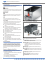
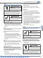
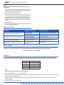
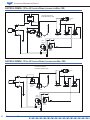
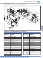
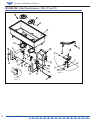
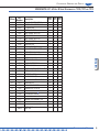
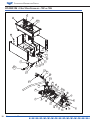
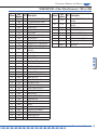
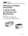
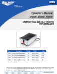
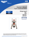
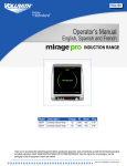
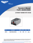
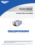
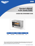
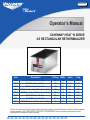
English Operator’s Manual Cayenne® Heat ‘N serve 4/3 Rectangular Rethermalizer Item 72050 72051 72788 72055 72056 72109 72112 72111 Description T43R Countertop without Drain TD43R Countertop with Drain T43R Countertop without Drain T43R Countertop without Drain (Canada Only) TD43R Countertop with Drain (Canada Only) TD43R DI Drop-In with Drain TD43R DI Drop-In with Drain TD43R DI Drop-In with Drain (Canada Only) Voltage Watts 120 1600 120 1600 120 1600 120 1600 120 1600 120 1600 240 1600 120 1600 Amps 13.3 13.3 13.3 13.3 13.3 13.3 7.7 7.7 Plug 5-15P 5-15P 5-15P 5-20P 5-20P 5-15P 6-20P 5-20P Thank you for purchasing this Vollrath equipment. Before operating the equipment, read and familiarize yourself with the following operating and safety instructions. SAVE THESE INSTRUCTIONS FOR FUTURE REFERENCE. Save the original box and packaging. Use this packaging to ship the equipment if repairs are needed. Item No. 2350109-1 Rev 04/11 Countertop Warming and Display Safety Precautions Features and Controls To ensure safe operation, read the following statements and understand their meaning. Please read carefully. F WARNING Warning is used to indicate the presence of a hazard that can cause severe personal injury, death, or substantial property damage if the warning is ignored. CAUTION C Caution is used to indicate the presence of a hazard that will or can cause minor personal injury or property damage if the caution is ignored. A NOTE B Note is used to notify people of installation, operation, or maintenance information that is important but not hazard-related. For Your Safety! These precautions should be followed at all times. Failure to follow these precautions could result in injury to yourself and others. To reduce risk of injury or damage to the equipment: Use only grounded electrical outlets matching the nameplate rated voltage. Use equipment in a flat, level position. Do not use an extension cord with this equipment. Do not plug this equipment into a power strip or multi-outlet power cord. Unplug equipment, turn off and let it cool before cleaning or moving. Unplug equipment when not in use. Do not operate without water. Do not spray controls or outside of equipment with liquids or cleaning agents. Do not clean equipment with steel wool. Keep equipment and power cord away from open flames, electric burners or excessive heat. Do not operate unattended. Do not operate equipment in public areas and/or around children. Do not operate if equipment has been damaged or is malfunctioning in any way. Function and Purpose This equipment is intended to rethermalize containers of refrigerated, previously cooked food and hold containers of hot food at safe serving temperatures. This equipment is not intended or designed to cook raw food product. Before using this equipment it must be cleaned and dried thoroughly. This equipment is not intended for household, industrial or laboratory use. Unpacking the Equipment and Initial Setup When no longer needed, dispose of all packaging and materials in an environmentally responsible manner. 1. Remove all packing material and tape, as well as any protective plastic from the equipment. 2. Clean any glue residue left over from the plastic or tape. 3. Place the equipment in the desired location. 4. For installation of drop-in units see Appendix A. 2 Operator’s Manual D E Figure 1. Features and Controls for Countertop Model. F G G C G D E B Figure 2. Features and Controls for Drop-In Models. A ON/OFF SWITCH. Switches the equipment power ON or OFF. A light illuminates when the equipment power is on. B HEAT CONTROL. Used to set or adjust the temperature of the well. The higher the number the higher the temperature, the lower the number the lower the temperature. On drop-in models this is also the ON/OFF switch. C POWER LIGHT. Illuminates when power is switched on to the unit. D LOW WATER LIGHT. Illuminates when the well needs water added. If the light illuminates during operation, clean fresh water must be added to the well. E DRAIN VALVE (some models). Used to drain water from the well. F WATER LEVEL MARKS. Indicates the correct water level. G THUMBSCREWS. Used to secure the unit to the counter. Countertop Warming and Display Operation WARNING Electrical Shock Hazard. Keep water and other liquids from entering the inside of the unit. Liquid inside the unit could cause an electrical shock. Do not damaged power cord. Do not over fill wells, pans or trays. Liquid could contact the electrical components and cause a short circuit or an electrical shock. Unplug unit before performing service, draining or removing spillage pans and trays. Do not spray water or cleaning products. Do not use a power cord that has been modified or damaged. WARNING Burn Hazard. Do not touch hot food, liquid or heating surfaces while equipment is heating or operating. Hot surfaces, steam and food can burn skin. Allow the hot surfaces to cool before handling. Do not drop or spill water onto the cooking surface as it can spray or splatter. NOTE: If using fractional size pans, adapter bars must be used to keep steam from escaping from between pans. Rethermalizing refrigerated food that has been previously cooked: 1. Preheat the water in the wells by covering wells with empty food containers or covers, and then turning the unit ON and setting the heat control (B) to the maximum heat setting. Preheat for 15 minutes. 2. Place covered container(s) of chilled food product to be rethermalized into equipment. See food safety precautionary note. 3. During the rethermalization process, monitor food temperatures closely for food safety. NOTE: To reach the required safe food temperature as quickly as possible, do not add water or remove food pan during the rethermalization process. 4. Reduce heat setting to a level that will maintain a safe holding temperature and maintain food quality. See food safety precautionary note. Food Safety Precautionary Note: Monitor food temperature closely for food safety. The United States Public Health Service recommends that hot food be held at a minimum of 140 ºF (60 ºC) to help prevent bacteria growth. Maintain correct water level and temperature setting. Periodically remove food container and check the water level. Add water if needed. Hot Food Holding: 1. Preheat the water in the wells by covering wells with empty food containers or covers, and then turning the unit ON and setting the heat During operation: 4. Maintain water level at or near water level mark. Periodically (approximately 2 hours) remove the container of food and check the water level. Add hot water if needed. Some models are equipped with a low water indicator light (B) that illuminates when the water level is low. When finished using the equipment: 1. Turn the heat control (B) to lowest setting, turn the power switch (A) to the OFF position and unplug unit. When removing hot food containers from unit use gloves, mitts or pot holders to protect hands. 2. Allow the unit and water to cool completely. 3. Place a suitable container directly under the drain valve (E) or over a floor drain. Turn the open/close lever to the open position monitoring the flow of liquid going into the container. Use caution to avoid spills that may create a slippery condition. Turn open/close lever to the closed position before the container is full. Dispose of the drained water. Repeat this procedure if necessary. 4. Follow the CLEANING section of this manual. Cleaning To maintain the appearance and increase the service life, clean your equipment daily. English 1. Fill the well to the correct level water mark (F) with clean fresh water. Correct level is about 1” (2.5 CM) of water. Do not over fill. See Figure 1. 2. Plug electrical power cord into a grounded outlet matching the nameplate rated voltage. control (B) to the maximum heat setting. Preheat for 15 minutes. 2. Place container of hot food product, above 140 °F (60 °C), into preheated equipment. 3. Reduce heat setting to a level that will maintain a safe holding temperature and maintain food quality. See food safety precautionary note. WARNING Burn Hazard. Do not touch hot food, liquid or heating surfaces while equipment is heating or operating. Hot surfaces, steam and food can burn skin. Allow the hot surfaces to cool before handling. Do not drop or spill water into the cooking surface as it can spray or splatter. NOTE: Do not use caustic cleaning chemicals, steel wool or commercial lime removal products to clean the equipment. Thoroughly rinse equipment with water after cleaning. 1. Unplug the equipment. 2. Allow the equipment to cool completely before cleaning. WARNING Electrical Shock Hazard. Keep water and other liquids from entering the inside of the unit. Liquid inside the unit could cause an electrical shock. Do not damaged power cord. Do not over fill wells, pans or trays. Liquid could contact the electrical components and cause a short circuit or an electrical shock. Unplug unit before performing service, draining or removing spillage pans and trays. Do not spray water or cleaning products. Do not use a power cord that has been modified or damaged. Operator’s Manual 3 Countertop Warming and Display NOTE: Do not immerse the cord, plug or equipment in water or any other liquid. 1. Turn the heat control (B) to lowest setting, turn the power switch (A) to the OFF position and unplug unit. When removing hot food containers from unit use gloves, mitts or pot holders to protect hands. 2. Allow the unit and water to cool completely. 3. Place a suitable container directly under the drain valve (E) or over a floor drain. Turn the open/close lever to the open position monitoring the flow of liquid going into the container. Use caution to avoid spills that may create a slippery condition. Turn open/close lever to the closed position before the container is full. Dispose of the drained water. Repeat this procedure if necessary. 4. Dispose of the water. 5. Using a damp cloth, sponge dipped in soapy water to clean the inside of the well and the outside of the equipment. Troubleshooting Chart Problem It might be caused by Course of Action Low water in the well. Add hot water to the well to bring to correct level. Pilot light malfunction. Replace pilot light. Heating element malfunction. Replace heating element. Thermostat control malfunction. Replace thermostat control. The equipment does not get hot enough. Too much water in the well. Reduce water amount to the correct level. The equipment runs out of water in a short time. Not using adapter bars with partial size or special shaped pans. Use adapter bars. Low Water Light (some models) illuminates. The ON/OFF light comes on, equipment does not heat. Service and Repair There are no user serviceable parts within this appliance. To avoid serious injury or damage, never attempt to repair the equipment or replace a damaged power cord yourself. Do not send equipment directly to the Vollrath Company. Please contact the qualified professional repair service listed below. Vollrath Technical Service • 1-800-628-0832 Appendix A Have the unit installed only by qualified service personnel. The cutout opening in counter must be in accordance with the chart below. All openings must be within 1/8” of the stated dimension. Use the watertight gasket provided to seal between counter and unit to prevent water from leaking into control areas. Model/Size 72109 72112 72111 Control Box Cut-out Opening, in. (cm) 13-1/4 x 27-1/2 (33.6 x 69.8) 13-1/4 x 27-1/2 (33.6 x 69.8) 13-1/4 x 27-1/2 (33.6 x 69.8) 5-7/8 x 6-3/8 (16.1 x 14.9) NOTE All cutout openings must be within 1/8” of listed opening sizes. 1. Place the watertight gasket over the cut-out and center the well. 2. Tighten the thumbscrews (G) slowly and in an alternating pattern to evenly compress the gasket. See Figure 1. The gasket should create a 1/8” (3 mm) gap between the well and the mounting surface. 3. Plug the equipment into a properly grounded electrical supply matching the nameplate rating. Damage to the equipment can occur if incorrect power is supplied to equipment. 4. Follow the OPERATION section of this manual. 4 Operator’s Manual Countertop Warming and Display ELECTRICAL DRAWING - 120 Volt 4/3 Drop-In Warmer 120 Volt 3/4 Drop-In Warmer Wire Diagram WARMER SIDE CONTROL SIDE 120 Volt 120 Volt LOW WATER LIGHT HEAT ON LIGHT GREEN - LOOSE WARMER COVER PANEL GROUND ORANGE WHITE WHITE GREEN - LOOSE UNIVERSAL THERMOSTAT BRACKET (UTB) GROUND LEFT HEATER UTB RIGHT HEATER GREEN WARMER COVER PANEL GROUND POWER CORD SET WHITE LOW WATER THERMOSTAT # 10-32 GROUND GREEN BLACK LOW WATER LIGHT LOW WATER LIGHT DRAIN SIDE HEATER #10 RING BLACK WHITE ORANGE BLACK LEFT HEATER (SIDE OPPOSITE DRAIN) HIGH LIMIT 17950 THERMOSTAT ORANGE BLACK HEAT ON LIGHT LOW WATER THERMOSTAT ORANGE BLACK WHITE LOOSE HEATER #10 RING RIGHT RIGHT HEATER (DRAIN SIDE) HIGH LIMIT HEATER #10 RING LEFT English ELECTRICAL DRAWING - 208-240 Volt 4/3 Drop-In Warmer 240 Volt 3/4 Drop-In Warmer Wire Diagram WARMER SIDE CONTROL SIDE 208-240 Volt 208-240 Volt LOW WATER LIGHT POWER ON SWITCH HEAT ON LIGHT # 10-32 GROUND HEAT ON LIGHT AND WATER LIGHT THERMOSTAT #2 TERMINAL POWER ON SWITCH WARMER COVER PANEL GROUND ORANGE WHITE WHITE GREEN - LOOSE GREEN - LOOSE UNIVERSAL THERMOSTAT BRACKET (UTB) GROUND LEFT HEATER UTB RIGHT HEATER GREEN WARMER COVER PANEL GROUND LOW WATER THERMOSTAT GREEN BLACK BLACK DRAIN SIDE HEATER #10 RING BLACK WHITE ORANGE ORANGE THERMOSTAT #1 TERMINAL BLACK LOOSE HEATER #10 RING RIGHT LOW WATER THERMOSTAT LEFT HEATER (SIDE OPPOSITE DRAIN) HIGH LIMIT THERMOSTAT WHITE LOOSE RIGHT HEATER (DRAIN SIDE) HIGH LIMIT Operator’s Manual 5 Countertop Warming and Display ELECTRICAL DRAWING - 120 Volt 4/3 Countertop Warmer, (units made after March 1999) 120 Volt 4/3 Warmer Units After March 1999 Low Water Light Dual Pole Rocker Switch L G N Power Light High Limit Switch High Limit Switch High Limit Switch Thermostat Heater Element Heater Element ELECTRICAL DRAWING - 120 Volt 4/3 Countertop Warmer, (units made before March 1999) 120 Volt 4/3 Warmer Units Before March 1999 Low Water Light L G N Lighted Three Pole Switch High Limit Switch Thermostat Heater Element Heater Element 6 Operator’s Manual High Limit Switch High Limit Switch Countertop Warming and Display EXPLODED VIEW - 4/3 Heat ‘N Serve Rethermalizer ~ 72050 and 72055 3 1 2 6 7 8 3 4 8 2 5 8 5 7 4 1 15 10 8 3 27 16 11 28 18 9 12 11 19 26 7 17 23 29 21 English 25 10 3 22 24 SPAR PARTS LIST - 4/3 Heat ‘N Serve Rethermalizer ~ 72050 and 72055 Part Description Callout Number 1 17755 WELL, 4/3's PLASTIC 2 17868 3 Part Description Callout Number 17 17686 "D" SHAPED HEATER GASKET 18 1755901 44287 HEATER, 120V 800W 19 17388 KNOB, CONTROL 4 44459 HI LIMIT PLATE 20 17848 HARNESS, WIRE (NOT SHOWN) 5 17504 THERMOSTAT, HIGH LIMIT 21 44292 PANEL, BOTTOM 6 17741 LOOP CLAMP 22 17416 LEG, PHENOLIC (BLACK) 7 17020 SCREW #6-32 x 1/2" PH RD 23 17018 SCREW, 8-32 X .500 8 17019 #6-32 KEPS NUT 24 21775 #8-32 TRUSS HEAD .500 LG. 9 25438 THERMOSTAT - REGULATING 25 17023 CORD, POWER, 120V 5-15P 10 17117 SCREW 10-32 x 1/4" PHILLIPS 25 17860 CORD, POWER, 120V 5-20P (Canada Only) 11 17014 SCREW, #10-32 X .625 THREAD ROLLING 26 17872 90 DEG STRAIN RELIEF 12 44293 PANEL, SIDE 27 23989 CLAMP, LOOP, 3/8 DIA X 1/2 13 44297 PANEL, BACK 28 17559 PILOT LIGHT, RED - 120V 14 44295 PANEL, FRONT 29 2325401 15 23095 Rivet, Pop - .125 Dia. 16 17074 THERMOSTAT, SHORT CAPILLARY 29292-2 SCREW, M4-0.7 X 5MM PILOT LIGHT, BLUE - 120V SWITCH, ROCKER, 125V SWITCH KIT, For models made before March 1999 Operator’s Manual 7 Countertop Warming and Display EXPLODED VIEW - 4/3 Heat ‘N Serve Rethermalizer ~ 72109, 72111 and 72112 17 4 17 1 9 21 3 27 13 16 A B 18 19 22 15 14 20 23 24 7 23 26 8 10 13 DETAIL B SCALE 1 : 3 Operator’s Manual 12 12 6 8 5 DETAIL A SCALE 1 : 2 Countertop Warming and Display SPARE PARTS LIST - 4/3 Heat ‘N Serve Rethermalizer ~ 72109, 72111 and 72112 Callout 1 2 3 Part Description Number Model Model Model 72109 72112 72111 17800 44138 44024 WELL, 4/3's PLASTIC, W/DRAIN CONTROL BOX ASSEMBLY, 240V BOTTOM COVER 1 1 1 1 1 1 4 44287 HEATER, 120V 800W 2 2 2 5 17847 CORD, POWER, 120V 5-15P 1 5 17860 CORD, POWER, 120V 5-20P 5 17739 CORD, POWER, 240V 6-15P 6 26543 CORD CONNECTOR 1 1 1 7 8 9 44196 23424 17868 DRAIN ADAPTER DRAIN VALVE ASSEMBLY "D" SHAPED HEATER GASKET 1 1 2 1 1 2 1 1 2 10 17950 THERMOSTAT, HIGH LIMIT 2 2 2 11 25438 THERMOSTAT - REGULATING 1 1 1 12 17496 SCREW, #6-32 X .250 6 6 6 13 17014 SCREW, #10-32 X .625 9 9 9 14 17365 O-RING, ADAPTER, DRAIN 1 1 1 15 17018 SCREW, 8-32 X .500 6 6 6 16 17928 UNIVERSAL THERMOSTAT BRACKET 2 2 2 17 17117 SCREW, #10-32 X .25 LG. 2 2 2 18 23686 RIVET, POP - .125 DIA. 4 4 4 19 44005 MOUNTING BRACKET 1 1 1 20 44001 MOUNTING BRACKET W/CUTOUT 1 1 1 21 44179 MOUNTING CLIP 4 4 4 22 23035 1/4-20 x 2" THUMB SCREW 4 4 4 23 17020 SCREW #6-32 x 1/2" PH RD 1 1 1 24 17019 17019 #6-32 KEPS NUT 2 2 2 25 17083 SLEEVING (NOT SHOWN) 1 1 1 26 17428 RATING LABEL - NSF 1 1 1 27 44137 CONTROL BOX ASSEMBLY, 120V 1 1 17972 HARNESS ASSEMBLY (120V) 1 1 17973 HARNESS ASSEMBLY (240V) SWITCH KIT, For models made before March 1999 1 1 English 29292-2 1 1 1 1 1 Operator’s Manual 9 Countertop Warming and Display EXPLODED VIEW - 4/3 Heat ‘N Serve Rethermalizer ~ 72051 and 72056 3 1 2 3 2 16 28 17 18 19 42 20 27 26 45 33 22 24 23 43 33 25 34 43 31 32 30 7 12 29 6 8 4 8 5 5 7 11 1 8 4 8 3 12 10 9 10 Operator’s Manual 12 11 3 7 Countertop Warming and Display SPARE PARTS LIST - 4/3 Heat ‘N Serve Rethermalizer ~ 72051 and 72056 Callout Part QTY Description Number Callout Part QTY Description Number 17875 1 HEATER, 120V 800W 39 17106 1 2 HI LIMIT PLATE 17504 2 THERMOSTAT, HIGH LIMIT 40 17856 1 OSI - 4/3 THERMOSET WELL (NOT SHOWN) DC 732 RTV SEALANT, CLEAR (NOT SHOWN) PRODUCT LABEL 6 17741 1 LOOP CLAMP 41 17559 1 PILOT LIGHT, RED - 120V 7 17020 9 SCREW #6-32 x 1/2" PH RD 42 2325401 1 SWITCH, ROCKER, 125V 8 17019 10 #6-32 KEPS NUT 43 23408 1 TUBING, 1/2" ID SILICONE 23.0" 9 25438 1 THERMOSTAT - REGULATING 44 26883 2 CLAMP-HOSE 7/8" OD TUBING 10 17496 2 SCREW 6-32 x 1/4" THREAD/FORM 45 17860 1 11 17117 2 12 17014 9 13 44293 2 SCREW 10-32 x 1/4" PHILLIPS SCREW, #10-32 X .625 THREAD ROLLING PANEL, SIDE Cord, Power, 120V 5-20P (Canada Unit) SWITCH KIT, For models made before March 1999 14 44299 1 PANEL, BACK 15 44286 1 PANEL, FRONT 16 23095 12 Rivet, Pop - .125 Dia. 17 17074 1 THERMOSTAT, SHORT CAPILLARY 18 17686 2 SCREW, M4-0.7 X 5MM 19 1755901 1 PILOT LIGHT, BLUE - 120V 20 17388 1 KNOB, CONTROL 21 17848 1 HARNESS, WIRE (NOT SHOWN) 22 44303 1 PANEL, BOTTOM 23 17416 4 LEG, PHENOLIC (BLACK) 24 17018 14 SCREW, 8-32 X .500 25 21775 12 #8-32 TRUSS HEAD .500 LG. 26 17847 1 CORD, POWER, 120V 5-15P 27 17872 1 90 DEG STRAIN RELIEF 28 44288 2 WELL SPACER 29 17365 1 O-RING, ADAPTER, DRAIN 30 43388 1 DRAIN ADAPTER 31 23403 1 ELBOW, 3/4 NPT X 1/2 BARB 32 Default 1 FAUCET 33 23619 1 3/8 NPT Straight Pipe Coupling 34 23413 1 3/8 Pipe to 1/2 Tube Adapter 35 17865 1 LABEL - RATING 36 17428 1 RATING LABEL - NSF 37 17858 1 LABEL, CONTROL 17800 1 WELL, 4/3's PLASTIC, W/DRAIN 2 17868 2 "D" SHAPED HEATER GASKET 3 44287 2 4 44459 5 29292-2 English 38 1 Operator’s Manual 11 Countertop Warming and Display Warranty Statement for The Vollrath Co. L.L.C. The Vollrath Company LLC warrants the products it manufactures and distributes against defects in materials and workmanship for a period of one year, except as specifically provided below. The warranty runs 12 months from the date of original installation. (End user receipt) 1. 2. 3. 4. Refrigeration compressors – The warranty period is 5 years. Replacement parts – The warranty period is 90 days. Fry pans and coated cookware – The warranty period is 90 days EverTite™ Riveting System – The warranty covers loose rivets only, forever. 5. Cayenne® Heat Strips – The warranty period is 1 year plus an additional 1 year period on heating element parts only. 6. Ultra and Professional Induction Ranges – The warranty period is 2 years. 7. Mirage and Commercial Induction ranges - The warranty period is 1 year. 8. ServeWell® Induction Workstations – The warranty period is one year on the workstation table and 2 years on induction hobs. 9. Slicers – The warranty period is 10 years on gears and 5 years on belts. 10.Mixers – The warranty period is 2 years. 11. Extended warranties are available at the time of sale. 12.Boxer Mixers – 1 Year exchange Warranty. 13.Vollrath – Redco products – The warranty period is 2 years. 14.Optio / Arkadia product lines – The warranty period is 90 days. 15.All non-stick products (i.e. fry pans and surfaces) are 90 days for the non stick surfaces. All products in the Jacob’s Pride® collection, including the following, have a lifetime warranty: • NSF Certified One-Piece Dishers • NSF Certified Spoodle® Utensils • NSF Certified Heavy-Duty Spoons with Ergonomic Handle • NSF Certified Heavy-Duty Basting Spoons • Heavy duty Turners with Ergonomic handle • One-Piece Tongs* • Heavy-Duty One-Piece Ladles* • Nylon Handle Whips • One-Piece Skimmers • Tribute®, Intrigue®, and Classic Select® Cookware* Items sold having no warranty: • Meat Grinder Knives • Light Bulbs in Convection Ovens and Hot Food Merchandiser • Oven Door Seals • Oven Door Glass • Hot Food Merchandisers / Display Case Glass • Calibration and set up of gas equipment • Slicer / Dicer blades (table top food prep) – Redco and Vollrath *Jacob’s Pride® warranty does not cover Kool-Touch®, non stick coatings and silicone handles. THIS WARRANTY IS IN LIEU OF ANY OTHER WARRANTIES, EXPRESS OR IMPLIED, INCLUDING ANY IMPLIED WARRANTY OF MERCHANTABILITY OR FITNESS FOR A PARTICULAR PURPOSE As The Vollrath Company LLC’s only responsibility and the purchaser’s only remedy, for any breach of warranty, The Vollrath Company LLC will repair or, at its option, replace the defective product or part without charge, except as otherwise provided below: • For refrigeration compressors and the second year of the warranty on Cayenne® Heat Strips and mixers, The Vollrath Company LLC will provide the repaired or replacement part only; and the buyer will be responsible for all labor charges incurred in performing the repair or replacement. • To obtain warranty service, the buyer will be responsible to return to The Vollrath Company LLC any product (other than gas equipment that is permanently installed) weighing less than 110 lbs. or located outside of a 50-mile radius of a certified technician designated by The Vollrath Company LLC to perform warranty repairs. If a Vollrath Technician cannot be contacted check the website for service contact points. (Please refer to the Product Catalogue for weights and sizes of product) • No remedy will be available for products that have been damaged by accident, carelessness, improper installation, lack of proper setup or supervision when required, neglect, improper use, installation or operation contrary to installation and operating instructions or other causes not arising out of defects in materials or workmanship. At the buyer’s request, The Vollrath Company LLC will repair and or replace such products at a reasonable cost. • No remedy will be available for slicers where blade has not been sharpened (Refer to owner’s manual for sharpening instructions) • No remedy will be available for mixers damaged by changing gears while unit is running or overloading, in either case as determined by a Vollrath Certified Technician • Warranty work must be authorized in advance by The Vollrath Company LLC. See the operating and safety instructions for each product for detailed warranty claim procedures. • No remedy will be available for product returned and found to be acceptable to the product specification. • No remedy will be available under any warranty not registered as required below. LIMITATION OF LIABILITY: THE VOLLRATH COMPANY LLC SHALL HAVE NO LIABILITY FOR INCIDENTAL OR CONSEQUENTIAL DAMAGES OF ANY KIND, WHETHER BASED UPON NEGLIGENCE OR OTHER TORT, BREACH OF WARRANTY, OR ANY OTHER THEORY. 12 Operator’s Manual Warranty Procedure On all warranty calls, the following process and information is required: • • • • • • • All warranty claims will start with a call to Vollrath Technical Service support line.(800-354-1970). A technical support professional will work to diagnose the issues, and provide the details for the service solution. Name and phone number of person calling Business name, street address, city, state and zip Model and serial number Date of purchase and proof of purchase (Receipt) Name of dealer where unit was purchased NOTE: Vollrath will not accept products sent without the proper procedure being followed. Important: TO MAKE A CLAIM FOR ANY REMEDY UNDER THIS WARRANTY, YOU MUST REGISTER YOUR WARRANTY. Register Today ONLINE: Register your warranty on-line now at www.Vollrathco.com NO WEB ACCESS: If you do not have access to the web, kindly register by completing the warranty registration form and faxing it to The Vollrath Co. LLC office in the country of purchase. Warranty Registration Business Name Key Contact Name Email Street Address City State Country Phone Fax Model Serial Number Zip Code Item Number - - Operation Type RR Limited Service Restaurant RR Full Service Restaurant RR Convenience Store RR Recreation RR Business/Industry RR Primary/Secondary School RR Long-Term Care RR Senior Living Reason for Selecting Our Product RR Appearance RR Full Service Restaurant RR Ease of Operation RR Versatility of Use RR Bars and Taverns RR Hotel/Lodging RR Colleges/University RR Military RR Supermarket RR Airlines RR Hospitals RR Corrections RR Availability RR Price RR Sellers Recommendation RR Brand Would You Like to Receive Our Full-Line Catalog and Remain on Our Mailing List? The Vollrath Company, L.L.C. 1236 North 18th Street Sheboygan, WI 53081-3201 U.S.A. www.vollrathco.com Main Tel: 800.628.0830 Fax: 800.752.5620 RR Yes RR No Technical Services: 800.628.0832 Service Fax: 920.459.5462 Canada Service: 800.695.8560 © 2010 The Vollrath Company, L.L.C.