1
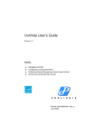
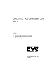
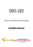
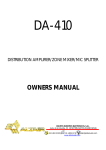
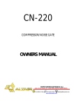
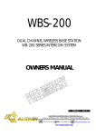
EF-200
DUAL CHANNEL MASTER STATION
E-200 SERIES INTERCOM SYSTEM
OWNERS MANUAL
AUDIO ELECTRONICS DESIGN
EQUIPOS EUROPEOS ELECTRÓNICOS, S.A.L
Avda. de la Industria, 50. 28760 TRES CANTOS-MADRID (SPAIN).
34-91-761 65 80
34-91-804 43 58
www.altairaudio.com
[email protected]
E-200 SERIES INTERCOM SYSTEM — EF-200 DUAL CHANNEL MASTER STATION
2
1. INTRODUCTION.................................................................................................................................................................................. 3
2. SWITCHES, CONTROLS, ADJUSTMENTS AND CONNECTORS.................................................................................................... 4
FRONT PANEL ................................................................................................................................................................................... 4
REAR PANEL ...................................................................................................................................................................................... 5
3. WORKING PRECAUTIONS................................................................................................................................................................ 6
4. INSTALLATION ................................................................................................................................................................................... 6
UNPACKING ..................................................................................................................................................................................... 6
MOUNTING....................................................................................................................................................................................... 6
CHANGING THE FUSE ..................................................................................................................................................................... 6
CONNECTING TO THE MAINS........................................................................................................................................................ 7
EMERGENCY BATTERY PLACEMENT .............................................................................................................................................. 7
PROGRAM INPUT CONNECTION................................................................................................................................................... 7
UNBALANCED INPUT:.................................................................................................................................................................. 8
BALANCED INPUT: ....................................................................................................................................................................... 9
PA OUTPUT CONNECTION ............................................................................................................................................................. 9
UNBALANCED OUTPUT:.............................................................................................................................................................10
BALANCED INPUT: ...................................................................................................................................................................... 11
PA OUTPUT RELAY CONNECTION ................................................................................................................................................ 11
EXTERNAL UNITS CONNECTION ...................................................................................................................................................12
MULTICHANNEL SYSTEM CONNECTION (MASTER-SLAVE).......................................................................................................13
CONNECTION OF INTERCOM SYSTEMS WITH MORE THAN 50 BELTPACKS.........................................................................15
5. OPERATION .......................................................................................................................................................................................15
HEADSET CONNECTION.................................................................................................................................................................15
HEADSET VOLUME CONTROL .......................................................................................................................................................16
PA-MIC OUTPUT + RELAY CONTROL SWITCH ...........................................................................................................................16
BUZZER ON/OFF SWITCH..............................................................................................................................................................16
REMOTE MUTE ALL MICS AND BUZZER SWITCHES ..................................................................................................................17
CALL SWITCH...................................................................................................................................................................................17
MIC ON/OFF/PUSH TO TALK SWITCH.........................................................................................................................................17
SIDETONE CONTROL.......................................................................................................................................................................18
LINE A AND B LISTEN BALANCE CONTROL .................................................................................................................................18
PROGRAM INPUT LEVEL CONTROL..............................................................................................................................................18
PROGRAM SENDING TO LINES A/B SWITCHES .........................................................................................................................18
PROGRAM TO HEADPHONES CONTROL ....................................................................................................................................18
LINES A AND B LINK SWITCH........................................................................................................................................................18
SLAVE CHANNELS LINK SWITCH ..................................................................................................................................................19
EMERGENCY SWITCH (BATTERY OPERATION) ............................................................................................................................19
6. OPTIONS............................................................................................................................................................................................19
PROGRAM INPUT TRANSFORMER (IT-DA) ..................................................................................................................................19
PA OUTPUT TRANSFORMER (OT-DA) ..........................................................................................................................................19
SECURITY COVER (TP-1)..................................................................................................................................................................19
KEY LOCKED SECURITY COVER (TS-1) ..........................................................................................................................................19
7. SPECIAL OPERATIONS.....................................................................................................................................................................20
PROGRAM INPUT TRANSFORMER (IT-DA) .................................................................................................................................20
OUTPUT TRANSFORMER (OT-DA)................................................................................................................................................20
OPENING THE INTERCOM LINE TERMINAL IMPEDANCE...........................................................................................................21
CHANGING THE MIC GAIN ...........................................................................................................................................................21
PA OUTPUT CONFIGURATION......................................................................................................................................................21
ACTIVATING THE MICROPHONE PHANTOM POWER ..............................................................................................................22
PROGRAM INPUT CONFIGURATION IN A MULTICHANNEL SYSTEM (MASTER-SLAVE) ......................................................22
CHANGING THE BUZZER LEVEL...................................................................................................................................................23
PROGRAM INTERRUPT WITH THE PA-MIC SWITCH CONFIGURATION.................................................................................23
CONFIGURATION OF THE MULTIPURPOSE RELAY ACTIVATION ............................................................................................23
PROGRAM INTERRUPT WITH THE MIC SWITCHES CONFIGURATION ...................................................................................24
8. BLOCK DIAGRAM AND HOW IT WORKS.....................................................................................................................................25
9. REPAIR GUIDE .................................................................................................................................................................................. 27
10. APPLICATION EXAMPLE................................................................................................................................................................28
11. TECHNICAL SPECIFICATIONS ........................................................................................................................................................29
12. WARRANTY.....................................................................................................................................................................................30
E-200 SERIES INTERCOM SYSTEM — EF-200 DUAL CHANNEL MASTER STATION
3
1. INTRODUCTION
Congratulations on your purchase of the ALTAIR dual channel master station EF-200 of the
E-200 series intercom system. There is a lot the characteristics that make of the ALTAIR E-200 series
one of the most highlighted in the audio professional market, some are enumerated here:
The new ALTAIR E-200 SERIES add more features to our popular Espiral E-100 series, maintaining
compatibility. All the components in the system incorporate a microcontroller to implement different
tasks as Mic Killer, Remote all Buzzer switch-off, Mic Switch Latch or Push To Talk, Program Interrupt,
etc.
Remote All Mic switch-off helps the operator to maintain a lower noise conversation in noisy
environments. Also implemented is the remote All Buzzers switch-off feature to avoid undesired
audible CALL signalling during performances.
The Master Station unit powers all the System components and incorporates new special features
as System Expandability or Battery Operation.
System Expandability permits creating a multichannel (4, 6, or more channels) Intercom System by
using more Master Stations in a daisy chain arrangement. This feature enables freedom in the System
design and in-site future upgrades. Rental companies can benefit with lower component inventories.
Our new internal Battery operation permits short-time communications in difficult situations (= no
Power) of emergency.
The ALTAIR EF-200 unit incorporates an internal worldwide voltage operation power supply that
powers all the system. In case of a short circuit on any point of the line, the unit shuts down with
automatic and instantaneous reset.
Before beginning it is important to read this manual. This manual will help you to install and use
your new intercom master station. It is very important to read it carefully, mainly the paragraphs
marked as NOTE, PRECAUTION and DANGER, for your security.
Save the original packing, you can re-use it to transport the unit. NEVER SHIP THE ALTAIR EF-200
WITHOUT ITS ORIGINAL PACKING.
E-200 SERIES INTERCOM SYSTEM — EF-200 DUAL CHANNEL MASTER STATION
2. SWITCHES, CONTROLS, ADJUSTMENTS AND CONNECTORS
These are the switches, controls, adjustments and connectors that you can find in your ALTAIR intercom master station. The description and
explanation of each one will be found in the corresponding section.
FRONT PANEL
CALL SWITCH.
HEADSET CONNECTOR.
MIC ON/OFF/PUSH TO TALK SWITCH.
SIDETONE CONTROL.
HEADSET VOLUME CONTROL.
LINE A AND B LISTEN BALANCE CONTROL.
PA-MIC OUTPUT + RELAY CONTROL SWITCH.
PROGRAM INPUT LEVEL CONTROL.
BUZZER ON/OFF SWITCH.
PROGRAM SENDING TO LINES A/B SWITCHES.
REMOTE MUTE ALL MICS AND BUZZER SWITCHES.
PROGRAM TO HEADPHONES CONTROL.
4
E-200 SERIES INTERCOM SYSTEM — EF-200 DUAL CHANNEL MASTER STATION
LINES A AND B LINK SWITCH.
EMERGENCY SWITCH (BATTERY OPERATION).
SLAVE CHANNELS LINK SWITCH.
POWER SWITCH.
REAR PANEL
MAINS CONNECTOR AND FUSEHOLDER.
PA OUTPUT CONNECTOR XLR-3-32.
BATTERY HOLDER.
PA OUTPUT RELAY CONNECTOR JACK ¼”.
PROGRAM INPUT MIC/LINE SELECTOR SWITCH.
INTERCOM LINE CONNECTORS XLR-3-31 AND
XLR-3-32.
PROGRAM INPUT CONNECTOR XLR-3-31.
MULTICHANNEL LINKS CONNECTORS FCC-68.
5
E-200 SERIES INTERCOM SYSTEM — EF-200 DUAL CHANNEL MASTER STATION
6
3. WORKING PRECAUTIONS
The manufacturer is not responsible of any damage that can possibly happen to the intercom
master station outside the limits of the warranty or those produced by not taking care with the
working precautions.
Mains voltage must be between the limits of the admitted power supply (90-264 VAC, 5060 Hz) and that the fuse must be the appropriate (2A slow blow type: T2A). Damage caused
by connection to improper AC voltage is not covered by any warranty.
DANGER: Inside the unit there are high voltages, do not open it. The unit does not
contain elements that could be repaired by the user. Whenever the intercom master
station is connected to the mains, it carries elements with high voltages. In order to
disconnect the unit completely, you must disconnect it from the mains.
CAUTION: Protect the unit from the rain and moisture. Ensure that no objects or liquids enter it. If
liquid is spilled into the unit, disconnect it from the mains and consult a qualified service technician.
Do not place the unit close to heat sources.
4. INSTALLATION
UNPACKING
Before leaving the factory, each intercom master station has been carefully inspected and
tested. Unpack and inspect the unit for any damage that may have occurred during shipment. If
any damage is found, does not connect the unit to the mains; notify the salesperson immediately;
a qualified service technician should inspect the unit.
Save the original packing, you could use if you need to transport the unit. NEVER SHIP THE
INTERCOM MASTER STATION WITHOUT ITS ORIGINAL PACKING.
MOUNTING
It is always recommended to mount the unit in rack, either for mobile or fixed installations, for
protection, safety, aesthetics, etc.
The ALTAIR EF-200 is designed for standard 19" rack mounting, and takes up 1u high rack
space.
CHANGING THE FUSE
This unit incorporates an internal, worldwide voltage operation power supply, and it is
prepared to work from 90 to 264 VAC, 50-60Hz.
Make sure that the unit is disconnected from the mains.
In the unit rear panel are placed the mains connector, the mains selector
and the fuse holder. The box bellow this mains connector is called fuse holder.
Take out the fuse holder.
After extracting the fuse holder, the fuse will appear, take out it and change
for the new one.
Insert the fuse holder into the mains connector again.
7
E-200 SERIES INTERCOM SYSTEM — EF-200 DUAL CHANNEL MASTER STATION
Make sure that the fuse is the right one: 2A slow blow type - T2A
CAUTION: Always make sure after changing the fuse, that it is the right one.
CONNECTING TO THE MAINS
The connection of the intercom master station power supply to the mains takes
place by a standard cord included in the box.
Make sure that the unit power switch is at 0 position (turned off).
Insert the female I.E.C. connector of the tripolar cable into the unit power supply
male connector, placed at the rear panel.
Insert the male connector of the tripolar cable into the mains plug.
Turn on the unit power switch.
will light slightly, indicating that
In that moment the CALL LED
the unit is turned on.
indicator
CAUTION: Make sure that the mains voltage is the correct as well as their fuse is the right one.
EMERGENCY BATTERY PLACEMENT
The central unit has a lodging for a 9VDC battery (6LR61 type) located in the rear panel, that
allows the system operation in no power difficult situations during a short period of time. The use of
alkaline batteries is recommended.
Make sure that the unit power switch is at 0 position (turned
off).
In the unit rear panel is placed the battery holder. Take out
the battery holder, pushing up and toward you with a coin
Insert the battery into the battery holder, taking into account
the polarity that comes indicated inside the battery holder.
Insert the battery holder into its rear panel plastic box.
NOTE: The battery power has an internal fuse, located inside the unit, in order to protect the unit of
excessive currents in the battery. If it is necessary to change the fuse, make sure that the device is
disconnected from the mains, and open the top cover according to the indications of the section
special operations. The fuse is placed in the top right corner, just beside the battery holder. After
changing make sure that it is the adequate T1A (1 ampere, slow blow type).
PROGRAM INPUT CONNECTION
The intercom master station program input signal is carried out through a XLR-3-31 female
connector. The input connection is balanced, with a nominal impedance of 40 KΩ (20 KΩ
E-200 SERIES INTERCOM SYSTEM — EF-200 DUAL CHANNEL MASTER STATION
8
unbalanced). The next list shows the input pins correspondence as A.E.S recommends:
PROGRAM INPUT - XLR-3-31
0V
PIN 1
PIN 2
HOT (+)
COLD (-)
PIN 3
The input connection depends on two factors, the first is the type of input signal balanced or
unbalanced, and the second the ground configuration of the sound source (floating or groundreferenced). The next pictures show some of the different possibilities of connection, relying on the
type of input signal, balanced or unbalanced and according to the ground configuration of the
equipment (floating or ground-referenced).
In the next diagrams, we use the following symbols:
Sound source with mains cord without ground connection.
Sound source with mains cord with ground connection.
Sound source with the EARTH-LINK OFF.
Sound source with the EARTH LINK ON.
UNBALANCED INPUT:
This type of connection will be used when the sound source does not provide balanced
output. If it’s possible it is better using the connection type 1.
1) Using twin-lead shielded cable:
E-200 SERIES INTERCOM SYSTEM — EF-200 DUAL CHANNEL MASTER STATION
9
2) Using single conductor shielded cable:
BALANCED INPUT:
PA OUTPUT CONNECTION
The PA output signal is carried out through a XLR-3-32 male connector. The output is
balanced, with a nominal impedance of 100 Ω. The next list shows the input pins correspondence
as A.E.S recommends:
E-200 SERIES INTERCOM SYSTEM — EF-200 DUAL CHANNEL MASTER STATION
10
PA OUTPUT - XLR-3-32
0V
PIN 1
PIN 2
HOT (+)
COLD (-)
PIN 3
The output connection depends on two factors, the first is the type of input signal balanced or
unbalanced, and the second the ground configuration of the sound destination unit (floating or
ground-referenced). The next pictures show some of the different possibilities of connection,
relying on the type of output signal, balanced or unbalanced and according to the equipment’s
ground configuration (floating or ground-referenced).
In the next diagrams, we use the following symbols:
Sound destination unit with mains cord without ground connection.
Sound destination unit with mains cord with ground connection.
Sound destination unit with the EARTH-LINK OFF.
Sound destination unit with the EARTH LINK ON.
UNBALANCED OUTPUT:
This type of connection will be used when the sound destination unit does not provide a
balanced input. If it’s possible it is better using the connection type 1.
1) Using twin-lead shielded cable:
E-200 SERIES INTERCOM SYSTEM — EF-200 DUAL CHANNEL MASTER STATION
11
2) Using single conductor shielded cable:
BALANCED INPUT:
PA OUTPUT RELAY CONNECTION
The PA output relay connection allows to carry out a control on an external application every
time the PA output is activated (connection with unidirectional transmission systems - radio
stations. Lights turn on/off, motors, etc.).
The multipurpose relay connection takes place with a JACK ¼” connector. The next list shows
the multipurpose relay PIN correspondence with the JACK ¼":
12
E-200 SERIES INTERCOM SYSTEM — EF-200 DUAL CHANNEL MASTER STATION
RELAY
COMMON
NORMALLY CLOSE
NORMALLY OPEN
JACK ¼”
TIP
RING
SLEEVE
TIP.
RING.
SLEEVE.
In the factory configuration, the PA output relay is activated with the PA output switch, but the
multipurpose relay can be configured to be activated upon activating the channel A and/or B
microphone or upon activating the remote mute — buzzers signal. In order to obtain more
information, consult the special operation section.
NOTE: The NORMALLY CLOSE terminal is joined with the COMMON terminal when the PA output is
not activated, and the NORMALLY CLOSE is joined with the COMMON terminal when the PA output
is activated.
EXTERNAL UNITS CONNECTION
The external units connection to the master station is carried
through twin-lead shielded cable and XLR-3-31/XLR-3-32
connectors. Each master station channel provides two XLR-3-31
connectors and a XLR-3-32 connector wired internally in parallel
mode.
The next list shows the signal distribution in the pin XLR
connectors.
XLR-3-31/XLR-3-32 — INTERCOM LINE
GND
PIN 1
PIN 2
+VDC
SIGNAL
PIN 3
Certain rules have to be followed when installing the cables of an intercom system. This is to
avoid ground loops and to minimize the power loss and the possible effect of electromagnetic
fields.
Do not connect the XLR pin 1 to the XLR metal housing or to metal wall boxes to avoid ground
loops. The ground loop could increases notably the system background noise.
Do not close the intercom line connection (avoid closed loops). Each intercom line leaves from
the master station towards the remote stations, but it does not return to the master station. If the
connection is closed, a ground loop with the increase from the system noise will take place.
Use high quality cables and minimize its longitude. The DC resistance of a low quality cable or
very long affects to the power consumption, the channels crosstalk and the system frequency
response.
Place the master station the closest possible to the maximum consumption zone; that is to say
to the zone in which more external units are placed.
The next picture shows the habitual connection of an intercom system formed by four
beltpacks units (two for each channel) and a master station EF-200. In the section APPLICATION
EXAMPLES are shown another type of connections.
E-200 SERIES INTERCOM SYSTEM — EF-200 DUAL CHANNEL MASTER STATION
13
MULTICHANNEL SYSTEM CONNECTION (MASTER-SLAVE)
The MASTER-SLAVE connection of master stations allows to carry out
multichannel systems and use an only headphone for all the intercom lines.
The connection is made with an 8 pin RJ45 cable (of wide use in computer
networks) without inverting (extension). We will introduce in the central unit that
we want to configure as master the cable connector FCC-68 in the master station
connector marked as MASTER, and in the master station we want to configure as
slave the other cable end in the master station connector marked as SLAVE. If we want to configure
more slave units, we will use another 8 pin RJ45 cable and we will connect the cable connector
FCC-68 in the first slave unit, and the other cable end in the connector FCC-68 marked as SLAVE of
the following slave unit, and so forth up to one maximum of 5 master stations, what would give us
a maximum of 10 intercom lines controlled by this system.
The operation in MASTER-SLAVE mode is very simple. That way, we will listen all the intercom
lines in the headset connected to the master station. The volume control of each main station
adjusts the headset level of its local intercom lines (MASTER 1,2- SLAVE Nº1 3,4- SLAVE Nº2 5,6SLAVE Nº3 7,8- SLAVE Nº4 9,10) and the local listen balance control between intercom lines the
channel mix controlled by the main station.
The mic sending to the different intercom lines is carried out with the mic on/off switch of
each intercom line (each main station controls two intercom lines).
The call signal to each intercom line is carried out with of the CALL switch associate, as well
as each received call is shown in their associate channel (the associated led starts blinking and if
the buzzer is activated, the unit emits an intermittent sound). The buzzer on/off switch is controlled
by each main station, as well as the remote mutes of all mics and buzzers.
In multichannel operation, it is possible to enable/disable the microphones of all the stations
(master or slaves), as the remote mute buzzers function of all the stations and carry out a call to all
the system intercom lines (in order to obtain more information consult the section — BUZZER
ON/OFF SWITCH).
The program input corresponding to the main station configured as MASTER will work alone
(each main station can be configured so that in slave mode the program input works- in order to
E-200 SERIES INTERCOM SYSTEM — EF-200 DUAL CHANNEL MASTER STATION
14
obtain more information consult the section — SPECIAL OPERATIONS), but it can be sent to all the
intercom lines with the local program send to lines A/B switches and program input level control.
Finally, upon pressing the slave link switch of the slave unit (the slave link switch of the master
unit is disable), the slave unit channel A will be linked with the master unit channel A, so that the
units connected to the master unit channel A can communicate with the slave unit channel A and
vice versa, and the calls carried out in any channel A will arrive to all the units connected to both
channels A. This switch, together with the channel A and B link switch allows linking all the
multichannel system channels.
E-200 SERIES INTERCOM SYSTEM — EF-200 DUAL CHANNEL MASTER STATION
15
CONNECTION OF INTERCOM SYSTEMS WITH MORE THAN 50 BELTPACKS
It is possible connect two master stations (EF-200) in installations where it is necessary work
with more than 50 beltpacks (EM-201), with their lines in parallel (A with A and/or B with B), always
having the caution of opening the terminal impedance (in order to obtain more information,
consult the special operation section), of the secondary master station lines that serves us simply
how power reinforcement. In this type of operations, the master station unit is connected at the
beginning of the intercom chain, and the secondary unit at the end of this line, in this way, we will
reinforce the beltpack units power placed to the other end of the primary master station unit.
5. OPERATION
The E-200 series intercom system are designed to allow maximum easy communication
operations between the different control areas in music or theatre live performances, television,
cinema, conference halls, and whatever broad events where multiple and fast communications are
required, by means of its simultaneous listening-speaking operation system.
The EF-200 system master station provides two independent intercom channels, and the
capacity to feed up to 50 beltpacks (EM-201). Each channel provides a CALL switch, a MIC on/off
switch (TALK), a listen balance control allows to listen to the channels independently, or a mix
between the two channels.
The program input allows to insert external audio signals in the intercom system. The external
audio signals could be sent to each channel or to the headphones, independently.
The headset microphone signal is available to drive P.A. systems. Relay contacts are provided
that follows the P.A. key action, helping the installer to automate multiple tasks as Tally, switching
speakers, cue lights, etc.
System Expandability permits creating a multichannel (4, 6, or more channels) intercom System
by using more Master Stations in a daisy chain arrangement. This feature enables freedom in System
design and in-site future upgrades. Rental companies can benefit in lower component inventories.
The global all mic (Mic-Kill) and buzzers (Buzz-Kill) mute systems in both channels, allow to
control the line noise, as well as the ambient noise.
Our new internal Battery operation permits short-time communications in difficult situations ( =
no Power) of emergency..
HEADSET CONNECTION
A XLR-4 type connector (XLR-4-32) allows to connect a headset and a microphone to the
master station. The headset impedance must be 200 Ω or higher (up to 2 KΩ) and the microphone
must be dynamic or electret type.
The microphone preamplifier gain can be configured with an internal preset in +30 or +40
dB. (In the factory set-up the microphone preamplifier gain is adjusted to +40 dB)
For the electret microphone type it is necessary to enable the phantom power of 9 VDC with
an internal preset. In order to obtain more information, consult the special operation section.
The next list shows the XLR pins correspondence:
HEADSET - XLR-4-32
0 V (MICROPHONE)
PIN 1
SIGNAL (MICROPHONE)
PIN 2
0 V (HEADPHONES)
PIN 3
SIGNAL
(HEADPHONES)
PIN 4
E-200 SERIES INTERCOM SYSTEM — EF-200 DUAL CHANNEL MASTER STATION
16
NOTE: Headphones can be with a double or single muff. In case of using a double muff
headphone, the two speakers should be wired in parallel mode.
HEADSET VOLUME CONTROL
The volume control allows attenuating or amplifying the signal sent to the
headphones. This control adjusts the listen level to the headphones as you wish.
PA-MIC OUTPUT + RELAY CONTROL SWITCH
The PA-MIC switch allows to enable the PA OUTPUT placed at the rear panel,
which normally is disabled, and to carry out this way the microphone signal sending
picked up in the HEADSET to other audio systems, activating at the same time the
multipurpose relay (PA OUTPUT RELAY) placed at the rear panel (factory set-up).
In fact, we have explained the factory set-up in the previous paragraph. The PA OUTPUT can
be configured to always be enable, one can enable the PA OUTPUT and the multipurpose relay
activating the channel A and/or B microphone independently or activating the buzzer mute signal
(BUZZER REMOTE MUTES). Whenever the PA OUTPUT and the multipurpose relay are activated, the
PA-MIC switch associated LED will turn on (in the case of activating the PA OUTPUT permanently,
the multipurpose relay won't be always activated, and the PA-MIC associated LED will turn off). In
order to obtain more information, consult the special operations section.
BUZZER ON/OFF SWITCH
This switch enables/disables the buzzer sound when the unit receives a call.
When this switch is pressed quickly, and the buzzer is enabled, it will be disabled,
and the LED indicator will turn off. On the other hand, if the buzzer was disabled, it
will be enabled and the LED indicator will lighten up.
The buzzer sound is different when a call from the channel A is received that when is
received from the channel B, as well as when a simultaneous call from both channels takes place.
The buzzer also sounds when any switch is pressed, emitting a short hoot, whose level is
higher when it is enabled than when it is disabled.
The buzzer sound level can be configured with an internal jumper (in the factory set-up the
buzzer sound level is configured high). In order to obtain more information, consult the special
operations section.
When the buzzer switch is pressed and holds one second, the unit enters in global mode
and the LED associated with the buzzer switch begins to blink.
When the unit is in global mode, it is possible to carry out calls from the master unit to all the
intercom channels (to all channels of the master unit and to all channels of the slave units), simply
pressing the CALL switch of any of the master unit channels.
Also in global mode, we can turn on/off the microphones and the buzzer remote mute
signal (see the next paragraph for more information) of the master unit and all their associated
slave units. If the mic switch (TALK) of any of the intercom channels is pressed (when the system is
in global mode), and the microphone was disabled (the associated LED was turn off), all the
microphones of the master unit and all their associated slave units will be enabled. On the other
hand, if the microphone was enabled (the associated LED was turn on), all the microphones of the
master unit and all their associate slave units will be disabled.
The buzzer remote mute signal works in a similar way. If the buzzer remote mute was
disabled, upon pressing the buzzer remote mute switch (when the system is in global mode), the
buzzer remote mute signal of the master station and all their associated slave units will be
enabled. On the other hand, if the buzzer remote mute signal was enabled, the buzzer remote
mute signal of the master station and all their associated slave units will be disabled.
Once the call switch, the microphone switch or the buzzer remote mute switch was pressed
E-200 SERIES INTERCOM SYSTEM — EF-200 DUAL CHANNEL MASTER STATION
17
the system will leave the global mode, stopping blinking the associated LED to the buzzer switch.
If we want to leave the global mode without carrying out any of the functions previously
mentioned, we simply will press quickly the BUZZER switch and the system will leave the global
mode, stopping blinking the associated LED to the buzzer switch.
REMOTE MUTE ALL MICS AND BUZZER SWITCHES
These switches allow to disable all the microphones (ALL MICS) and all the
buzzers (BUZZERS) of both channels of the intercom system (including all the
beltpacks, desk station units and master station units) except the one from the
master station from that these switched are activated.
The remote mute ALL MICS switch carries out the function upon pressing it. This
means that the units (beltpacks, desk stations units, etc.) connected to the system can turn on the
microphones again when it’s required. When this switch is pressed, its associated LED turns on
during a moment.
The BUZZERS switch, on the other hand, carries out an on/off function. If the remote mute
buzzers function was enabled, when the remote mute buzzers switch is pressed the remote mute
buzzers function is disabled and the associated LED becomes turned off (in this moment all the
external units could enable their local buzzers again); if, on the other hand, it was disabled, when
the remote mute buzzers switch is pressed the remote mute buzzers function is enabled and the
associated LED becomes turned on (at this moment the buzzers of all the external units will be
disabled and they can not be enabled again locally).
CALL SWITCH
The EF-200 master unit is provided with two call switches, one per intercom
channel. When one of these switches is pressed a call signal is sent to the
corresponding intercom channel. The call signal makes the LED associated with the
switch start blinking; if the buzzer is enabled (consult buzzer on/off section for more
information) an intermittent sound takes place during three seconds (the LED blinking, as well as
the buzzer sound is different if the call takes place in the channel A or B), the same as in all the
units (beltpacks, desk stations, master stations, etc.), connected to the same intercom channel.
If the CALL switch is pressed continuously, the duration of the call signal will be higher (the
time that the switch is pressed, and approximately 3 seconds more).
If a call signal is generated in an external unit (beltpacks, desk stations, master stations, etc.),
the LED associated to the CALL switch of the channel in which the call signal is received, will start
blinking and if the buzzer is enabled (see buzzer on/off section for more information) an
intermittent sound will take place during about three seconds.
MIC ON/OFF/PUSH TO TALK SWITCH
The EF-200 master unit is provided with two talk switches, one per intercom channel.
The TALK switch allows to enable/disable the microphone, so that we are able to speak
with other units connected to the same intercom channel. If the channel A micro-phone
isn’t activated (for example), and the channel B microphone is activated, we will speak with
the stations connected to the channel B, but the connected stations to the channel won’t hear us.
If the microphone is activated, its associated LED will light up, and on the other hand, if it is
disabled, its associated LED will turn off.
The TALK switches have two operation modes. When this switch is pressed quickly, the
microphone changes its state; if it was enabled, being pressed it gets disabled and turns off the
associated LED, and if it was disabled, being pressed it gets enabled and turns on the associated
LED.
E-200 SERIES INTERCOM SYSTEM — EF-200 DUAL CHANNEL MASTER STATION
18
When the TALK switches are pressed and held, the unit will enter in the special function PUSH
TO TALK; this means that the microphone will be enabled until the switch is released.
SIDETONE CONTROL
The sidetone control adjusts the level of your own voice as you hear it in your
headphones. It is designed to make approximately at the potentiometer halfway travelling
the maximum cancellation of your own voice (that is to say that you won't hear your voice
through the headphones), totally to the right or to the left giving the maximum level of voice,
passing through all the intermediates level positions.
The master station unit has two sidetone controls, one for each channel. It is necessary to
adjust each sidetone control independently, disabling a channel and adjusting the other and vice
versa.
LINE A AND B LISTEN BALANCE CONTROL
The listen balance control between lines A and B allows to adjust the signal
mix of both channels that appears in the headset of the main station. Totally to the
left, the signal that appears in the headset is only the channel A signal, totally to the
right, the signal that appears in the headset is only the channel B signal, centered it
appears a mix between both channels and in intermediates positions, it adjusts the
level that we want to listen of each channel.
PROGRAM INPUT LEVEL CONTROL
The program input level control adjusts the signal level sent to the channels A and
B of the program input signal (the signal introduced by the program input connector
XLR-3-31 placed at the rear panel). Next to the program input level control is marked the
position in which the gain is 0, that is to say the same signal as in the input. Totally to the
left the signal decreases in 10 dB and totally to the right the signal increases in 20 dB.
Keep in mind that these gains are influenced by the position of the program input
MICRO/LINE switch selector (placed at the rear panel), becouse if this switch is in mode micro, we
have 30 dB of additional gain.
PROGRAM SENDING TO LINES A/B SWITCHES
The program sending to lines A/B switches injects the program signal in the
corresponding channel (there is a switch for each channel) and all the units connected
to the corresponding channel will listen the program signal.
PROGRAM TO HEADPHONES CONTROL
The program to headphones control allows to regulate the program signal level that
appears in the headsets connected to the master station unit EF-200, independently if the
program sending to lines A/B switches is pressed or not. Keep in mind that if the program
input signal is sent to the lines, the signal sent directly to the headphones directly will be
added to the signal sending directly to the lines (attenuated by the sidetone control, previously
explained).
LINES A AND B LINK SWITCH
The lines A and B link switch allows to join the two channels, so that the same signal
appears in both channels. If the channels A and B are linked, the units connected to the
channel A can communicate with the one connected to the channel B and vice versa, and
the calls carried out in any channel will arrive to all the units connected to both channels.
E-200 SERIES INTERCOM SYSTEM — EF-200 DUAL CHANNEL MASTER STATION
19
SLAVE CHANNELS LINK SWITCH
This switch is only enabled when the unit is configured in slave mode, in master mode
it is disabled. In a multichannel system, the slave channels link switch of the slave station
allows to join the master station unit channel A with the slave station unit channel A, this
way the same signal appears in both channels. If the channels are linked, the units connected to
the master station channel A can communicate with the connected to the slave station channel A,
and the calls carried out in any channel A (master or slave) will arrive to all the units connected to
both channels A.
This switch, together with the lines A and B link switch allows to join all the channels of a
multichannel system.
EMERGENCY SWITCH (BATTERY OPERATION)
The emergency switch allows the battery operation of the intercom system in
mains power failures.
If a battery (6LR61 type - 9VDC, the use of alkaline batteries is recommended) is
installed in the battery holder placed at the rear panel (consult emergency battery
placement section for more information), and there is a cut in the mains power supply,
upon pressing this switch, the system will turn on for 10 minutes or until the mains power supply is
recovered (what happens before).
The approximate duration of an alkaline battery, in a system with a master station unit and
four beltpacks, is an hour.
6. OPTIONS
In this section we will explain the different available options for the master station EF-200 unit.
PROGRAM INPUT TRANSFORMER (IT-DA)
In order to improve the common mode rejection ratio and get a galvanic isolation with the
previous part of the audio system, an input transformer for the program input is available.
The provided transformers fulfil the isolation rule of 1.5 kV.
PA OUTPUT TRANSFORMER (OT-DA)
In order to get a galvanic isolation with the next part of the audio system, an output
transformer for the PA output is available.
The provided transformers fulfil the isolation rule of 2 kV.
SECURITY COVER (TP-1)
In some installation, it may be necessary to tamper proof the front panel controls avoiding
unwanted or accidental manipulations. For this purpose, it is available as an option, a transparent
plastic security cover. The installation is very easy, only with two provided screws.
KEY LOCKED SECURITY COVER (TS-1)
In some installations it is necessary to isolate the master station unit controls with more
security than with the plastic security cover. For this extra protection, it is available an all-metallic
and lockable security cover. This option cover fits into the four rack holes of the unit and includes
rear nut-bars allowing the installation as a stand-alone unit.
This cover prevents also from unauthorised extraction when the unit is rack mounted.
E-200 SERIES INTERCOM SYSTEM — EF-200 DUAL CHANNEL MASTER STATION
20
7. SPECIAL OPERATIONS
In order to set-up some of the master station possibilities, the unit must be opened removing
the eight screws of the unit top cover, and for the input and output transformers placement also the
eight screws of the unit bottom cover, to solder the transformers.
NOTE: This type of operations takes place with the unit is opened; the best thing should be to carry it
out by a qualified technician.
DANGER: Before opening the unit, disconnect it from the mains. It is important to indicate that
although the unit is switched off (with the power switch in 0 position), if it keeps being connected to
the mains there are different parts of the unit that are subjected to high voltage.
CAUTION: Protect the master station from the rain and moisture, mostly if it is open. If liquid is spilled
into the unit, disconnect it from the mains and consult a qualified service technician.
PROGRAM INPUT TRANSFORMER (IT-DA)
In order to improve the input common mode rejection ratio and for a galvanic isolation with
the previous part of the audio system, an input transformer is available.
The program input has an insert point for the input transformer (TR2) placed just beside the
XLR-3-31 program input connector, in the rear right corner of the main PCB.
Before placing the transformer, you should remove the two links corresponding to the
program input transformer (LK3 and LK4).
In the following picture is shown the placement of the input transformer TR2. It is important to
keep in mind the placement of the input transformer pins to make it coincide with the main PCB
(four behind and three forward).
Remove the links corresponding to the program input
transformer (LK3 and LK4).
Place the input transformer, keeping in mind the position of their
pins (four behind and three forward), and solder it to the main PCB.
OUTPUT TRANSFORMER (OT-DA)
In order to make a galvanic isolation with the next part of the audio system, an output
transformer is available.
The PA output has an insert point for the output transformer (TR1) placed just beside the XLR3-32 pa output connector, in the rear right corner of the main PCB.
The following picture is showing the placement of the output transformer TR1. It is important
to keep in mind the placement of the output transformer pins to make it coincide with the main
PCB (seven behind and six forward).
Before placing the transformer, you should remove the two links corresponding to the pa
output transformer (LK1 and LK2).
E-200 SERIES INTERCOM SYSTEM — EF-200 DUAL CHANNEL MASTER STATION
21
Remove the links corresponding to the output transformer LK9
and LK10.
Place the output transformer, keeping in mind the position of
their pins (seven behind and six forward), and solder it to the main
PCB.
OPENING THE INTERCOM LINE TERMINAL IMPEDANCE
The intercom lines should have a terminal impedance to
make the different units connected to them work correctly,
however only one can connect a terminal impedance for line
becouse if they are connected two in parallel, the impedance
would diminish in a half; for this and in order to connect other
units with a terminal impedance, it is possible to open the
terminal impedance placed at the master station (NOTE: Keep
in mind that with all the units of the ALTAIR E-200 intercom
system of ALTAIR it is not necessary to open the terminal impedance).
In order to open the intercom line terminal impedance the EF-200 provide some jumpers (JP1
for the line B and JP2 for the line A) placed at the right part of the main PCB, near the front panel
looking at the unit from the front panel. With the jumper placed, the terminal impedance will be
connected and with the jumper removed, it will be open.
CAUTION: Never leave the intercom line without terminal impedance, becouse a bad operation of
the units connected to the line would take place.
CHANGING THE MIC GAIN
The microphone preamplifier gain can be configured with an internal DIP-SWITCH (DSW1,
position 1, MIC GAIN, placed at the front left corner of the main PCB of the unit) in 30 or 40 dB. With
the position 1 of the DIP-SWITCH in OFF (downwards, looking at the unit from the front panel) the
gain of the microphone preamplifier is 30 dB, and with the position 1 of the DIP-SWITCH in ON
(upwards, looking at the unit from the front panel) the gain is 40 dB (factory set-up).
MICROPHONE PREAMPLIFIER
GAIN SET UP TO 30 dB.
MICROPHONE PREAMPLIFIER
GAIN SET UP TO 40 dB.
PA OUTPUT CONFIGURATION
The PA-MIC switch allows to enable the PA OUTPUT placed at the rear panel, which normally
is disabled, and to carry out the microphone sending picked up in the HEADSET connection to other
E-200 SERIES INTERCOM SYSTEM — EF-200 DUAL CHANNEL MASTER STATION
22
audio systems (factory set-up). This configuration can be modified to make the PA OUTPUT always
enabled with the microphone sending of the HEADSET connection with an internal DIP-SWITCH
(DSW1, position 2, PROGRAM OUT WITHOUT RELAY, placed at the front left corner of the main PCB
of the unit).
With the position 2 of the DIP-SWITCH in OFF (downwards, looking at the unit from the front
panel) the PA OUTPUT will be enabled only when the PA-MIC switch is pressed (factory set-up),
and with the position 2 of the DIP-SWITCH in ON (upwards, looking at the unit from the front panel)
the PA OUTPUT will be enabled always.
NOTE: The multipurpose relay associated with the PA-MIC switch doesn't suffer variation in its
operation changing this configuration.
PA OUTPUT ENABLED
BY MEANS OF
PA-MIC SWITCH.
PA OUTPUT
ALWAYS ENABLED.
ACTIVATING THE MICROPHONE PHANTOM POWER
The microphone PHANTOM power can be activated or disabled with an internal DIP-SWITCH
(DSW1, position 3, MIC PHANTOM, placed at the front left corner of the main PCB of the unit).
With the position 3 of the DIP-SWITCH in OFF (downwards, looking at the unit from the front
panel) the PHANTOM power is disabled, and with the position 3 of the DIP-SWITCH in ON
(upwards, looking at the unit from the front panel) PHANTOM power is enabled.
If an electret microphone is used, the PHANTOM power must be enabled and if a dynamic
microphone is used, the PHANTOM power must be disabled. The microphone PHANTOM power is
9 VDC.
PHANTOM POWER
DISABLED.
PHANTOM POWER
ENABLED.
PROGRAM INPUT CONFIGURATION IN A MULTICHANNEL SYSTEM (MASTER-SLAVE)
In a multichannel system (MASTER-SLAVE) the program input corresponding to the unit
configured like MASTER will be the only one to work, but it will be sent to all the lines with the level
control and the program sending to lines A/B switches (factory set-up). Nevertheless, the program
input can be configured to make the program input working in units configured as SLAVES in
multichannel systems, with a internal DIP-SWITCH (DSW1, position 4, PROGRAM INPUT IN SLAVE
MODE, placed at the front left corner of the main PCB of the unit).
With the position 4 of the DIP-SWITCH in OFF (downwards, looking at the unit from the front
panel) in a multichannel system the program input will only work in a unit configured like MASTER
(factory set-up), and with the position 4 of the DIP-SWITCH in ON (upwards, looking at the unit from
the front panel) in a multichannel system the program input will works in units configured as
MASTER or SLAVES.
E-200 SERIES INTERCOM SYSTEM — EF-200 DUAL CHANNEL MASTER STATION
PROGRAM INPUT IN
SLAVE MODE
DISABLED.
23
PROGRAM INPUT IN
SLAVE MODE
ENABLED.
CHANGING THE BUZZER LEVEL
The buzzer sound level can be configured with an internal DIP-SWITCH (DSW1, position 5,
BUZZER LEVEL, placed at the front left corner of the main PCB of the unit).
With the position 5 of the DIP-SWITCH in OFF (downwards, looking at the unit from the front
panel) the buzzer sound level is lower than with the position 5 of the DIP-SWITCH in ON (upwards,
looking at the unit from the front panel) (factory set-up).
BUZZER SOUND LEVEL
LOW.
BUZZER SOUND LEVEL
HIGH.
PROGRAM INTERRUPT WITH THE PA-MIC SWITCH CONFIGURATION
The master station EF-200 can be configured to make the program input signal interrupted
while the PA-MIC switch is pressed, with an internal DIP-SWITCH (DSW1, position 6, PROGRAM INT.
BY PR. RELAY, placed at the front left corner of the main PCB of the unit).
With the position 6 of the DIP-SWITCH in OFF (downwards, looking at the unit from the front
panel) the program interruption with the PA-MIC switch will be disabled (factory set-up), and with
the position 6 of the DIP-SWITCH in ON (upwards, looking at the unit from the front panel) the
program interrupt with the PA-MIC switch will be enabled.
PROGRAM INTERRUPT
WITH THE PA-MIC SWITCH
DISABLED.
PROGRAM INTERRUPT
WITH THE PA-MIC SWITCH
ENABLED.
CONFIGURATION OF THE MULTIPURPOSE RELAY ACTIVATION
The multipurpose relay (PA OUTPUT RELAY) can be configured to activate it with the PA-MIC
switch pression, and/or activating the channel A or B microphone (TALK) independently and/or
activating the buzzer remote mute signal (BUZZER REMOTE MUTES).
Whenever the PA OUTPUT and the multipurpose relay are activated, the LED associated with the
PA-MIC switch will turn on.
The multipurpose relay activation can be configured with an internal DIP-SWITCH (DSW2,
positions 1,2,3, and 4, PA RELAY BY MIC ON A, MIC ON B, PA_KEY, BUZZER KILL), placed at the
E-200 SERIES INTERCOM SYSTEM — EF-200 DUAL CHANNEL MASTER STATION
24
middle of the main PCB of the unit).
The configurations are additive, this means that if we have configured the positions 1, 2 and
3, the multipurpose relay will be activated whenever the channel A or channel B microphone are
activated, as well as when the key of PA-MIC is pressed.
The factory set-up is with the DSW2 position 3 (PA_KEY) in ON and the other positions in OFF,
so that the multipurpose relay is active only with the PA-MIC switch pressed.
With the position 1 of the DIP-SWITCH in ON (MIC ON A), the multipurpose relay will be
activated whenever the channel A microphone is active, and with the position 1 of the DIP-SWITCH
in OFF the multipurpose relay won't be activated with the activation of the channel A microphone.
MULTIPURPOSE RELAY
ACTIVATION WITH THE
CHANNEL A MIC SWITCH
DISABLED.
MULTIPURPOSE RELAY
ACTIVATION WITH THE
CHANNEL A MIC SWITCH
DISABLED.
With the position 2 of the DIP-SWITCH in ON (MIC ON B), the multipurpose relay will be
activated whenever the channel B microphone is active, and with the position 2 of the DIP-SWITCH
in OFF the multipurpose relay won't be activated with the activation of the channel B microphone.
MULTIPURPOSE RELAY
ACTIVATION WITH THE
CHANNEL B MIC SWITCH
DISABLED.
MULTIPURPOSE RELAY
ACTIVATION WITH THE
CHANNEL B MIC SWITCH
ENABLED.
With the position 3 of the DIP-SWITCH in ON (PA KEY), the multipurpose relay will be activated
whenever the PA-MIC switch will be pressed, and with the position 3 of the DIP-SWITCH in OFF the
multipurpose relay won't be activated when the PA-MIC switch will be pressed.
MULTIPURPOSE RELAY
ACTIVATION WITH THE
CHANNEL B MIC SWITCH
DISABLED.
MULTIPURPOSE RELAY
ACTIVATION WITH THE
CHANNEL B MIC SWITCH
ENABLED.
With the position 4 of the DIP-SWITCH in ON (BUZZER KILL), this relay will be activated
whenever the buzzer remote mute signal is active, and with the position 4 of the DIP-SWITCH in
OFF the multipurpose relay won't be activated with the activation of the buzzer remote mute signal.
MULTIPURPOSE RELAY
ACTIVATION WITH THE
CHANNEL B MIC SWITCH
DISABLED.
MULTIPURPOSE RELAY
ACTIVATION WITH THE
CHANNEL B MIC SWITCH
ENABLED.
PROGRAM INTERRUPT WITH THE MIC SWITCHES CONFIGURATION
The master station EF-200 can be configured to make the program input signal will be
interrupted while the channel A and/or B MIC is activated with an internal DIP-SWITCH (DSW2,
positions 5 and 6, PROGRAM INTERRUPT LINE A, PROGRAM INTERRUPT LINE B, placed at the middle
of the main PCB of the unit).
With the position 6 of the DIP-SWITCH in OFF (downwards, looking at the unit from the front
panel) the program interrupt with the PA-MIC switch will be disabled (factory set-up), and with the
position 6 of the DIP-SWITCH in ON (upwards, looking at the unit from the front panel) the program
E-200 SERIES INTERCOM SYSTEM — EF-200 DUAL CHANNEL MASTER STATION
25
interruption with the PA-MIC switch will be enabled.
The factory set-up disables both program interruptions. The DIP SWITCH positions 5 and 6 in
OFF.
This configuration is additive to the program interrupt by PA-MIC switch.
PROGRAM INTERRUPT
WITH THE CHANNEL A
MIC SWITCH DISABLED.
PROGRAM INTERRUPT
WITH THE CHANNEL A
MIC SWITCH ENABLED.
PROGRAM INTERRUPT
WITH THE CHANNEL B
MIC SWITCH DISABLED.
PROGRAM INTERRUPT
WITH THE CHANNEL B
MIC SWITCH ENABLED.
8. BLOCK DIAGRAM AND HOW IT WORKS
In the following picture is shown the master station EF-200 block diagram.
The microphone input (HEADSET-2) has a DIP-SWITCH preset in order to activate the Phantom
power, going through an amplifier-limiter with the gain selectable between +30 and +40 dB with an
internal DIP-SWITCH and cross a relay controlled by the master mode detector (in slave mode, the
microphone won't work connected to the local HEADSET), also this signal before crossing the
microphone is sent to the PA output through a relay controlled by the internal DIP-SWITCH presets of
the multipurpose relay activation, and an internal preset (PROGRAM OUT WITHOUT RELAY) is
provided, to make the signal going to the PA output without crossing the relay. The PA output signal is
balanced and through the optional output transformer is sent to the PA output connector.
The same relay controlled by the MASTER mode detector opens the program input signal in
slave mode after crossing the input transformer (TR2, available like option), the LINE/MIC selector, the
input unbalanced stage and the level adjustment. The microphone and program input signals are
summed after crossing the microphone selectors (TALK A and B) and the program selectors
(PROGRAM INPUT A and B) together with the BUZZER KILL signal, with a sum circuit independent for
each intercom line and with a current source is sent to the intercom lines.
On the other hand the line signal crosses the SIDETONE filter in order to subtract (or not
depending on the SIDETONE adjustment) the own unit microphone signal, crosses the listen balance
between intercom lines and is summed to the program signal, after its level control (PROGRAM TO
HEADSET), crosses the main volume and is amplified to the HEADSET-4 pin connector.
Other relay controlled by the MASTER mode detector controls the line link in slave mode (LINK
SLAVE), so that it is only operative in slave mode. The line link A and B (LINK A+B) allows to join all the
lines of the whole intercom system.
The call switch with a current source sends signals to the intercom lines, and the call detector
circuits controls the CALL LED's and the BUZZER.
The terminal impedances can be disconnected from the lines with internal jumpers. As we
finally can observe, most of the functions and keys are controlled with a microprocessor.
E-200 SERIES INTERCOM SYSTEM — EF-200 DUAL CHANNEL MASTER STATION
26
E-200 SERIES INTERCOM SYSTEM — EF-200 DUAL CHANNEL MASTER STATION
27
9. REPAIR GUIDE
For service purposes, the unit must be opened removing the eight screws on the top cover.
NOTE: This type of operations takes place with the unit open, for that purpose, it should be carried out
by a qualified technician.
DANGER: Before opening the unit, disconnect it from the mains. It is important to indicate that
although the unit is switched off (with the power switch in 0 position), if it continues connected to the
mains, there are different parts of the unit that are subjected to high voltage.
CAUTION: Protect the master station unit from the rain and moisture, mostly if it is open. If liquid is
spilled into the unit, disconnect it from the mains and consult a qualified service technician.
We recommend a meticulous visual exam before beginning to change anything in the unit:
burnt resistors, potentiometers with a broken trace, etc. This exam many times gives us the key for the
problem, saving time and unnecessary efforts.
Keep in mind when removing an element of the main board, that this is is a single layer printed
circuit, and the components PADs could get up if applies them an excessive heat. This is important
mainly in components having many pins (integrated circuits, connectors, etc.), for what it is
recommended to use a good desoldering station.
Next paragraphs details some of the most frequent breakdowns as a guide to the qualified
technical service helping to repair the unit:
If a fuse breaks due to a mains transient, replace it with the same ratings as described before
(make sure upon changing the fuse, that this is the adequate). In order to obtain more information,
consult the CHANGING THE FUSE section.
The battery power supply provide an internal fuse (FUSE), placed inside the unit, in order to
protect the unit of excessive currents in the battery. If it is necessary to change it because is broken,
make sure that the unit is disconnected from the mains, and open the top cover according to the
indications of the special operations section. The fuse is located in the top right corner, just beside the
fuse holder. Upon changing make sure that it is the appropriate T2A (2 ampere, slow rate).
The potentiometers have a limited live span; they are susceptible to become dirty and produce
noise upon moving them. It is important not to use sprays cleaners over the potentiometers, since
they can become damaged shortly. We recommend to clean it by compressed air only.
In order to change a potentiometer, the unit must be opened, removing the top and bottom
covers. To remove the front panel, extract all seven visible screws. The sub-panel behind the front
panel is joined to the chassis by six screws located at the chassis sides and by the potentiometers.
Special care must be taken when re-install the front panel because some delicate parts as the LED
lamps and keys must be introduced in small panel holes and it is a not an easy operation.
E-200 SERIES INTERCOM SYSTEM — EF-200 DUAL CHANNEL MASTER STATION
28
10. APPLICATION EXAMPLE
In the following schematic drawing is represented one application example, a summary of
most of the situations the operator may find in the real world.
This example is composed by four intercom lines, formed by two ALTAIR EF-200 units, one
configured like MASTER, and the other like SLAVE. The MASTER unit has a program input from an other
sound system and PA OUTPUT to a public address system.
The intercom lines A and B intercommunicate to the sound control, the sound operators and to
the light control and the light operators respectively. In the sound control and in the light control are
installed desk station units ALTAIR ES-200, connected to the two lines A and B, to make the sound
control speak with the light control and vice versa.
The intercom line C intercommunicate the video production and the camera operators. The unit
installed in the video production is a desk station unit ALTAIR ES-200, connected to the two lines C and
D, so that the video production can speak with the backstage and vice versa. The camera intercom
system is connected with the ALTAIR intercom line with the interface unit 4W2-200.
The intercom line D intercommunicates to the backstage, the dressing rooms, wardrobes and it
has an access to the phone line. In the backstage is installed a desk station unit ALTAIR ES-200,
connected to the lines C and D, this way the video production can speak with the backstage and vice
versa. In the dressing rooms and wardrobe are also installed desk station units ALTAIR ES-200 and
with the interface unit ALTAIR 4W2-200; a connection with the phone line is done, and then one
person is able to pass a call to the intercom line and/or receive it.
E-200 SERIES INTERCOM SYSTEM — EF-200 DUAL CHANNEL MASTER STATION
29
11. TECHNICAL SPECIFICATIONS
IMPEDANCE:
INTERCOM LINE
SYSTEM
SPECIFICATIONS
PREAMPLIFIER
HEADSET AMPLIFIER
P.A. OUTPUT
PROGRAM INPUT
PA RELAY
MULTICHANNEL
OPERATION
POWER SUPPLY
EMERGENCY SUPPLY
ACCESSORIES
DIMENSIONS
WEIGHT
NOMINAL/MAXIMUM LEVEL:
FREQUENCY RESPONSE:
VOLTAGE OPERATION:
DYNAMIC RANGE:
BRINGING IMPEDANCE @ 1KHz:
SIDE-TONE CANCELLATION:
MICROPHONE LIMITER:
MAXIMUM CABLE LENGTH:
RECOMMENDED WIRE TYPE:
CALL SIGNAL:
CALL THRESHOLD:
REMOTE MIC-OFF:
REMOTE BUZZER-OFF:
MICROPHONE TYPE:
INPUT IMPEDANCE:
NOMINAL/MAXIMUM LEVEL:
LIMITER RANGE:
PRESENCE FILTER:
PHANTOM VOLTAGE:
IMPEDANCE:
MAXIMUM LEVEL:
OUTPUT POWER:
FREQUENCY RESPONSE:
RESIDUAL NOISE:
TYPE:
OUTPUT IMPEDANCE:
NOMINAL/MAXIMUM LEVEL:
TYPE:
IMPEDANCE (LINE/MIC):
INPUT LEVEL:
CONNECTIONS:
CONTACTS:
RELAY ACTIVATION:
SYSTEM CABLING:
CHANNELS:
MAINS VOLTAGE:
POWER SUPPLY:
PROTECTIONS:
POWER REQUIREMENTS:
BATTERY TYPE:
EMERGENCY SYSTEM OPERATION:
EMERGENCY INTERVALS:
ESTIMATE BATTERY LIFE:
PROGRAM INPUT TRANSFORMER:
P.A. OUTPUT TRANSFORMER.:
PLASTIC SECURITY COVER:
METAL, KEY PROTECTED SECURITY COVER:
•
•
•
•
•
•
•
•
•
•
•
•
•
•
•
•
•
•
•
•
•
•
•
•
•
•
•
•
•
•
•
•
•
•
•
•
•
•
220 Ω AC.
4700 Ω DC.
-10 dBu / +3 dBu.
100 Hz — 10 KHz (-3 dB).
+12 to +30 VDC.
80 dB.
> 20 KΩ.
Adjustable from 0 to 30 dB @ 1khz
Range: 28 dB.
500-2.000 mts. Depends on installation.
Shielded mic cable 2 x 0,30 mm2.
+2,8 mA/11 VDC.
3 VDC.
Power interruption: 100 ms.
10 Hz / 800 mVp.
Dynamic or electret.
4K7.
-45 dBu (H)/-20 dBu(L).
28 dB.
+6 dB @ 4700 Hz.
+9 VDC (internal preset ).
200 Ω (nominal), 2KΩ (maximum).
20 Vpp (200 Ω).
250 mW (200 Ω).
250 Hz - 15 KHz.
-100 dBu (all mics off).
Balanced, XLR-3-32.
100 Ω.
+4 dBu/+8 dBu.
Balanced, XLR-3-31.
40 KΩ / 2 KΩ.
MIC: adjustable -15 dBu to -45 dBu.
LINE: adjustable +10 dBu to -20 dBu.
1 NO+1 NC circuit /JACK ¼”.
0,5 Amp @ 125 VAC/ 1 Amp @ 30 VDC.
By PA, mic-on A/B, buzzer mute keys.
Master-slave link with standard RJ-45 (8).
Maximum recommended: 10 (5 stations).
•
•
•
•
•
•
•
•
•
•
•
•
•
90-264 VAC/ 50-60 Hz.
24 VDC nominal/ 1,8 Amperes.
Short circuit on the line, overheat.
50 VA maximum.
Alkaline 9 V. (rear panel compartment).
12 VDC /500 mA max.
10 minutes to auto switch-off.
1 hour (4 beltpacks system).
REF: TDA-I.
REF: TDA-O.
REF: TP-1.
REF: TPS-1.
1U x 19""x210 MM.
• 3Kg. Net.
NOTE: Technical specifications are subject to variation without previous notice.
E-200 SERIES INTERCOM SYSTEM — EF-200 DUAL CHANNEL MASTER STATION
30
12. WARRANTY
This unit is warranted by Equipos Europeos Electrónicos to the original user, against flaws in
the manufacturing and in the materials, for a period of one year, starting from the date of sale.
Flaws due to wrong use of the unit, internal modifications or accidents, are not covered by this
warranty.
There is no other warranty expressed or implicit.
Any faulty unit must be sent to the dealer or the manufacturer. The serial number of the unit
must be included for any request to the technical service.
Equipos Europeos Electrónicos reserves the right to modify the prices or the technical
specifications without further notice.
SERIAL NUMBER
...................................................
AUDIO ELECTRONICS DESIGN
EQUIPOS EUROPEOS ELECTRÓNICOS, S.A.L
Avda. de la Industria, 50. 28760 TRES CANTOS-MADRID (SPAIN).
34-91-761 65 80
34-91-804 43 58
www.altairaudio.com
[email protected]