1
Operating Manual
OMRCPMICRO
Group: Chiller
Part Number: 585571Y
Effective: July 2000
Supersedes: IM 493-4
MicroTech Reciprocating Chiller / Templifier Control
Models ALR 032 D/E thru 185 D/E
Models WHR 040 D/E thru 210 D/E
Models THR 040 D/E thru 210 D/E
© 1999 McQuay International
Table of Contents
Introduction............................................ 3
Head Pressure Control.........................28
General Description............................... 4
Pumpdown Control................................31
Features of the MicroTech Control Panel
................................................................. 4
"Monitor Only" Sensors and Display
Items .....................................................31
Optional Sensor Packages..................... 5
Safety Systems .....................................32
Controller Layout................................... 6
Circuit Alarm Conditions......................33
Component Data .................................... 7
System Alarm Conditions.....................35
Installation and Maintenance .............. 10
Other Conditions ..................................36
Field Wiring .......................................... 12
Normal Sequence of Operation ...........37
Software Identification......................... 15
Start-Up and Shutdown.........................39
Controller Inputs/Outputs.................... 16
Keypad/Display ....................................42
Remote Demand Limiting.................... 22
Password Information...........................43
THR Heat/Cool Changeover............... 23
Keypad Key Functions .........................43
Soft Loading ......................................... 23
Menu Descriptions ...............................45
Compressor Control............................. 24
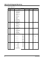
MicroTech Keypad Directory..............50
Lead-Lag of Refrigerant Circuits........ 25
Test Procedure - Trouble Analysis ......59
Manual Operation................................ 25
Testing Solid-State Relays...................64
Unit Status Modes ............................... 26
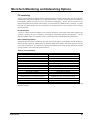
MicroTech Monitoring and Networking
Options ..................................................65
Circuit Status Modes ........................... 27
McQuay" is a registered trademark of McQuay International
1997 McQuay International
"Information covers McQuay International products at the time of publication and we reserve the right
to make changes in design and construction at anytime without notice"
2
OMRCPMICRO
Introduction
This manual provides installation, setup and troubleshooting information for the MicroTech controller
provided on McQuay reciprocating compressor chillers. Please refer to unit installation manuals for unit
application information as well as water and refrigerant piping details. All operating descriptions contained in
this manual are based on MicroTech controller software version RCPXX02G. Chiller operating characteristics
and menu selections may vary with other versions of controller software. Contact McQuayService for
software update information.
CAUTION
This equipment generates, uses and can radiate radio frequency energy and if not installed
and used in accordance with the instructions manual, may cause interference to radio
communications. It has been tested and found to comply with the limits for a class A digital
device, pursuant to part 15 of the FCC rules. These limits are designed to provide
reasonable protection against harmful interference when the equipment is operated in a
commercial environment.
Operation of this equipment in a residential area is likely to cause harmful interference in
which case the user will be required to correct the interference at his own expense.
McQuay International disclaims any liability resulting from any interference or for the
correction thereof.
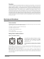
CAUTION
The McQuay MicroTech control panel contains static sensitive components. A static
discharge while handling electronic circuit boards may cause damage to the components.
To prevent such damage during service involving board replacement, McQuay recommends
discharging any static electrical charge by touching the bare metal inside the panel before
performing any service work.
CAUTION
Excessive moisture in the control panel can cause hazardous working conditions and
improper equipment operation.
When servicing equipment during rainy weather conditions, the electrical devices and
MicroTech components housed in the main control panel must be protected.
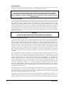
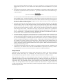
The MicroTech controller is designed to operate within an ambient temperature range of -40 to 149°F and a
maximum relative humidity of 95% (non-condensing).
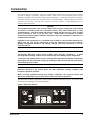
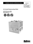
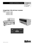
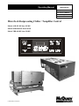
Figure 1, MicroTech Control
OMRCPMICRO
3
General Description
The MicroTech Unit Control Panel, available on some McQuay ALR, WHR, and THR products, contains a
Model 250 microprocessor based controller which provides all monitoring and control functions required for
the safe, efficient operation of the unit. The operator can monitor all operating conditions by using the panels
built in 2-line by 16-character display and keypad or by using an IBM compatible computer running McQuay
Monitor software. In addition to providing all normal operating controls, the MicroTech controller monitors all
safety devices on the unit and will shut the system down and close a set of alarm contracts if an alarm
condition develops. Important operating conditions at the time an alarm occurs are retained in the controllers
memory to aid in troubleshooting and analysis.
The system is protected by a simple password scheme which only allows access by authorized personnel. A
valid password must be entered into the panel keypad by the operator before any setpoints may be altered.
Features of the MicroTech Control Panel
Ø
Ø
Ø
Ø
Ø
Ø
Ø
Ø
Ø
Ø
Ø
Ø
Ø
Ø
Ø
4
Enhanced head pressure control on air-cooled units resulting in increased total unit SEER during
transitional seasons.
Preemptive control of high discharge pressures prior to a fault.
12-key keypad for adjusting water temperature set points, low water temperature cutout, high pressure
cutout, suction pressure cutout, and freeze protection. The operator can use the keypad to monitor
various operating conditions, setpoints or alarm messages.
Easy-to-read 2-line by 16-character display for plain English readout of operating temperatures and
pressures, operating modes or alarm messages.
Security password protection against unauthorized changing of set points and other control parameters.
Complete plain English diagnostics to inform the operator of pre-alarms and alarms. All alarms are time and
date stamped so there is no guessing of when the alarm condition occurred. In addition, some operating
conditions that existed at the instant of shutdown can be recalled to aid in isolating the cause of the
problem.
Soft Loading feature to reduce electrical consumption and peak demand charges during start-up.
Adjustable load pulldown rate reduces over-shoot during loop pulldown.
Easy integration into building automation systems via separate 4-20 milliamp signals for chilled water reset
and demand limiting (chillers only).
BAS communication capability via McQuay’s open protocol strategy to over 10 major BAS manufacturers.
Internal time clock for on/off scheduling.
14 holidays / dates with programmable duration.
Communications capabilities for local system monitoring, changing of set points, trend logging, remote
reset, alarm and event detection via IBM-compatible PC. The optional modem kit supports the same
features from an off-site PC running the McQuay Monitor software.
Manual control mode to override automatic unit staging, useful for system checkout.
Pressure transducers for direct reading of system pressures.
OMRCPMICRO
Optional Sensor Packages
Water and air sensor package
Air-cooled units:
Ø
Ø
Entering evaporator water temperature
Ambient outside air temperature
Water-cooled units only:
Ø
Ø
Ø
Entering evaporator water temperature
Entering condenser water temperature
Leaving condenser water temperature
Refrigerant sensor package
Ø
Ø
Ø
Ø
Suction line temperature, circuit #1
Suction line temperature, circuit #2
Liquid line temperature, circuit #1
Liquid line temperature, circuit #2 (Provides direct display of subcooling and superheat).
Unit amp package
Percent total unit amperage including compressors and condenser fans. Does not include externally powered
equipment such as water pumps.
OMRCPMICRO
5
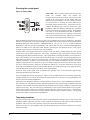
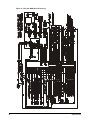
Controller Layout
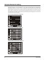
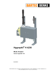
All major MicroTech components are mounted inside the control section side of the unit's control cabinet. The
individual components are interconnected by ribbon cables, shielded multi-conductor cables or discrete
wiring. Power for the system is provided by transformers T-2 and T-4. All field wiring must enter the control
cabinet through the knockouts provided and is terminated on field wiring terminal strips.
The standard ALR keypad/display is located inside the control cabinet for protection from the weather while
the back lit WHR and THR keypad/displays are accessible through the exterior of the control cabinet. See
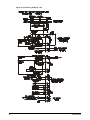
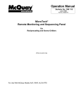
Figure 2 for typical control cabinet layout.
Figure 2, Typical control cabinet layout
6
OMRCPMICRO
Component Data
Microprocessor control board
The Model 250 Microprocessor Control Board contains the electronic hardware and software necessary to
monitor and control the unit. The microprocessor control board receives input from the Analog/Digital Input
Board (ADI) and sends commands to the output board, maintaining the unit's optimum operating mode for the
current conditions. Status lights mounted on the control board indicate operating condition of the
microprocessor.
Analog/digital input board (ADI)
The ADI board receives analog/digital signals from sensors and switches. The ADI board also provides
optical isolation between the microprocessor control board and all 24 volt switch inputs. LEDs on the ADI
board provide visual indication of the status of all digital inputs. All analog and digital signals from sensors,
transducers, and switches received by the ADI board and sent to the microprocessor control board for
interpretation.
Output board
The output board contains up to 16 solid-state relays and provides optical isolation between the control board
and Vac load volts. These relays control all compressors, condenser fans, solenoid valves, and alarm
annunciation. The output board receives control signals from the microprocessor control board through a 50
conductor ribbon cable.
Keypad and display
The keypad and display is the primary operator interface to the unit. Operating conditions, system alarms, and
set points can be monitored from this display. All adjustable set points can be modified from this keypad after
the operator has entered a valid password.
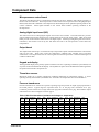
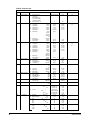
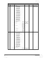
Thermistor sensors
MicroTech panels use a negative temperature coefficient thermistor for temperature sensing. A sensor
operating correctly will measure 3,392 ohmsat 72°F. See Table 1 for temperature conversion information.
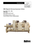
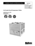
Pressure transducers
Pressure transducers are selected for a specific operating range and provide an output signal proportional to
the sensed pressure. Typical range for evaporator sensor is 5 to 145 psig with a resolution of 0.1 psig.
Condenser pressure sensors have a range of 20 to 450 psig and a resolution of 0.5 psig. The transducer output
characteristics are shown in Figure 3 and 4 on page 9.
Table 1, MicroTech thermistors (resistance and voltage vs. temperature)
Temp
°F
0
1
2
3
4
5
6
7
8
Temp Resistance
°C
Ohms
-17.8
25,617
-17.2
24,817
-16.7
24,044
-16.1
23,299
-15.6
22,579
-15.0
21,883
-14.4
21,212
-13.9
20,563
-13.3
19,937
VDC
Input
4.426
4.410
4.393
4.376
4.359
4.341
4.323
4.305
4.286
Temp
°F
50
51
52
53
54
55
56
57
58
Temp Resistance
°C
Ohms
10.0
5,971
10.6
5,814
11.1
5,662
11.7
5,514
12.2
5,371
12.8
5,231
13.3
5,096
13.9
4,965
14.4
4,838
VDC
Input
3.213
3.183
3,152
3.121
3.090
3.059
3.028
2.996
2.965
Temp
°F
100
101
102
103
104
105
106
107
108
Temp Resistance
°C
Ohms
37.8
1,747
38.3
1,708
38.9
1,670
39.4
1,633
40.0
1,597
40.6
1,562
41.1
1,528
41.7
1,494
42.2
1,461
VDC
Input
1.724
1.698
1.673
1.648
1.624
1.600
1.576
1.552
1.528
Table continued on next page.
OMRCPMICRO
7
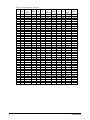
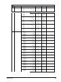
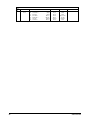
Table 1, Continued from previous page
Temp Temp Resistanc
°F
°C
e
Ohms
9
-12.8
19,332
10
-12.2
18,747
11
-11.7
18,182
12
-11.1
17,636
13
-10.6
17,108
14
-10.0
16,597
15
-9.4
16,104
16
-8.9
15,627
17
-8.3
15,166
18
-7.8
14,720
19
-7.2
14,288
20
-6.7
13,871
21
-6.1
13,467
22
-5.6
13,076
23
-5.0
12,690
24
-4.4
12,333
25
-3.9
11,979
26
-3.3
11,636
27
-2.8
11,304
28
-2.2
10,983
29
-1.7
10,672
30
-1.1
10,371
31
-0.6
10,079
32
0.0
9,797
33
0.6
9,523
34
1.1
9,258
35
1.7
9,002
36
2.2
8,753
37
2.8
8,512
38
3.3
8,278
39
3.9
8,052
40
4.4
7,832
41
5.0
7,619
42
5.6
7,413
43
6.1
7,213
44
6.7
7,019
45
7.2
6,831
46
7.8
6,648
47
8.3
6,471
48
8.9
6,299
49
9.4
6,133
8
VDC
Input
4.267
4.248
4.228
4.208
4.187
4.167
4.145
4.124
4.102
4.080
4.057
4.034
4.011
3.988
3.964
3.940
3.915
3.890
3.865
3.839
3.814
3.788
3.761
3.734
3.707
3.680
3.653
3.625
3.597
3.569
3.540
3.511
3.482
3.453
3.424
3.394
3.365
3.335
3.305
3.274
3.244
Temp Temp Resistanc
°F
°C
e
Ohms
59
15.0
4,714
60
15.6
4,594
61
16.1
4,477
62
16.7
4,363
63
17.2
4,252
64
17.8
4,146
65
18.3
4,042
66
18.9
3,941
67
19.4
3,843
68
20.0
3,748
69
20.6
3,655
70
21.1
3,565
71
21.7
3,477
72
22.2
3,392
73
22.8
3,309
74
23.3
3,228
75
23.9
3,150
76
24.4
3,074
77
25.0
3,000
78
25.6
2,927
79
26.1
2,857
80
26.7
2,789
81
27.2
2,723
82
27.8
2,658
83
28.3
2,595
84
28.9
2,534
85
29.4
2,474
86
30.0
2,416
87
30.6
2,360
88
31.1
2,305
89
31.7
2,251
90
32.2
2,199
91
32.8
2,148
92
33.3
2,099
93
33.9
2,051
94
34.4
2,004
95
35.0
1,959
96
35.6
1,914
97
36.1
1,871
98
36.7
1,829
99
37.2
1,788
VDC
Input
2.934
2.902
2.871
2.839
2.808
2.777
2.745
2.714
2.683
2.651
2.620
2.589
2.558
2.527
2.496
2.465
2.434
2.404
2.373
2.343
2.313
2.283
2.253
2.223
2.194
2.164
2.135
2.106
2.077
2.049
2.020
1.992
1.964
1.937
1.909
1.882
1.855
1.828
1.802
1.776
1.750
Temp Temp Resistanc
°F
°C
e
Ohms
109
42.8
1,430
110
43.3
1,398
111
43.9
1,368
112
44.4
1,339
113
45.0
1,310
114
45.6
1,282
115
46.1
1,254
116
46.7
1,228
117
47.2
1,201
118
47.8
1,176
119
48.3
1,151
120
48.9
1,127
121
49.4
1,103
122
50.0
1,080
123
50.6
1,058
124
51.1
1,036
125
51.7
1,014
126
52.2
993
127
52.8
973
128
53.3
953
129
53.9
933
130
54.4
914
131
55.0
895
132
55.6
877
133
56.1
859
134
56.7
842
135
57.2
825
136
57.8
809
137
58.3
792
138
58.9
777
139
59.4
761
140
60.0
746
141
60.6
731
142
61.1
717
143
61.7
703
144
62.2
689
145
62.8
676
146
63.3
662
147
63.9
649
148
64.4
627
149
65.0
625
VDC
Input
1.505
1.482
1.459
1.437
1.415
1.393
1.371
1.350
1.328
1.308
1.287
1.267
1.247
1.227
1.208
1.189
1.170
1.151
1.133
1.115
1.097
1.079
1.062
1.045
1.028
1.012
0.995
0.980
0.963
0.948
0.932
0.917
0.902
0.888
0.874
0.859
0.846
0.831
0.818
0.794
0.792
OMRCPMICRO
Figure 3, Evaporator transducer
OMRCPMICRO
Figure 4, Condenser transducer
9
Installation and Maintenance
The MicroTech controller is factory tested and configured for the unit being controlled.
Sensors and transducers
Sensors and transducers are mounted and connected to the MicroTech ADI board with shielded cable.
Transducers are on Shrader fittings and sensors are in wells except the optional suction and liquid line sensors
(in the refrigerant sensor package). The suction and liquid line sensors are placed in a copper sleeve that is
brazed to the copper tubing. Insulation is placed around the assembly.
Sensors and transducers are connected to the MicroTech analog inputs with IDC connectors (Insulation
Displacement Connectors).
To change the transducers, just unscrew and replace. The transducers have removable cables. High pressure
transducers have a red dot on them and low pressure transducers have blue dots. Sensors do not have
separate cables.
Control wiring
Low voltage control wiring is installed, labeled and tested by the factory before shipment.
Remote 4-20 milliamp signals
Signals for leaving water reset and demand limiting can be provided by the customer and should be connected
to the terminals on the field wiring strip inside the control cabinet. See the Field Wiring section for more
details.
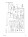
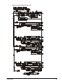
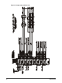
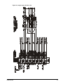
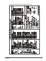
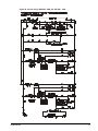
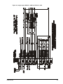
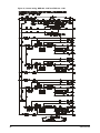
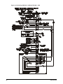
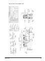
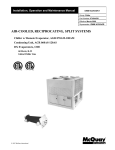
Interlock wiring
All interlock wiring to field devices (such as flow switches and pump starters) is provided by the installing
contractor. See Figure 5, unit wiring schematics, and field wiring diagrams at the end of this manual for details.
Unit set points and calibration
The control software is installed and tested by the factory before shipping. No periodic calibration of the
controller is necessary. All control and safety set points must be checked by the installing contractor and
adjusted as necessary before starting the unit. Controllers for McQuay chillers and Templifiers have default
set points (shown on Menus 13 through 22, in Table 8 on page 52) for:
Ø
Ø
Ø
Ø
Control mode
Leaving water temperature
Head pressure settings
Compressor staging
Ø
Ø
Ø
Ø
Softloading
Holiday dates
Internal scheduling
Alarm functions
The default set points are suitable for most installations.
On Menu 13, the default control mode is set for "Manual Unit Off". Adjust this setting before continuing with
unit operation. Check and set the control and safety settings for the application before staging the unit. For
more information on menu items, see the Menu Description section of this manual.
Modem kit
An optional modem kit allowing remote monitoring of the chiller from an off-site PC running the McQuay
Monitor software is available from McQuayService. The kit, complete with modem, mounting bracket, wiring
10
OMRCPMICRO
harness, and installation instruction can be installed in the field or at the factory. Modem wiring is shown on
the MicroTech wiring schematic. For more information, see "Telephone Line" in the Field Wiring section on
page 14.
Optional sensors
Optional sensor kits, available from the factory, can be installed in the field. Thermistors in the optional sensor
kit are negative coefficient type and have the same characteristics (see Table 1) as the thermistors used on
McQuay centrifugal chillers. Contact McQuayService for retrofit kits and ordering information.
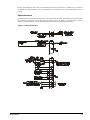
Figure 5, Typical field wiring
OMRCPMICRO
11
Field Wiring
Interconnecting wiring for the reciprocating control panel consists of:
Ø
Ø
Ø
Ø
Ø
Ø
Ø
Ø
115 VAC power wiring
Analog input signals
Digital input signals
Digital output signals
Condenser pump
Fan starter
Communications to a personal computer
Telephone line for remote modem access
See Figure 5 and unit field wiring diagrams at the end of this manual for more details.
Power wiring
Separate disconnects for the cooler heating tape and control circuit transformer are available as options on
ALR units. The installing contractor provides the 115 VAC power source, disconnect, 10 amp fuse, and
necessary wiring for these circuits. All wiring must conform to the National Electrical Code and applicable
local building code. If the separate power option is used, then the installing contractor must remove wires 540
and 545 from terminals #13 and #16 on TB2 before running the unit. See the ALR Field Wiring Diagram for
more detail.
Power supplies
There are several internal power supplies used by the controller and related circuitry. The regulated 5 VDC
power on terminal #214 is used to support the analog inputs on the ADI board. Do not use this power supply
to operate external devices. An unregulated 12 VDC power supply is available on field wiring terminal #146
and an unregulated 24 VAC power supply is available on field wiring terminal #25.
Analog input signals
All sensors and transducers required for normal chiller operation are installed and wired at the factory. All
optional analog signal wiring provided by the installing contractor must be twisted, shielded pair (Belden
#8760 or equal). Figure 5 and unit field wiring diagrams at the end of this manual for more detail. The optional
demand limit and leaving water reset signals are 4 to 20 milliamp DC signals. The resistive load that conditions
the milliamp signal is a 249 ohm resistor mounted on the ADI board at the factory.
Remote demand limit
To use the demand limit function, the installer will connect the wiring to terminals #131 and #132 on TB7.
Demand Limit can only be used on WHR and ALR units. See the MicroTech schematic and Field Wiring
diagrams at the end of this manual for more detail. More information on how Demand Limit works is available
in the Remote Demand Limit section on page 12 of this manual.
Leaving water reset*
Leaving water reset on ALRs, WHRs and THRs may be achieved by using the "4-20mA Reset" option on
Menu 14. The installer must connect wiring to terminals #134 and #135 on TB7. See the Reset Options section
of this manual for more detail.
12
OMRCPMICRO
Digital input signals
Remote contacts for all digital inputs into the MicroTech controller must be dry contacts suitable for the 24
VAC control signals from the reciprocating control panel. Do not connect 120 VAC control power to these or
any other connecting circuits.
Remote stop/start
If remote stop/start control is preferred, then remove the jumper between terminals #140 and #141 on TB7.
When the remote stop/start switch is open, the controller will be in the "off: remote Sw" mode. The unit is
enabled when the switch is closed.
Chilled water flow switch
The chilled water flow switch is connected to field wiring terminals #142 and #143 on TB7. When the chilled
water pump is enabled, the MicroTech controller checks for proof-of-flow through the flow switch digital input.
Digital outputs
The MicroTech output device is a normally open solid-state relay with an on-board, replaceable 5 amp fuse.
The status of all outputs are shown by individual red LEDs.
Chilled water pump relay
The optional chilled water pump relay is connected to terminal #10 on TB2. When the unit is enabled, the
chilled water pump relay is energized. Be sure the relay coil is rated for a maximum load of 1.8 amps at 120 VAC.
External alarm annunciator circuitry
An audible alarm connected to the Alarm Output of the reciprocating control panel is highly recommended to
make certain the operator is alerted to any alarm condition.
The MicroTech panel can activate an external alarm circuit when an alarm or pre-alarm condition is detected.
The alarm signal is de-energized during normal operations. During an alarm condition the alarm circuit will
energize and the alarm status light will be lit. During a pre-alarm condition, the alarm output and status light
will pulse "on" for one-half second and "off" for four seconds.
24 VAC is available at field wiring terminal #19 to power a bell, light, relay, or other external alarm devices. The
installing contractor must provide and install an alarm enunciator rated for a maximum load of 1.8 amps at 24
VAC. See the field wiring diagrams at the end of this manual for terminal locations.
Note: The alarm signal is not active during a power failure and will not provide a "Loss of Power"
alarm.
115 VAC power for the optional control transformer is obtained from the 3-phase power connection provided
by the electrical contractor.
Condenser fan wiring for chillers without condensers
The first fan of each circuit is to be wired in parallel with the first compressor stage for each circuit. Each
refrigerant circuit has three additional digital outputs available for refrigerant head pressure control. Each
output will energize an additional bank of condenser fans with each bank consisting of 1 or 2 fans, depending
on the size of the unit. The relays used to energize the fan motors must be rated for 120 VAC, 1.5 amps
maximum per coil. If a McQuay APD condenser is used, then the relays will be supplied by the factory. Relays
and fans are denoted as M12 through M24. The first number indicates the circuit while the second number
indicates the fan or fan bank number. See the Field Wiring Diagram and Staging Schematics at the end of this
manual for more detail.
Condenser pump or fan starter
Terminals #11 and #12 on TB2 on water-cooled units are reserved for starting the first fans of each circuit on a
remote condenser or for starting a single condenser pump. The relay coils should be rated for a maximum load
OMRCPMICRO
13
of 1.8 amps at 120 VAC. The terminals are wired in parallel with the compressor outputs so the coils will be
energized with the first compressor stage.
To start a condenser pump, install a jumper between terminals #11 and #12 and connect a single starter
between terminals #11 and #16 on TB2. When either of the lead compressor start, the condenser pump will
start.
To start a fan, connect the first fan of circuit #1 to terminals #11 and #16 on TB2. Connect the first fan of
circuit #2 to terminal #12 and #16 on TB2. When the lead compressor of a circuit starts, the first condenser fan
will start. See the Field Wiring Diagram and Compressor Control Schematics in the back of this manual for
more detail.
PC connection
The MicroTech controller can be connected to an IBM or IBM compatible computer for local or remote system
monitoring. Communication network wiring uses low voltage shielded twisted pair cable (Belden 8760 or
equal). The network uses the RS232 communications standard with a maximum cable length of 50 feet. An
RS232/485 adapter may be used to allow for cable runs to 5000 feet. See the Personal Computer Specification
section of this manual for hardware requirements.
Telephone line
If remote access and monitoring of the unit is chosen, then a voice quality direct dial telephone line is required.
The line must be a dedicated line and used only for modem access. The phone line must be terminated with a
standard RJ-11 modular phone plug. See the Start-Up and Shutdown section on page 39of this manual for
more detail on start-up procedures.
14
OMRCPMICRO
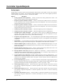
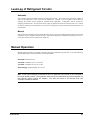
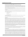
Software Identification
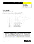
Control software is factory installed and tested in each panel prior to shipment. The software is identified by a
program code which is printed on a small label attached to the controller. The software version may also be
displayed on the keypad display be viewing the last menu item in the Misc Setup menu (menu 23).
The software "version" is the 6th and 7th digit of the software identification. In this example, the version is
"02" and the revision to the software is "G". Revisions are released in alphabetical order.
The new reciprocating codes are from a single master code which combined chiller and Templifier functions.
The new code enables selection of chiller or chiller/Templifier operation. A high memory chip is required to run
this software. Controller series 250-4 and greater can successfully run on chiller/Templifier software versions.
Example of typical software identification
RCP 2 E 01 B
Revision (A, B, C, etc.)
Version (1, 2, 3, etc.)
English/U.S. customary display units (S=SI/metric)
R-22 refrigerant (3=R-134a refrigerant)
Reciprocating chiller/Templifier code
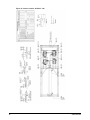
Figure 6, Software ID tag
McQuay
06/01/95
Date Shipped
P/N 950820A-01-A
Part Number
S/N 1058
Serial Number
Ver. RCP2E01B
Software Version No.
OMRCPMICRO
15
Controller Inputs/Outputs
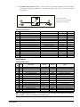
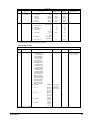
Analog inputs
Analog inputs are used to read the various temperatures and pressures on the chiller as well as any customer
supplied 4-20mA reset signals. The controller's internal regulated 5 VDC and 12 VDC supplies provide the
correct operating voltage for the sensors. See Table 2 for details.
Input No.
16
Description
0
Leaving evaporator water temperature - Sensor is located in the leaving chilled water nozzle. The
signal is used for capacity control and freeze protection.
1
Evaporator pressure transducer circuit #1 - Sensor is located in the common circuit #1 suction line.
Used to determine suction saturated refrigerant pressure and temperature. This sensor also provides
refrigerant freeze protection for circuit #1.
2
Evaporator pressure transducer circuit #2 - Sensor is located in the common circuit #2 suction line.
Used to determine suction saturated refrigerant pressure and temperature. This sensor also provides
refrigerant freeze protection for circuit #2.
3
Condenser pressure transducer circuit #1 - Saturated refrigerant pressure and temperature.
4
Condenser pressure transducer circuit #2 - Saturated refrigerant pressure and temperature.
5
Transducer power voltage ratio signal - The signal is used to correct for differences between the
controller power supply and an ideal 5 VDC supply. The controller uses this information to ensure
temperature and pressure sensor accuracy and for alarm monitoring.
6
Evaporator water temperature reset - A 4 to 20 milliamp DC signal from a building automation system
or temperature transmitter to reset the leaving chilled water set point. The impedance of the ADI board
is 249 ohms.
7
Demand limit - A 4 to 20 milliamp signal from a building automation system to determine the maximum
number of cooling stages which may be energized. The impedance of the ADI board is 249 ohms.
8
Chiller/Templifier signal (on THR heat pumps only) - In place of the Demand Limit input, a 0 or 5 volt
signal from a unit mounted switch allows the unit to run in heat (0 volts - switch open) or cool (5 volts switch closed) modes.
9
Entering evaporator water temp (optional) - Sensor is located in the entering chilled water nozzle. The
signal is used for monitoring and for the return reset option if selected.
10
Entering condenser water temp (optional) (O.A. temp for air cooled units) - Sensor is located in the
common entering condenser water nozzle or located remotely as an outside air temp sensor for air
cooled units. This sensor is used for monitoring purposes only.
11
Leaving condenser water temperature (standard on THR heat pumps; optional on WHR chillers) - For
WHRs, sensor is located in leaving water nozzle of one condenser only. For THRs, sensor is located in
common line of manifolded condenser head. The signal is used for capacity control on THRs and for
monitoring only on WHRs.
12
Percent of total unit amps (optional) - A current transformer and adjustable voltage dropping resistor
located in the power side of the control box along with a voltage converter board sends a DC signal
proportional to total motor current to the microprocessor. O VDC = 0%, 4 VDC = 100%
13
Suction temp circuit #1 (optional) - Sensor located in a copper sleeve brazed to the circuit #1 suction
line measures refrigerant temperature to calculate superheat. This sensor is used for monitoring
purposes only.
14
Suction temp circuit #2 (optional) - Sensor located in a copper sleeve brazed to the circuit #2 suction
line measures refrigerant temperature to calculate superheat. This sensor is used for monitoring
purposes only.
15
Liquid line temp circuit #1 (optional) - Sensor located in a copper sleeve brazed to the circuit #1 liquid
line measures refrigerant temperature to calculate subcooling. This sensor is used for monitoring
purposes only.
OMRCPMICRO
16
Liquid line temp circuit #2 (optional) - Sensor located in a copper sleeve brazed to the circuit #2 liquid
line measures refrigerant temperature to calculate subcooling. This sensor is used for monitoring
purposes only.
Front panel mount
heat/cool switch front panel
mount heat/cool switch
Table 2, Analog inputs
Input
0
1
2
3
4
5
6
7
8
9
10
11
12
13
14
15
Function
Leaving Chw temperature
Circuit #1 Evaporator Pressure
Circuit #2 Evaporator Pressure
Circuit #1 Condenser Pressure
Circuit #2 Condenser Pressure
Voltage Ratio Signal
Chw Reset Signal
Demand Limit Signal
Entering Evaporator Water Temperature
Entering Condenser Water Temperature
Leaving Conderser Water Temperature
% Total Unit Amps
Circuit #1 Suction Temperature
Circuit #2 Suction Temperature
Circuit #1 Liquid Line Temperature
Circuit #2 Liquid Line Temperature
Location
Leaving Chw Nozzle
Circuit #1 Suction Line
Circuit #2 Suction Line
EnGinn Power Supply
Supplied By Others
Supplied By Others
Entering Chw Nozzle
Entering Condenser Water Nozzle
Leaving Condenser Water Nozzle
Control Cabinet
Circuit #1 Suction Line
Circuit #2 Suction Line
Circuit #1 Liquid Line
Circuit #2 Liquid Line
Range
-40 to 263°F
5 to 145 psig
5 to 145 psig
20 to 450 psig
20 to 450 psig
4 to 20mA DC
4 to 20mA DC
-40 to 263°F
-40 to 263°F
-40 to 263°F
0 to 4 VDC
-40 to 263°F
-40 to 263°F
-40 to 263°F
-40 to 263°F
Resolution
0.1°F
0.1 psi
0.1 psi
0.5 psi
0.5 psi
0.1°F
0.1°F
0.1°F
1%
0.1°F
0.1°F
0.1°F
0.1°F
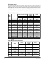
Digital inputs
Table 3, Digital inputs
Inpu
t
0
1
2
3
4
5
6
7
8
9
10
11
12
13
14
15
LED
Description
Circuit
Closed
Open
0
1
2
3
4
5
6
7
8
9
10
11
12
13
14
15
Mechanical high pressure switch
Oil differential pressure switch
Motor protection switch
Oil differential pressure switch
Motor protection switch
System switch
Phase/voltage monitor
Pumpdown switch
Mechanical high pressure switch
Oil differential pressure switch
Motor protection switch
Oil differential pressure switch
Motor protection switch
Remote stop switch
Water flow switches
Pumpdown switches
Circuit #1
Compressor 1
Compressor 1
Compressor 3
Compressor 3
Unit
Unit
Circuit #1
Circuit #2
Compressor 2
Compressor 2
Compressor 4
Compressor 4
Unit
Unit
Circuit #2
Normal
Normal
Normal
Normal
Normal
Normal
Normal
Normal
Normal
Normal
Normal
Normal
Normal
Run
Normal
Normal
High discharge pressure
Low oil pressure
High motor temperature
Low oil pressure
High motor temperature
Unit shutdown
PVM alarm
Manual pumpdown
High discharge pressure
Low oil pressure
High motor temperature
Low oil pressure
High motor temperature
Pumpdown & stop
No evaporator (condenser) flow
Manual pumpdown
Note: All Digital Inputs are 24 VAC. At 7.5 VAC to 24 VAC the digital input contacts are considered
closed. Below 7.5 VAC, the contacts are considered open.
OMRCPMICRO
17
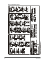
Relay board outputs
All of the MicroTech panel outputs are controlled by solid-state relays which are driven by the model 250
controller. The controller activates a solid-state relay by sending a "trigger" signal to the output board via the
attached ribbon cable. The relay responds to the trigger by lowering its resistance which allows current to
flow through its "contacts". When the controller removes the trigger signal, the relay's resistance becomes
very high, causing the current flow to stop. The outputs are individually protected by a 5 amp fuse mounted
on the output board adjacent to each relay. Table 4 and Table 5 provide additional information about each
output. Refer to the MicroTech Stage Schematics for digital output wiring.
Table 4, ALR relay board outputs
Digital
Output
Number
0
Output
Description
4-Stage Compressor Capacity
2-Compressor
035-070
050-070
Same
Same
2
3
Alarm Circuit
Chilled Water
Pump Relay
Liq Sol circ #1
Liq Sol circ #2
4
Cooling
5
Cooling
6
Cooling
7
Cooling
8
Cooling
Not Used
Not Used
9
Cooling
Not Used
Not Used
1
10
11
12
13
14
15
Note:
6-Stage
Compressor
Capacity
2-Compressor
050-070
Same
8-Stage Compressor
Capacity
4-Compressor
085-185
Same
Same
Same
Same
Same
Same
Same
Compressor 1
Circuit #1
Compressor 2
Circuit #2
Compressor 1
Unloader 1
Compressor 2
Unloader 1
Same
Same
Compressor 1
Circuit #1
Compressor 2
Circuit #2
Compressor 1
Unloader 1
Compressor 2
Unloader 1
Same
Same
Compressor 1
Circuit #1
Compressor 2
Circuit #2
Compressor 1
Unloader 1
Compressor 2
Unloader 1
Compressor 1
Unloader 2
Compressor 2
Unloader 2
Same
Same
Same
Compressor 1
Circuit #1
Compressor 2
Circuit #2
Compressor 1
Unloader 1
Compressor 2
Unloader 1
Compressor 3
Unloader 1
Compressor 4
Unloader 2
Same
Condenser Fan(s) M12
Same
Same
j
Condenser Fan(s) M13
Same
Same
Same
Condenser Fan(s) M14
Same
Same
Same
Condenser Fan(s) M22
Same
Same
Same
Same
Condenser Fan(s) M23
Same
Same
Same
Condenser Fan(s) M24
Same
Same
Same
j Number of fans varies. Refer to the Head Pressure Control section on page 28 of this manual for Fan Staging
information.
Table 5, WHR and THR relay board outputs
Digital
Output
Number
0
Output
Description
2
3
Alarm Circuit
Chilled Water
Pump Relay
Liq Sol circ #1
Liq Sol circ #2
4
Cooling
5
Cooling
6
Cooling
1
18
4-Stage Compressor
Capacity
8-Stage Compressor
Capacity
2-Compressor
WHR 040-085E
THR 040-110D
Same
6-Stage
Compressor
Capacity
2-Compressor
WHR 070-085E
THR 070-110D
Same
Same
Same
Same
Same
Same
Compressor 1
Circuit #1
Compressor 2
Circuit #2
Compressor 1
Unloader 1
Same
Same
Compressor 1
Circuit #1
Compressor 2
Circuit #2
Compressor 1
Unloader 1
Same
Same
Compressor 1
Circuit #1
Compressor 2
Circuit #2
Compressor 1
Unloader 1
4-Compressor
WHR 095-210E
THR 120-170D
Same
OMRCPMICRO
7
Cooling
Compressor 2
Unloader 1
8
Cooling
Not Used
9
Cooling
Not Used
10
Condenser Fan(s) M12
k
Condenser Fan(s) M13
k
Condenser Fan(s) M14
k
Condenser Fan(s) M22
k
Condenser Fan(s) M23
k
Condenser Fan(s) M24
k
11
12
13
14
15
Same
Compressor 2
Unloader 1
Compressor 1
Unloader 2
Compressor 2
Unloader 2
Same
Compressor 2
Unloader 1
Compressor 3
Circuit 1
Compressor 4
Circuit 2
Same
Same
Same
Same
Same
Same
Same
Same
Same
Same
Same
Same
Same
Same
Same
Same
Note: kCondenserless WHR only.
User selectable reset options are found under Menu 14, item line G "ResetOpt= " for chillers and item line H
"Reset Sig= ##.#mA" for Templifiers. Most reset options apply to leaving chilled water only—ALRs, WHRs,
and THRs operated in chiller mode. The only reset options available for THRs operated in heating mode
(controlled by leaving condenser water) are: "None", "4-20mA", and "Network". Selected reset option
settings for chilled and heated water temperatures are displayed in Menu 14.
None
"None" is the Default Values setting. When selecting "None", the following applies:
Ø
Ø
Ø
Leaving evaporator water temperature or leaving condenser water temperature, whichever is applicable
control the unit.
Leaving evaporator water temperature control ALRs, WHRs, and THRs operating in the "chiller" mode.
Leaving condenser water temperature control THRs operating in "heat pump" mode.
Return
By selecting "Return" as the reset mode, the controller resets the leaving chilled water temperature set point as
required to maintain a constant return water temperature. To choose "Return" as the reset option, first select
"Return" in the "ResetOpt" mode and press <ENTER>, then in the "ReturnSpt" item, select the return water set
point temperature to be maintained. The return water set point algorithm is internal to the controller. No other
action is required.
4-20mA (remote reset signal)*
By selecting "4-20mA" as the reset option, the controller will reset the leaving chilled water temperature to a
higher value based on a percentage of the Maximum Chilled Water Reset ("MaxChWRst"). At 4mA, the chilled
water set point resets to a value equal the Leaving Evaporator Water Set Point ("Lvg Evap") plus the
MaximumChilled Water Reset ("MaxChWRst") set point. Any valuebetween 4 and 20mA will add a
proportional value of the Maximum Chilled Water Reset to the Leaving Chilled Water Set Point. The reset
schedule is linear and may be determined using Figure 7, Leaving Water Reset, below. The external 4-20mA
control signal displays under "ResetSig=" on Menu 14.
For THRs operated in heating mode, the "Lvg Evap" indicates the degree of heating reset. Using the 4-20mA
reset signal, a proportional value of the Maximum Chilled Water Reset "MaxChWRst" is subtracted from the
Leaving Condenser Water Set Point ("Lvg Cond" Menu #4). The reset control signal will display on Menu
#14, item line "Reset Sig". The reset schedule is linear and may be determined using Figure 7, Leaving Water
Reset, below.
Terminals #134 and #135 on TB7 are the field wiring 4-20mA remote reset terminal. See the field wiring
diagrams in the back of this manual for more detail.
OMRCPMICRO
19
Figure 7, Leaving water reset
Ice (remote reset signal)
When in "Ice" mode, all compressors will run 100% loaded (that is no unloaders energized) to make certain that
compressors cool appropriately. As a result, the number of stages in "Ice" mode will equal the number of
compressors. Use approved solutions in the chilled water loop to protect the system to at least 15°F lower
than the ice setpoint. When Leaving Evaporator Water (Lvg Evap") is set less than 34°F, "Ice" mode must be
used. Cylinder unloading of compressors when suction temperatures fall below 25°F will prevent the
compressor motor from cooling adequately. The lowest Leaving Water Ice set point for McQuay reciprocating
chillers is 21°F. With an Ice set point of 21°F, saturated suction temperatures of 12°F or 13°F are typical. This
is the lowest recommended saturated suction temperature for McQuay reciprocating products.
Most ice storage applications require dual reset control. Use terminals #134 and #135 on TB7 for field wiring 420mA remote reset connections. See the field wiring diagrams at the end of this manual for more detail.
IMPORTANT
If a 4-20mA signal device is not available, a dual contact is required, then a dry contact
between terminals #215 and #135 may be used to initiate reset. When using a dry contact,
"open" will maintain the ice set point and "close" will initiate a full reset.
If the chiller is to be used for ice storage, select the "Ice" option in Menu 14. "LvgWater Spts", "ResetOpt=".
To calculate the leaving chilled water set point, the control band (Menu 14 "CntrlBand=") and shut down
delta-T (Menu 14 ShutDn D-T=") must first be selected. The equation to determine leaving chilled water
temperature:
Lvg Evap = Desired Ice Temp + 1/2"CntrlBand + " "ShutDn D-T"
Lvg Evap = 21°F + 1/2 (4) + 1.5°F
LvgEvap = 21 +2+ 1.5
Lvg Evap = 24.5
For day operation the maximum chilled water reset (Menu 14 "MaxChWRst=") is added to the "Lvg Evap" as
calculated above to reach the desired day operating leaving chilled water temperature.
When the Ice option is selected, the resetting of the leaving chilled water set point (during day operation) via
the 4-20mA input is not a functional option. To retain the option, the set points in Menu 14 must be changed
by a Building Automation System through our MicroTech Open Protocol Monitor Software.
When a 4-20mA signal is used to initiate ice reset, if a signal less than 4mA is received, nothing happens—the
ice mode temperature will be maintained. When a signal of 4mA or more is received, the unit changes to a nonice building mode temperature. The control signal will be displayed under "Reset Sig" on Menu #14.
The alarm setpoints (see Menu 22) will also need to be adjusted. The following is an example of alarm set
points for a typical ice operation:
20
OMRCPMICRO
1.
"Frz Stat": Set to the saturated refrigerant pressure that corresponds to a temperature equal to 13.5°F
below the ice set point. For example, if the ice set point is 23°F, the "Frz Stat" would be set at 33 psig,
(which is 23°-13.5° = 9.5°F; 33 psig is R-22 saturation pressure at 9.5°F).
2.
"Frze H2 O": Set at least 4°F below the ice set point, but not lower than the freezing point of the solution.
In this example, the "Frze H2 O" would be set at 19°F.
3.
"LP CutOut": Set 8 to 10 psi below the "Frz Stat" setting but never below 20 psig.
4.
"LP Cutin": Set 15 to 20 psi above "LP CutOut".
5.
FreezeTimer ("FreezeTim") and Condenser High Pressure ("Hi Press"): Do not need to be adjusted.
Network
Based on the Maximum Chilled Water Reset Set Point ("MaxChWRst"), the "Network" option allows a signal
to be sent that reflects 0 to 100% reset of the Leaving Chilled Water Set Point ("Lvg Evap") for chillers (except
Ice mode) or Leaving Condenser Water Set Point ("Lvg Cond") for THRs. This option functions similar to the
4-20mA option.
OMRCPMICRO
21
Remote Demand Limiting
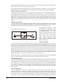
Demand limiting applies to ALR and WHR chillers only. Remote demand limiting may be accomplished by
connecting to terminals #131 and #132 on TB7. A 4-20mA signal is required. Based on the 4-20mA signal,
demand limiting will cause the chiller to limit the total number of stages regardless of the amount of cooling
actually required. A signal of 4mA or less allow all stages to operate while a 20mA or more will allow only one
stage to operate. The effect of the 4-20mA signal may be determined using Figures 8, 9 and 10. Under Menu
#18, demand limits, the number of stages allowed by demand limiting will be displayed as well as the actual
remote demand limit signal in milliamps.
Figure 8, Remote demand limit, 4-stage unit
Figure 9, Remote demand limit, 6-stage unit
Figure 10, Remote demand limit, 8-stage unit
22
OMRCPMICRO
THR Heat/Cool Changeover
On THR heat pumps, instead of the demand limit input, a 0 to 5 volt signal from a front panel unit-mounted
switch allows the unit to run in heat and cool modes. Five volts is obtained at terminal #215, wired through the
unit mounted switch and then connected to terminal #132 on TB7. When the switch is "open", the unit is in
heating mode. When the switch is "closed" the unit is in cooling mode. Menu #18 shows which mode the unit
is in. "ChVTmp Sig = Temp" denotes heating mode and "Chl/Tmp Sig = Chil" denotes cooling mode. In chiller
mode, the unit is controlled by the leaving evaporator water. To operate the unit as a Templifier, choose
"ChlTmp" under Item E of Menu #23. See Normal Sequence of Operation section of this manual for more
information.
Soft Loading
Soft loading limits the number of available stages when the unit is started to prevent excessive power
consumption and possible overshoot of the leaving water temperature set point. Soft loading is in effect
whenever the unit is started from an "off" cycle. This option is selectable and available in Menu 15.
On initial start-up, the controller will run the chilled water pump and sample the loop water temperature for a
time equal to the Load Delay set point ("LoadDelay") on Menu 15. If cooling or heating is required at the end
of the time delay, then the liquid line solenoid valve will be open and refrigerant will flow. When the
evaporator refrigerant pressure rises above the LP Cut In Set Point ("LP CutIn" see Menu #22), the controller
will start the first compressor. On entering the "Stage" the controller starts a countdown timer to indicate how
long the unit has been in the cool or heat stage mode. The number of stages allowed during soft loading is
determined by the Soft Load Maximum Stages ("SoftLdMaxStg" see Menu #15). The duration of the soft load
sequence is determined by the Soft Load Timer ("SoftLoad" see Menu #15). If the Soft Load Timer is set to
zero, no soft loading will take place. When the soft load option is enabled, any time remaining in the Soft Load
Timer will be displayed on Menu 15 under item "Time Left".
The following set points may be adjusted on Menu 15:
Ø
Ø
Ø
OMRCPMICRO
Soft Load: This is the amount of time soft loading will be in effect after the controller begins staging. If set
to zero, no soft loading is cancelled.
SoftLdMaxStg: Determines the maximum number of cooling or heating stages which may be energized
while soft loading is in effect.
LoadDelay: The amount of time allowed for the controller to sample the loop water temperature before
initiating cool or heat stages.
23
Compressor Control
The compressor staging logic uses an adjustable control band and interstage timer to determine the correct
number of cooling or heating stages to activate. A project-ahead temperature calculation and a maximum pull
down rate provide stable operation. Compressor set points are shown on Menu 16.
The Control Band is the temperature range on either side of the active leaving water set point that must be
exceeded for a stage change to occur. When in chiller mode and after the unit has started, the controller will
stage-up when the leaving water temperature rises to the Leaving Chilled Water Set Point plus half of the
Control Band. The controller will stage-down when the leaving water temperature lowers to the Leaving
Chilled Water Set Point minus half the Control Band. The THR, controlled from leaving condenser water,
stages up and down in the reverse order of a unit in chiller operation.
The adjustable compressor Interstage Timer set point ("InterStg", see Menu #16) sets the time delay between
the current cooling or heating stage and the next stage-up request. The compressor stage-down time delay is
fixed at a 1/3 ratio of the stage-up setting. For more information on staging, refer to the "Normal Sequence of
Operation" section on page 37 of this manual.
The controller performs a project-ahead temperature calculation to protect against an overshoot condition
when the leaving water temperature is outside the control band. Project-ahead calculation also moderates the
controller's response to a rapid increase and decrease in leaving water temperature. During cooling mode, if
the chilled water temperature is above the control band and the project-ahead calculation has determined that
the chilled water temperature will fall below the control band within 240 seconds (4 minutes), then the
controller will unload the compressors and stage-down the unit until the condition is no longer true. For THRs
in the heating mode, if the project-ahead calculation has determined that the leaving condenser water
temperature will rise above the control band wishing 240 seconds (4 minutes), then the controller will unload
the compressors and stage-down the unit until the condition is no longer true.
As additional protection against overshooting the unit set point, the controller uses the maximum pull down
rate ("MaxPullDn", on Menu #14) to determine if the leaving water temperature is pulling down or up too
rapidly. Every minute, the controller checks the leaving water temperature and compares the temperature to the
last reading. If the Pull Down Rate is exceeded, the controller delays additional stages. Maximum Pull Down
("MaxPullDn", on Menu #14) default setting is 0.5°F. This setting may be changed on Menu 14, Lvg Evap
Spts,.
The MicroTech soft loading feature will also guard against problems of overshooting the set point. The Soft
Load ("SoftLoad" on Menu #15) default setting is 20 minutes up to stage 4 of cooling and heating stages. See
"Soft Loading" section of this manual for more information.
The Interstage Timer ("InterStg" on Menu #16) default setting is 180 seconds for cooling and heating stages.
Interstage timers (anti-cycle) for compressors are 5 minute stop-to-start and 15 minute start-to-start.
24
OMRCPMICRO
Lead-Lag of Refrigerant Circuits
Automatic
The controller provides automatic lead-lag of refrigeration circuits. The circuit having the fewest number of
starts on all compressors in the circuit will be started first. Changes to circuit capacity will be made by
changing the position of the compressor unloaders when applicable. Compressors will be selected by
changing unloader status. This prevents short-cycling of compressors when the cooling load is low. If both
circuits are operating and a stage-down to one circuit is required, the circuit with the most operating hours will
cycle off first.
Manual
The operator may manually select the lead refrigerant circuit or have the controller automatically select the lead
refrigerant circuit to equalize compressor hours. Automatic lead-lag may be defeated by selecting circuit #1 or
circuit #2 as the lead circuit ("Lead Circuit" Menu 16).
Manual Operation
Manual operating modes are available to facilitate setup and troubleshooting of the unit. Any of the following
manual modes may be selected from the Control Mode Menu.
ManualOff: Manual unit off.
Auto1Off2: Automatic Circ #1, Circ #2 off.
Auto2Off1: Automatic Circ #2, Circ #1 off.
ManualStaging: Manual Staging, Circ #1 & 2.
Note: These manual settings are intended to aid in troubleshooting and should not be considered to
be normal operating modes. The equipment should not be left unattended during manual operation as
the automatic staging controls are disabled. The chiller will remain in the manual mode until
Automatic operation is selected.
OMRCPMICRO
25
Unit Status Modes
The operating status of the unit is displayed on the keypad/display when the information is requested by the
operator. Description of each Unit Status Mode are listed below.
"Off: Remote SW" mode
Upon start-up, the panel will check the "Remote Stop Switch" digital input. If the switch is open, the controller
will be in the "Off: Remote SW" mode. Note that from the factory, the unit will ship with a mechanical jumper
between the field terminals. If remote stop/start control is desired, remove jumper between terminals 140 and
141.
"Off: Time Clock" mode
If the controller has been commanded to an off state via the internal time clock (Menu 20), the mode will be
"Off: Time Clock". Note that if a customer wishes the unit to run 24 hours per day, the eight day clock must be
set to start at 00:00 and stop at 23:59 for all days.
"Starting" mode
If the remote stop switch is closed and the internal time clock is calling for the unit to run, the controller will
initiate "Starting" mode.
"Wait for Flow" mode
The chilled water pump output relay is energized any time the unit is enabled. The controller will check for the
presence of chilled water flow via the normally open flow switch. If flow is not proven within 30 seconds, the
alarm "LossofWater Flow" will be activated and the unit will remain in the "Waiting for Flow" mode until water
flow is proven. Once flow is established, the alarm will automatically be cleared.
Loss of water flow during unit operation will cause the unit to log the alarm and return to the "Waiting for
Flow" state. When chilled water flow has been re-established, the alarm will again automatically be cleared.
"Wait for Load" mode
With water flow established, the controller will wait for a period of time equal to the "Load Delay" set point to
determine if the water loop is above or below the current active water set point. In chiller mode, if leaving
chilled water temperature is above the leaving chilled water set point plus 1/2 of the control band plus the
start-up delta-T, the controller will enter the stage mode otherwise the controller will wait until the end of the
currently scheduled run period.
In heating mode (Templifier only), if the leaving condenser water temperature is below the leaving condenser
water set point minus 1/2 the control band minus the start-up delta-T, the controller will enter the stage mode.
"Stages 1-8"
This is the normal mode the unit will be in while cooling or heating. The number of currently active stages will
be displayed. The stage is only an indicator of system capacity and does not indicate which compressors or
circuits are on.
"Off: Alarm"
This is the mode which will be displayed when a circuit is in an alarm condition which means no cooling or
heating on that circuit is possible. Refer to the System Alarms and Circuit Alarms sections in this manual for
additional details.
"Off: Manual" mode - If the control mode of the unit is "Manual Off" the unit status will be displayed as "Off:
Manual" mode.
"Off: PumpDnSw's" - If the pumpdown switch digital inputs for both circuits are in the "manual " position,
the mode of the unit is "Off: PumpDnSw's".
"Manual Stage" - If the control mode of the unit is "Manual Stage" the unit status will be displayed as
"Manual Stage".
26
OMRCPMICRO
"Stage Up", "Stage Down" - These are momentary operating modes indicating a stage up or stage down is
being initiated by the controller.
"Off: System Sw" mode - Upon start-up the panel will check the front panel "System Switch" position. If the
switch is in the "stop" position, the mode will be "Off: System Sw".
Circuit Status Modes
The operating status of each refrigeration circuit is displayed on the keypad/display when the information is
requested by the operator. Descriptions of each Circuit Status Mode are listed below.
"Off:System Sw" - Off due to System Switch.
"Off: Manual Mode" - Off due to Control Mode Set Point.
"Off: Alarm" - Off due to Alarm Condition.
"Off:PumpDnSw" - Off, the circuit pumpdown switch is in the manual position.
"Off: CycleTime" - Off due to anti-cycle timers.
"Off: Ready" - Off Ready to start or Standby.
"Pumping Down" - The circuit is in the process of pumping down, the solenoid valve is closed.
"Open Solenoid" - A request has been made for the circuit to be energized for cooling or heating, the solenoid
is open and the controller is waiting for the pressure to rise above the LPCutIn set point.
"% Capacity" - Circuit is running, all operating conditions are normal. The circuit percent capacity is
displayed.
OMRCPMICRO
27
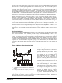
Head Pressure Control
Air-cooled units only (ALRs & WHRs with remote condensers)
For each circuit, the first stage of condenser fans is wired in parallel with the compressor output so that they
are energized with the first compressor stage. The fans for each circuit are controlled independently, but use
the same Head Pressure Set Points for staging. The transducers responsible for measuring condenser
pressure are mounted on the head of the lead compressors' discharge. Refer to the sensor location charts
towards the back of this manual for specific locations.
Each circuit has three additional digital outputs available for refrigerant head pressure control. Each output
will energize an additional bank of condenser fans with each bank consisting of 1 or 2 fans, depending on the
size of the unit.
The number of condenser fan stages per circuit controlled by MicroTech head pressure control is the number
of fan contactors per circuit minus 1 since the first fan comes on with the compressor. The number of fan
stages for each unit size is as follows:
ALR-035, 040D/E.............................................................1
ALR-050D/E......................................................................2
ALR-060 thru 185D/E .....................................................3
Air-cooled unit EERs are maximized by not allowing condenser fan stage 3 (the last fan stage) to operate when
the unit capacity is below 50%.
Above 50% capacity, unit EER is maximized by energizing as many condenser fan stages as possible.
Lift pressure
The minimum acceptable lift pressure is determined by the expansion valve. "Lift Pressure" is defined as the
difference between the saturated condensing pressure and the saturated evaporator pressure—or the minimum
differential pressure to be maintained across the expansion valve. The "MinLift-35%" and the "MinLift-100%"
set points on Menu 17, "Head Pres Spt" reflect the desired lift pressures at 35% and 100% circuit cooling
capacity. At low circuit capacities, it is desirable to maintain a minimum lift of 85 psig. The first fan stage
comes on with the first stage of compressors and the cooling capacity is roughly 33-35%. That is when the
MicroTech starts evaluating the necessity of bringing on the second stage of fans. The Minimum Lift-35% set
point is the minimum differential pressure to be maintained across the expansion valve when the unit is
running at 35% circuit capacity. At higher tonnage capacities, a higher lift pressure must be maintained to
accommodate the increased flow through the expansion valve. The Minimum Lift-100% set point is the
minimum differential pressure to be at 100% capacity. At 100% circuit cooling capacity, a lift pressure of about
140 psig should be maintained to provide proper flow through the TXV. This is the default setting for the
"MinLift100%" setting. Even though the adjustable range for this item is 120-180, 140 should be the maximum
used for virtually all cases to prevent high pressure alarms.
The lift pressure between 35% and 100% circuit capacity cooling is linear as shown in Figure 11. The Minimum
Lift -35 % and -100% endpoints define a minimum lift pressure line which provides the MicroTech controller
with the correct minimum lift pressure to be maintained at any unit operating capacity.
Fan staging logic
In the MicroTech logic, there are set dead band values which define pressure differential ranges above the
minimum lift pressure within which no condenser fan staging will occur. The dead band table is shown in
Figure 11. The dead band value used is based on the current circuit capacity and current number of condenser
fans in operation as shown in the table. The dead band range lies entirely above the minimum lift pressure line.
In Figure 11, the dead bands are graphically illustrated as the vertical distance between the minimum lift
pressure line and the fan staging lines. No additional fan staging occurs if the head pressure is within the
dead band zone. If the head pressure moves outside the dead band, the controller integrates the pressure error
over time. The error calculation is based on minimum condenser pressure ("MinCondPr") and maximum
condenser pressure ("MaxCondPr") values which MicroTech calculates internally. The values are calculated
28
OMRCPMICRO
for each circuit and are based on the current evaporator pressure, the point on the minimum lift pressure line at
which the unit is currently operating, and the current dead band being used. The "MinCondPr" equals the
current evaporator pressure plus the point value on the minimum lift pressure line at which the unit is currently
operating. Since the pressure scale in Figure 11 is referenced to evaporator pressure, the "MinCondPr" is
represented by the minimum lift pressure line in Figure 11. "MaxCondPr" equals the current "MinCondPr" plus
the current dead band value from Figure 11. Thus, the point value on the current fan staging line represents
the "MaxCondPr". If the dead band multiplier is anything other than 1.0, the dead band value used in the
"MaxCondPr" calculation becomes the dead band value from Figure 11 multiplied by the dead band multiplier.
The fan staging pressure error is integrated as follows: Every 4 seconds the controller calculates the error.
The error is (Actual Head Pressure - MaxCondPress) or (MinCond Press - Actual Head Pressure), depending
on if the pressure is above or below the dead band. After calculating the error, the error is added to the
previous errors (totaled). Once the sum of errors exceed a maximum allowable limit, the controller will stage the
fans up or down, whichever applies. By using the head pressure algorithm, the controller brings the head
pressure back within the dead band. The cumulative pressure error is not displayed on MicroTech. The
maximum allowable limit for a stage up request is the Stage Up Error ("StageUpErr" on Menu 17). The
maximum allowable limit for a stage down request is the Stage Down Error ("StageDnErr" on Menu 17). The
two staging error set points are user adjustable, but for most applications, the default values will suffice. The
"MaxCondPr" and "MinCondPr" used for calculating the errors are displayed as items C and D on Menus 5
and 6.
Dead band multiplier
The dead band multiplier ("DeadBandMult" on Menu 17) gives some flexibility regarding the set pressure dead
bands shown in the table. This variable is provided to adjust all the dead bands up or down in 10%
increments. The dead band multiplier only dictates the response time of the condenser fans to a stage-up
request. The fan stage-down request is dictated only by the minimum lift pressure line. In general, increasing
the dead band multiplier will slow down the stageup response of the condenser fans when a change in
condenser pressure is detected. Decreasing the dead band multiplier will speed up the condenser fan stage-up
response time. If a condenser fan is repeatedly cycling on and off, for instance, the dead band could be
increased via this set point. However, in most instances, if left at the default setting of 1.0, fan operation will
be fine.
Figure 11, Minimum lift and dead band table
Minimum lift set points
In Figure 11, the lift pressure scale is referenced to
the evaporator pressure. The dead band is
graphically illustrated by the vertical distance
between the minimum lift line and the fan staging
lines. Changing one of the Minimum Lift set
points changes the slope of the minimum lift
pressure line as well as the slopes of the fan
staging lines. Flattening the curve does not widen
the dead band; the dead band distance stays the
same relative to the minimum lift pressure line and
the fan staging lines. Raising the minimum lift set
points causes the fans to stage at higher
pressures while lowering the minimum lift set
points causes the fans to stage at lower pressures.
The fan stage up and stage down errors are still
1. The dead band is equal to the table value times the dead band
calculated in the same manner. For virtually all
multiplier.
applications, the default settings for "MinLift2. Fan stage 3 is not available when unit capacity is less than 50%.
35%" and "MinLift-100%" should suffice. Consult
the previous information for the effects that
adjusting these set points will have on fan staging. Other considerations for adjusting the Minimum Lift Set
Points include the existence of special options such as SpeedTrol head pressure control. Guidelines for
Minimum Lift Set Points for unit with SpeedTrol follow.
OMRCPMICRO
29
WHR units with remote condenser
For WHR split systems, fan staging for remote condensing units is controlled in the same manner as ALR
units as explained above. The unit must be declared as air cooled on the Misc Setup Menu 23. Also on Menu
23, the number of fan stages should be set to a value equaling the number of fan contactors per circuit minus
one. The MicroTech controller works in conjunction with the required field wiring from the controller's relay
board to the fan contactors. The first bank of fans will start whenever one of the compressors is running.
Each additional fan bank will run as required to control head pressure. Refer to the remote condenser option
on the field wiring drawings towards the back of this manual.
SpeedTrol settings for air cooled units (ALRs and WHRs with remote condensers)
When a chiller's first fan stage is controlled by a variable speed head pressure control device, the head
pressure control setpoints should be adjusted slightly so that MicroTech and SpeedTrol do not conflict with
one another.
For each circuit, the SpeedTrol fans are wired in parallel with the first compressor stage so they are energized
with the compressors. The SpeedTrol pressure modulation device is not hooked into the MicroTech control
and therefore operates independently of MicroTech.
The desired goal is for the SpeedTrol device to modulate the first fan up to full speed before MicroTech head
pressure control logic decides that a second condenser fan should be turned on. To meet this objective, the
"MinLift-35%" (item A on Menu 17 "Head Pres Spt") plus the Head Pressure Dead Band at 35% circuit
capacity plus the evaporator pressure should equal the high end of the throttling range for the SpeedTrol
device. The "MinLift-35%" is the minimum lift pressure that should be maintained at 35% circuit cooling
capacity—when the first stage of fans and compressors come on. The SpeedTrol control has a throttling range
of 170 psig to 230 psig. Thus it will modulate the fan to zero speed at 170 psig and full speed at 230 psig. The
proper "MinLift35%" setting is determined by the formula:
MinLift-35%
=
SpeedTrol
top throttling
range
-
Typical
evaporating
pressure
-
Deadband
pressure at 35°
circuit capacity
A typical evaporating pressure for chilled water mode is 65 psig. The dead band pressure at 35% circuit
capacity is shown to be 50 psig in Figure 12. The formula becomes:
MinLift-35%
=
230 psig
-
65 psig
-
50 psig
In this example, the formula yields a recommended "MinLift35%" setting of 115 psig. This setting can be used
for virtually all SpeedTrol applications except for "Ice" mode.
30
OMRCPMICRO
Pumpdown Control
Pumpdown of each refrigerant circuit will always occur when the circuit is commanded from a "Staging" mode
to an "Off: Ready" mode. The pumpdown sequence closes the solenoid valve and the lead compressor in the
circuit is used to perform the pumpdown. The compressor is fully loaded during pumpdown if unloaders are
present. An alarm condition in the refrigerant circuit will disable the pumpdown sequence.
Pumpdown will occur if the evaporator pressure is above the LPCutIn pressure and stop when the pressure
reaches the LPCutOut pressure. If the evaporator pressure has not dropped to the LPCutOut set point after 180
seconds, the controller will stop all compressors and activate the "Can't Pump Down" alarm output.
Note that pumpdown can be commanded by the operator by moving the circuit switch from "Auto" to
"Pumpdown and Stop". When manual pumpdown is activated, the circuit will pump down once and then shut
off. No additional compressor operation will occur even if the evaporator pressure climbs above the LPCutIn
set point. When the switch is moved to the "Auto" position, the first compressor will start and the unit will
stage up as required if the controller is calling for cooling or heating. If cooling or heating is not requested, the
circuits will pump down and the compressors will stop.
If the chiller is commanded Off by the Time Schedule, Remote Communications or the Remote Stop Switch, the
chiller will pump down and stop when the evaporator pressure falls to the LPCutOut Set Point. In the event
the evaporator pressure rises above the LPCutIn Set Point, the controller will initiate another pumpdown
sequence. After the second pumpdown, the controller will allow only one additional pumpdown to occur
every 120 minutes if required.
"Monitor Only" Sensors and Display Items
The MicroTech controller will shut down the chiller if one of the primary temperature or pressure sensors
should fail. Some secondary "monitor only" sensors provide information to the display but are not critical to
chiller operation. The microprocessor will not activate the external alarm contacts or shut down the unit if one
of the "monitoring only" sensors fails. The display will simply indicate "Short" or "Open" on the
keypad/display for the defective sensor. The "monitoring only" sensors and display items include:
Ø
Ø
Ø
Ø
Ø
Ø
Ø
Ø
Ø
Ø
Ø
OMRCPMICRO
Compressor 1 Suction Temp
Compressor 2 Suction Temp
Evap Water Temp reset signal
Demand Limit signal
Entering Evap Water Temp
Entering Condenser Water Temp (WHR & THR only)
Leaving Condenser Water Temp (WHR only)
Total Unit Amps
Liquid Line Temperature Circuit #1
Liquid Line Temperature Circuit #2
Air Temperature (ALR only)
31
Safety Systems
MicroTech continuously performs self-diagnostic checks, monitoring all system temperatures, pressures and
safeties, and will automatically shut down a refrigerant circuit or the entire unit should a fault occur. The cause
of the shutdown, time and date of occurrence and limited conditions at the time of alarm will be retained in
memory and can be displayed for operator review. Current alarm conditions are displayed on Menus 24 and 25
by pressing the "Alarms" category on the keypad. MicroTech also records the type, time and date of previous
faults (see Menus 26 and 27).
MicroTech has several safety systems to safeguard against potential damage of the chiller equipment. There
are alarm and pre-alarm conditions. Alarm conditions cause the compressors to shut off and/or lock out. Prealarm conditions cause the unit to stage down in capacity in an attempt to avoid an alarm condition. For alarm
conditions, the red "Alarm Status" light on the control panel will be solid. When an alarm or a pre-alarm
condition exists, the MicroTech display automatically switches to the alarm menu to alert the user of the
condition.
MicroTech alarms can either be of the manual reset type or the auto reset type. Critical alarm conditions such
as High Condenser Pressure, Refrigerant Freeze Protection, and Low Evaporator Pressure which protect
against equipment damage are manual reset, which means they lockout compressor operation and must be
cleared at the MicroTech keypad before operation can resume. Autoclearing alarm conditions cause the
compressors to shut off on the affected circuit until the condition is corrected. When the condition is
corrected, the chiller will resume normal operation on that circuit, provided the anti-cycle timers have cleared
and sufficient load exists. All pre-alarm conditions are autoclearing. After the controller stages down the unit
on a pre-alarm condition and the potential alarm condition has been avoided, the alarm will clear by itself and
the unit will resume normal operation. If the alarm condition is not avoided, the alarm will be logged on the
MicroTech display, causing lockout of compressors. Thus, the alarm must be manually cleared.
When a McQuay Reciprocating Chiller with MicroTech is used with the McQuay RMS (Remote Monitoring
and Sequencing) Panel, the user must note that alarm nomenclature varies. The RMS has three possible
categories of alarms: faults, problems, and warnings. The chiller alarm condition corresponds with the RMS
"fault" condition. Thus, there are system and circuit faults. Chiller pre-alarm conditions correspond to the
RMS "problem" designation. Reciprocating chillers do not have warning alarms.
32
OMRCPMICRO
Circuit Alarm Conditions
The "Circuit Alarm Conditions" are those alarms which only affect one circuit and cause the compressors of
the affected circuit to be staged down (pre-alarm condition), temporarily shut off (autoclearing alarm) or locked
out (alarm condition), whichever applies.
If a pre-alarm condition occurs, MicroTech will display the appropriate message and the "Alarm Status" light
will pulse until the condition is corrected or the unit goes into full alarm. If an alarm occurs, the display will
show which alarm condition has occurred and the red light will be solid. Operation will not resume until the
alarm is cleared manually at the keypad. If an autoclearing alarm condition occurs, the display will show it and
the red light will be solid. The unit will resume normal operation once the alarm causing condition has been
corrected and the anti-cycle timers have cleared.
Compressor motor protection
Comp#1MtrProtect
Comp#2MtrProtect
Comp#3MtrProtect
Comp#4MtrProtect
During normal operation, each compressor's Motor Protection (MP) contacts and Motor Protection Relay
(MPR) contacts will be closed. The MP contacts and associated MPR contacts will open on a high motor
temperature condition or motor overload and the compressor will stop. The MP contacts will automatically
reset after 2 minutes, however, the controller will temporarily lock out operation of the respective circuit until
the condition is corrected and the contacts remake. This is an autoclearing alarm.
High condenser pressure
This high pressure cutout alarm condition is in response to the signal sent by the discharge pressure
transducer; thus it is a software controlled set point and alarm condition.
If the condenser pressure rises to within 30 psi of the Hi Pres set point, the controller will override any
requests to increase current capacity and invoke the "HiCondPresStgHld" pre-alarm. The controller will hold
the current capacity stage until the pressure is more than 30 psi below the Hi Pres set point.
If the condenser pressure rises to within 20 psi of the Hi Pres set point, the controller will automatically stage
down every 10 seconds until the condenser pressure falls below the 20 psi Hi Pres set point band. The
"HiCondPrssStgDwn" pre-alarm condition is invoked during this time.
If the condenser pressure reaches the Hi Pres set point, the "Hi Cond Pressure" alarm will be logged and the
respective circuit will be locked out until cleared manually.
For WHR units setting = 360 psi
For THR units setting = 380 psi
For ALR units setting = 380 psi
Mechanical high pressure
During normal operation the HP1 and HP2 high pressure relay contacts will be closed. If the HP1 or HP2 relay
contacts open, the controller will lock out operation of the respective circuit. The high pressure relay indicates
a high compressor discharge pressure. The circuit will remain locked out until the alarm is cleared. The
Mechanical High Pressure switches— MHP1, 2, 3, and 4—must be reset first and the alarm on MicroTech
cleared second. MHP1-4 can be found in the upper right-hand corner of the control box. In all cases the high
pressure condition will be detected first by the MicroTech "Hi Cond Pressure" alarm.
The Mechanical High Pressure switches should be set a minimum of 20 psi above the software controlled High
Pressure Set Points. Recommended set points are shown below.
For WHR units setting = 380 psi
For THR units setting = 400 psi
For ALR units setting = 400 psi
OMRCPMICRO
33
Low evaporator pressure
If during a non-low ambient start, the evaporator pressure fails to rise above the Low Pressure Cut In Alarm
Set Point (LP CutIn) within 80 seconds of the liquid line solenoid valve opening or, if during the cooling mode
the evaporator pressure falls below the Low Pressure Cut Out Alarm Set Point (LP CutOut), a "Lo Evap
Pressure" alarm will be generated. This alarm will also occur if the evaporator pressure drops to 2 psi for more
than 20 seconds during low ambient start.
Oil differential/power
Comp#1 LowOil/Pwr
Comp#2LowOil/Pwr
Comp#3LowOil/Pwr
Comp#4LowOil/Pwr
Each compressor is equipped with an oil differential pressure switch which closes when the net oil pressure
reaches 14 psig. The controller will initiate a shutdown of all compressors in a circuit should one of the
compressors in that circuit lose adequate oil pressure. Loss of oil pressure is detected when the oil pressure
differential switch opens at 9 psig and this condition remains true for more than 30 consecutive seconds. If the
switch re-closes before 30 seconds has elapsed, the timer is reset.
In addition, if a compressor never starts due to a tripped line voltage circuit breaker, the controller will think the
compressor is running when it actually is not. After 30 seconds, the above alarm will catch this condition, thus
the term "LowOil/Pwr".
Refrigerant freeze protection
If the saturated evaporator refrigerant pressure falls below the operator adjustable refrigerant freeze set point
(Frz Stat) for a time period equal to the freezetimer set point (FreezeTim), the alarm will be "Freeze Stat Prot".
This is true if the Freeze Timer is set at 30 seconds. If it is set higher (the default is 80 seconds), the controller
will initiate a pre-alarm condition of "FreezeProtStgDwn" after the first 30 seconds and force the unit to stage
down in capacity every 10 seconds until the pressure rises above the Frz Stat set point or until stage 1 cooling
is reached. The unit will stay at stage 1 cooling until the saturated evaporator pressure rises above Frz Stat set
point or until the Freeze Timer times out at which point the unit will go into the "Freeze Stat Prot" alarm.
Incomplete pumpdown
If the controller remains in a pumpdown operation for more than 180 seconds, the pumpdown operation is
aborted and the circuit is shut down. The alarm "Can't Pump Down" is registered. This alarm can occur when
a solenoid valve sticks open or some other refrigerant circuit problem exists. The pressure to which the
compressor pumps down to is regulated by the Low Pressure Cut Out alarm set point (LP CutOut).
Bad pressure sensor
If the Evaporator Pressure Transducer or the Condenser Pressure Transducer signal is shorted to ground or
open, the alarm "Bad Evap PresSen" or "Bad Cond PresSen" is logged on the MicroTech display, whichever is
appropriate. The circuit is locked out until the alarm is manually reset.
34
OMRCPMICRO
System Alarm Conditions
The "System Alarm Conditions" are those alarms which are common to both refrigeration circuits and require
all compressors to be temporarily shut off or locked out, whichever applies. The following alarm conditions are
checked continuously during all modes of operation by the controller. If one of the following alarm conditions
is detected, the mode of the controller will switch to "Off: Alarm". The controller disables all compressor
operation by turning off all Compressor Enable Outputs. Alarm Output #0 will be turned on to notify the
operator of the alarm condition. The red "Alarm Status" light on the front of the control panel will be solid on
the alarm condition and the MicroTech display will show the current alarm condition.
The chiller must have the manual reset system alarm conditions cleared before normal operation can resume. If
the alarm which occurred is an autoclearing alarm, once the condition has corrected, the chiller will resume
normal operation provided the anti-cycle timers have cleared and sufficient load exists.
Loss of water flow
Water flow must be present when the controller is attempting to provide capacity cooling or heating. Chilled
water flow or condenser water flow are not required during pumpdown, manual off, system off, or other off
conditions.
A time delay of 1.7 to 3.2 seconds has been built into this alarm function to accommodate momentary loss of
flow due to air bubbles or pressure fluctuations in the water piping. The alarm shows up as
"LossofWaterFlow". This alarm is logged when the evaporator flow is interrupted on chillers and Templifier
heat pumps. The alarm is also logged when the condenser flow on Templifier heat pumps is interrupted if a
flow switch is present.
The chiller status on this alarm will read "Wait for Flow" instead of "Off: Alarm". This is an autoclearing alarm.
Bad phase/voltage
This alarm is only valid if a phase volt monitor (PVM) is wired into MicroTech.
Upon detecting an opening of the normally closed PVM contacts, compressors are immediately de-energized
by the PVM device.
The controller will open compressor enabled outputs and log the alarm
"BadPhase/Voltage". This is an autoclearing alarm.
Chilled water freeze protection
If the leaving chilled water temperature falls below the operator adjustable Chilled Water Freeze Alarm Setpoint
(Frze H2O), the unit is shut down and the alarm "WaterFreeze Prot" is logged. There is no time delay—just one
sampling of water at this low temperature will shut down the machine.
Volts ratio protection
The controller monitors the output of the internal 5VDC power supply into analog input #5. If the
microprocessor is not receiving an acceptable volts ratio signal—between 4.15 and 4.94VDC—the unit will be
shut down on the alarm "BadVoltsRatioSen". This alarm must be manually cleared before operation can
resume.
Note: This voltage is used for pressure transducers. If the voltage is not accurate, the transducer
output will not be accurate.
Bad leaving water sensor
If the leaving water sensor fails, causing a short or open, the alarm "Bad Lvg Water Sen" will be logged and
the unit shut down. The unit will only shut down when the control leaving water sensor is bad. For chillers
and Templifiers operated in chill mode, the control sensor is the leaving evaporator sensor. For Templifiers
operated in heat mode, the leaving condenser sensor is the control sensor.
OMRCPMICRO
35
Other Conditions
Low source water temperature (THRs only)
This is not an alarm condition. This condition is applicable only when the unit operation of "ChlTmp" is
selected from Menu 23 and the unit is run in heating mode. If the leaving evaporator water temperature drops
below the "LoSourcT" alarm setpoint, all running compressors will run unloaded. The forced condition will
continue until the leaving evaporator water temperature rises above the"LoSourcT"setpoint or until an
appropriate alarm condition is logged. This is an autoclearing condition. No alarm display is associated with
this condition since it is not a true alarm condition, merely a safeguard.
Table 6 shows all of the circuit and system alarms and prealarms. The default values for adjustable set points
are reflected in the table.
Table 6, MicroTech safety systems
Adjustment
Range
Mechanical high pressure
High condenser pressure
280-425 psi
High condenser stage down
High condenser stage hold
Low evaporator pressure
Low oil differential/power
ChW freeze protection
N/A, 0.5-40°F
Freeze stat protection
20-54 psi
Freeze stat stage down
Volts ratio protect
Loss of water flow
Compressor mtr protect
Incomplete pumpdown
Bad pressure sensor
Bad lvg water sensor
Bad phase/voltage
Low source water temp
20-75°F
Safety Description
36
ALR
Setpoint
400 psig
380 psig
360 psig
350 psig
34 psig
9 psig
34°F
54 psig
54 psig
± 7.5%
34 psig
N/A
WHR
Setpoint
380 psig
360 psig
340 psig
330 psig
34 psig
9 psig
34°F
54 psig
54 psig
± 7.5%
34 psig
N/A
THR
Setpoint
400 psig
380 psig
360 psig
350 psig
34 psig
9 psig
34°F
54 psig
54 psig
± 7.5%
34 psig
40°F
Alarm
Alarm
Condition
Circuit
Alarm
Circuit
Alarm
Circuit
Pre-alarm
Circuit
Pre-alarm
Circuit
Alarm
Circuit
Alarm
System
Alarm
Circuit
Alarm
Circuit
Pre-alarm
System
Alarm
System
Alarm
Circuit
Alarm
Circuit
Alarm
Circuit
Alarm
System
Alarm
System
Alarm
System
N/A
Reset
Type
Manual
Manual
Auto
Auto
Manual
Manual
Manual
Manual
Auto
Manual
Auto
Auto
Manual
Manual
Manual
Auto
Auto
OMRCPMICRO
Normal Sequence of Operation
The following sequence of operation is typical of McQuay models ALR035D through ALR185D and WHR040E
through WHR210E reciprocating water chillers and THR040D through THR170D Templifiers. The sequence
may vary depending on various options which may be installed on the chiller.
Off conditions
With power supplied to the unit, 115 VAC power is applied through the control fuse F1 to the compressor
crankcase heaters (HTR1, HTR2, HTR3 and HTR4), the compressor motor protectors (MP1, MP2, MP3 and
MP4), the evaporator heater and the primary of the 24V control circuit transformer. The 24V transformer
provides power to the MicroTech controller and related components. With 24V power applied, the controller
will check the position of the front panel System Switch. If the switch is in the "stop" position the chiller will
remain off and the display will indicate the operating mode to be OFF:SystemSw. The controller will then check
the PumpDown Switches. If either switch is in the "stop" position, that circuit's operating mode will be
displayed as OFF:PumpDownSw. If the remote Start/Stop Switch is open, the chiller will be OFF:RemoteSw.
The chiller may also be commanded off via the communications network if a separate System Master Panel is
installed. The display will show OFF:RemoteComm if this operating mode is in effect.
If an alarm condition exists which prevents normal operation of both refrigerant circuits, the chiller will be
disabled and the display will indicate OFF:Alarm.
Assuming none of the above "Off" conditions are true, the controller will examine the internal time schedule to
determine if the chiller should start. The operating mode will be OFF: TimeClock if the time schedule indicates
an "off" time period.
Start-up (ALRs, WHRs, THRs operated in chiller mode)
If none of the above "off" conditions are true, the MicroTech controller will initiate a start sequence. The
chilled water pump output relay is energized any time the chiller is enabled and the chiller will remain in the
Waiting For Flow mode until the field installed flow switch indicates the presence of chilled water flow. If flow
is not proven within 30 seconds, the alarm "LossofWaterFlow" will be activated and the chiller will continue to
wait for proof of chilled water flow. Once flow is established, the alarm will automatically be cleared and the
unit will go into the Wait For Load mode.
Once flow is established the controller will sample the chilled water temperature and compare it against the
Leaving Chilled Water Set Point, the Control Band and the Load Delay which have been programmed into the
controller's memory. If the leaving chilled water temperature is above the Leaving Chilled Water Set Point plus
1/2 the Control Band plus the adjustable start-up Delta-T setpoint, the controller will select the refrigerant
circuit with the fewest number of starts as the lead circuit and enter the first stage of the Cool Staging mode.
The controller will open the liquid line solenoid valve of the lead refrigerant circuit (SV1 or SV2) allowing
refrigerant to flow through the expansion valve and into the evaporator. When the evaporator refrigerant
pressure rises above the LPCutIn Set Point, the controller will start the first compressor. If additional cooling
capacity is required, the controller will deenergize the unloader. If the load is still not satisfied, the controller
will start the lag refrigerant circuit in the same manner. The compressors and unloaders will automatically be
staged up or down as required to meet the cooling needs of the system. Once the chiller has started, a stage up
in capacity occurs when the leaving chilled water temperature rises above the Leaving Chilled Water Set Point
("Lvg Evap") plus 1/2 the Control Band. The delay between the current cooling stage and the next stage up
request is controlled by the user-adjustable Inter Stage Timer ("InterStg", Menu 16). A stage down occurs
when the water temperature falls below the Leaving Chilled Water Set Point minus 1/2 the Control Band. The
stage down request time delay is a fixed 1/3 ratio of the stage up delay.
If the chiller is operating at minimum capacity (Stage 1) and the chilled water temperature falls below the
Leaving Chilled Water Set Point minus 1/2 the Control Band minus the adjustable shutdown Delta-T setpoint,
the controller will shut off the last operating compressor, enter the Waiting For Load mode, and monitor the
chilled water temperature.
OMRCPMICRO
37
Start-up (THRs operated in heating mode)
If none of the "off" conditions are true, the MicroTech controller will initiate a start sequence. The chilled
water pump output relay is energized any time the Templifier is enabled, the Templifier will remain in the
Waiting For Flow mode until the field installed flow switch indicates the presence of chilled water flow. If flow
is not proven within 30 seconds, the alarm " LossofWaterFIow" will be activated and the Templifier will
continue to wait for proof of chilled water flow. Once flow is established, the alarm will automatically be
cleared and the unit will go into the Wait For Load mode.
Once flow is established, the controller will sample the condenser water temperature and compare it against the
Leaving Condenser Water Set Point ("Lvg Cond"), the Control Band and the Load Delay which have been
programmed into the controller's memory. If the leaving condenser water temperature is below the Leaving
Condenser Water Set Point minus 1/2 Control Band minus the Start-up Delta-T, the controller will select the
refrigerant circuit with the fewest number of starts as the lead circuit and enter the first stage of the Cool
Staging mode. The controller will open the liquid line solenoid valve of the lead refrigerant circuit (SV1 or SV2)
allowing refrigerant to flow through the expansion valve and into the evaporator. When the evaporator
refrigerant pressure rises above the LPCutIn Set Point, the controller will start the first compressor and the
condenser pump (if wired into MicroTech). If additional capacity is required, the controller will de-energize an
unloader. If the load is still not satisfied, the controller will start the lag refrigerant circuit in the same manner.
The compressors and unloaders will automatically be staged up or down as required to meet the heating needs
of the system. Once the heat pump has started, a stage up in capacity occurs when the leaving condenser
water temperature falls below the Leaving Condenser Water Set Point ("Lvg Cond") minus 1/2 the Control
Band. The delay between the current heating stage and the next stage up request is controlled by the useradjustable Inter Stage Timer ("InterStg", Menu 16). A stage down occurs when the water temperature rises
above the Leaving Condenser Water Set Point plus 1/2 the Control Band. The stage down request time delay
is a fixed 1/3 ratio of the stage up delay.
If the Templifier is operating at minimum capacity (Stage 1) and the leaving condenser water temperature rises
above the Leaving Condenser Set Point plus 1/2 the Control Band plus the Shut Down Delta-T, the controller
will shut off the last operating compressor, enter the Waiting For Load mode, and monitor the leaving
condenser water temperature.
Condenser control
The first condenser fan stage will be started in conjunction with the first compressor to provide initial head
pressure control. The MicroTech controller continuously monitors the lift pressure referenced to several head
pressure control set points and will adjust the number of operating condenser fans as required to maintain
proper head pressure. For WHR and THR water-cooled units, the condenser pump will be started in
conjunction with the first compressor to provide head pressure control.
Low ambient start
If the saturated condenser pressure is less than 102 psi (60°F) at the time of circuit start-up, the low ambient
start logic will cause the following changes in the normal start-up sequence.
The first compressor will start when the solenoid valve is opened regardless of whether the evaporator
pressure has risen above the LPCutIn set point. The refrigerant freeze protect set point will be ignored for 180
seconds to allow time for the refrigerant pressure to build. If at the conclusion of the 180 second timer the
evaporator pressure is still below the freezestat set point, the circuit will shutdown and the alarm output "Lo
Evap Pressure" be activated.
The chilled water freeze alarm set point is enforced during low ambient starts and will shut down the chiller if a
water freeze condition is detected.
If at any time during low ambient start the evaporator pressure drops to 2 psi for more than 20 seconds, the
chiller will shut off and a "Lo Evap Pressure" alarm will be generated.
This safety protects the compressor from operating in a vacuum during compressor start-up.
38
OMRCPMICRO
Pumpdown
As the system chilled water requirements diminish, the compressors will be unloaded. As the system load
continues to drop, the liquid line solenoid valves will be de-energized and the refrigerant circuits will go
through a PumpDown sequence. As the evaporator pressure falls below the LPCutOut Set Point while
pumping down, the compressors and condenser fans will stop. In the event the evaporator pressure rises
above the LPCutIn Set Point while the refrigerant circuit is in a pumped down mode, the controller will initiate
another pumpdown sequence. The controller will allow a maximum of one pumpdown sequence every two
hours during this operating mode. Refer to the Pumpdown Control section in this manual for additional details.
The chilled water pump output relay will remain energized any time the chiller is in an Off mode initiated by the
system switch, remote switch, pumpdown switches or network communications. When the chiller shifts from a
Cooling/Heating mode to one of these Off modes, the chilled water pump output will remain energized for 60
seconds. This will maintain water flow through the evaporator during pumpdown and prevent rapid cycling of
the chilled water pump.
Start-Up and Shutdown
Prestart checkout
Configuration set points are entered at the factory to set up the software for the type of unit to be controlled.
Typical configuration set points will include (see Menu 23):
Ø
Ø
Ø
Ø
Ø
Number of condenser fan stages (air cooled units only)
Number of compressors (2 or 4)
Number of stages of capacity (4, 6 or 8)
Air or water cooled
Unit operation (chiller or chiller/Templifier)
Setting of the hex address switches
Figure 12, Hex address switches
The Controller Hex Address Switches for each unit
determine its logical location in a MicroTech network.
If the chiller is not connected to an RS485
communications loop, set the address switches as
follows: Hi = 0; Lo = 1.
If network operation is required, refer to the separate
Installation Manual accompanying the Network Master
Panel.
Control switches—Before applying power to the unit, verify that the Unit System Switch is in the stop
position and that each Circuit Switch is in the Pumpdown and Stop position. If an optional Remote Stop
Switch is installed, it should be in the run position.
Ribbon cables—Make sure the field wiring for all flow switches, interlocks, or jumpers matches the
connections detailed on the field wiring drawing at the end of this manual. Check the ribbon cables that
connect the keypad, ADI board and output board to the controller. They should be fully seated with the
locking tabs engaged.
OMRCPMICRO
39
Powering the control panel
Figure 13, Status LEDs
Status LEDs—There are three Status LEDs located on the
model 250 controller which will indicate the
microprocessor's operating condition. When power is first
applied to the control panel, the red RESET LED will
illuminate for approximately 3 seconds. During this time,
the microprocessor is checking the control software and
performing internal hardware tests. When these tests are
complete the RESET LED will turn off and the green
RUNNING LED will illuminate indicating the controller's
circuitry and software are operating correctly. If the RESET
LED stays on or the RUNNING LED fails to illuminate,
disconnect the controller power by opening circuit breaker
CB-1 and re-check the field wiring. Observe the controller's
LEDs while re-connecting power by closing CB-1.
If the RUNNING LED still does not turn on, refer to the troubleshooting section in this manual. The amber
OUTPUT 0 ACTIVE LED is associated with the external alarm output on the solid-state relay board and will be
illuminated during any alarm conditions. ADI Board LEDs #0, 1, 2, 3, 4, 6, 8, 9, 10, 11, 12 and 13 should be
illuminated at this time and the keypad/display will indicate the unit status as OFF:SYSTEM SWITCH.
Observe the LEDs on the ADI board while manually operating the field mounted devices such as flow
switches to ensure they are connected to the correct terminals.
McQuay chiller and Templifier MicroTech controllers come with factory installed default set points for the
control mode, leaving water temperatures, soft loading, compressor staging, head pressure settings, internal
scheduling, holiday dates and alarm functions. The Control Menus 13 through 22 (Table 8) contain the above
items. The installing contractor should step through all the unit's set points by using the keypad/display and
adjust them as required to meet the job specifications. The default set points should be appropriate for most
common installations. On Menu 13, the control mode is set for a default of "Manual Unit Off". The setting
should be adjusted before unit operation can proceed. Before staging the unit, the user should verify and set
the correct control and safety settings for the application (Menu 22). For further information on the menu
items, refer to the Menu Descriptions section of this manual. Any alarms appearing on the display should be
cleared at this time by pressing the CLEAR key on the keypad/display.
Watch the LEDs on the output board to determine the operating status of the controller's outputs while
performing the following system checks.
Move the System Switch to the Auto position. LED #5 on the ADI Board will turn on and if the internal time
schedule indicates an "on" period, the chilled water pump output will be activated. The keypad/display will
show the unit status as OFF:PumpDnSw's.
Move both Circuit Pumpdown Switches to the auto position. LEDs #7 and 15 on the ADI Board will illuminate.
The controller will verify chilled water flow and both refrigerant circuits will go through a pumpdown sequence
if required. The controller will monitor the water loop temperature and if cooling or heating is required, the lead
compressor will start. The unit will stage up automatically to meet system demand based on the set points
stored in the controller's memory and the keypad/ display will show the unit's current stage. Condenser fans
for the lead refrigerant circuit will be cycled as required to maintain proper condenser pressure. All operating
characteristics will be viewable on the keypad/display.
Temporary shutdown
Move the Circuit#1 and Circuit#2 pumpdown witches to the "Pumpdown and Stop" position. Each circuit will
pumpdown and the compressors will stop. In this condition, the compressors will remain off and no additional
pumpdown will occur even if the evaporator pressure rises above the LPCutIn setpoint.
After both circuits have been pumped down, open the Remote Stop Switch and the controller will stop the
chilled water pump.
40
OMRCPMICRO
Start-up after temporary shutdown—Move the Circuit #1 and Circuit #2 pumpdown switches to the Auto
position. If the controller is calling for cooling or heating, the compressors will start and the unit will stage up
as required. If cooling or heating is not requested, the circuits may pump down and the compressors will stop.
Extended shutdown
CAUTION
It is the operator's responsibility to provide protection against water circuit freezing on ALR
units. All water must be drained from the evaporator and associated piping and power for
the cooler heating cable should be applied via separate disconnect if freezing ambient
conditions are expected.
1.
Close the manual liquid line shutoff valves. Move the circuit #1 and Circuit #2 pumpdown switches to the
"Pumpdown and Stop" position. Each operating circuit will pumpdown and the compressors will stop. In
this condition, the compressors will remain off and no additional pumpdown will occur even if the
evaporator pressure rises above the LPCutIn setpoint.
2.
After both circuits have been pumped down, open the Remote Stop Switch and the controller will stop the
chilled water pump.
3.
Move the System Switch to the " Emergency Stop" position. Turn off main power to the unit and to the
chilled water pump.
4.
Close the compressor suction and discharge valves and the oil equalization line valve.
5.
Tag all opened electrical disconnect switches to warn against start-up before opening the compressor
suction, discharge and liquid line valves.
6.
On ALR units, drain all water from the unit evaporator and chilled water piping and leave power applied to
the cooler heating cable via separate disconnect if the unit will be exposed to freezing ambient
temperatures.
OMRCPMICRO
41
Keypad/Display
Menu structure (general description)
Figure 14, Keypad/display
The information stored in the MicroTech
controller can be accessed through the keypad
using a tree-like structure. This tree structure is
divided into Categories, Menus and Menu
Items. There are three Categories which make
up the tree structure: STATUS, CONTROL, and
ALARM. Each category is divided into Menus
and each Menu into Menu Items. The three
categories are described below:
Status category—Menus and menu items in
this category provide information on the
MicroTech and unit operating conditions. The
entries under each menu item in this category
provide information only and are not changeable through the MicroTech keypad. Menus 1 through 12 are
Status Menus.
Control category—Menus and menu items in this category provide for the input of all the unit control
parameters. These include cooling and heating control, compressor control and condenser fan control
parameters as well as time schedules and alarm limits. The entries under these menu items are changeable
through the MicroTech keypad. Menu Items 13 through 23 are Control Menus.
Alarm category—Menu and menu items in this category provide information regarding current and previous
alarm conditions. Menus 23 through 27 are Alarm Menus.
Display format
The information stored in the MicroTech controller tree structure can be viewed (one menu and menu item at a
time) through a two line by sixteen character LCD display. The current MENU is shown on the top line and the
current MENU ITEM is shown on the bottom line of the display.
MicroTech menu structure
A complete listing of the information stored in the MicroTech controller tree structure is shown in Table 7,
Table 8, and Table 9. These tables show the menu numbers and names along with their corresponding menu
items and menu item entries as they appear on the MicroTech display. The # symbol is used where the
controller would normally display a numerical value. Also included in this figure is the corresponding switch
menu for each menu item. (The switch function is described in the section, Keypad Key Functions).
Notes:
42
1.
Status category—Where more than one menu item entry is listed under a menu item, the list includes all
the entries which can appear in the display for the particular item. The entry that shows in the display
depends on the operating status of the unit.
2.
Control category—Where more than one menu item entry is listed under a menu item, the list includes all
the choices from which the user can select. The selected entry appears in the display.
3.
Alarm category—The entries listed include all the possible alarm messages. The display will show the
current and previous alarm conditions for each circuit.
OMRCPMICRO
Password Information
When changing any menu item entry, the user is prompted to enter the access password. The change will not
be allowed until the correct password is entered. The password for ALR and WHR units is always the
successive pressing of the following "ACTION" group keys:
"Enter"
"Enter"
"Enter"
"Enter"
Once this has been done, the user can make changes to the menu item entries. After entering the correct
password, the controller will allow a 5 minute time period during which the operator may make any necessary
set point adjustments. Any keypad activity will reset the timer for the full 5 minutes so the password only
needs to be entered once per session. After 5 minutes of inactivity, the password access time will expire
providing protection against unauthorized users.
Keypad Key Functions
The MicroTech keypad consists of twelve pressure sensitive membrane switches (refer to Figure 14). These
keys are used to step through, access, and manipulate the information in the MicroTech controller tree
structure. The keypad keys are divided into four groups with two or four keys in each. These groups of keys
and their functions are described below.
Category group
The keys in this group provide quick access to strategic menus throughout the menu tree-structure. This
reduces the need to step through all the menus, one by one, in order to reach the desired menu.
Status—Pressing the "STATUS" key at any time shifts the display to Menu #1 (Unit Status) which is the first
menu of the Status category.
Control—Pressing the "CONTROL" key at any time shifts the display to Menu #13 (Control Mode) which is
the first menu of the Control category.
Alarms —Pressing the "ALARMS" key at any time shifts the display to Menu #24, (Circ 1 Current Alarm)
which is the first menu of the Alarms category.
Switch—Pressing the "SWITCH" key at any time toggles the display between the current menu
(status/control) item and the related menu (control/status) item somewhere else in the tree-structure. For
example, if this key is pressed while the current menu item is Menu Item 4A (Leaving Evaporator=), the display
shifts to Menu 14B (Leaving Evaporator Set Point=).
This provides for easy review of actual versus set point values. Table 7, Table 8 and Table 9 include a listing
of all the currently supported switching functions.
Menu group
The keys in this group are for stepping from menu to menu in the menu tree-structure.
Prev.—Pressing "PREV." shifts the display to the previous menu. Note: When Menu #1 is currently in the
display (the first menu in the menu tree-structure), pressing "PREV." causes an "end of menus" message to
appear in the display. Pressing "PREV." again causes the display to wrap around to Menu #27 (the last menu
in the tree-structure).
Next—Pressing "NEXT" shifts the display to the next menu. Note: When Menu #27 is currently in the display
(the last menu in the menu tree-structure), pressing "NEXT" causes and "end of menus" message to appear in
the display. Pressing "NEXT" again causes the display to wrap around to Menu #1 (the first menu in the menu
tree structure).
OMRCPMICRO
43
Item group
The keys in this group are for stepping from item to item within a menu.
Prev.—Pressing "PREV." shifts the display to the previous item in a menu. Note: When the first item in a menu
is currently in the display, pressing "PREV." causing an "end of items" message to appear in the display
pressing "PREV." again causes the display to wrap around to the last item in the menu.
Next—Pressing "NEXT" shifts the display to the next item in a menu. Note: When the last item in a menu is
currently in the display, pressing "NEXT" causes an "end of items" message to appear in the display. Pressing
"NEXT" again causes the display to wrap around to the first item in the menu.
Action group
The keys in this group are for making changes to unit control parameters or for clearing alarm conditions.
Note: Before a change to a parameter can be made or before an alarm can be cleared, the display
prompts the user with an "Enter Password" message. At this point, the password must be entered
before the user can continue with the action.
"Enter"
"Enter"
"Enter"
'Enter"
Incr—When changing the value of a menu item entry, pressing "INCR. +" shifts the menu item display line to
the next higher or next available selection.
Decr—When changing the value of a menu item entry, pressing "DECR. -" shifts the menu item display line to
the next lower value or previous available selection.
Enter—Once a change has been made to a desired value, pressing "ENTER" locks in the new value.
Clear—Pressing "ALARMS" followed by "CLEAR" clears the current alarm. Also, when a change is made to
a menu item pressing "CLEAR" returns the display to the original value as long as "ENTER" has not been
pressed.
Note: Before clearing alarms, the operating conditions stored in the current alarm screen should be
written down and saved.
Note: The cause of an alarm should always be determined and corrected before resetting the alarm
through the keypad.
Example of Keypad Operation—As an example of using the keypad key functions, consider reprogramming the
Leaving Evaporator Set Point from 44°F to 42°F. This consists of changing the Menu Item 14B (Leaving
Evaporator Set Point) entry from "44°F to 42°F". Assume Menu #1 (Unit Status) is currently in the display.
The following key sequence is followed.
1.
Press the "CATEGORY" group "CONTROL" key one time. This switches the display to Menu #13 (the
first menu in the "CONTROL" category).
2.
Press the "MENU" group " NEXT" key once. This shifts the display to Menu Item 14A (Active Set
Point).
3.
Press the "ITEM" group "NEXT" key once.
Evaporator Set Point).
4.
Press the "ACTION" group "DEC -" key one time. This prompts the user to enter the password.
"Enter"
44
"Enter"
This shifts the display to Menu Item 14B. (Leaving
"Enter"
"Enter"
5.
After the "Password Verified" message, press the "ACTION" group "DEC -" key four times. This changes
the menu item entry to 42°F.
6.
Press the "ACTION" group "ENTER" key one time. This stores the new entry into the MicroTech
controller memory.
7.
Pressing the "CATEGORY" group "STATUS" key then shifts the display back to Menu #1.
OMRCPMICRO
Menu Descriptions
Status menus
Menus 1 through 12 provide chiller operating information and display of sensor readings. The items listed
under these status menus are effected by the settings under the associated control menus and are not directly
adjusted via the keypad.
Menu # 1: Unit Status
—The unit operating status is displayed as item 1 within this menu. The second item is the number of seconds
remaining in the unit interstage timer. The third item displays the user chosen unit operation of chiller or
Templifier (heat pump). Option chosen on Menu 23.
Menu # 2: Circuit #1 Status
—The current operating condition of refrigerant circuit #1 is displayed whenever this menu is selected. There
is only one item displayed in this menu.
Menu # 3: Circuit #2 Status
—The current operating condition of refrigerant circuit #2 is displayed whenever this menu is selected. There
is only one item displayed in this menu.
Menu # 4: Water Temperatures
—The evaporator leaving water temperature is displayed under item #1 under this menu. Additional items
under this menu display the evaporator entering water temperature as well as the entering and leaving
condenser temperatures if these optional sensors have been installed on the unit.
Menu # 5: Circuit #1 Pressures
—The circuit #1 evaporator and condenser refrigerant pressure readings are displayed under this menu. The
calculated minimum and maximum condenser pressure values are also shown.
Menu # 6: Circuit #2 Pressures
—The circuit #2 evaporator and condenser refrigerant pressure readings are displayed under this menu. The
calculated minimum and maximum condenser pressure values are also shown.
Menu # 7: Circuit #1 Temperatures
—The circuit #1 refrigerant temperatures are calculated from their corresponding pressure sensors and
displayed here. If the optional sensors are not present, the line item will flash "Open".
Menu # 8: Circuit #2 Temperatures
—The circuit #2 refrigerant temperatures are calculated from their corresponding pressure sensors and
displayed here. If the optional sensors are not present, the line item will flash "Open".
Menu # 9: Chiller Amps
—Displays the present amp draw of the chiller expressed as a percentage of the unit rated load amps under full
load conditions (optional feature).
Menu # 10: Compressor Run Hours
—The total run hours for each compressor is available under this menu.
Menu # 11: Compressor Starts
—The total number of starts for each compressor is available under this menu.
Menu # 12: Air Temperature
—Displays the current outdoor air temperature if the optional OAT sensor is installed on the air cooled chiller
and "Lcl" is selected from Menu 23. Also displayed here is the air temperature received from a network if the
"Rmt" OAT select option from Menu 23 is selected.
OMRCPMICRO
45
Control menus
Menus 13 through 23 are the set point menus. All adjustable control parameters and set points, time
schedules, control options, and alarm thresholds are accessed through these menus.
CAUTION
Any changes to these parameters must be determined and implemented by qualified
personnel with a thorough understanding of how these parameters affect the operation of
the unit. Negligent or improper adjustment of these controls may result in damage to the unit
or personal injury.
Menu # 13: Control Mode
—One of several automatic and manual operating modes may be selected from within this menu. Typically, the
selected control mode will be Automatic which will allow the MicroTech controller to handle all compressor
and condenser fan staging. Refrigerant circuit #2 may be locked off while still allowing circuit #1 to stage
automatically by selecting AutoCir#1-Off#2 as the operating mode. OffCirc#1-Auto#2 allows the normal
staging of refrigerant circuit #2 but circuit #1 is locked off. Select Manual Staging if manual control is desired.
In this operating mode, the condenser fans are controlled by the MicroTech but the number of stages is
determined manually via the keypad. If manual staging is selected, the second item under this menu indicates
the number of active cooling or heating stages. Use the INCR or DECR keys to increase or decrease the
number of active stages.
CAUTION:
Do not leave the controller in the manual staging mode unattended.
This mode overrides stage up timers and should be used for testing only.
Menu # 14: Leaving Water Set Points
—The leaving water set points, control band, maximum pull down rate and water reset options are adjusted
from this menu. The first menu item is The Active Set Point ("Active Spt"). The current control temperature—
leaving evaporator or leaving condenser water—is displayed here. The Leaving Chilled Water Set Point ("Lvg
Evap") for chillers and the Leaving Heated Water Set Point ("Lvg Cond") for THRs appear towards the top of
this menu. These are the set points that will be maintained for chillers and Templifiers, respectively, if no reset
options are in effect. Most reset options apply to leaving chilled water only—ALRs, WHRs and THRs
operated in chiller mode. For THRs operated in heating mode (controlled off of leaving condenser water), the
None, 4-20mA and Network reset options only are applicable. The Active Control Set Point " ("Active Spt")
will display the calculated chilled or heated water temperature to be maintained when one of the reset options
is enabled.
If the 4-20 milliamp reset option is enabled, the controller will reset the leaving chilled water temperature to a
higher value based on a percentage of the Maximum Chilled Water Reset set point ("MaxChWRst"). At 4mA
or less, no reset will occur. At 20mA, the chilled water set point will be reset to a value equaling the Leaving
Evaporator Water Set Point (" Lvg Evap") plus the value stored in the "MaxChWRst". Any milliamp value
between 4 and 20mA will cause a proportional value of the Maximum Chilled Water Reset to be added to the
Leaving Chilled Water Set Point. The reset schedule is linear and may be calculated using Figure 7. The
external 4-20 milliamp control signal and current reset set point will be displayed under "Reset Sig" and
"Active Spt", respectively, on Menu 14. For specific information, see the Reset Options portion of this
manual. For THRs operated in heating mode, the "Active Spt" reflects the degree of heating reset. Based on
the reset signal, a proportional value of the "MaxChWRst" will be subtracted from the "Lvg Cond" set point
and displayed under "Active Spt".
By selecting Return as the reset mode, the leaving chilled water temperature will be reset by the controller as
required to maintain a constant return water temperature. The user must select the "Return" option under
"ResetOpt" and select the return set point to be maintained under "ResetSpt". The current leaving chilled
water reset set point will be displayed under "Active Spt".
If the chiller is to be used for ice storage, select the "Ice" option in Menu 14 "LvgWater Spt", "ResetOpt=". To
calculate the leaving chilled water set point, the control band (Menu 14 "CntrlBand=") and shut down delta-T
(Menu 14 ShutDn D-T=") must first be selected. The equation to determine leaving chilled water temperature
is:
46
OMRCPMICRO
Lvg Evap = Desired Ice Temp + 1/2 "CntrlBand+" + "ShutDn D-T"
Lvg Evap = 21°F + 1/2 (4) + 1.5°F
Lvg Evap 21 + 2 + 1.5
Lvg Evap = 24.5
For day operation the maximum chilled water reset (Menu 14 "MaxChWRst=") is added to the "Lvg Evap" as
calculated above to reach the desired day operating leaving chilled water temperature. In Ice mode, do not
unload, the MicroTech will shutdown whole circuits as the load drops off. This is necessary to maintain
evaporator velocity for motor cooling and air return.
When the Ice option is selected, the resetting of the leaving chilled water set point (during day operation) via
the 4-20mA input is not a functional option. To retain the option, the set points in Menu 14 must be changed
by a Building Automation System through our MicroTech Open Protocol Monitor Software.
The "Network" reset option allows a signal to be sent reflecting 0-100% reset of the "Lvg Evap" set point
(chillers) or "Lvg Cond" set point (THRs) based on the Maximum Chilled Water Reset set point. This function
acts much like the 4-20 milliamp reset option as described above.
The Maximum Pull Down Rate set point ("MaxPullDn") will prevent overshooting the active water set point
during initial start-up and normal operation. The controller will limit the rate at which the chilled water loop
temperature is reduced and the rate at which the heated water loop (THRs) is increased based on an adjustable
set point (default of 0.5°F/min). Every minute, the controller checks the leaving water temperature and
compares it to the last reading. If the pulldown rate has been exceeded, the controller will delay additional
stages.
Figure 15, Delta-T set points for chillers
The Control Band ("CntrlBand") set point
defines the temperature range on either side
of the active water set point that must be
exceeded in order for a stage up or stage
down to occur. The Start Up Delta-T
("StartUpD-T") and Shut Down Delta-T
("ShutDn D-T") define when the unit will
start and shut down. In chiller mode, the
unit will cycle on from a shut down mode
once the leaving chilled water temperature
has reached the Leaving Chilled Water Set
Point plus half of the Control Band plus the
Start Up Delta-T. After the chiller starts, it
will stage up and down according to the
leaving chilled water temperature ± half the Control Band. Once the load is met and the chiller has staged
down to stage 1, the unit will shut completely off once the leaving chilled water temperature has reached the
Leaving Chilled Water Set Point minus half of the Control Band minus the Shut Down Delta-T. The THR,
controlled from leaving condenser water, stages up and down in the reverse manner of a chiller. For more
information on staging, see the Normal Sequence Of Operation section of this manual.
Menu # 15: Softload Set Points
—The controller can limit the number of available stages when the unit is initially started to prevent excessive
power consumption and help control overshoot of the water temperature set point. The maximum number of
stages will equal the Soft Load Maximum Stages for the time period defined in the softload timer set point. If
the softload timer is set to zero, no soft loading will take place. Any time remaining in the softload timer will be
displayed when the soft load option is enabled. During morning start-up, the controller will run the chilled
water pump and sample the loop water temperature for a time equal to the Load Delay set point. If cooling or
heating is required at the end of this time delay, the first compressor will be started.
Menu # 16: Compressor Set Points
—This menu is used to set the lead-lag order of the refrigerant circuits. The lead compressor may be manually
set to circuit #1 or circuit #2 or the Automatic mode may be enabled. In Automatic mode, the MicroTech
controller will select the refrigerant circuit with the lowest number starts as the lead. The interstage timer set
OMRCPMICRO
47
point sets the delay time between the current cooling stage and the next stage up request. The stage down
request time delay is a fixed 1/3 ratio of the stage up delay.
The minimum Start/Start and Stop/Start timers provide protection against compressor short cycling. During
normal operation the Compressor Interstage Timers provide a time delay between cooling or heating stages.
Menu #17: Head Pressure Set Points
—The set points for head pressure control are adjusted from within this menu. The Minimum Lift Pressure is
the minimum differential pressure to be maintained across the expansion valve. The dead band defines the
pressure differential range within which no fan staging will occur. If the head pressure moves outside of the
deadband, the controller will integrate the pressure error over time. When the Pound/Second exceeds the
Stage Up Error or Stage Down Error set point, the controller will adjust the fan staging up or down to bring the
head pressure back within the deadband. Refer to the section on head pressure control in this manual for
details.
Menu #18: Demand Limit
—The Demand Limit set point defines the maximum number of cooling stages allowed by an external demand
limit signal. The actual remote demand limit signal level in milliamps is also displayed here. Figure 8, Figure 9
and Figure 10 detail the effect that the remote demand limit signal will have on the chiller capacity.
Front panel mount heat/cool switch
Chiller/Templifier—Applicable
when
ChlTmp operation is selected from Menu
23 (Templifier heat pumps only). In place
of demand limit input, a 0 or 5 volts
signal from a unit mounted switch allows
the unit to run in heat (0 volts - switch
open) or cool (5 volts - switch closed)
modes. Menu 18 displays the signal
result; Chl/Tmp Sig=Temp denotes
heating mode and Chl/Tmp Sig=Chil
denotes cooling mode.
Menu #19: Time/Date
—The MicroTech controller uses an internal calendar and clock to provide automatic operation for each day of
the year. Provision is made for Manual Override to accommodate unscheduled building occupancy. Press the
Control key to enter the control area of the menu structure then press the Next Menu key until the display
shows Menu Item #24, Set Date/Time. If the date is incorrect, press the Incr or Decr key and the controller will
prompt you for your password. When you have entered the correct password, the controller will return to the
Set Date/Time display. Press the Incr or Decr keys to scroll the month up or down. Press the Enter key when
the display shows the correct month. The cursor will advance to the Date position on the display which can
be set in the same manner. After pressing the Enter key to set the Date, the cursor will advance to the Year
position on the display. Use the Incr, Decr, and Enter keys to set the correct Year.
Press the Next Item key. The display will show the current Day, Hour, Minute and Second. If this information
needs to be changed, follow the same procedure used to set the Date in the previous section.
Menu #20: Daily Schedule
—This section will help you to set the Daily Start/Stop time for automatic operation of the chiller. Pressing the
Next Menu key and the Next item key will advance the display to the Daily Time Schedule. This is where the
Start and Stop times for each day of the week will be set using the 24 hour format. Beginning with Sunday, use
the Incr and Decr keys to set the desired start and stop time and press the Enter key to store the information in
the controller. If the chiller is to be programmed to run continuously 24 hours a day, set the times as follows:
(Stop=23:59; Start=00:00). Press the Next Item key to advance through the remaining week days and Holiday
Start/Stop times.
Menu #21: Holiday Date
—Up to 14 holiday dates may be entered. When the MicroTech controller's current date matches a date set in
the holiday schedule, the normal daily start/stop times are replaced by the holiday start/stop times which were
set in the previous section. At the date prompt, use the Incr and Decr keys to set the first holiday month and
press Enter to advance to the Day position of the display. Use the Incr, Decr and Enter keys to set the first day
of the holiday. Press Next Item key to advance to Holiday 1 Duration. If the scheduled holiday spans more
48
OMRCPMICRO
than one day, use the Incr and Decr keys to set the holiday duration and press Enter to store the information in
the controller. Use the Next Item key to set additional holiday dates and durations for the entire year.
Menu #22: Alarm Set Points
—On a call for cooling or heating, the controller will open the liquid line solenoid valve. When the evaporator
pressure rises above the Low Pressure CutIn set point, the first compressor will be started. The Low Pressure
CutOut set point determines the point at which the compressors will shut off during a pumpdown sequence.
The Refrigerant Freeze and Water Freeze alarm set points may be adjusted as required. Water and refrigerant
freeze alarm time delays may also be adjusted for this menu. If the condenser High Pressure set point is
exceeded, the controller will shut off the unit.
When the unit's operation of ChlTmp is selected from Menu 23 and the unit is running in the heating mode
(applicable to THR heat pumps only), if the leaving evaporator water temperature drops below the LoSourcT
set point, all running compressors will run unloaded. The condition will continue until the leaving evaporator
temperature rises to 40°F or an appropriate alarm condition is logged. For specific alarm information, see the
Safety Systems portion of this manual.
Menu #23: Miscellaneous Setup
—Several general operating characteristics are defined here. These are set at the factory prior to unit delivery
and should not require adjustment. The control software version number is displayed form this menu. For
Identification information, see page 15.
Item E on Menu 23 allows the user to select the unit as a chiller or a chiller/Templifier. The selection of
"ChlTmp" should only be used when the unit is a THR (Templifier) heat pump.
Item F (OAT select) allows the user to select where the signal for outdoor air temperature is received from.
Outdoor air temperature is displayed on Menu 12. "None" means there is no sensor signal to be received.
"Lcl" or Local means the signal is received from a sensor on the unit itself. "Lcl" is applicable to air cooled
units only. "Rmt" or Remote means a signal is to be received from the network to which the chiller is
connected.
Alarm menus
Menus 24 through 27 are used to display any alarm conditions which may be present in the unit. All alarm
messages are accompanied by the date and time when the alarm occurred. Important operating conditions at
the time of the alarm are stored in the controller's memory and may be viewed within the following alarm menus.
Menu #24: Circuit #1 Current Alarm
—If refrigerant circuit #1 is in an alarm condition, the appropriate alarm message will be displayed here. The
temperature and pressure readings at the time of the alarm will be stored in the controllers memory and may be
displayed for analysis from this menu.
Menu #25: Circuit #2 Current Alarm
—If refrigerant circuit #2 is in an alarm condition, the appropriate alarm message will be displayed here. The
temperature and pressure readings at the time of the alarm will be stored in the controllers memory and may be
displayed for analysis from this menu.
Menu #26: Circuit #1 Previous Alarm
—The alarm type for the last recorded circuit #1 alarm may be displayed from this menu. The time and date at
which the previous alarm occurred are also displayed here. This information will be replaced when a current
alarm condition is cleared.
Menu #27: Circuit #2 Previous Alarm
—The alarm type for the last recorded circuit #2 alarm may be displayed from this menu. The time and date at
which the previous alarm occurred are also displayed here. This information will be replaced when a current
alarm condition is cleared.
OMRCPMICRO
49
MicroTech Keypad Directory
Table 7, Status menu
Status Menus
Menu
No.
Menu Line
1
Unit Status
Item Line
A.
2
Circ #1 Status
A.
3
Circ #2 Status
A.
4
Water Temp's
A.
Off;ManualMode
Off:System Sw
Off:RemoteComm
Off:Remote Sw
Off:Time Clock
Off:Alarm
Off:PumpDnSw'w
Starting
Wait For Flow
Wait For Load
Stage Up
Stage Dn
Stage #
Manual Stage
InterStg = ###sec
Operation = Chil
Operation = Templ*
Off:System Sw
Off:ManualMde
Off:Alarm
Off:PumpDwnSw
Off:CycleTime ##
Off:Ready
Pumping down
Open Solenoid
% Capacity = ###
Off:System Sw
Off:ManualMde
Off:Alarm
Off:PumpDwnSw
Off:CycleTime ##
Off:Ready
Pumping down
Open Solenoid
% Capacity = ###
Lvg Evap =
B.
Ent Evap =
C.
Ent Cond =
D.
Lvg Cond =
A.
Evap ###.# psi
145 +
Open
Short
Cnd ###.# psi
450+
Open
Short
MinCondPr=###
MaxCondPr=###
B.
C.
5
Circ #1 Pres's
B.
C.
D.
50
Default Values
Min-Max
Switch Menu No.
4A
5A
6A
###.# °F
Open °F
Short °F
###.# °F
Open °F
Short °F
###.# °F
Open °F
Short °F
###.# °F
Open °F
Short °F
### °F
N/A °F
N/A °F
N/A °F
### °F
N/A °F
N/A °F
N/A °F
#
#
14B
14G, H
14C
5B
7A
OMRCPMICRO
Status Menus
Menu
No.
Menu Line
6
Circ #2 Pres's
Item Line
A.
C.
D.
Evap ###.# psi
145 +
Open
Short
Cnd ###.# psi
450 +
Open
Short
MinCondPr=###
MaxCondPr=###
A.
Satur Evap =
B.
SuctLine =
C.
Super Ht =
D.
Satur Cond =
E.
CondAppr =
F.
LiquidLn =
G.
Subcoolg =
A.
Satur Evap =
B.
SuctLine =
C.
Super Ht =
D.
Satur Cond =
E.
CondAppr =
F.
LiquidLn =
G.
Subcoolg =
A.
A.
B.
C.
D.
A.
B.
C.
D.
A.
PercentRLA=
Comp #1 =
Comp #2 =
Comp #3 =
Comp #4 =
Comp #1 =
Comp #2 =
Comp #3 =
Comp #4 =
Outdoor =
B.
Default Values
###
N/A
N/A
N/A
###
N/A
N/A
N/A
Min-Max
Switch Menu No.
°F
°F
°F
°F
°F
°F
°F
°F
#
#
6B
### °F
N/A °F
###.# °F
Open °F
Short °F
###.# °F
N/A °F
### °F
N/A °F
###.# °F
N/A °F
###.# °F
Open °F
Short °F
###.# °F
N/A °F
### °F
N/A °F
###.# °F
Open °F
Short °F
###.# °F
N/A °F
### °F
N/A °F
###.# °F
N/A °F
###.# °F
Open °F
Short °F
###.# °F
N/A °F
#####
#####
#####
#####
#####
#####
#####
#####
#####
###.#°F
7B
8A
Table continued on next page
7
8
Circ #1 Temp's
Circ #2 Temp's
9
10
Chiller Amps
CompRunHours
11
Compr Starts
12
Air Temp
OMRCPMICRO
7C
7D
7E
7F
7G
5A
8B
8C
8D
8E
8F
8G
6A
51
Table 8, Control menu
Status Menus
Menu
No.
13
Control Mode
14
LvgWater Spts
14**
15
16
Menu Line
LvgWater Spts
SoftLoad Spts
CompressorSpt
17
Head Pres Spt
18
Demand Limits
18**
Chiller/Templ
19
Time/Date
20
Schedule
Item Line
A.
B.
A.
B.
C.
D.
E.
F.
G.
Manual Unit off
Automatic
Manual Staging
AutoCirc#1-Off#2
OffCirc#1-Auto#2
Manual Stage = #
Actv Spt =
Lvg Evap =
CntrlBand =
StartUpD-T =
ShutDnD-T =
MaxPullDn =
ResetOpt=
H.
I.
J.
A.
B.
C.
D.
E.
F.
G.
H.
Reset Sg =
MaxChWRst =
ReturnSpt =
Actv Spt =
Lvg Evap =
LvgCond =
CntrlBand =
StartUpD-T =
ShutDnD-T =
MaxPullDn =
ResetOpt=
I.
J.
A.
B.
C.
D.
A.
Reset Sg =
MaxChWRst =
Time Left =
SoftLoad =
SoftLdMaxStg =
LoadDelay =
Lead Circuit
B.
C.
D.
A.
B.
C.
D.
E.
A.
InterStg =
MinSt-St =
Min SP-St =
MinLift-35% =
MinLift-100%
DeadBandMult =
StageUpErr =
StageDnErr =
Demand Lim =
Demand Sg =
Chl/Tmp Sig =
A.
Time
B.
B. Sun
A. Override =
B. NMP Schedule=
C. S u n
Sun
Sun
Sun
D. Mon
Mon
Mon
Mon
52
##.#°F
##.#°F
#.#°F
##.#°F
##.#°F
##.#°F
None
Return
4-20mA
Network
Ice
##.#mA
##.#°F
##.#°F
###.#°F
##.#°F
###°F
#.#°F
##.#°F
##.#°F
##.#°F
none
4-20mA
Network
##.#mA
##.#°F
### min
### min
#
### sec
Auto
#1
#2
### sec
### min
### min
###
###
#.#
###
###
# stg
###.#mA
Temp
Chil
##:
:##:
##
/
/
##/
/
/##/
/
/##
##.## Hr
##
N/A
##: - :
:##- :
: -##:
: - :##
##: - :
:##- :
: -##:
: - :##
Default Values
Min-Max
Switch Menu No.
Manual Unit Off
N/A
1A
0
0-8
44.0°F
3.0°F
3.0°F
1.5°F
0.5°F/min
None
10-80
1.0-5.0
0.0-5.0
0.0-3.0
0.1-1.0
10.0ºF
54.0°F
0-45
15-80
44.0°F
115°F
3.0°F
3.0°F
1.5°F
0.5°F
None
10-80
85-220
1.0-5.0
0.0-5.0
0.0-3.0
0.1-1.0
10.0ºF
0-45
0-254
0-254
1-8
0-254
N/A
20 min
4
15 sec
Auto
180 sec
15 min
5 min
85 psi
140 psi
1.0
400 p/s
100 p/s
60-240
5-40
3-30
60-140
120-180
0.8-1.3
300-990
50-400
0-8
0-20mA
Current hour
Current min
Current sec
Current day
Current month
Current date
Current year
00.0
N/A
0-23
0-59
0-59
N/A
1-12
1-31
0-99
0-63.50
1-32
0
0
23
59
0
0
23
59
0-23
0-59
0-23
0-59
0-23
0-59
0-23
0-59
4A
4A
4A
4A
4D
OMRCPMICRO
Status Menus
Menu
No.
Menu Line
Item Line
Default Values
Min-Max
E.
Tue
Tue
Tue
Tue
##: - :
:##- :
: -##:
: - :##
0
0
23
59
0-23
0-59
0-23
0-59
F.
Wed
Wed
Wed
Wed
Thu
Thu
Thu
Thu
Fri
Fri
Fri
Fri
Sat
Sat
Sat
Sat
Hol
Hol
Hol
Hol
#1 Date =
#1 Date =
#1 Dur
#2 Date =
#2 Date =
#2 Dur
#3 Date =
#3 Date =
#3 Dur
#4 Date =
#4 Date =
#4 Dur
#5 Date =
#5 Date =
#5 Dur
#6 Date =
#6 Date =
#6 Dur
#7 Date =
#7 Date =
#7 Dur
#8 Date =
#8 Date =
#8 Dur
#9 Date =
#9 Date =
#9 Dur
#10 Date =
#10 Date =
#10 Dur
#11 Date =
#11 Date =
#11 Dur
#12 Date =
#12 Date =
#12 Dur
#13 Date =
#13 Date =
#13 Dur
#14 Date =
#14 Date =
#14 Dur
##: - :
:##- :
: -##:
: - :##
0
0
23
59
0
0
23
59
0
0
23
59
0
0
23
59
0
0
23
59
N/A
0
0
N/A
0
0
N/A
0
0
N/A
0
0
N/A
0
0
N/A
0
0
N/A
0
0
N/A
0
0
N/A
0
0
N/A
0
0
N/A
0
0
N/A
0
0
N/A
0
0
N/A
0
0
0-23
0-59
0-23
0-59
0-23
0-59
0-23
0-59
0-23
0-59
0-23
0-59
0-23
0-59
0-23
0-59
0-23
0-59
0-23
0-59
N/A-Dec
0-31
0-31
N/A-Dec
0-31
0-31
N/A-Dec
0-31
0-31
N/A-Dec
0-31
0-31
N/A-Dec
0-31
0-31
N/A-Dec
0-31
0-31
N/A-Dec
0-31
0-31
N/A-Dec
0-31
0-31
N/A-Dec
0-31
0-31
N/A-Dec
0-31
0-31
N/A-Dec
0-31
0-31
N/A-Dec
0-31
0-31
N/A-Dec
0-31
0-31
N/A-Dec
0-31
0-31
Switch Menu No.
Table continued on next page
G.
H.
I.
J.
21
Holiday Date
A.
B.
C.
D.
E.
F.
G.
H.
I.
J.
K.
L.
M.
N.
OMRCPMICRO
##: - :
:##- :
: -##:
: - :##
##: - :
:##- :
: -##:
: - :##
##: - :
:##- :
: -##:
: - :##
##: - :
:##- :
: -##:
: - :##
##
##
##
##
##
##
##
##
##
##
##
##
##
##
N/A
##
Day(s)
N/A
##
Day(s)
N/A
##
Day(s)
N/A
##
Day(s)
N/A
##
Day(s)
N/A
##
Day(s)
N/A
##
Day(s)
N/A
##
Day(s)
N/A
##
Day(s)
N/A
##
Day(s)
N/A
##
Day(s)
N/A
##
Day(s)
N/A
##
Day(s)
N/A
##
Day(s)
53
Status Menus
Menu
No.
22
Menu Line
Alarm Spts
R-22
Item Line
A.
B.
C.
D.
E.
F.
*G.
LP CutIn =
LP CutOut =
Frz Stat =
Frze H2O =
FreezeTim =
Hi Pres =
LoSourcT =
## psi
## psi
## psi
##.# °F
### sec
### psi
##.# °F
Default Values
Min-Max
60 psi
34 psi
54 psi
34.0°F
80 sec
380 psi
40.0°F
42-70
20-55
20-54
N/A, 0.5-40
30-120
250-425
20-75
Switch Menu No.
Table continued on next page
54
OMRCPMICRO
Status Menus
Menu
No.
Menu Line
Item Line
22
Alarm Spts
R-134a
A.
B.
C.
D.
E.
F.
*G.
LP CutIn =
LP CutOut =
Frz Stat =
Frze H2O =
FreezeTim =
Hi Pres =
LoSourcT =
23
Misc Setup
A.
Type =
B.
C.
D.
E.
# Compressors =
# Stages =
# Fan Stages =
Operation =
F.
OAT Select =
G.
# INDENT =
H.
Remote Cond =
## psi
## psi
## psi
##.# °F
### sec
### psi
##.# °F
Air Cooled
Water Cooled
#
#
#
Chl
ChlTmp
None
Lcl
Rmt
RCP2E###
RCP2S###
Default Values
Min-Max
30 psi
14 psi
26 psi
34.0°F
80 sec
266 psi
40.0°F
12-36
0-36
20-54
N/A, 0.5-40
30-120
250-425
20-75
Air Cooled
N/A
4
8
3
Chl
2-4
4, 6, 8
1-3
N/A
None
N/A
Switch Menu No.
N/A
No
No-Yes
Default Values
Min-Max
*Only displayed when ChlTmp operation is selected (Menu 23)
**Applicable menus for ChlTmp (Templifier) operation.
Table 9, Alarm menu
Status Menus
Menu
No.
Menu Line
24
#1 Curr Alarm
Item Line
A.
B.
None
HicondPresStgHld
HicondPresStrgDwn
FreezeProtStgDwn
LossofWaterFlow
Can't Pump Down
Freeze Stat Prot
Lo Evap pressure
Comp#4MtrProtect
Comp#3MtrProtect
Comp#2MtrProtect
Comp#1MtrProtect
Comp#4LowOil/Pwr
Comp#3LowOil/Pwr
Comp#2LowOil/Pwr
Comp#1LowOil/Pwr
Hi Cond Pressure
Mech Hi Pressure
Bad Evap PresSen
Bad Cond PresSen
BadPhase/Voltage
WaterFreezeProt
BadVoltsRatioSen
Bad Lvg WaterSen
@ ##:## -
C.
Evap =
D.
Cond =
E.
SuctLine =
F.
LiquidLn =
Switch Menu No.
Menu and item
operator was viewing
just prior to alarm
##/##/##
###.# psi
145 + psi
Open psi
Short psi
###.# psi
450 + psi
Open psi
Short psi
###.#°F
Open °F
Short °F
###.#°F
Open °F
Short °F
Time and date
of alarm
Conditions at
time of alarm
Table continued on next page
OMRCPMICRO
55
Status Menus
Menu
No.
Menu Line
25
#2 Curr Alarm
26
#1 Prev Alarm
Item Line
A.
B.
None
HicondPresStgHld
HicondPresStgDwn
FreezeProtStgDwn
LossofWaterFlow
Can't Pump Down
Freeze Stat Prot
Lo Evap pressure
Comp#4MtrProtect
Comp#3MtrProtect
Comp#2MtrProtect
Comp#1MtrProtect
Comp#4LowOil/Pwr
Comp#3LowOil/Pwr
Comp#2LowOil/Pwr
Comp#1LowOil/Pwr
Hi Cond Pressure
Mech Hi Pressure
Bad Evap PresSen
Bad Cond PresSen
BadPhase/Voltage
WaterFreezeProt
BadVoltsRatioSen
Bad Lvg WaterSen
@ ##:## -
C.
Evap =
D.
Cond =
E.
SuctLine =
F.
LiquidLn =
A.
None
HicondPresStgHld
HicondPresStrgDwn
FreezeProtStgDwn
LossofWaterFlow
Can't Pump Down
Freeze Stat Prot
Lo Evap pressure
Comp#4MtrProtect
Comp#3MtrProtect
Comp#2MtrProtect
Comp#1MtrProtect
Comp#4LowOil/Pwr
Comp#3LowOil/Pwr
Comp#2LowOil/Pwr
Comp#1LowOil/Pwr
Hi Cond Pressure
Mech Hi Pressure
Bad Evap PresSen
Bad Cond PresSen
BadPhase/Voltage
WaterFreezeProt
Bad Lvg WaterSen
@ ##:## =
B.
Default Values
Min-Max
Switch Menu No.
Menu and item
operator was viewing
just prior to alarm
##/##/##
###.# psi
145 + psi
Open psi
Short psi
###.# psi
450 + psi
Open psi
Short psi
###.#°F
Open °F
Short °F
###.#°F
Open °F
Short °F
##/##/##
Time and date
of alarm
Conditions at
time of alarm
Time and date
of alarm
Table continued on next page
56
OMRCPMICRO
Status Menus
Menu
No.
Menu Line
27
#2 Prev Alarm
Item Line
A.
B.
OMRCPMICRO
None
HicondPresStgHld
HicondPresStrgDwn
FreezeProtStgDwn
LossofWaterFlow
Can't Pump Down
Freeze Stat Prot
Lo Evap pressure
Comp#4MtrProtect
Comp#3MtrProtect
Comp#2MtrProtect
Comp#1MtrProtect
Comp#4LowOil/Pwr
Comp#3LowOil/Pwr
Comp#2LowOil/Pwr
Comp#1LowOil/Pwr
Hi Cond Pressure
Mech Hi Pressure
Bad Evap PresSen
Bad Cond PresSen
BadPhase/Voltage
WaterFreezeProt
BadVoltsRatioSen
Bad Lvg WaterSen
@ ##:## =
Default Values
##/##/##
Min-Max
Switch Menu No.
Time and date
of alarm
57
Figure 16, Keypad/menu structure
58
OMRCPMICRO
Test Procedure - Trouble Analysis
All of the following procedures assume that power is applied to the MicroTech control panel and the circuit
break (CB1) is on. Some of the following procedures require the removal or replacement of the controller,
fuses, connectors, terminals or jumpers. Always shut off the power before making the required changes.
Microprocessor control board
The MicroTech controller contains three LEDs which aid in controller diagnostics and indicate the
microprocessor's operating condition. Table 10 details the operating condition indicated by these LEDs.
When power is first applied to the control panel, the red RESET LED will illuminate for approximately 3
seconds. During this time, the microprocessor is checking the control software and performing internal
hardware tests. When the tests are complete the red RESET LED will turn off and the green RUNNING LED
will illuminate indicating the controller's circuitry and software are operating correctly. The amber OUTPUT 0
ACTIVE LED is associated with the external alarm output on the solid state relay board and will be illuminated
during any alarm condition.
If the microprocessor status LEDs do not follow the normal sequence as shown in Table 10, there is a problem
with the controller. Likely problems include loss of controller power, corrupted software or the controller itself
may be defective. Following are troubleshooting procedures for the various symptoms.
Red LED remains on—If the red LED remains on after the 5-second self-test period, it is likely that the MCB is
defective. Disconnect the controller power by opening circuit break CB1 and check the field wiring. Observe
the controller's LEDs while reconnecting power by closing CB1. Sometimes field wiring problems can cause
the red light to remain on. However this can also occur in some instances if there is a power supply problem.
Refer to "Troubleshooting Power Problems" below.
Red and green LEDs off—If the red and green LEDs do not turn on after power is applied to the controller,
there is likely a defective component or a problem in the controller's power distribution circuits. Refer to
"Troubleshooting Power Problems" below.
Red LED does not turn on—Check for 18 VAC between Control Board power supply input terminals 1 and 2. If
18 VAC is present, check the power fuses mounted adjacent to the power connector. If this fuse is blown, it
should be replaced with a fuse of the same rating. If this fuse is not blown it is likely that the controller is itself
defective and must be replaced.
If 18 VAC is not present at the power connector, check for 24 VAC at terminals 25 and 27. If 24 VAC is present
here, transformer T4 is probably defective.
Table 10, Controller status LEDs
Green LED
Off
Off
On
Red LED
Off
On
Off
Indication
No Power to Controller
Self-Test Failure or Power Supply Problem
Microprocessor Operating Normally
Troubleshooting power problems
The Microprocessor Control Board (MCB) receives 18 VAC, center-tapped power from transformer T4. It then
distributes both 5 VDC and 12 VDC power to the various MicroTech components. A problem in any of these
components can affect the MCB and thus the entire control system. Power problems can be caused by an
external short, which can either blow a fuse or create an excessive load on the power supply. An excessive
load can lower the power supply voltages to unacceptable levels. Use the following procedure to isolate the
problem. Note that this procedure may require two or three spare MCB fuses. Refer to the panel wiring
diagram or the MicroTech Schematic as you proceed.
1.
OMRCPMICRO
Verify that circuit breaker CB1 is closed.
59
2.
Remove the MCB Power In terminal strip connector and check for 9 VAC between the terminals on the
plug corresponding to terminals 2 and 3 on the board (see MicroTech Schematics 1 and 2). Then check for
9 VAC between the terminals on the plug corresponding to terminals 1 and 3 on the board. Readings of 912 VAC are acceptable.
If 9 VAC is present between both sets of terminals, go to step 3.
If 9 VAC is not present between both sets of terminals, check transformers T4 and T2 and all wiring
between the 115 VAC source and the Power In plug.
3.
Remove power from the controller by opening circuit breaker CB1. Check the MCB power supply input
fuses (mounted adjacent to the power connector on the MCB) with an ohmmeter. A good fuse will have
negligible resistance through it (less than 2 ohms).
If either or both fuses are blown, replace them. Go to step 4.
If the fuses are intact, the MCB is defective.
4.
Reconnect the Power In plug and disconnect all other connectors on the MCB. Cycle power to the
controller (close and then open CB1) and check the power fuses.
If both fuses are intact, go to step 5.
If either fuse blows, the MCB is defective.
5.
Reconnect the keypad/display ribbon cable. Cycle power to the controller and check the power fuses.
If both fuses are intact, go to step 6.
If either fuse blows, check the keypad/display and the connecting ribbon cable for shorts. Either one may
be defective.
6.
Reconnect the analog input ribbon cable. Cycle power to the controller and check the power fuses.
If both fuses are intact, go to step 7.
If either fuse blows, check the ADI board, the connecting ribbon cable, the leaving water sensor and the
optional package sensors (if present) for shorts. Any of these may be defective.
7.
Reconnect the digital input cable. Cycle power to the controller and check the power fuses.
If both fuses are intact, go to step 8.
If either fuse blows, check the ADI board, the connecting ribbon cable and the control circuit digital input
wiring for shorts. Any of these may be defective. To rule out problems with digital input wiring from the
control circuit components, disconnect wire 809 from terminal 25. This wire provides 25 VAC to the safety
and control circuit components. An alarm will occur when disconnect wire 809. If shorts occur in the
control circuit digital inputs, the wiring should be checked at the digital inputs. It may be necessary to
trace the wiring back to the control circuitry. When finished checking the power input from terminal 25,
reconnect wire 809 and clear alarm(s).
8.
Reconnect the Aux/Out connector plug to the MCB. Disconnect the 5 VDC regulated power plug for the
transducers from the MCB. Cycle power to the controller and check the power fuses.
If both fuses are intact, go to step 9.
If either fuse blows, check the transducers and their wiring for shorts or scrapes. If a modem is present,
check its wiring and operation. If the 12 VDC unregulated signal from terminal #146 is being used, check
the wiring back to the controller Aux/Out connector. This power supply may be used to power the 4-20mA
reset signals for leaving water reset and/or demand limiting. Disconnecting the reset connections at
terminal #146 can rule out or isolate a power problem with these external signals.
9.
Reconnect the digital output ribbon cable to the MCB. Cycle power to the controller and check the power
fuses.
If both fuses are intact, the problem may be indeterminate. Obtain factory service.
If either fuse blows, check the output board, the solid state relays and the connecting ribbon cable for
shorts. Any one may be defective. See below for testing the output board and solid state relays.
60
OMRCPMICRO
ADI board
All digital and analog input signals are conditioned by the ADI Board. Power for the board is derived from the
Microprocessor Control Board via the interconnecting ribbon cables. If the ADI Board appears inoperative,
make sure these ribbon cables are fully seated in their sockets and the locking tabs are engaged.
The digital inputs indicate the presence of 24 VAC by illuminating its corresponding LED. At 7.5 VAC to 24
VAC the digital input contacts are considered closed and the LED will be on. Below 7.5 VAC the contacts are
considered open and the LED will be off. Individual digital inputs may be tested by momentarily installing a
jumper between terminal 25 and the ADI Board terminal to be tested. If the input is operating properly, the LED
will illuminate when 24 VAC from terminal 25 is applied. See Figure 17.
Temperature sensors receive operating power from the ADI Board which relies on the Microprocessor Control
Board's regulated 5 VDC power supply. If all temperature sensors appear to have failed, check the 5VDC
supply on the controller.
Troubleshooting the keypad/display board
Operating power for the keypad/display is provided by the MCB via the interconnecting ribbon cable. An
inoperative keypad/display can be caused by a loose or damaged ribbon cable or the loss of the controller's
power supply. The keypad/ display is also thermally sensitive.
Display is hard to read
The clarity of the LCD display can be affected by ambient temperature. Typically, less contrast will result with
cooler temperatures. If the display is difficult to read and adjusting the yellow contrast trim pot. If this has no
effect, it is likely that either the keypad/display or its ribbon cable is defective.
Display is blank or garbled
If the MCB appears to be functioning properly and the display is completely blank or garbled, perform the
following procedure:
1.
Try cycling power to the controller by opening and then closing circuit breaker CB1 (see note).
2.
Try adjusting the contrast trim pot, which is located on the back of the keypad/display assembly on the
left-hand corner. If the contrast trim pot has no effect, it is likely that either the keypad/display or its
ribbon cable is defective.
3.
After removing power from the controller, check the ribbon cable and connections between the
keypad/display and the MCB. Look for bent pins. Restore power after reconnecting the ribbon cable.
4.
Try swapping a known good ribbon cable and keypad/ display. These may come, for example, from a RMS
panel— the keypad/display is the same. Swap these components separately to isolate the problem.
Remove power from the controller before disconnecting the suspect component, and restore power after
connecting the replacement component. If the problem persists, it is likely that the MCB is defective.
Note: The keypad/display and MCB must be powered up together; otherwise, the display will be
blank. Therefore, if the keypad/ display is ever disconnected from the MCB and then reconnected,
power to the controller must be cycled to restore the display. Cycle power to the controller by
opening and then closing circuit breaker CB1.
Open or shorted temperature sensor circuits
The controller has built-in functions which will aid in the diagnosis of temperature sensor problems. The
controller will display either "open" or "short" instead of a temperature value on menus 4, 7 and 8 of the
keypad/display for monitor only and control sensors or display an alarm indicating "Bad Lvg WaterSen" for
the control sensor.
If the menus indicate a problem, check the sensor circuit wiring for shorts, disconnections or scrapes. If the
sensor circuit wiring and connections are intact, the sensor is probably defective. Verify this by performing
the following "Erroneous Temperature Readings Procedure".
OMRCPMICRO
61
Erroneous temperature readings and/or "Bad Lvg WaterSen" alarm condition
If it is suspected that the controller is operating using erroneous temperature data or the control sensor alarm
has tripped, the following procedure can be used to check for problems:
1.
Remove power from the controller by opening circuit breaker CB1. Verify that the ribbon cable
connections between the controller and the keypad/display and the controller and the ADI board are
proper. Look for bent pins. After reconnecting the ribbon cables, restore power to the controller.
2.
Measure the temperature at the suspect sensor location using an accurate thermometer.
3.
Determine the sensor's associated terminals on the ADI board. Refer to the panel wiring diagram.
4.
Remove power from the controller. Remove the white cap covering the IDC connectors which connect the
sensor wiring to the ADI board. Unplug the red IDC connector block from the ADI board and measure the
resistance across the conductors. Using the thermistor chart (Table 1), compare this value with the
measured temperature.
If the measured resistance and temperature match, go to step 5.
If the measured resistance and temperature do not match, either there is a wiring problem or the sensor is
defective. Check the sensor circuit wiring and connections for defects.
5.
Re-insert the IDC connector onto the ADI board and restore power to the controller. Measure the DC
voltage across the metal portion of the IDC connector. Using the thermistor chart, compare this value with
the measured temperature.
If the measured voltage and temperature do not match, the ADI board or the ADI board-to-MCB ribbon
cable is probably defective.
If the measured voltage and temperature match, the MCB is probably defective. The above steps ruled out
problems with the sensor, the sensor wiring, the ribbon cables and the keypad/display.
Erroneous pressure readings
If the evaporator or condenser pressure reading, as read through menus 5 and 6 on the keypad, appear
erroneous or unrealistic, or if the alarm conditions of "Bad Evap PresSen" or "Bad Cond PresSen" are logged,
the following procedure should be followed to check the pressure transducers:
1.
Check for proper ribbon cable and other connections.
2.
Measure the voltage (0 to 5 VDC) across the suspected pressure transducer at ADI Board terminal A1,
A2, A3 or A4, whichever applies.
3.
Compare this reading with what the value should be according to that shown in Figure 3 and Figure 4, the
transducer output characteristics (see note below).
4.
Check for 5 VDC at terminal 214 as supplied by the MCB and also at the MCB itself.
If the voltage is 5 VDC in both places, the sensor is probably defective.
If the voltage is not 5 VDC at terminal 214, check wire 820 to the MCB for shorts or scrapes.
If the voltage at the MCB is not 5 VDC, check wiring between the MCB and T2. There could be shorts or
other wiring problems from the incoming power. Refer to "Troubleshooting Power Problems" under the
troubleshoot section for the Microprocessor Control Board.
Note: The actual pressure to the transducer must be known. Install a pressure gauge on the circuit
to verify pressure. If that transducer is not defective, then it is likely that the ADI board itself is
defective and must be replaced, or the refrigerant charge may require attention.
Freezestat alarm condition
The MicroTech "Freeze Stat Prot" alarm condition can occur due to several factors. Following is a list of
different suggestions on items to inspect or set points to adjust when the alarm occurs frequently. The
suggestions do not have to be performed in sequence as they are in no particular order.
1.
62
Check the set points for the "LP CutIn", "Frz Stat" and "Frze H2O" on Menu 22. They should be adjusted
according to the individual job. If the job includes glycol, it is a low temperature job and/or is an ice job,
OMRCPMICRO
these items should be adjusted accordingly. Ice jobs are considered to be jobs in which the leaving
chilled water set point is 34°F or less. Refer to the Reset Options section for information on ice job set
points.
2.
Check the Leaving Evaporator Set Points for the "ControlBand", the "StartUpD-T" (Start-up Delta-T) and
the ShutDn D-T" (Shut Down Delta-T) on Menu 14. A good rule of thumb for the Control Band setting is
to use the formula:
TypicalControlBand =
EvaporatorT
+ 0. 5° F
# UnitStages
The Start Up Delta-T and the Shut Down Delta-T define when the unit will start from an off condition and
shut completely down. The Start Up Delta-T can be raised to ensure the unit doesn't turn on too soon.
The Shut Down Delta-T can be decreased so that the unit shuts off before the leaving water temperature
gets too low. Refer to Normal Sequence of Operation and the Menu Description sections of this manual
for further information on these set points.
3.
Check the actual water flow rate through the unit; are the pumps running continuously, are the pumps
shut off at night, is there a variable water flow situation, is there adequate water mass in the chilled water
system, is the water loop too short? McQuay reciprocating chillers and Templifiers require a constant
adequate flow of water through the evaporator. Refer to the unit installation and maintenance manual for
water and glycol flow charts. When short water loops are present, the chilled water is pulled down
quickly. A good rule of thumb is that the water temperature should be pulled down no more than 1°F
every 15 to 20 minutes— a 20-minute water loop. Inadequate water mass in the chilled water system has
the same effect. Refer to McQuay literature regarding applications.
4.
Investigate physical considerations in the refrigerant circuit. This is especially important when only one
circuit is consistently tripping on the "Freeze Stat Prot" alarm and the other is not. The alarm, head
pressure and leaving evaporator set points are used for both circuits so the only difference between the
two circuits would be physical. Check the operation of the expansion valve (TXV). Check the sight glass
and take a sample of the refrigerant to check for moisture. Visually inspect and leak test the machine. The
unit could be low on charge, causing low suction pressure. Check to make sure the superheat and/or low
subcooling are within acceptable guidelines. High superheat and/or subcooling can cause low suction
pressure. Check the evaporator pressure transducer for correct operation. Refer to the Erroneous Pressure
Readings troubleshooting section.
5.
Verify that the Head Pressure Set Points on Menu 17 are suitable for the particular job. Adjustment of the
"MinLift-35%", the "MinLift-100%" and/or the "DeadBandMult" set points may be necessary. Refer to
the Head Pressure Control section of this manual for head pressure adjustment guidance.
Output board
Solid-state relays on the MicroTech Controller Output Board all have contacts open when de-energized.
However, because these relays are "solid-state", the contacts are not "open" in the sense that
electromechanical relays open their contacts. Instead, the relay switches from low to high resistance.
When checking the voltage in a circuit where these relays have been incorporated, it is possible to be
confused by the presence of voltage on the load side of the relay. If there is a load on the relay, the circuit will
behave like a traditional relay circuit. That is, if the relay switches to "off' the voltage will drop to zero at the
output of the relay. But, should the circuit be "open" between the relay output and the load, and the output
relay is "off", the high resistance of the relay and the voltmeter form a series circuit. A digital voltmeter will
not indicate any decrease in voltage and an analog voltmeter will typically indicate a minor decrease in voltage
when the relay turns "off".
OMRCPMICRO
63
Testing Solid-State Relays
The input resistance of most digital voltmeters is on the order of 10,000,000 to 12,000,000 ohms (10 to 12
megohms). Analog meters with 20,000 ohms/volt movements would have an input resistance of 5 megohms on
the 250 volt scale. Connecting a voltmeter into the circuit adds very little load to the relay. When the solidstate relay switches to "off", the resistance increases to approximately 100K ohms. This is a 100:1 ratio of
resistance between the digital meter and the load, and a 50:1 ratio between the analog meter and the load. This
will cause 100 times more voltage to be dropped across the digital meter as is dropped across the relay, and 50
times more voltage to be dropped across the analog meter as is dropped across the relay. A low wattage
lightbulb (of the appropriate voltage) will load the circuit enough to eliminate the false voltage signal. (Note:
The cold resistance of a 25 watt/120 volt bulb is approximately 48 ohms.) In this instance, an incandescent test
lamp is a better tool than a voltmeter.
The output contacts of each solid-state output relay on the Output Board is equipped with a 5 amp fuse.
These fuses resemble tiny resistors and are located on the Output Board adjacent to the relay they protect.
These are pressed into place and can be removed by lifting them out with a needle nose pliers.
The LED located on the solid-state relay base responds to the input of the solid-state circuit. If the LED does
not glow, the relay is probably not energized. These relays require the existence of 5 VDC to initiate closure.
When the relay is energized, the LED should glow.
64
OMRCPMICRO
MicroTech Monitoring and Networking Options
PC monitoring
A PC (personal computer) equipped with the appropriate Monitor software can be used to provide a high-level
interface with a MicroTech network (see PC specification below). Monitor software features a Windows based display, multilevel password access, and advanced trendlogging. The PC can be connected to the
Reciprocating MicroTech controller either directly, via one twisted pair, shielded cable, or remotely, via phone
lines with an optional modem. For more information on connecting the PC to the controller, refer to Network
Systems literature.
PC specification
A direct or remote connected computer can be used for monitoring reciprocating chiller and Templifier unit
operation, changing set points, scheduling, trend logging, downloading software and diagnostic. The PC
must be an IBM or 100% true compatible. Table 11 shows the preferred and minimum PC specifications.
Other networking options
Additional network products available for use with reciprocating chillers and Templifiers include the Remote
Monitoring and Sequencing (RMS) Panel, the Network Master Panel (NMP), the Chiller System Controller
(CSC) and Open Protocol. For information regarding the application and usage of these MicroTech network
systems products, refer to Network Systems literature.
Table 11, PC specification
Preferred Configuration
Minimum Configuration
486DX processor, 66 MHz or better
386SX processor, 16 MHz
8 MB of RAM or better
4 MB of RAM
120 MB hard disk drive or better
60 MB hard disk drive
3 1/2" floppy disk drive
3 1/2" floppy disk drive
Serial port (9 pin male; Com1 or Com2)
Serial port (9 or 25 pin male; Com1 or Com2)
Parallel port
Internal time clock, battery backed
Internal time clock, battery backed
Super VGA graphics capability
VGA graphics capability
Super VGA monitor
VGA monitor
Printer
Bus mouse or trackball
*Serial mouse or trackball
101 enhanced keyboard
101 enhanced keyboard
9600 baud modem,
1200 baud modem,
compatible with the AT command set (optional)
compatible with the AT command set (optional)
MS-DOS 6.2 or higher
MS-DOS Window 3.1
Microsoft Monitor 3.1 or higher
Microsoft Window 3.1
MicroTech Monitor for Windows software
MicroTech Monitor for Windows software
*If a serial point device is used, there must be another serial port (Com1 or Com2) available for connecting the PC to the
MicroTech controller.
OMRCPMICRO
65
Figure 17, ALR and WHR MicroTech wiring
66
OMRCPMICRO
Figure 18, THR MicroTech wiring
OMRCPMICRO
67
Figure 19, Electrical legend, ALR
68
OMRCPMICRO
Figure 20, Control wiring, ALR 035 - 070
OMRCPMICRO
69
Figure 21, 4-stage output, ALR 035 - 070
70
OMRCPMICRO
Figure 22, 6-stage output, ALR 050 - 070
OMRCPMICRO
71
Figure 23, Control wiring, ALR 085 - 185
72
OMRCPMICRO
Figure 24, 8-stage output, ALR 085 - 185
OMRCPMICRO
73
Figure 25, Field wiring, ALR 035 - 185
74
OMRCPMICRO
Figure 26, Electrical legend, WHR 040 - 210E and THR 040 - 110D
OMRCPMICRO
75
Figure 27, Sensor location, ALR 035 - 185
76
OMRCPMICRO
Figure 28, Control wiring, WHR 040 - 085E and THR 040 - 110D
OMRCPMICRO
77
Figure 29, 4-stage output, WHR 040 - 085E and THR 040 - 110D
78
OMRCPMICRO
Figure 30, 6-stage output, WHR 070 - 085E and THR 070 - 110D
OMRCPMICRO
79
Figure 31, Control wiring, WHR 095 - 210E and THR 120 - 170D
80
OMRCPMICRO
Figure 32, 8-stage output, WHR 095 - 210E and THR 120 - 170D
OMRCPMICRO
81
Figure 33, Field wiring, WHR 040 - 210E and THR 040 - 170D
82
OMRCPMICRO
Figure 34, Sensor location, WHR 040 - 210E
OMRCPMICRO
83
84
OMRCPMICRO
OMRCPMICRO
85
86
OMRCPMICRO
Post Office Box 2510, Staunton, Virginia 24402-2510 USA
• (800) 432-1342 • www.mcquay.com