1
S
Save This Manual'_
For Future Reference
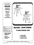
owner's
manual
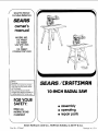
MODEL NO.
113.196221
113.196321
SAW WITH LEGS
or
113.196421
CONTRACTOR'S SAW
Serial
Number.
Model and serial numbers
may be found at the front
of the base.
You should record both
model and serial number in
a safe place for future use.
_'_E_A/F_S
/ I:RI1FT$ M RN
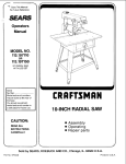
10-1NCH RADIAL SAW
FOR YOUR
SAFETY:
• assembly
• operating
• repair parts
READ ALL
INSTRUCTIONS
CAREFULLY
\
Sears Roebuck
Part No. SP5667
and Co., Hoffman
Estates, IL 60179
U.S.A.
Printed
in U.S.A.
Table of Contents
Section Title ................................................................................
Safety
Page
........................................................................................................................
Introduction
3
............................................................................................................
Assembly
12
................................................................................................................
Adjustments
............................................................................................................
19
...............................................................................................................
28
..................................................................................................................
37
Alignment
Controls
12
Electrical
Connections
Crosscutting
...........................................................................................
42
............................................................................................................
45
Ripping
...................................................................................................................
49
Cutting
Aides
58
Accessories
.............................................................................................................
61
...........................................................................................................
63
Maintenance
Troubleshooting
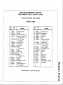
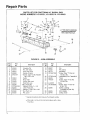
Repair
Parts
.........................................................................................................
.....................................................................................................
............................................................................................................
FULL ONE YEAR WARRANTY
If, this stationary
the date of purchase,
CENTER
IN THE
applies
ON CRAFTSMAN
tool fails due to a defect
year from
warranty
65
UNITED
only while
CONTACT
STATES
in material
THE
and Sears
this product
STATIONARY
or workmanship
NEAREST
will repair
is in the United
If this Radial Saw is used for commercial
or rental
apply for ninety days from the date of purchase.
70
SEARS
TOOL
within
one
SERVICE
it, free of charge.
This
States.
purposes,
this warranty
will
This warranty gives you specific legal rights, and you may also have other rights
which vary from state to state.
SEARS,
ROEBUCK
AND
CO.,
DEPT
817WA,
Hoffman
Estates,
IL 60179
U.S.A.
Safety
This manual
instructions
has safety
information
to help users
the risk of accidents
eliminate
and injuries,
and
M_or Hazards
or reduce
including:
i. Severe cuts, and loss of fingers or other
body parts due to contact with the blade.
2. Eye impact injuries, and blindness, from
being hit by a thrown workpiece, workpiece
chips or pieces of blade.
3. Bodily impact injuries, broken bones, and
internal organ damage from being hit by a
thrown workpiece
4. Shock or electrocution
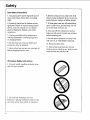
Three major hazards are associated with
using the radial arm saw for ripping. They
are outfeed zone hazard, kickback, and
wrong way feed.
This section only briefly explains these hazards. Read the ripping and crosscutting safety sections for more detailed explanations of
these and other hazards.
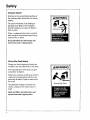
Outfeed Zone Hazard
5. Bums.
Ai_kDANGER
Safety Symbol
and Signal Words
An exclamation mark inside a triangle is the
safety alert symbol.
It is used to draw' attention to safety info_Tnation in the manual and on the saw. It is
followed by a signal word, DANGER,
WARNING, or CAUTION, which tells the
level of risk:
,_
DANGER: means if the safety information is not followed someone will be seriously injured or killed.
,_ WARNING:
means if the safety information is not followed someone could be
seriously injured or killed.
A
CAUTION:
means if the safety infor-
mation is not followed
inj are&
Fingers will be cut off.
Read and follow the information
A
,_
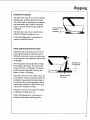
If you reach around the blade to the outfeed
side when ripping, and try to hold down or
pull the workpiece through to complete a
cut, the rotational force of the blade will pull
your hand back into the blade.
someone might be
Read and follow all safety information
and instructions.
instructions
under
ripping
safety.
and
Safety
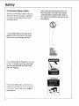
Kickback
Hazard
Kickback is the uncontrolled propelling of
the workpiece back toward the user during
ripping.
WARNING
The cause of kickback is the binding or
pinching of the blade in the workpiece.
Several conditions can cause the blade to
bind or pinch.
KICKBACKIII_
When a workpiece kicks back, it could hit
hard enough to cause internal organ injury,
broken bones, or death.
Read and follow the information
instructions
under ripping
and
safety.
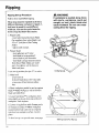
Wrong Way Feed Hazard
Wrong way feed is ripping by feeding the
workpiece into the outfeed side of the blade.
WARNING
The rotational force of the blade can grab
and pull the workpiece.
Before you can let go or pull back, the force
could pull your hand along with the workpiece into the blade. Fingers or hand could
be cut off.
Wrong Way Feed
The propelled workpiece could hit a bystander, causing severe impact injury or
death.
Read and follow the information
instructions
4
under ripping safety.
and
Safety
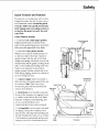
Guard
Function
The guard
designed
and Features
is a very important
to reduce
ated with blade
correctly.
feature,
the risk of injury associ-
contact.
Follow
in the ripping
safety
Install
the guard
the specific
instructions
and crosscutting
set and use the guard
sections
correctly
to
for each
ty pe of cut.
Guard Features Include:
1 A non-moveable
(Upper
Guard)
metal
which
motor by the guard
fully covers
clear
Guard)
Lower
ers the lower
plastic
most position
when
so the leading
contact
during
prevent
on the
teeth of the
It also protects
side of the
and acts as a barrier
to
way feed.
trigger
in the saw handle
raise the clear plastic
because
is in its rear-
is resting
with the outfced
wrong
of a crosscut.
cov-
It protects
and trailing
ripping,
3 A squeeze
rally
partially
blade
and the guard
blade are not exposed.
blade
and which
with the side of the blade
crosscutting
against
Handle!Squeeze
Trigger
to the
portion,
which
half of the blade.
contact
table,
is fastened
clamp screw,
(Plastic
during
portion,
the upper half of the blade.
2. A moveable
against
upper
Note:
guard
at the start
1"his' is necessary
the guard
Upper Guard
will not automatically
to be lowered
to just clear
the top of the workpiece
for ripping.
a_ a barrier
side of the blade,
to the infeed
keeps the workpiece
from fluttering,
acts as a sawdust deflector.
It is
locked/unlocked
by the hold down
5 A riving
knife
for ripping.
It keeps
Plastic Lower
Guard
Hold Down
Knob
raise to clear the fence.
4. A hold down
Pawls/Riving
Knife Knob
to
to be lowered
It acts
and
Riving
Knife
knob.
to the table
the workpiece
Pawls
kerf
open, thereby reducing blade pinching
and
the risk of kickback.
It also acts as a barrier
to the hazardous
wrong
outfeed
side and prevents
way feed. It is locked/unlocked
by
?
Hold
Down
Workpiece
Safety
the pawls/riving knife knob. When lowered
for crosscutting, it acts as a barrier to the
leading edge of the blade.
6. Set of pawls to be lowered to the workpiece surface for ripping. They allow the
workpiece to pass freely from infeed to outfeed side, but help stop the kickback motion
from ouffeed to infeed side by grabbing into
the workpiece surface. Pawls must be re-set
each time a different thickness workpiece is
Guard
Tab
cut.
7. A guard tab to manually raise the plastic
guard at the start of ripping unusual workpieces whose size/shape do not cause the
guard to raise automatically.
_CAUTION
Hazards Associated with Clear
Portion of Guard
The following safety information
all blades and accessories.
Clear plastic portion of guard can
get caught or jam in fence or table
kerfs. Read and follow the warning
on the guard:
applies to
WARNING
Clear plastic portion of guard will
not provide any protection
during
crosscutting
if blade is pulled over
your hand, or your hand enters
blade path from front or rear of
blade. Fingers or hand can be cut or
cut off.
,_WARNING:
TO AVOID INJURY
SHUT OFF POWER
BEFORE CLEARING
A
JAMMED LOWER GUARD
WARNING
Clear plastic guard will increase
• During rip and bevel cuts, narrow
cut-off
pieces
can be pinched
between guard and blade. Cut-off
pieces can kickback.
• In bevel position blade teeth are
fully exposed.
Fingers or hand can
be cut off.
risk of certain hazards:
• Cut off pieces can jam between
guard and blade. Turn saw off and
wait for blade to stop before freeing
jammed guard or blade.
• Workpiece
or cut-off pieces can
be violently thrown by blade. Wear
safety goggles. Stand out of workpiece path.
Safety
Safety Instructions
Read
and follow
all safety
instructions.
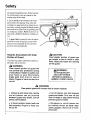
Personal Safety Instructions
1. Wear safety goggles labeled "ANSI
Z87.1" on the package. It means the goggles
meet impact standards set by the American
National Standards Institute. Regular eyeglasses are not safety goggles.
Safety Goggles
2. Wear close fitting clothes, short sleeved
shirts, and non-slip shoes. Tie up long hair.
Do not wear gloves, ties, jewelry, loose
clothing, or long sleeves. These can get
caught in the spinning blade mad pull body
parts into the blade.
3. Wear dust mask
to keep
Dust Mask
from inhaling
fine particles.
4. Wear ear protectors,
use saw daily.
plugs or muffs if you
5. Keep good footing and balance; do not
over-reach.
Ear Protectors
Work Area Safety Instructions
1. Keep children, pets, and visitors out of
work area; they could be hit by a thrown
workpiece, workpiece chips or pieces of
blade.
2. Turn
saw off, remove
unplug
before
leave
leaving
until blade
3. Make
work
yellow
work
has stopped
spinning.
area child-proof:
low key to prevent
accidental
key out of sight and reach;
key, and
area. Do not
remove
start-up;
yelstore
lock work area.
4. Keep floors clean and free of sawdust,
wax and other slippery materials.
5. Keep work area well lighted and uncluttered.
6. Use saw only in dry area. Do not use in
wet or danap areas.
\
\
\
Safety
Saw Safety Instructions
1. Use guard,
pawls
ing to instructions.
order.
and riving
Keep
knife
accord-
them in working
2. Routinely check saw for broken or damaged parts. Repair or replace damaged parts
before using saw. Check new or repaired
parts for alignment, binding, and correct
installation.
3. Unplug saw before doing maintenance,
making adjustments, correcting alignment,
or changing blades.
4. Do not force saw. Use saw, blades and
accessories
only as intended.
5. Have yellow key out and saw switched off
before plugging in power cord.
Workpiece
Safety
Instructions
1. Cut only wood, woodlike or plastic matefins. Do not cut metal.
2. Cut only one workpiece at a time.
Stacking or placing workpieces edge to edge
can cause user to lose control of workpiece.
6. Before turning on saw, clear table of all
objects except workpiece to be cut and necessary fixtures, clamps, or feather-boards.
7. If blade jams, turn saw off immediately,
remove yellow key, the free blade. Do not
try to free blade with saw on.
8. Turn saw off if it vibrates too much or
makes an odd sound. Correct any problem
before restarting saw.
9. Do not layout, assemble, or setup work
with saw on, or while blade is spinning.
10. Keep saw table clean.
11. Store items away from saw. Do not
climb on saw or stand on saw table to reach
items because saw can tip over.
Safety
3. Rip only workpieces longer than the
diameter of the blade. Do not rip workpieces
that are shorter than the diameter of the
blade being used.
4. Workpieces that extend beyond the saw
table can shift, twist, rise up from the table,
or fall as they are cut or afterwards. Support
workpiece with table extensions the same
height as the saw table.
5. To prevent tipping, support outer ends of
extensions with sturdy legs or an outrigger.
6. Do not use another person to help support
workpieces or to aid by pushing or pulling
on workpieces, because these actions can
cause kickback. Use table extensions.
7. Use clamps or vice to hold workpiece.
safer than using your hands.
Blade
Safety
It's
Instructions
1. Use only blades marked for at least 3450
rpm.
2. Use only 10" or smaller diameter
3. Use blades for their recommended
procedures.
4. Keep blade sharp and clean.
blades.
cutting
5. Do not overtighten blade nut because
blade collar could warp.
6. Do not turn saw on and off in rapid
sequence because blade can loosen.
7. Blade should stop within 15 seconds after
saw is switched off. ff blade takes longer, the
saw needs repair. Contact Sears Service
Center.
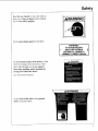
Safety
On-Product
Safety Labels
There are several safety labels on the saw.
They alert the user to hazards explained in
the manual and remind the user how to
avoid the hazard.
At the outfeed side, to the right of the
guard near the saw handle is this safety
label to alert you to wrong way feed:
Note where they are located on the saw.
Read and follow the safety information
and instructions in these labels. Refer to
the manual for detailed
instructions.
/
I
TO AVOID \\
INJURY DO \,.
NOT FEED \
MATERIALINTO \
I CUTTING
TOOL
On the infeed
ty label
down
piece
side of the guard
to remind
to just
you to lower
clear
is this sdethe hold
the top of the work-
for ripping:
_DANGER
On the rear
infeed
side when
is this safety
zone hazard:
10
of the yoke,
visible
from the
the saw is in a rip position,
label to alert you to outfeed
explanations
and
Safety
Near
the saw handle
"alert you to thrown
you to wear
On the clear
is dais safety
objects
safety
label to
,&WARNING
and to remind
goggles:
plastic
guard
is this label:
=
On the bottom
surface
of the motor, visible
TO AVOID INJURY
SHUT OFF POWER
BEFORE
CLEANING A
WARNING:
JAMMED LOWER GUARD
!
I
,,
DANGER
when the cutting tool is horizontal, is this
safety label alerting you to use a guard
when edge molding, and to position the
culling tool behind the fence:
(see Accessories
Section)
,_WARNING
On the front of the yoke is dais general
safety instruction label:
11
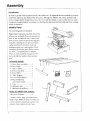
Assembly
Introduction
In order
to get the most enjoyment
assembled,
hours
adjusted,
or longer
out of your radial saw it is important
and aligned.
This procedure,
for the inexperienced
completed
in approximately
which are incorrect.
although
user. However,
ten minutes
not difficult,
that the machine
takes time; perhaps
after this initial set-up
by checking
the alignment
a weekly
and only adjusting
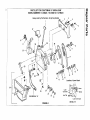
Identify Parts
The following
Note:
part,
Sears
parts are included:
Before
all parts
beginning
are included.
do not assemble
Service
Sometimes
check
that
If you are missing
assembly,
any
the saw Contact
Center
aghzg material
can get lost in pack-
Do not throw away arty
packagi,g
until saw is put together.
pacl_zgh_g
for missh_g parts
ing Sears. A complete
Parts)
your
to get the missing part.
small parts
parts
contact-
list (Repair
is at the end of the manual.
list to identify
the number
Check
before
Use the
of the missing
part.
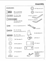
All models
include:
A. Basic Saw Assembly
......... 1
B. Rear Table ..........................
1
B
C
D
F
C. Spacer
Table
......................
1
D. Fence (wooden)
.................
E. Front Table ........................
1
1
F. Table
Support
2
G. Loose
Parts
....................
Bag(s)
............
*
H. Bag Containing
Accessory
J.
Guard
...............
Leg .....................................
K. Stiffener,
Side ....................
L. Stiffener,
Front!Rear
Model 113.196421
1
4
2
d
.......... 2
Only includes:
K
M. Lower Stiffener .................. 4
* Number
smaller
varies;
er keep contents
separate
_2
bags can contain
bags. Note:
To make
other
assembly
easi-
of each bag tog_¢ther and
from contents
of other
bags.
by properly
L
eight
tune-up
can be
those
settings
Assembly
All models
include:
5/16" diam.
5/16" - 18 x 3/4" long
square head screw (4)
1/4" diam.
hex nut (4)
hex nut (4)
_llqqillllll[tllllliO
1/4"-20x
1"long(4)
pan
head screw
1/4" hex "_
_ IillJllilll_liH_l_l_lilllllil,lt_
1/4" - 20 x 1-3/4" long
3/16"
hex "L'_
pan head screw (1)
#6 - 32 x 1/2 pan head screw (4)
wrench (2)
_lllllllllll)
#10 - 32 x 7/8" long
pan head self threading
screw (2)
rip scale indicator
1/4" - 20 x 1" long
_illllllllltlllllil7
slotted cup point set screw
(2)
(1)
yellow key (1)
17/64" fiat washer (5)
©
©
©
1/4"U-clip
5/16" flat washer (4)
5/16" lockwasher
1/4" lockwasher
tee nut (1)
(4)
(4)
i
--6"
]
(1)
twin nut (2)
table clamp assembly
- thumbscrew
(2)
- square nut
- clamp bracket
- cup washer
13
Assembly
crank
arm cap
©
1/4" diam. x 5/8" long
truss head screw (24)
(40 for 113.196421)
@
leveling foot (4)
C)
3/8" diatn, hex nut (8)
@
5/16" diam. hex nut
@
1/4" external tooth
lockwasher (24)
(40 for 113.196421)
5/16" diam. external
lockwasher
(4)
11/32" x 11/16" x 1/16"
washer (8)
(4)
©
5/16" diam. x 5/8" long
hex head screw (4)
1/4" diam. hex nut
(24)
(40 for 113.196421)
Tools needed
for Assembly
and Alignment
7116" Wrench
@'
_
1,'2" Wrench
Wrench
@
........
@
9/16"Wrench
Medium
15/16"
Screwdriver
Wrench
Pliers
Phillips
Screwdriver
Framing
Small
Hammer
Pencil
14
I
Square
Assembly
_k WARNING
Plugging
in saw during assembly
could result in electrical shock, or
severe cuts from contact with spinning blade.
Do not plug in saw at any time during assembly.
Plug in saw only when it is to be
used.
Assembly
Steps
It is important for your safety and to get
accurate cuts that you put the saw together
according to these instructions.
Fol!ow these steps in order.
Assembling
steel legs
For easy assembly it is recommended to finger tighten all screws, lockwashers, and hex
nuts until the legset is fully assembled. Then
go back and tighten all nuts securely.
From among the loose parts, find the following Hardware:
24 Truss Head Screws, 1/4-20 x 5/8
24 Lockwashers,
1/4-External
24 Hex Nuts, !/4-20
8 Hex Nuts, 3/8 - 16
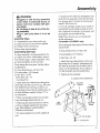
5. Install one 3/8-16 hex nut completely onto
each of the leveling feet. Insert one leveling
foot through hole in bottom of each leg and
install a 3/8-16 hex nut.
6. To level steel legs, loosen nut on inside of
leg and turn nut on outside to raise or lower
feet. Adjust all four levelers if necessary, and
then tighten nuts on inside of leg.
Note: These levelers" are not intended for
height adjustment.
For model 113.196421
From among the loose parts, find the following hardware:
16 Truss Head Screws
16 Lockwashers,
1/4-20 x 5/8
1/4" external
16 Hex Nuts, 1/4 -20
!. Attach the lower leg stifeners to the steel
legs using two (2) screws, lockwasher and
hex nuts on each end. For the short side of
stand, use the inside holes in the stiffeners.
For the long side, use the outside holes.
2. Tighten all nuts securely.
X = Location of Truss Head Screws
4 Leveling Feet
1. Insert three truss head screws through the
three holes near the top of one Leg. Place the
Side Stiffener up to the Leg, as shown, so
that the three screws line up with the holes in
the Side Stiffeners marked with an "X" in
the illustration.
2. Place a lockwasher
only
Front/Rear
Stiffener
and hex nut on each
screw and finger tighten the hex nut.
3. Following the same procedure as above,
continue to fasten together the remaining
Side
Stiffener
Truss Head
Screws
Legs, Side Stiffeners, and Front/Rear
Stiffeners as illustrated.
4. Set stand upright and securely tighten all
nuts.
3/8" Hex Nuts
Leveling Foot
15
Assembly
Leg
Mounting
Saw
/
1. From _mlong tile loose p'-w'ts,find the fol-lowing hmdware:
4 ttex
tlead
Screws,
4 Lockwasher,
8 Washers,
5/16-18
Leg
,
,/
%,
//
x 5/8
5/16 in. External
Type
11/32 ID
4 Hex Jam Nuts, 5/16-t8
2. Place saw on legs so that holes in bottom
of saw line up with holes marked X in top of
legs.
3. Install screws, washers and nuts as shown.
If you mount the saw on any other
Craftsman base or Slat bench, make sure
Elevation Crm_k has proper clearance to
rotate. The saw must be bolted down.
Position saw to slope slightly rearward, so
when tile carriage is installed it will not roll
forward due to gravity.
SawBase
Hex Head
_
I
Stiffener
Flat Washer
Front
/
Sliffener
_WARNING
Saw must slant slightly
towards
rear to keep blade carriage
from
rolling
forward.
Workpiece
or saw
can move unexpectedly
if leg set
rocks. Fingers,
hand or arm could
be cut off by blade contact. Adjust
leveling feet before using saw.
Lockwasher
Hex Nut
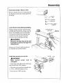
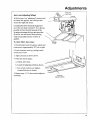
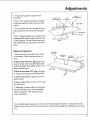
Attach
Elevation
Crank.
Install crank on elevation
setscrew
shaft. Be sure
is tightened on flat of shaft.
Shipping
Block
Elevation
Crank
(Turn clockwise
to raise arm)
\
\
Elevate
arm approximately
3 to 4 inches.
Remove shipping block mid discurd.
16
\
\
Assembly
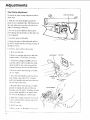
Attaching Carriage
- Motor to Arm
Remove carriage stop screw, lockwasher and
tag. Read and understand warning tag before
discarding.
Warning
Tab
(_j_
Lockwasher
_,.......,._-_
_
Stop Screw
"'-'- Hex "L" Wrench
(Supplied)
Lock miter/arm lock before proceeding.
Holding carriage assembly with both hands,
carefully start and slide the carriage onto the
tracks. The assembly must be held parallel
with the arm so that all four bearings slide
smoothly onto the arm, preventing any
excessive strain on bearings and track.
Push toward rear of
saw to lock
Miter/Arm
Lever
WARNING
Reinstall carriage stop screw and
Iockwasher to prevent carriage from
rolling off arm.
Remove two (2) motor packing studs that
are threaded into bottom of motor.
Arm Cap
Install arm cap and arm cap trim
Screw
,_WARNING
Make
certain
unplugged.
power
cord
is
1 Insert finger under left end of switch lever
and pull out to the "ON" position.
2 Place arm cap in position and install with
(2) 10-32 x 7/8 self threading screws.
3. Push switch to "OFF" position.
17
Assembly
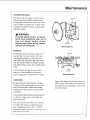
Remove
saw blade.
1. Tighten carriage lock knob, located on
right side of ann.
2. Loosen guard clamp screw approximately
4 turns.
3. Use one hand to lift the clear plastic guard
at the front of the saw.
Purl down
to |oo_er}
Blade
Rotation
4. Use the other hand to grasp the rear of the
guard (below the dust elbow).
5. Rotate the entire guard assembly
approximately
45 °.
forward
6. Remove the guard assembly.
7. Motor shaft has left hand threads. Hold
shaft wrench and rotate arbor wrench down
(clockwise).
8. Remove shaft nut, outer collar, saw blade,
and inner collar. Set aside and out of the
way.
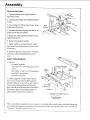
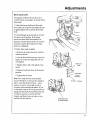
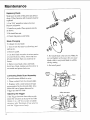
Attach Table Supports
1. Set out:
- two table supports
- four 5/16" 18 x 3/4" long square head
screws
- four 11/32" x 7/8" x 1/16" flatwashers
- four 5/16" lockwashers
- four 5/16" hex nuts
Table
Table
Support
Support
\
SCreWS
2. Attach supports to side frame, making
sure to use correct holes in table supports
and side frame: Use two screws per support
(insert screws through base and then support); on end of each screw put a flat washer,
lockwasher and nut then finger tighten so
table supports rest in lowest position.
Here
Nut ""_
Lockwasher
Flatwasher
Base
_]
Mount
rails
Front
using
these holes
This concl_tdes
saw should
"looseness"
18
the assembly
be completely
in order
section.
assembled.
to get accurate
Except
for installing
The next section
cuts.
table bonds,
fence,
deals with adjusting
and table clamps
the
your saw to remove
'all
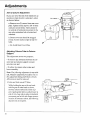
Adjustments
Miter/Arm
Arm Lock Adjusting
Lock
Wheel
Lever
With the arm at an "unindexed" position and
the miter lock applied, the locking action
should feel tight and secure.
Considerable
move
effort
the ann back
should
be required
towards
to
0 °. Its is "always
possible
to force the arm because
leverage
advantage
of the
the long arm provides.
However,
the arm should resist moving
when a reasonable
amount of force is
applied.
To check
follow
these steps:
1. Pull miter/arm lock forward to unlock and
rotate ann to approximately 30° left or right.
2. Lock miter/arm lock by pushfng handle
toward rear of saw.
3. Apply pressure as shown above.
4. If the arm moves easily:
a. Unlock miter lock.
b. Locate the adjusting wheel as shown.
c. Turn wheel clockwise to tighten,
counterclockwise to loosen.
5 Repeat steps 1, 2, 3 above and readjust as
necessary.
Arm Lock
Adjusting Wheel
19
Adjustments
Yoke Clamp
Adjustment
To check the yoke clamp adjustment
these steps:
Yoke Lock Handle
follow
1. Pull the yoke lock handle towards the
front of saw to unlock yoke. Pull forward on
the yoke index lever (on the left side of carriage) to disengage index pin.
2. Swivel the motor halfway between the
crosscutting and rip position so the index pin
is not engaged.
3. Lock the yoke lock handle.
4. Grasp
the motor
with both hands
to swivel it back into the crosscut
should not move.
5_
If it does move
a. Rein,we
tbllow
and try
position.
It
these steps:
arm cap.
Lock Washer
b. Remove carriage stop screw and lockwasher with a 1/4 inch hex-L wrench.
Arm Cap
c. Grasp the carriage assembly,
move it
careful] v off the end of radial ann, holdScrew
ing it parallel
carriage
to the radial
bearings
arm until all
are free of their tracks.
d. Rest lhe motor
on saw frame.
and carriage
assembly
e. Set yoke lock handle at unlocked position. Tighten nut with 15/16" x_,renctl,
until lock handle locks mid-way between
Carriage Stop
Screw
Hex "L" Wrench
(1i44nch)
the two legs of the yoke.
f. ltold the motor and carriage assembly
parallel to radial arm and starl the rear
bearings onto the tracks. Continue to hold
the assembly parallel to the tracks unlil
the forward bearings are on the tracks.
g. Slide the carriage
rearward
the carriage
a[ arn-t tmlld install
15/16"
on the radi
stop screw
and lockwashcr.
h. Instal!
arm cap.
i. Rcpcul
steps
I
2O
1 4. Read usl if nccc_<s',try.
Wrench
/
/
Adjustments
Bevel Lock Lever
l
1
©
The purpose of the bevel lock lever is to
lock the motor at any angle. To check follow
these steps:
Bevel
Index
1. Unlock the bevel lock lever. Move the,
Pin
bevel index pin to the left and rotate the saw
to approximately 30 °. Lock the bevel lock
lever.
2. Use both hands as shown and try to force
the motor out of position. If the motor
moves, the bevel lock lever needs to be
Bevel
Lock
Lever
tightened. On the other hand if it is extremely hard to lock the bevel lock lever it has
been over -tightened.
3. Follow these steps to adjust:
a. Remove the socket set screw with hex
wrench as shown.
\
b. Use the bevel lock lever as a wrench to
tighten or loosen the clamp bolt. Do not
over tighten.
[_
c. Repeat steps 1 and 2. Re-adjust
essary
d. Replace
bevel
lock lever
Bevel Lock
if necLever
in the locked
position.
Lockwasher
e. Tighten the set screw.
Note:
The clamp
thread.
effect,
bolt has a left handed
Therefore,
rotate
to increase
the bevel
used as a wrench
clockwise
when
accidentally
engage
-from
rotate
it will be necessary
1/8" Hex "C" Wrench
lock lever - when
viewed
the bolt from
the clamping
right to left, or
from
above.
it the wrong
way and dis-
the matching
to remove
If you
steel nut,
the Yoke
Handle, and Bevel Scale, in order
stall the bolt into the nut.
to rein-
\
Bevel Lock Lever
In Locked
Position
21
Adjustments
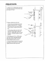
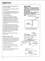
Arm to Column Adjustment
If you can move the end of the radial arm up
and down when the ann is unlocked, adjust
as directed below:
a. Remove
3/8-16
Bolts
two (2) screws from rear cover
plate. Tighten evenly top two 3/8-16 bolts
until arm moves firmly. There should be
no vertical or horizontal movement in the
arm when miter/arm lock is locked and
unlocked.
b. Bottom two nuts should be snugged
evenly, but not nearly as tight as top two
bolts.
c. Re-Install
Rear Cover Plate.
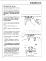
Adjusting Column Tube in Column
Support
This adjustment serves two purposes;
• To remove any looseness between the column tube and column support to insure
accurate cuts; and
• To allow the column tube to raise and
lower smoothly.
Note: The following adjustment is very critical All future alignment procedures rely on
this adjustment being performed correctly.
All looseness must be removed.
1. Index
and lock arm at 0 ° Miter.
While holding the arm with one hmad,
hold fingers of other hand as shown,
between column tube and column support. Apply gentle side-to-side pressure at
end of arm. Any side-to-side or rotational
movement can be felt with finger at arrow
location. If looseness exists, the following
adjustments are required.
22
3/8-16 Nuts
Adjustments
2. lax)sen (2) 1/4 - 20 Gib socket cap screws
on the left side at the rear of the column support slightly (1/2 turn).
Front
Hex "L" Wrench
_
_
(Supplied)
1_
I
"_
3. Elevate, and then lower the Ann:
a. If the column tube binds and elevation
is difficult, loosen two 5/16 - 18 plated
bolts on front side of the column support
until you achieve smooth but firm elevation.
b. If the column tube moves side-to-side
Front
5
1
J
/
t
Bright Plated
Bolts
within the column support, tighten the
two 5/16 - 18 plated bolts until movement
disappears - elevation should be smooth
and firm.
4. Now tighten the (2) 1/4 - 20 Gib socket
cap screws until no noticeable rotational
play exists between Column Tube and
Column Support as shown in step 1.
©
5. Turn the elevation handwheel to raise and
lower the saw. If movement is too difficult
slightly loosen the socket cap screws.
23
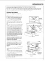
Adjustments
Adjusting
Carriage
Bearings
ff the carriage bearings are loose it not only
allows the saw blade to move up, down, and
sideways but also results in inaccurate cuts.
Before following these steps make sure the
tracks (steel rods) and carriage bearings have
been cleaned by wiping them with a clean
cloth.
When properly adjusted, the top and bottom
face of all four bearing grooves should be in
contact with the arm tracks for their entire
length and carriage should roll smoothly
with some resistance.
To test for looseness between bearings and
tracks on radial arm, perform the following
steps.
1. Remove
left-hand carriage cover. (2
screws)
2. Push the carriage to its full rearward position.
3. Grasp front carriage bearing as shown and
hold as tight as possible. At the same time
pull carriage forward. If you can stop the
bearing from turning, it requires adjusting.
4. Check rear bearing in the same manner.
5. Adjust
as follows:
a. Use two 1/2" wrenches
to loosen nut
just enough to permit the eccentric screw
to turn.
b. Rotate the eccentric screw a partial turn
Oefl or right) as required to take up looseness.
c. Hold
the head
of eccentric
screw
in the
in the preceding
step
Washer
Eccentric
Screw
Assembly
Carriage
position
established
and tighten
Correct
nut on underside
adjustment
exists
of carriage.
when
not keep
the bearings
from
However,
excessive
bearing
Carriage
Bearing
you can-
turning.
pressure
will
Plain
Washer
cause
difficult
d. Install
24
operation
carriage
cove1;
Loekwasher
and rapid wear.
Nut
Left
Side
Carriage
Bearings
Adjustments
Positioning
Table Supports!Installing
Front Table/Leveling
Front Table
Note: The goal in aztjusting the table supports and leveling the front table is to make sure that the
table is the same distance from the radial arm at all points. This ensures that when the table and
blade are installed the clearance between them will be equal at all points.
Positioning
Table Supports
1. Release bevel lock lever, move bevel
index lever to the left and rotate the motor to
position arbor shaft down. Lock bevel lock.
2. Unlock and hold nfiter/arm
lock lever in
Index Release
Position
Unlock
Miter!Arm
Lock Handle
index release position as shown. Position
arm against left stop (approximately 50 °
miter). Loosen carriage lock knob and position arbor shaft directly over left hand channel.
Note: For safety reasons in accordance with
the UL standard, stops have been provided
to prevent 360 ° rotation of the radial arm.
BevelLock
Lever
3. Slide the arbor wrench handle between
end of motor shaft and table support to act as
a feeler gauge. Carefully lower the motor
with elevation crank until the end of shaft is
just touching the arbor wrench. The wrench
should slide back and forth with only slight
resistance. Tighten screw "'A".
Arbor Wrench
Screw "A"
Note:
Do not change
until both left
this elevation
and right hand table support
channels
have been
4, Move
arm and carriage
Adjust
arbor
position
wrench
setting
adjusted.
of table
to screw
"B".
support
so that the
just slips between
the end of
the motor shaft and the support.
screw "B".
Tighten
5. Move arm and carriage to right hand table
support and level in the same manner as in
step 4.
6. Recheck both support channels to make
sure that tightening screws did not affect the
accuracy of the adjustment.
7. Elevate saw and return motor to horizontal position to provide clearance
tion of front work table.
for installa-
Arbor W_,_._
_l-_-'"
/
__
//J
YScre/w
Table Mounting
Support
j/
"B"
(Left
Channel
Hand)
Screw "A"
25
Adjustments
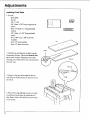
Installing
Front Table
1. Set out:
- front table
- tee nut
- 1/4" U-clip
- 1/4" diam. x 7/8" long cup point set
screw
- four 1/4" diam x 1" long pan head
screws
- 1/4" diam. x 1-3/4" long pan head
screw
- five 17/64" I.D. x 5/8" O.D. flat
washers
- four l/4" lock washers
- four 1/4" diam. hex nuts.
T-Nut
2. Identify top and bottom of table: top has
counterbored holes. Place table bottom side
up on solid surface. Hammer tee nut into
leveling hole. (This hole is not counter-bored
from the top).
3. Snap U-clip onto front edge of base so
hole lines up with hole just to the left of center notch.
4. Place table, top side up, on saw so center
counterbored hole lines up with hole in Uclip. Note: Table will extend over front edge
of saw frame.
26
Adjustments
5. Drop a flat washer into each counterbored hole.
1/4-20 x 1"
Pan Head Screw
1 ;4-20 x |-3/4"
17164"
Pan Head Screw
Flat Washer
6. Start 1-3/4" long pan head screw through
center hole and into U-clip, but do not fully
_Front
Table
tighten.
7. Start cup point set screw through leveling
hole and into tee nut, but do not fully tighten.
Hex Nut
8. Put 1" long pan head screw in each of four
remaining holes and through matching holes
in table supports. On end of each screw, put
lock washer then nut and tighten with screwdriver.
Make Front Table Flat
1. Place rear table on its edge, across center
of front table. Check for gap between surfaces.
1/4-20 x 7/8" Cup Point Set
Screw
Rear Table
Board
_ _Hold
Down
Screw
Leveling
Set Screw
]
j
If there is less than 1/32" gap, tighten cup
point set screw until it touches frame (look
underneath table), then tighten center (1-3/4"
long) pan head screw.
If there is more than 1/32" gap, close gap
by raising or lowering center of front table:
to raise center, tighten cup point set screw
against frame;
to lower center, tighten center (1-3/4" long)
pan head screw.
2. When gap is closed, make sure cup point
set screw touches frame (look underneath
table), and center (1-3/4" long) pan head
screw is tightened.
This concludes adjusting your saw where you have removed "all"looseness" or slack between the
different parts of the saw. The next section deals with actually aligning the sawblade to get accurate
cuts.
27
Alignment
This section applies to all three models covered by this manual.
The saw and blade
for two reasons:
must be aligned
correctly
1) to prevent binding of the blade and workpiece, which can cause jams, kickbacks, or
thrown workpieces;
2) to make accurate cuts.
Alignment
and Adjustment
,_WARNING
Plugging in saw during alignment
could result in accidental
start-up
and severe cuts from contact with
spinning blade.
Do not plug in saw at anytime during alignment or adjustment.
Plug in saw only when it is to be
used.
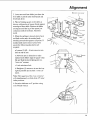
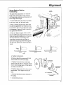
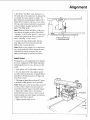
Check Framlng Square
Steps
This edge must
be straight
The following alignments and adjustments
must be made in order. If you miss an
adjustment, you must go back, make the
missed adjustment, and repeat all steps from
that point on.
These adjustments are like fine tuning a
piece of equipment. Often, a series of steps
must be repeated more than once in order to
get the adjustment right. There are many
adjustments to make. Because some adjustments may be awkward, you may want to
ask someone to help you.
Before you start, make sure the framing
square is true.
Square Crosscut
/
II
I
I
I
Draw light
line
on board
f
along this edge
L:
/
Should be no gap or overlap here when
square is flipped over to dotted position.
Blade
Rotation
Travel
The goal of this adjustment is to make accurate crosscuts. To do so, the radial arm must
be square to the fence, otherwise, there will
be a slight miter angle in all crosscuts.
Squaring
cross cut travel.
k_
_
o
//
End of arbor wrench
resting on table
1. Index but do not lock arm at 0 ° miter.
2. Install saw blade as shown. Motor shaft
has left hand threads.
1_fff_
Saw
Note: Do ru-)tovertighten arbor nut. Use the
arbor wrench to just "snug" it.
Blade _/_
Outor/
Collar
28
(;__i
li
\
,hoot
Motor
Collar
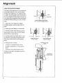
Alignment
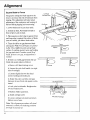
Miter,
Arm
Lock
Lever
3. Lower arm until saw blade just clears the
front table. Lock the yoke lock handle and
bevel lock lever.
4. Place a framing square on the table, as
shown, with one leg of square t-manly against
rear edge of front table. Position the blade
and square until the leg of the square just
contacts a tooth of the blade. Mark this
tooth.
5. When the carriage is moved slowly back
and forth on the arm, the marked tooth
should just touch the square at NI points. If
marked tooth moves into or away from
square the following adjustments are
required:
(
Yoke
Lock
Handle
'Bevel Lock
Lever
Tooth
a. Loosen (3) 3/8 - 16 set screws in arm
latch at rear of arm.
b. Move the arm in direction to make
marked tooth follow edge of square when
the saw blade is moved "alongarm in a
"cross cut" manner.
c. Lock miter/arm
d. Retighten
Note:
lock.
(3) setscrews
fight as possible
travel.
This squaring
will simultaneously
3,'16" Hex "L" Wrench
(Supplied)
in ann latch as
and recheck
"cross
cut"
of the cross cut travel
set both of the 45 ° miter
index positions.
6. Set miter indicator on 0° position using
end of blade wrench.
29
Ali nment
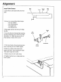
Install Table Clamps
Front
Table
1. Insert fence, then spacer table, then rear
table.
Fence
Spacer
Table
Rear
Table
\
L
2. Set out two unassembled table clamps:
- two cup washers
- two clamp brackets
- two square nuts
- two thumbscrews
3. Slip square nut into slot at top of clamp
bracket.
Square
Nut
4. Insert thumbscrew through rear opening,
and turn c!ockwise until it comes out other
side about 1/2". Note: If you put screw in
front opening, clamp will not work.
waCshPr
.__
Thumbscrew
5. Tilt clamp bracket forward and snap into
place in opening at rear of table support.
6. Hold cup washer with concave side
against rear table. Turn thumbscrew clockwise until it snaps into washer.
7. Repeat steps for other table clamp.
8. Tighten thumbscrews
tions in place.
3O
to clamp table sec-
Clamp
Bracket
Alignment
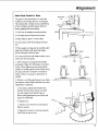
Square Blade to Table for
Crosscutting
Bevel
Indicator
The goal of this adjustment is to make the
blade square to the table so that crosscuts
will be accurate; otherwise all crosscuts will
have a slight bevel angle.
1. Lower blade until it just dears front table.
Lock bevel, miter, rip, and yoke locks.
2. Place a framing square on the table with
the short leg against the saw blade and long
leg parallel to fence. Do not allow the square
to rest against a "set-out" tooth; it must rest
flat against the blade side.
Rip
Fence
3. If the saw blade is square with the table
top (no visible gap appears between the saw
blade and square) no adjustment is required.
Set bevel indicator to 0 ° reading. If the
square does not touch the saw blade as
shown (with square leg held firmly against
the table top), perform the following adjustments:
SquareN
I
Square
(Place parallel
to fence)
_!
I
I
Correct
/
Table
!
I
I
I
Wrong
I
Wrong
a. Tighten rip lock knob.
b. Remove handle by removing 5/16-18
socket head screw and lockwasher.
c. Slightly loosen the four socket head
screws with 1/4" Hex "L" Wrench. Rotate
motor
while
holding
square
saw blade
and table top.
d. Slightly
tighten
and recheck...Now
fn'rnly
each of the four screws
tighten
@--'_Jt_
each screw
tight.
e. Reinstall
/HeadScrew
5/16" Lockwasher
handle
and adjust
indicator
to
_'_'_
1.;4" Hex "L" Wrench "_'_
(Supplied)
0 ° reading.
f. Loosen
,(til
against
rip lock knob.
31
Alignment
Square
Blade to Fence
Left Hand
Carriage Cover
The goal in setting the blade square to the
fence is to reduce the risk of kickback when
ripping. This adjustment will also reduce
splintering of the workpiece and buming of
the keff during ripping and crosscutting.
I
Rip Fence
1. Lower blade until it just clears table.
2. Unlock
front
rip lock, Pull blade
forward
to
of arm. Lock rip lock.
3. Place square so short edge is against fence
and long edge is against fiat surface of blade
(not on a tooth), just below blade collar.
4. There
should
and square.
ty flat.
Check
surface
be no gap between
blade
Not all blades
are perfect-
Note:
different
by making
points
along
Fence
blade
quarter
turns and looking
Consider
overall fit of
for gap each time.
I
blade. If there is no gap, no adjustment
needed.
Square
]_
is
I
I
1
I
5. If there is a visible gap between the saw
blade and square adjust as follows:
a. Remove left hand carriage cover.
b. Loosen the yoke lock handle. (on right
side of carriage).
c. Loosen slightly the two hex-head
screws holding yoke index pin.
d. Rotate the yoke assembly until gap
between the saw blade and square is eliminated.
e. Lock yoke lock handle. Retighten
two hex-head screws.
Hex Head
Screws
the
f. Recheck blade squareness.
g. Install carriage cover.
Left side of Carriage
h. Loosen carriage lock knob and return
blade to rear of arm.
Note:
32
This alignment
procedure
taneously
set both yoke
for blade
in and out rip.
indexing
will simulpositions
Ali, nment
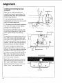
Make Blade Parallel to Table
The goal of this adjustment is to keep the
workpiece from being thrown or damaged.
This adjustment will also reduce splintering
of the workpiece and burning of the kerr
during ripping and crosscutting.
1. Lock arm in straight crosscut position.
2. Pull blade forward and lock rip lock.
3. Raise blade at least 2" above table.
4. Lock motor at 90 ° bevel (blade horizontal).
Correct
5. Place square so long side is on table under
right side of blade, and short side hangs
down vertically at front of saw.
Blade
6. Lower radial ann until blade surface, not a
tooth, just rests on square.
7. There should be no gap between blade
and square. Note: Not all blades are perfectly flat. Check different points along blade
surface by making quarter turns and looking
for gap each time. Consider overall fit of
blade. If there is no gap, no adjustment is
needed.
Square
Table
Wrong
Wrong
8. If there is a visible gap between saw blade
andsquare, a bevel heel condition exists and
adjustment is required.
a. To correct, unlock bevel lock lever.
Loosen the rear motor mount nut until
you can rotate Cam. Rotate Cam as
shown until gap between saw blade and
square is eliminated.
b. Tighten nut.
c. Tighten bevel lock lever and recheck
blade to square.
d. Reposition motor to crosscut position
with blade at rear of arm.
33
Alignment
Installing and Adjusting Rip Scale
Indicators.
Note: The rip scales and pointers are
intended to be used for quick settings. For
greater accuracy, take direct measurement
between blade and fence.
Screw
#6-32
_[_Jl'_,
I
1. Pre-assemble indicator and twin nut.
Loosen but do not remove two screws which
x 1/2
Rip Scale
lndicator
attach left hand carriage cover.
2. Tilt carriage cover and install rip indicator
with twin nut on inside of cover. Tighten
carriage cover attaching screws.
Twin Nut
3. Loosen but do not remove rip lock knob
in right hand carriage cover. Install rip indicator. Tighten carriage cover attaching
screws.
4. With
fence
front table),
in its normal
loosen
position
Yoke Index Lever
Yoke Lock Handle
(next to
yoke lock handle,
pull
yoke index lever forward and rotate yoke to
the left to index yoke 90 ° from the cross cut
position.
motor
This will locate
and fence.
5. Position
when
Lock
carriage
hand side of radial
scale.
If not, loosen
the indicator
then tighten
Note:
With saw blade
tion shown,
Rip"
scale
extreme
blade
now read
screws
and shift
with the "0"
and fence
portion
Iffence
rear position,
"In-Rip"
[
Table Spacer Board
Rip Scale Indicator
the screws.
the upper
is used.
Table
scale
in the posi-
of blade
is moved
"In-
to
the lower portion
of
would be used.
O
Rip
Lock
34
I
of the blade "In-
until it is aligned
mark,
front face
(on the fight
should
portion
/
Fence
of blade,
indicator
arm)
on upper
Table
Front
between
lock handle.
just touches
The rip-scale
"0" inches
Rip"
yoke
until edge
spun by hand,
of fence.
saw blade
Knob
r] _
Alignment
6. The blade "Oul-Rip'"
scale indicator on
left hand side of the radial arm is adjusled in
essentially
the same manner as blade "InRip" indicator,
inches between
except position blade with 2
fence and face of saw blade.
I
J
The rip-scale indicator should be positioned
to read 2 inches on upper portion of the
blade "Out-Rip"
scale.
Note: With saw blade and fence in the position shown, the upper portion of the blade
'Out-Rip"
scale is used. If fence is moved to
e_rtreme rear position the lower portion
blade "Out-Rip"
scale is used.
of
2"-Measured from fence
to nearest blade tooth
I
J
7. Loosen the yoke lock handle, pull the
yoke index lever forward and return the
blade to the crosscut position.
Note: Blade is now aligned. It is important
that you periodically
check alignment
and
adjustment
to insure accurate
cuts and
improve and safety of cutting procedures.
Install Guard
The guard is a very important
safety feature.
It covers a large part of the blade and helps
protect
guard.
against
I. Lock motor
severe
cuts. Always
at 0 ° bevel
(blade
use the
vertical).
2. Use one hand to lift clear plastic guard;
use other hand to grasp rear of guard (below
dust elbow). Position guard so riving knife
laces front of saw.
3. Tilt front of guard down about 45°; place
over blade; rotate guard to level position.
Note: Make sure notc'h in guard fits onto tab
on motor. This will prevent movement of
guard about motor. Squeeze handle trigger
to make sure it fully raises clear plastic
guard. If it does not, remove and re-install
,_,uard, making sure that trigger
engages pull link on guard.
4. Tighten
guard clamp
mechanism
screw.
Parallel
35
Alignment
Align Riving Knife to Blade
The goal of this adjustment is to position the
riving knife directly in line with the blade.
Riving knife alignment is an important safety factor. The riving knife rides in the kerf of
the cut workpiece during ripping to keep the
two sides of the workpiece from pinching on
the blade. Blade pinching is a cause of kickback.
Fence_
_
Riving
PawlsKnife
Correct: Blade and Riving Knife
are in Line and Flat Against Fence.
1. Lock yoke in in-rip position (blade
towards column, motor towards front of
arin).
2. Lower
3. Unlock
plastic
touches
arm
until blade just clears
rip lock while
guard,
fence.
move
Lock
holding
yoke back
table.
up lower
until blade
rip lock.
4. Loosen pawls/riving knife knob. Lower
riving knife to the table and tighten knob.
The riving knife should rest flat against
fence.
5. If adjustment
is needed:
Wrong: Riving Knife
on Top of Fence.
Wrong: Riving Knife
Away from Fence.
Pawls/Riving
Knob
Knife
i) loosen riving knife bracket screw.
ii) slide riving knife so it rests ag_finst
fence.
iii) secure riving knife bracket screw.
6. Raise riving knife and tighten pawls/riving knife knob.
Riving Knife
Bracket Screw
36
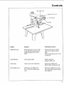
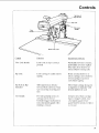
Controls
Bevel Index Lever
r Lock
Lever
Yellow Key
Function
Operation/Comments
Frees radial ann to move; locks
in any desired position; pre-set
indexed positions at 0 °, 45°L,
45°R
Pull lever forward to release
index then swing ann left or
right
Hold in unlocked position while
moving arm
On-Off Switch
Turns motor on/off
Pull on, push off
Requires yellow key
Yellow Key
Allows saw to be switched on
Insert into on-off switch
Remove after turning saw off
Bevel Index Lever
Indexes the saw blade to 0°,
45 °, or 90 ° pre-set index positions
Move bevel index lever to the
Control
_ter/Arm
Lock
left while positioning
then release it
the blade,
37
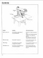
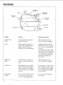
Controls
Yoke Index
Lever
Table Clamp
Bevel
Elevation
Con_ol
BevelLock
Lever
Lock Lever
Crank
\
Function
Operation/Comments
Frees motor to rotate; locks in
any desired position
Pull lever
lock
to release
and push to
Support motor before unlocking
because it can swing down
quickly
Bevel index lever must be unindexed
Elevation
38
Crank
Raises/lowers
radial
arm
before
moving
motor
Turn clockwise to raise, counterclockwise to lower
Table Clamp
Frees table sections to allow
changing fence position
Tttrn clockwise to tighten, counterclockwise to loosen
Yoke Index I.ever
Frees yoke to rotate between rip
and crosscut positions
Pull the spring loaded yoke
pivot latch forward to release
this pin
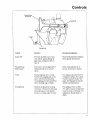
Controls
Rip Scale &
Indicator
Rip Lock
Yoke Lock
Handle
Saw
Handle
Bevel Lock Lever
(ontrol
Function
Operatio=_iComments
Yoke [rock Handle
Locks yoke in rip or crosscut
position
Pull handle forward to release;
push handle reward to tighten
Yoke index lever must be unindexed b@)re rotating yoke
Rip I.ock
locks carriage to radial arm for
ripping
Rotate counterclockwise
to
release carriage; turn clockwise
to Lock carriage in position
Lock before rq)ping
Rip Scale & Rip
Indicators
Tells approximate distance
between blade and fence when
saw" is in in-rip or out-rip position
Move blade carriage akmg arm
to align line on indicator with
desired number on scale
Saw I tandle
Provides grasping surface so
carriage can be moved.
Contains trigger mechanism to
raise clear plastic guard when
making a crosscut
Grasp to move blade carriage
Squeeze tr_,qer to fidly raise
cIear plastic guard. Clear
guard must be raised over fence
to crosscut
39
Controls
Guard
Clamp
Screw
Guard
Pawls/Riving
Knife Knob
Bracket
Riving
j
Knife
tn
Pawls
Hold Down
Control
Guard
Screw
Clamp
Guard
Function
Operation/Comments
Secures guard to motor; frees
guard for removal
Turn counterclockwise
to
loosen, clockwise to tighten
Protects against contact with
upper blade; partially protects
against contact with lower
blade; acts as sawdust deflector
Upper
part remains
fixed
in
level position. Notch in guard
fits securel), into matching
tab
on
motor
Clear guard is moveable: fully
raise over fence to crosscut; See
Saw Handle; most workpieces
will automatically raise clear
guard during ripping; See
Guard
Hold Down
Knob
Frees hold down to move up
and down; locks hold down in
place
Turn counterclockwise
Hold Down
During ripping, acts as partial
barrier to infeed side of Made;
keeps infeed side of workpiece
from fluttering; acts as sawdust
deflector
For ripping, lower hold down to
top of workpiece
surface, then
raise slightly and lock in place.
Prevents side to side movement
of riving kqifc and provides
means for adjusting alignment
[x)osen to align riving
then tighten
Riving Knife
Bracket
4O
Tab
loosen,
clockwise
For crosscutting
raised position
to
to tighten
lock in fully
knife,
Controls
Pawls/Riving
Knife Knob
Pawls
\
Riving Knife
Control
Guard
Tab
Function
Operation!Comments
Provides manual way to raise
clear plastic guard during rip-
Push and hold until workpiece
clears guard, then release
ping when
raise it
workpiece
fails to
Pawls/Riving
Knife Knob
Frees pawls
and riving
knife to
independently
down
move
Pawls
During ripping, slow or stop
kickback
by digging into workpiece; when lowered during
up and
crosscutting,
provide partial bartier to leading edge of blade
Riving Knife
Reduces
kickback
by keeping
kerr open; when lowered during
crosscutting,
provides partial
barrier to leading edge of blade
Turn _unterclockwise
to
loosen, clockwise to tighten
For ripping, set pawl level on
workpiece surface. For safety
reasons set pawls before ripping; See Ripping Set-Up for
details and illustrations
For ripping, lower to table
For safety reasons riving knife
must be in line with blade. See
Alignment: Riving Knife to
Blade
41
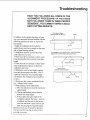
Electrical
Connections
Motor Specifications
,_
The AC motor used on this saw is a capacitor-start, non-reversible type. The models
covered in this manual have the following
specifications:
If not properly grounded, this power
tool could cause electrical shock,
particularly
when used in damp
locations.
Specification:
Model
Model
113.196221
Rated H.R
113.196321
Model
113.196421
1.5
1.5
1.5
2.5
2.75
3.0
Voltage
120
120/240
120/240
Amperes
l1
12/6
13/6.5
Hertz (cycles)
60
60
60
Phase
single
single
single
RPM
3450
3450
3450
clockwise
clockwise
clockwise
No
No
Yes
Max Developed
H.R
,arbor Shall Rotation
Run Capacitor
Note:
If saw does not start when
on, immediately
Troubleshooting.
destroy
WARNING
_IL WARNING
If electrical
shock
occurs,
your
reaction to shock could bring hands
into contact with blade.
_,WARNING
To avoid electric
shock
or fire,
immediately
replace worn, cut, or
damaged power cord.
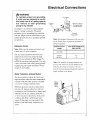
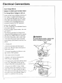
The unit is wired for 120V and has a plug
that looks like this:
3-Prong
Plug
switched
turn saw off and refer to
Leaving
the switch
on will
the motor.
Grounding
Prong
Properly
Grounded
Outlet
Power Supply
,_
WARNING
Saw is factory wired for 120V operation.
Connect
to 120V, 15-AMP
branch circuit and use 15-AMP time
delay fuse or circuit breaker.
Failure to connect in this way could
result in injury from shock or fire.
The saw must be properly grounded. Not all
outlets are properly grounded. If you are not
sure that your outlet is properly grounded,
have it checked by a qualified electrician.
42
The power tool is equipped with a 3-conductor cord and grounding type plug listed by
Underwriters'
Laboratories.
The ground
conductor has a green jacket and is attached
to the too! housing at one end and to the
ground prong in the attachment plug at the
other end.
The plug requires
a mating 3-conductor
grounded type outlet as shown above. If you
have an outlet that is of the 2-prong type, it
is recommended
that you have a qualified
electrician replace it with a properly grounded 3-prong outlet.
Electrical Connections
_,
WARNING
To maintain
proper tool grounding,
if outlet you are planning to use for
this power tool is a 2-prong type do
not remove
or alter grounding
prong in any manner.
An adapter
is available
plug to 2-prong
grounding
for connecting
receptacles.
manent ground
ed outlet box.
Lug
3-Prong
/
Plug
_'/
Make
to a per-
such as to a properly
ground-
Cords
The adapter
mum wire
#)) extension
3-wire
extension
the tool's
cord
Wire Gauge
with 3-prong
ground-
receptacles
which
Note:
Cord
2-
Wire Sizes Required for
120V (A.W.G.)
Motor Protection
& Reset Button
The motor
opens
14
12
The smaller
heavier
the circuit
the gauge
the cord. For circuits
numbe_
the
farther
away
['rom the electrical
circuit
must be increased
proportionately
ample
vo#age
box, wire size
to deliver
to the motor.
and
stops the motor when the motor temperature
exceeds a safe level, the motor is overloaded, or a low voltage
condition
exists.
When
activates,
immediately
the protector
grounded
No.
plug.
protector
is for use only
0-25 Ft
26-50 Ft.
the mini-
cord per table. Use only
cords
To A
!10-120V
cord will cause
Determine
ing type plug and 3-pole
accept
extension
illustrated
have a properly
Length
condition.
size (American
(AWG
Connected
receptacle.
Extension
sure the proper
loss of power.
This Is
Receptacle
Note:
The use of any extension
some
Sure
2-Prong
must be connected
is used and is in good
1_
lug extending
prong
Note:
Make
the
if you already
Extension
]
_=_
The green
lead or grounding
flom the adapter
Grounding
Manual
Re-Set
Button
(Red)
turn saw off, remove yellow key and wail
tot motor to cool. Push red re-set button and
listen/feel
re-sel.
for click to indicate
If you do not hear/feel
is still too hot. Wait a while
repeat.
motor
protector
a click,
longer
is
molor
and
(It may take over one hour for the
to cool sufficiently
for protector
to
reset.)
43
Electrical Connections
Dual Voltage
Motors
Models 113.196321 and 113.196421 ONLY!
To Change
Motor Voltage
to 240 A.C.
Under normal home workshop
conditions,
if
full voltage is supplied to the motor, your
saw will operate efficiently on 120V. If any
of the following conditions exist, it will be
advisable to have a qualified electrician
reconnect the motor for 240V operation:
• heavy duty operation
• either undersized
or overloaded
branch
circuit serves the saw
• power company cannot correct a low voltage situation.
The following procedure to change motor
voltage should be performed only by a qualified electrician. Note: Whenever cltanging
tlw ,n+'itch position from 120 to 240V,, make
certain that all necessary steps (including
proper fitsing of the branch circuit) are completed.
,_
DANGER
To avoid electric shock, unplug saw
before changing motor voltage.
Pan Head
Screw
1. Unplug saw.
2. Remove pan head screw from top of
motor cover. Remove motor cover panel at
blade end of motor.
3. Use small screwdriver
Molor Cover
Panel
to slide dual volt-
age switch to 240V position.
4. Re-insrall motor cover panel.
5. Replace 120V power cord plug with
240V, 15 amp, 3-prong plug.
Dual Voltage
Switch
6. Connect power cord white mad black leads
to two "hot" plug blades; connect power
cord grounding wire to plug ground prong.
7. Plug cord into 240V, 15 amp, 3-blade
receptacle.
Make
ed to a 240V
A.C. power
240V
circuit
branch
time delay
adapter
44
sure receptacle
having
fuse or circuit
is available
supply
is connectthrough
a
at least a 15 amp
breaker.
Note:
for this o_pe plug.
No
Crosscutting
Straight
Crosscutting
Bevel
Defined
Miter
Compound
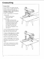
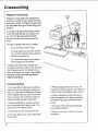
Crosscutting is cutting a workpiece to
length. The workpiece is held fh-mly against
the fence, and the blade is pulled through the
work_iece to make the cut. Straight, bevel,
miter, and compound cuts can be made.
Rolling Carriage
Crosscutting
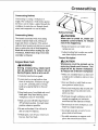
Safety
The hazards associated with crosscutting
include: exposed blade teeth, rolling carriage, and thrown workpiece. This section
explains these hazards and tells how to avoid
them or reduce the risk of their happening.
Read this section before making any type
of crosscut. Follow these steps every time
you make a crosscut.
WARNING
When saw is turned on, blade can
suddenly come forward. To reduce
risk of this happening:
",]Keep one hand on saw handle when
turning saw on.
x]Adjust leveling feet to make sure radial
ann slants slightly toward rear.
Thrown Workpiece
Exposed
Blade Teeth
WARNING
During crosscutting,
blade teeth
can be exposed. To reduce risk of
having fingers, hand or arm cut off:
_/Correctly
_/Lower
install and use guard.
pawls or riving knife to clear
fence or workpiece, whichever is higher, by 1/4". Lowered pawls or riving
knife act as partial barrier to front of
blade.
"4Keep hands away from blade and out of
blade path. Keep hand holding down
workpiece at least 8" from blade.
Blade can come off table edge beyond
30 ° left miter position. Use right miter
position whenever possible.
"4Do not cut freehand. You will not be
able to control workpiece.
_/If blade jams, turn off saw, remove yellow key, then free blade.
,_ CAUTION
Workpiece
could be picked up by
spinning
blade and thrown.
You
might be hit by thrown workpiece.
To reduce risk of thrown workpiece:
",]Make sure installed fence is at least half
as high as the workpiece,
than 3/4".
and never less
x/Start and finish cut with blade in rearmost position,
behind fence.
",/Firmly hold workpiece flat on table and
up against fence. Cut only one workpiece at a time.
_/Pull blade through workpiece only far
enough to complete cut, and never
more than half the diameter of blade.
Do not touch or move workpieces
until
blade has stopped spinning.
_/Use length stop only on end of workpiece which is held down.
_/Use table extensions to support workpieces that extend beyond table.
45
Crosscutting
Crosscut
Kerfs
A kerf or shallow
and fence
to serve
to ensure
through
cut is needed
in the table
as a path for the blade and
that the blade cuts all the way
the workpiece.
each different
To make
A kerf
cutting
is needed
for
path.
an approximately
1/16" deep kerf:
1. Prepare table:
- put fence in font position
- tighten table clamps
2. Prepare
blade:
- lock blade
in crosscut
position
- lock radial arm at desired
- lock motor
- unlock
at desired
miter
bevel
rip lock and push blade
rearmost
position,
- lower blade*
- lower
pawls
behind
angle
angle*
to
fcnce
to just clear table
or riving
knife to clear
fence by 1/4".
* raise
bevel
clearp&stic
angle
blade,
otherwise
3. Grasp
guard
changing
beveled
it may jam into table.
saw handle,
one hand
b(fore
and when lowering
then turn saw on. Keep
on saw handle
through
step
6.
4. Slowly lower blade until it touches table,
then lower one more full turn of crank.
5. Squeeze
plastic
handle
guard
through
trigger
to fully raise clear
so it will clear fence.
Pull blade
fence
and across
table as l_tr as it
6. Push blade
to rearmost
position,
will go.
fence,
handle
46
and turn saw off. Keep
behind
hand on saw
until blade stops spinning.
/
Crosscutting
Making Crosscuts
Follow
these steps to make
1 Prepare
crosscuts.
table:
- put fence in front position
- tighten
2. Prepare
table clamps
blade:
- lock blade in crosscut
posilion
- lock radial arm at desired
- lock motor
- unlock
at desired
miter
bevel
angle
angle*
rip lock and push blade
to
rearmost position, behind fence
- lower blade into keff* but not touching kerf bottom
(blade
should
move
freely).
* raise clear plastic
bevel angle
3 Position
or riving
workpiece,
whichever
saw handle,
against
plastic
handle
guard
workpiece.
fence,
is higher,
down
by 1/4".
through
step 7.
and against
trigger
to fully raise clear
through
only far enough to complete
more than half the diameter
fence.
from blade.
so it will clear
Pull blade
and
then turn saw on. Keep
Keep hand at least 8" away
6. Squeeze
beveled
knife to clear fence or
on saw handle
5. Hold workpiece
changing
it may jam into table.
workpiece
lower pawls
one hand
before
and when lowering
blade, otherwise
4. Grasp
guard
fence and
workpiece
but
cut, and never
of blade.
7. Push blade carriage to rearmost position,
behind fence, and turn saw off. Keep hand
on saw handle until blade stops spinning.
47
Crosscutting
Repetitive
Crosscutting
Repetitive crosscutting is the repeated and
continuous cutting of many pieces of lumber
to the same length. Carriage and length stops
can help make this type of crosscutting more
efficient.
Carriage
Stop
A carriage stop def'mes the distance needed
to pull the blade through to complete each
cut. This will prevent pulling the blade
through more than the recommended distance.
To make a carriage stop use Ix2 lumber:
i) cut two pieces, each 2" long
ii) clamp a piece on each side of radial
ann, so blade carriage stops at distance
needed to complete cut
iii) check that clamps do not interfere
with hand grip on saw handle.
A length
ensures
stop defines
the cut length
that all pieces
size. Clamp
a piece
fence to define
Crosscutting
will be cut to the same
of 1x2 lumber
the cut length.
stop only on the end
which is held down.
and
on the
Use a length
of the workpleee
Hints
1. To extend life of table top, buy auxiliary
table cover (see Accessories) or make one
out of 1/4" plywood or fiberboard. Clamp or
nail to original table top, section by ,section.
If you use nails, nail in the four comers to
make sure blade will not contact nails.
2. Make several fences, so each will have
only a few kerfs (See Cutting Aides). Too
many kerfs will weaken a fence.
3. Keep table clean of chips and sawdust.
4. Use sharp blades, and use the right blade
for each job.
48
5. When making miter or bevel cuts, use
extra force to hold workpiece down because
it tends to move during these types of cuts.
6. When cutting hard woods, like oak, or
making compound cuts, keep arm holding
saw handle rigid and pull blade through
slowly.
7. To keep cut line accurate, periodically
check blade alignment.
8. Do not cut severely warped or crooked
workpieces.
Ripping
Ripping Defined
Ripping is changing the width of a workpiece by cutting along its length. The workpiece is fed into the blade, which rotates in a
fixed position, parallel to the fence and a set
distance from the fence. A solid fence (no
kerfs) serves as a guide for the workpiece.
Place the fence in the front position for narrower workpieces, or in the rear position for
wider ones.
Front Fence
Position
L0
In-Rip and Out-Rip
o
- OR-
Rear Fence
Position
o
0_
Positions
hi-rip and out-tip refer to blade position.
In-rip: the blade is toward the column, and
the motor is toward the table front. In-tip is
recommended because this position allows
better visibility of the workpiece and your
hands. Use in-rip when you set the blade 1/2
to 16" from the fence.
Out-rip: the blade is toward the table front,
and the motor is toward the column. Use
Outleed
Side
out-tip only when you set the blade 12" or
more from the fence.
Infeed and Outfeed
Directions
lnfeed and outfeed refer to sides of the
blade.
In-Rip Position
Infeed: the side of the blade where the guard
hold down is. Always start a rip cut at the
infeed side and push the workpiece
through to the ouffeed side.
Outfeed:
the side of the blade where the
pawls and riving knife are. Never start a rip
cut at the ouffeed side. This is wrong way
feed. Never put hands on the ouffeed side
of the blade when ripping because they
can be pulled back into the spinning
blade.
Outfeed
Side
Pawls/Riving
Knife
Out-Rip Position
49
Ripping
Workpiece
Positioning
Always set up so that the wider part of
the workpiece is between the blade and
fence. This gives you greater clearance for
push sticks, and allows better stability for
feeding the workpiece.
Example: To rip 2" off a 10" wide board, set
blade in in-rip position 8" from rear fence.
Push Sticks and Push Blocks
Use push
the hands
complete
from the
auxiliary
sticks and push blocks instead of
to push the work_iece through to
cuts. They help keep hands away
blade, A push block is used with an
fence. (see Cutting Aides).
Use a push block and auxiliary fence
when the blade is set 1/2 to 2" from the
fence.
Use a push stick when the blade is set 2" or
more from the fence.
Do not set the blade closer than 1/2" to
the fence. The radial saw is the wrong tool
for such a narrow cut. A band saw would
be more appropriate for this type of cut.
Ripping _.P._fety
The hazards
outfeed
associated
zone hazard,
with ripping
kickback,
way feed. This section
explains
ards and tells how to avoid
include:
and wrong
these haz-
them or reduce
the risk of their happening.
this section
before
of rip cut. Follow
Read
these
you make
5O
a rip cut.
making
steps
any type
every
time
Ripping
Outfeed Zone Hazard
-_DANGER
a DANGER
Rotational
force of blade can pull
hands and fingers back into blade.
Touching,
holding,
or pulling on
outfeed side of workpiece
while
blade is still spinning will result in
fingers, hand or arm being cut off.
To reduce risk of outfeed hazard:
Set pawls and riving knife; they act as
partial barrier to outfeed side.
4 Start and finish cut from infeed side.
"4Keep both hands on infeed side.
Keep hands away from outfeed side.
Push workpiece through to complete
cut. Do not reach around to pull it.
"4If blade jams, turn saw off, remove yellow key, then free blade.
Kickback
Kickback
is the uncontrolled
the workpiece
,_
back
propelling
toward
of
the user.
,
WARNING
Kickback
pinched
Pinching
when:
--WARNING
can happen when blade is
or bound by workpiece.
or binding can happen
KICKBACK
• pawls
and riving
knife
are not used
or
not set correctly
• riving
• blade
knife is not aligned
is not parallel
with blade
to fence
• workpiece
is twisted
rocks on table top
or warped
and
• pressure is put on ouffeed side of workpiece
• workpiece
is released
pushed past pawls
• user
touches
through
outfeed
stopped
spinning.
or tries
side
before
being
to pull workpiece
before
blade
has
51
Ripping
To reduce risk of kickback:
_/Set pawls and riving knife according to
ripping set-up procedure. Correctly set
riving knife is more likely to prevent
workpiece from binding or pinching
blade; correctly set pawls are more
likely to grab into workpiece to stop or
slow kickback if one happens.
_/Check that riving knife is in line with
blade (see Alignment: Riving Knife to
Blade).
_/Cut only straight workpieces so surface
will lie flat on table and edge will stay
tight against fence. If you must cut an
irregular workpiece, attach a straight
edge (see Cutting Aides).
Wrong
Way Feed
Wrong way feed is ripping by feeding the
workpiece into the ouffeed side of the blade.
_/Push workpiece through from infeed to
ouffeed side until it is completely past
pawls.
",/Use featherboard
(see Cutting Aides).
_/Keep hands away from outfeed side.
_/If blade jams, turn saw off, remove yellow key, then free blade.
When cutting composition materials, or
other materials with one smooth and
one rough side, put rough side up so
pawls will be more likely to grab.
WARNING
_kWARNING
Rotational
force of blade will pull
workpiece through violently if workpiece is fed in same direction as
blade rotates
(wrong way feed).
Hands and fingers could be pulled
along with workpiece into spinning
blade before you can let go or pull
back. Fingers, hand or arm could be
cut off. Propelled workpiece
could
hit bystander.
To eliminate risk of wrong way feed:
_/Feed workpiece
against blade rotation.
_/Set pawls and riving knife; they act as
partial barrier to ouffeed side.
52
Wrong Way Feed
Ripping
Hold Down Function
The hold down
tipping
must be set correctly
to act as barrier
against
side of the blade,
to help keep
flat on the table,
and to deflect
chips.
It must be lowered
during
the infeed
the workpiece
workpiece
to just clear the
Set Hold-Down to
workpiece.
The hold down must be re-set each time a
different thickness
workpiece
just clear
__ ___
workqgiece is cut.
Follow the Ripping Set-Up Procedure
correctly set the hold down.
to
Pawls and Riving Knife Function
The pawls and riving knife must be set correctly during tipping to reduce the risk of
kickback, to prevent wrong way feed, and to
act as a barrier to the hazardous outfeed side
of the blade.
Set Pawl level
The riving
knife
the workpiece
chances
rests on the table.
It keeps
kerf open. This reduces
that the cut workpiece
rest level on the upper
the workpiece.
workpiece
the outfeed
motion
During
cutting
to pass freely
from
__J_
the
will spring
closed and pinch the blade. Pinching
blade is a cause of kickback.
The pawls
on workpiece
the
surface
of
they "allow the
the infeed
Set Riving Knife
fully down
to
side, but help stop the kickback
from ouffeed
bing into the workpiece
to infeed
side by grab-
surface.
The pawls must be re-set each time a different thickness workpiece is cut.
Follow the Ripping Set-Up Procedure to
correctly set the pawls and riving knife.
53
Ripping
WARNING
Ripping Set-up Procedure
Follow these stepsbefore ripping.
These steps must be repeated each time a
different thickness workpiece is ripped. A
kerf must be made for each different
If workpiece is pushed along fence
with kerfs, workpiece
could get
caught on kerf, pinch blade and
cause kickback. Do not use crosscutting fence for ripping.
width cut. Also see the special notes for
bevel set-up that follow this section.
1. Prepare table:
- insert solid (no kerfs) fence (Note:
Use auxiliary fence when blade is set
1/2 to 2"from fence (See Cutting
Aides)
- tighten table clamps.
2. Prepare blade:
- lock radial
- lock blade
- lower
blade
arm at 0 ° miter
in in-rip
position*
to just clear table
- lock blade carriage desired distance
from fence. Note: Make sure wider
part of worlqoiece
blade
will be between
and fence.
* use out-rip
position
for rips 12" or wider.
In-Rip Set-Up
3. Make kerf:
a) turn saw on
b) lower blade about 1/16" into table
c) turn saw off and remove yellow
key.
4. Place workpiece parallel to and up against
blade.** Note: Workp&ce will be between
blade and table front.
5. Lower hold down** to workpiece, then
raise slightly so it just clears top surface of
workpiece. Lock in place.
6. Lower riving knife to table. Lower pawls
to workpiece surface.** Move workpiece
toward outfeed side until one set of pawls
rests level on workpiece surface. Lock in
place.
** bevel
54
set-up:
see special
notes, next page
Setting Guard For Rip Cut
Ripping
8. Remove workpiece
from table.
9. Ready push stick or push block.
10. Set up table extension(s) and support
their outer ends. Do not use another person
to support workpieces because this can
cause kickback and it exposes helper to
potential hazards at outfeed side.
Special Notes for Bevel Set-Up
_CAUTION
Bevel ripping creates unique problems of visibility
and feeding.
Before cutting,
check the set-up
using both in-rip and out-rip. Use
the position
that gives the best
combination
of workpiece visibility
and push stick clearance.
,_WARNING
Bevel the edge that is not against
the fence.
1. When setting bevel angle, raise radial arm
to allow sufficient clearance for blade and
guard to not jam in table.
2. When blade is beveled manually raise
clear plastic guard before lowering blade to
table or kerf, otherwise it may jam in the
table.
3. To set hold down, place workpiece directly under guard nose, rather than parallel to
blade.
4. To set pawls, place workpiece directly
under set of pawls closer to table. This set of
pawls will keep contact with workpiece surface.
Making Rip Cuts
Follow these steps to make in-rip cuts. For
out-rip cuts, reverse hand functions; that is,
put right hand on table and use left hand to
support and push workpiece.
In-ripping
1. Follow ripping set-up procedure.
55
Ripping
2. Insert yellow key and turn saw on.
3. Stand at infeed side and out of line of
workpiece, in case of kickback.
finish cut from infeed side.
Start
and
4. Put workpiece on table, in front of hold
down, and tight against fence. To hold workpiece in position, put left hand on table, at
least 8" in front of hold down, and lightly
press fingers against workpiece. Support
workpiece with table extension or right
hand.
,_CAUTION
For large
workpieces
use a feather-
board
in place
of your
table.
It gives
better
cutting
hand
on the
support.
(See
aides)
Keep Hand
5. With fight hand, push workpiece
under
hold down and into blade. Keep left hand
fixed
on table,
applying
keep
workpiece
against
slight pressure
fence.
to apply feed
pressure
close to fence.
Note:
raise
infeed
to part of workpiece
hand
at least 8" in front of hold down.
Most
worbpieces
clear plastic
will automatically
guard
to ouOreed side.
narrow
guard.
Out-ripping
to
6. Use right hand to continue
Keep
Back
workpieces
When
as they pass from
Unusually
may not raise clear
this happens,
to raise guard,
tall and
then release
rests on top of workpiece
push guard
tab
tab when
guard
surface.
_IL CAUTION
Pushing guard tab means using
only one hand to control workpiece.
While pushing tab, use extra care to
guide workpiece
and to keep hand
at least 8" in front of hold down.
Release
rests
7. When
tab
as soon
as clear
Keep Hand
Back 8"
on workpiece.
end of workpiece
push stick or block,
of workpiece
between
push until workpiece
instead
gets to table, use
of hand,
on part
blade and fence
is completely
to
past
pawls.
8. Turn saw off and wait for blade
spinning
56
before
Tab
guard
touching
to stop
workpieee.
In-ripping
8"
Ripping
Dado Blades, Molding Heads
See Accessories for information on safety,
installation and use of dado blades and
molding heads.
Edging
Edging is the use of a dado blade or molding
head in the horizontal position. It is an
advanced technique that requires a molding
head guard and a sr,ecial fence. See
Accessories for information on safety, installation and use of dado blades and molding
heads for edging. See Cutting Aides for
information on making the special fence.
Ripping Hints
1. To extend
life of table
iary table cover
top, buy an auxil-
(see Accessories),
or make
one out of 1/4" plywood
or fiberboard.
Clamp
table top, section
or nail to original
by section. If you use nails, nail in the four
comers to make sure blade will not contact
nails.
2. Keep table clean of chips and sawdust.
3. Use shmp blades.
4. Use the right blade for each job.
5. For workpiece
rough
surface,
fiberboard,
with one smooth
such as paneling
cut with rough
pawls will be more
kickback.
6. _ib keep
check
blade
likely
cut line accurate,
and one
or finished
surface
up so
to grab in case of
periodically
alignment.
7. If you must cut an irregular workpiece,
attach a sn-aight edge (see Cutting Aides).
57
Cutting Aides
Before cutting any wood on your saw, study
all of the Crosscutting
and Ripping
Instructions
found on pages 41 through 53.
As you learn new radial arm saw woodworking techniques,
you'll see that many
types of cuts need different support and
feeding devices, known as jigs or fixtures.
They can help you make cuts more accurately. By helping to steady the workpiece
and
keep you away from the blade, they can help
you safely use your saw for certain cuts.
Many people custom build their own jigs
and fixtures. Jigs and fixtures are often
designed for a particular
cut.
You can use your radial saw to easily make
many jigs and fixtures. To get you started,
we've included instructions
for some simple
ones. After you have made a few practice
cuts, make up these jigs before starting any
projects. Make the push stick first.
Push Sticks
Push Stick
€
90 ° NOTCH
1/2" _
-.,,I
I]2"
Material For Push Block
_'_
At Least 12"
7
At Least
5-5/8"
3/8" THICK PLYWOOD
BASE
At Least
12"
_!
_--
1
3/4" THICK PLYWOOD
HANDLE
Make the push stick using a piece of 1 x 2.
(see drawing top right tor dimensions
and
shapes)
Push Block
There are any number of ways to properly
cut your v, ork pieces to make a push block.
The following
steps describe one way you
can proceed.
SLIGHTLY LESS THAN
THICKNESS OF WORKPIECE
UP TO 3/8" -X
3/4"
At Least
5"
V
Cutting out the Base
_
2-1/2"
-4"Th Cut
].
(save)
1 st Cut
Making the base:
• Start with a piece of 3/8" plywood
at least
5-5/8" wide or wider and 12" long or
longer.
• Make two ripcuts. Perform the first ripcut
along the long side of the 3/8" plywood
to
create a 3/8" wide strip. Next ripcut the
3/8" plywood
to a width of 5-1/8".
• Crosscut
the 3/8" plywood
to 12" long.
• Crosscut
a 2-1/2" piece offof the 3/8"
wide by 3/8" thick strip and save this short
piece for later.
• The next cuts will create the 3/8" by 91/2" notch in the base. Mark the long edge
of the board 2-1/2'" from one end. Make a
crosscut into the edge, stopping about 3/4"
into the board. Set the saw to the in-rip
position and rip the width lo 4-3/4" along
the same edge as the stopped crosscut.
Stop the ripcut where the two cuts intersect. Turn off the saw and remove the base
piece. The base
shown.
58
should
[lOW measure
as
2 nd Cut
12"
Creating the Notch
1 st Cut
i
2 nd Cut
4-3/4"
-_----_-Ji---
2-112"
Finished Base
=1
12"
_THESE
5"i]8"
+,+,+
4-3/4"
I
EDGES
MUST BE
PARALLEL
Cutti
Making the handle:
• Miter crosscut a piece of 3/4" fllick plywood to the shape and size shown. The
mitered comers can be any size that looks
like the drawing (about 1-1/2" by 1-1/2").
Cutting out the handle
1-112"V Jl
_
Putting it together:
• Using good quality wood working glue,
glue the 2-1/2" strip saved earlier to the
base as shown. Important:
Do not use
nails or screws. This is to prevent dulling
of the saw blade in the event you cut in to
the push block.
• Position the handle at the edge of the plywood base as shown. Fasten them together with glue and wood screws.
Important:
Make sure the screw heads
do not stick out from the bottom of the
base. The bottom must be flat and smooth
enough to slide along the auxiliary
you are now ready to make.
Auxiliary
Aides
5"
1-1/2"
12"
Assembly
only joint
fence
Fence:
Making the base:
• Start with a piece of 3/8" thick plywood
at
least 5-1/2" ',vide and at least 30" long.
• Cut the piece to 5-1/2" wide and 30" long.
Making the side pieces:
• Using 3/4" plywood
at least 30" long, ripcut one piece 2-1/4" wide and one piece
3-1/4" wide.
• Separately,
crosscut both pieces to 30"
long.
Putting R together:
• Glue and then fasten
with screws
I
I
Screwhead
must
be
AI
[
flush or recessed
the side
pieces to the base as shown. Make sure
the edge of the base and the face of the
side piece are parallel as indicated in the
note next to the drawing. Important:
Make
sure the screw or nail heads do not stick
out from the bottom of the base. The bottom must be flat and smooth
rest on the saw table without
enough to
rocking.
Auxiliary Fence
-3/4"
Glue
I
-_
2-1/4"
\
\
\
\
'X
Use 2 screws in at least 2 equally
spaced
locations
_long fence
(for a total ot 4 screws)
PLYWOOD
L
4-3/4"
3/8"
THIS FACE AND
THIS EDGE MUST
BE PARALLEL
59
Cutting Aides
Clamp the featherboard to the front table, so
that the angled edge of the featherboard is
against the workpiece on the infeed side of
the blade. Do not clamp the featherboard
against the cut off part (out-feed side) of
the workpiece. If clamped to the outfeed
side, the featherboard can squeeze the
kerf closed, put binding pressure on the
blade, and cause kickback.
Straight
Edge for Irregular Workpiece
_WARNING
If you try to rip an irregular workpiece, it could bind blade and cause
kickback.
ff the workpiece you want to rip does not
have a straight edge, attach a straight-edged
board to the workpiece:
a) place irregular side of workpiece
against fence
b) put straight-edged board on top of
workpiece and against fence
c) tack straight edged board to work
piece.
Note:
beyond
should
Straight-edged
leading
cover
board
must not extend
end of workpiece
workpiece
to pass between
blade
and
width only enough
and fence.
Note: Use fence at least as high as combined heights of workpiece and straightedged board.
6O
Accessories
Accessories
Safety
Information
1. Use only accessories listed in this section.
Use of any other accessory or attachment
might increase the risk of injury to you or
others.
2. Read and follow instructions
for Dado
1. Put inside loose collar on arbor shaft first,
then install dado. Tighten blade nut directly
against outside surface of dado.
2. Saw arbor
13/16" wide.
that come
is designed for dado up to
Use of wider dado could cause
with accessory.
dado
3. Do not install accessories
arbor shaft at same time.
er than 13/16"
with dado.
on both enck_ of
4. Do not use twist drill bits longer than 7"
because they can bend and break.
and blade nut to spin off. To make
3. To avoid
making
wide cut, take several
excessive
a 13/16"
load on motor
wide cut, limit depth
larg-
passes
when
of cut
to 1/8" in one pass.
5. Use a spade type drill 1" or smaller in
diameter for drilling only wood or plastic.
Information
Edging is the use of a dado or molding head
in the horizontal position. Edging requires
the use of a molding head guard (see
Accessories List)
6. Do not use reduced shank drills.
7. Remove blade wrenches before turning
saw
on.
,_DANGER
Grinding wheels, abrasive or cut off
wheels, or wire wheels can break
explosively
and throw pieces. You
can be blinded
or receive
a life
threatening
puncture
wound.
not use grind wheels, abrasive
cut off wheels, or wire wheels.
Do
or
_, WARNING
When
using
accessory
shaft,
exposed
arbor shaft can pull in
clothing,
hair or jewelry
as it
rotates. Broken bones and severe
cuts could occur.
Follow personal safety instructions.
Locate arbor shaft under radial arm:
lock blade carriage in out-rip
tion, then bevel motor to -90 °.
for Edging
posi-
1. Use molding head guard for edging with
molding head mad dado blade. Follow
instructions that come with guard. Do not
edge with a blade.
,_DANGER
Edging without a guard can bring
hands and fingers
too close to
blade. Hands, fingers and arm could
be cut off. Buy, install, and follow
instructions
for molding
head
guard.
,_WARNING
Blade cannot
be guarded
in horizontal position.
Edge with guarded
molding head or dado. Do not edge
with blade.
2. Whenever possible, edge with arm locked
at indexed 0° miter, so blade carriage is
more likely to lock firmly.
3. Before edging, with saw unplugged mad
yellow key out, turn cutting tool by hand to
make sure it does not strike guard or any
other part of saw.
61
Accessories
Accessories
These
saw.
for this Saw
accessories
Read
and
are designed
follow
to fit this
instructions
that
come
with accessory.
Item .............................................................
Auxiliary
Catalog
Table Cover ...................................
Blades (t0" with 5/8" hole) ...........................
No.
see catalog
see catalog
Dado Blades
Adjustable
Dado
7"-24 toolh carbide ...................................
see catalog
7"-32 tooth carbide ...................................
see catalog
7"-16 t(×_th carbide ...................................
see catalog
8"-48 tooth carbide ...................................
see catalog
Satin Cut [)ado
7". ..............................................................
see catalog
8". .............................................................
see catalog
8" carbide ..................................................
see catalog
Standard
Cut Dado
8". ..............................................................
see catalog
Drill Chuck & Key ........................................
see catalog
Dust Collector
Extenskm
....................................................
Table .............................................
Leg Set Caster .................................
Molding
9-29963
see catalog
9-22221 or 9-22222
Heads
7" bits not included
..................................
see catalog
7"-27 piece set ..........................................
see catalog
7"-15 piece set ..........................................
see catalog
Sanding Wheel - 10", .....................................
see catalog
Sanding Drum ....................................................
Taper Jig ........................................................
9-25246
see catalog
Guards
Molding
Head Guard -8". ........................
Accessor_
(supplied
L*)wer Guard ...............................
see catalog
9-290t0
with saw)
Books
Power To_l Know ttow tlandbook
62
............. 9-29114
Maintenance
General
Information
When new, the saw requires no hthrication.
Tile saw has been partially aligned and all
bearings are lubricated and sealed for life. In
time, in order to keep file saw in good working order, it will be necessary to clean, lubricate and re-align.
Oil Here
/,
1
,_WARNING
To avoid shock, burns, or lacerations from accidental
start up of
saw, turn power
switch
off and
unplug saw before doing maintenance or servicing saw.
Cam
Surface
Bevel Index Pin
Cleaning
Periodically remove any heavy build-up of
sawdust that may accumulate on the saw.
The absorbing tendency of sawdust will
draw lubricants away from the areas where
they are needed. Wipe the carriage bearings
and _'ack surfaces with a dry or lightly oiled
cloth.
Oil Here
Cam
To avoid motor damage due to sawdust
build-up, which interferes with normal
motor ventilation, vacuum the motor often.
Surface
Swivel Index Pin
Lubrication
Do not lubricate motor bearings, carriage
bearings, or the area between the miter lock
and the column tube. Motor and carriage
bearings are sealed and do not need added
lubrication.
Apply a few drops of oil to top of pin and
allow to flow down sides of pin. Move pm
up and down in its housing to work the oil
over sides of pin.
Areas that should be lubricated periodically
are the bevel index pin, swivel index pin,
and column tube.
You can lubricate other points if necessary,,
but only when sticking or binding occurs.
Use a small amount of SAE No. 10W30
automotive engine oil. Excess oil attracts airborn dust and sawdust.
63
Maintenance
Replacing
Pawls
Make sure the teeth of the pawls are "always
sharp. If they become dull the pawls must be
replaced:
1. Use 7/16" wrench to remove hex nut.
Remove old pawls.
2. Install new pawls, Place spacers exactly
as shown.
3. Re-install
hex nut.
4. Check that pawls work freely.
Blade Changing
To change the saw blade:
1. Turn switch off, remove yellow key, and
unplug saw.
2. Remove guard.
3, Use both blade wrenches in scissor action
to loosen blade nut. Note: Arbor shaft has
left-hand threads. Turn nut clockwise to
loosen.
4. Remove nut, blade collar, and blade.
Install ne_ blade, making sure that arrow is
on outside and points clockwise.
5. Re-install
blade collar and nut. Note: Do
not overtighten nut because this can cause
blade collar to warp and blade to wobble
during cutting.
6. Re-install
guard.
Grease
Pull Link
Lubricating
Blade
If guard becomes
Guard
Assembly
here
_
Slider
difficult to raise:
Slot
1. Clean sawdust from the slot and slider.
2. Regrease with a small amount of light
grease applied to the slot and slider. Also
add a thin coat of grease between the
Trigger and the Pull Link.
Adjusting
the Trigger
If the Trigger becomes loose side-to-side,
adjust the setscrews at the top of the Yoke
Handle. Use a 1/8" hex wrench to tighten
setscrews tight. Then back off one setscrew
unti! the T:-igger moves freely.
64
Adjust setscrews
Troubleshooting
HAVE YOU FOLLOWED ALL STEPS OF THE
ALIGNMENT
PROCEDURE?
IF YOU HAVE
NOT FOLLOWED THEM IN THEIR PROPER
SEQUENCE, YOU CANNOT EXPECT ACCURATE CUTTING RESULTS.
This Edge ol Board
Against Fence For All Cuts
In addition to the proper alignment of your
saw, you must also become familiar with the
following practices in order to expect the
best results.
1. Edge of workpiece which is placed
against fence must be as straight as the long
side of your flaming square.
2. Workpiece must be as flat as the front
table board on your saw.
3. There must be no sawdust or other wood
Fence
/
Turn Workpiece Over End For End...Keep Same Edge
Against Fence When Making Successive Cuts.
chips between the fence and the front table
board.
4. There must be no sawdust or other wood
chips underneath workpiece or between
workpiece and fence.
5. Workpiece must be held tightly against
fence and down against the table...this is
especially important when making angle
cuts because the workpiece has a tendency
to move.
Pencil Line For
Gauging
Required Length
Scrap
L
I
3rd Cut
6, Always use the correct sawblade for the
job...Always
keep it sharp.
7. When making a four sided frame:
a. The two side pieces must be exactly the
same length.
b. The top and bottom pieces must be
exactly the same length.
c. Always place the same edge of the
workpiece against, the fence...turn the
workpiece end for end for the successive cuts and mark a pencil line on the
table for gauging the required length.
Deviation from any of the above practices
wi!l have an effect on the accuracy of the
cuts that you make.
65
Troubleshooting
Possible
Motor overheats or stalls
Overloaded power line
Reduce line load by removing
other lights, appliances
Feeding rote too fast
Slow down rate of feed
Improper motor cooling
Vacuum sawdust from motor to
allow normal air circulation
Saw blade "hasheel
Check alignment
Saw blade is dull
Sharpen blade
Motor Overloaded
Slow down rate of feed
Need 15 amp circuit
Call your electrician
Need 15 amp slow-blow fuse
Install correct fuses
Low voltage
Check voltage. Norm'_ loads can
lye,vffely handled at 10% above or
below nameplate voltage; heavy
loads need same voltage at motor
terminal as on nameplate
Incorrect gauge extension cord
Refer to table in Electxical
Connections
Overloaded power line
Reduce line load by removing
other lights, appliances
Undersize wires or circuit too long
Increase wire size or shorten
length of wiring
Protector circuit open
Push re-set button; listen and feel
for click
Low voltage
Check power line for correct voltage
Sawdust build-up
Vacuum motor
Bent or bound-up arbor shaft
Check that shaft turns freely by
hand; if it doesn't, contact Sears
Internal damage
Take ,sawto Sears for service
While motor is running, fuses
blow
Motor starts slowly or fails to
come to ful! lx_wer
Motor will not run
Fuses blow when motor is turned
on
66
Cause(s)
What to Do
Motor Problem
Troubleshooting
Cutting
Problem
Possible
Inaccurate cut
Cros.scuts not accurate
at indexed
miter positions
Cause(s)
What
to Do
L_x)se locks
Check miter, rip, bevel, and swivel
locks. See AdiusUnents secliou
Saw blade out of alignment
Ch c_:k alignment
Sawdust
fence
between workpiece
and
Keep front table clean
Fence not straight
Replace
Swivel lock loose or not locked
Adjust swivel lock for wear
Crosscut
fence
travel not .square with
Square blade crosscut
Carriage
assembly
Adjust carriage bearings, then
realign _w
loose on arm
lence
travel
Am_ not indexing properly
Adjust miter lock for wear
Looseness between column tube
and column support
Adjust column support
Depth of crosscut varies from one
side of workpiece to other
Table not parallel with radial ann
Adjust table supports
Saw cuts at slight bevel
Blade not square to table
Square blade to table for crosscutting and ripping
Table not parallel to radial arm
Adjust table supports
Bevel lock loose
Adjust bevel lock
Work table not flat
Adjust or replace table
Carriage bearings
Wolkpiece kerr rough with tooth
marks from blade
Blade tends to advance through
workpiece too fast during crosseutring
loose
Adjust carriage bearings, then
realign _w
Blade not square to fence
Square blade to fence
Using improper blade for desired
finish cut
Use proper srnooth_utting blade
Blade dull
Sharpen or replace blade
User pulls blade through workpiece too fast
Pull blade slowly and steadily
through workpiece
67
Troubleshooting
Cutting
Problem
Possible
Cause(s)
What to Do
Workpiece strikes riving knife during ripping
Riving knife nol in line with blade
Align riving knife to blade
Workpiece binds, smokes, and
motor slows or stops when ripping
Saw blade out of "alignment
Re-align
Warped workpiece
Do not cut ,severely warped pieces
Feed rate too fast
Slow feed rote
Carriage assembly kx_
Adjust carriage bearings, then
realign saw
Fence not straight
Replace lence
Dull or incorrect blade
Shaq_en or replace blade
Saw blade out of alignment
Re-align
May occur as normal result of
applying feed pressure
U_ featherboard on infexxtside
Saw Problem
Possible
What to Do
Radial arm moves when locked in
a non-indexed miter position
Miter not locked lirmly
Adjust miter lock for wear
Motor moves when bevel lock is
locked
Bevel not locked firmly
Adjust bevel lock for wear
Yoke moves when rip lock is
locked
Rip lock not locked fu-mly
Adjust rip lock for wear
Blade carriage does not travel
smoothly on arm
Dirty track
Clean and lubricate track
Carriage bearings set too tight
Adjust carriage bearings, then realign saw
Rip lock rubbing track
I_x×_senRip Lock
Worn steel track
Replace track
Bad carriage bearing
Replace carnage bearing
Blade nut loose
Tighten blade nut
Internal damage
Take saw back to Sears for service
Board pulls away from fence during ripping
Blade does not stop spinning within 15 seconds after saw is turned
off
68
Cause(s)
Notes
69
::0
"--4
O
PARTS LIST FOR CRAFTSMAN 10" RADIAL SAW
MODEL NUMBERS 113.196221; 113.196321 & 113.196421
f_
Ill
"13
13
23
RGURE1
14
15
24
16
25 26 27
e,,,,,i-
PARTS LIST FOR CRAFTSMAN 10" RADIAL SAW
MODEL NUMBERS 113.196221; 113.196321 & 113.196421
Always order by Part Number - Not by Key Number
FIGURE 1
Key
No
Part
No.
1
2
3
63518
75090
60339
4
5
6
7
60353
815649
63669
STD601105
8
9
10
11
12
63670
821361
63686
805494
436594
13
14
15
16
17
18
19
STD551010
63884
63885
STD541110
STD551131
9421620
20
21
821473-3
60337
22
23
24
STD512520
821367
Descriplion
Cord, with Plug
Cover, Rear Arm
Screw, Hex Hd Locking, 3/8-16
x 2-1/8 High Strength
Washer, .380 x 47/64 x 1t8
Bearing, Arm
Scale, Miter
* Screw, Pan Rec. Hd
10-32 x 3/8
Indicator, Miter
Trim Arm
Pad, Arm Trim
Nut, Square 3/8-16
* Screw, Pan Rec. Hd 10-32 x
1-1!2
* Washer, 13/64 x 7t16 x !/16
Knob, L.H. Lever Arm
Knob, R.H Lever Arm
* Nut, Hex 10/32
Arm Assembly, See Fig. 5
* Lockwasher, 5116
Screw, Soc. Hd Cap 5/16-18
x 1/2
Cap, Arm
Screw, Type 'T' Pan Hd
10/32 x 7/8
Yoke Assembly, See Fig. 2
* Screw, Pan Hd 1/4-20 x 1-3/4
Table, Rear
Key
No
Part
No.
25
26
27
28
29
30
31
32
33
34
35
36
37
38
39
40
41
42
43
44
821368
63432
821366
102711
STD551012
STD512510
37384
37530
STD551125
STD541025
818161
818166
120399
818162
STD541437
63467
60342
63881
9420417
45
46
47
48
-
63683
63682
3540
SP5667
Description
Table, Spacer
Fence, Rip
Table, Front
Screw, Set SL. Cup 1/4-20 x 1
* Washer, 17/64 x 5/8 x 1t32
* Screw, Pan Hd 1/4-20 x 1
Nul, Tee
Nut, "U" Clip
* Lockwasher, 1/4
Nut, Hex 1/4-20
Shoe, Table Clamp
Bracket, Clamp
Nut, Square 5/16 - 18
Screw, Clamp
Base Assembly, See Fig. 3
* Nut, Lock 3/8-16
Cap, Flag Terminal
Bolt, Sq. Hd 3/8-16 x 2-1/4
Clamp, Cord
Screw, Type 'q-" Hex Washer
Hd 1/4-20 x 5!8
Guard Assembly, See Fig. 4
Wrench, Hex "L" 3/16
Wrench, Hex "L" 1/4
Wrench
Owners Manual (Not Illustrated)
mill
"O
* Standard Hardware Item- May Be Purchased Locally.
PARTS LIST FOR CRAFTSMAN
10" RADIAL SAW
MODEL NUMBERS 113.196221; 113.196321 & 113.196421
m
ml
37
44
30
28 2
49
23
50
• Any attempt to repair this motor may create a HAZARD unless repair
is done by a qualified service technician. Repair service is available
at your nearest Emerson Retail Store.
FIGURE
2
PARTS
MODEL
Key
No
1
Part
No.
STD601105
2
3
4
5
6
7
8
9
10
11
12
13
14
63661
63786
STD510605
120399
63657
63893
63658
63656
STD55!031
STD551231
STD523107
63778
63782
15
!6
17
18
19
20
63777
STD541462
STD551062
30567
3053O
60336
21
22
23
24
25
26
27
28
29
30
31
32
33
34
63779
63528
30521
63659
63660
63641
STD541231
30495
62498
9-32668
STD541437
STD551037
63652
63651
LIST FOR CRAFTSMAN
10" RADIAL
NUMBERS
113.196221;
113.196321
FIGURE 2 - YOKE ASSEMBLY
Description
* Screw, Type "F' Pan Rec. Hd
10-32 x 1/2
Cover, L.H. Carriage
Indicator, Rip
* Screw, Pan Rec. Hd 6-32 x 1/2
Nut, Square 5/16-18
Housing, Index Pin
Pin Assembly, Index
Spring, Index
Bracket, Spring
* Washer, 21/64 x 3/4 x 1/16
* Lockwasher, 5/16, Ext. Tooth
* Screw, Hex Hd 5/16-18 x 3/4
Screw, Eccentric
Washer Assembly, Carriage
Bearing
Bearing, Carriage
* Nut, Lock 5/8-11
* Washer, .630 x 1.125 x .093
Bumper
Nut, Speed
Bolt, Hex Hd 5/16-18 x 1-1/2
High Strength
Bearing, Sleeve
Shoe, Rip Lock
Spring, Swivel Latch
Cover, R.H. Carriage
Knob, Carriage Lock
Carriage
* Nut Hex Jam 5/16-18
Nut, Shaft
Collar
1"Blade, Saw
* Nut, Lock 3/8-16
* Washer, .380 x 47/64 x 1/16
Cam, Motor
Stud, Motor
* Standard Hardware Item - May Be Purchased Locally.
1-Stock item - May be secured through the hardware
departments of most Sears Retail Stores.
SAW
& 113.196421
Key
No
Part
No.
35
36
37
38
39
40
41
42
43
44
63469
63642
63648
63643
63644
60333
63645
30582
63620
60337
45
STD600803
46
47
48
49
5O
51
52
63662
821354
821342
9421628
STD551131
60288
9421627
53
54
55
63650
63649
60335
56
57
58
63647
STD551210
806214
59
60
61
--
STD523120
63646
821506
821545
62
63
30613
STD600805
Description
Bushing,
Yoke
Rubber
Knob, Bevel Index
Stud, Yoke Clamp
Handle, Yoke Lock
Nut, Square L.H. 5/16-18
Pin, Index
Cap, Shaft
Trim, Yoke
* Screw, Type 'T' Pan Rec. Hd
10-32 x 7/8
* Screw, Type 'T' Pan Rec. Hd
8/32 x 5/16
Indicator, Bevel
Trigger
Handle, Yoke
Screw, Soc. Cap 5/16-18 x 2
* Lockwasher,
5/16
Screw, Set 1/4 - 20 x 3/8
Screw, Soc. Cap
5/16-18 x 1-5/8
Plate, Retainer
Ring, Index
Screw, Hex Hd L.H.
5/16-18 x 2
Lever, Bevel Lock
* Lockwasher,
Ext. Tooth No. 10
Screw, Hex Soc. Button Hd
Cap 10-32 x 5/8
* Screw, Hex Hd 5/16-18 x 2
Cap, Yoke
• Motor (Model 113.196421)
Motor (Models 113.196221,
113.196321)
Clamp, Cord
Screw, Pan
TY 'q-" 8-32 x 1/2
• Any attempt to repair this motor may create a HAZARD unless
repair is done by a qualified service technician. Repair service is
available at your nearest Sears Store.
"O
MIIIIm II
13
Q}
PARTS LIST FOR CRAFTSMAN 10" RADIAL SAW
MODEL NUMBERS 113.196221; 113.196321 & 113.196421
::D
(1)
mll
26
18
'!3
27
19
28
U)
27
29
\
28 46 45
44
43
FIGURE 3
PARTS
MODEL
LIST FOR CRAFTSMAN
NUMBERS
113.196221
10" RADIAL
; 113.196321
SAW
& 113.196421
Always order by Part Number - Not by Key Number
FIGURE - 3 BASE ASSEMBLY
Key
No
Part
No.
1
2
3
4
5
6
7
8
STD503705
63623
60330
63611
63610
STD572510
821346
9416187
9
10
11
12
13
14
15
16
17
STD523110
60078
STD541037
STD 551137
60340
STD523712
186648
817398-1
60367
18
60336
19
20
21
63609
821348
63500
22
63614
Description
* Screw, Soc. Set 3/8-16 x 1/2
Latch, Arm
Ring, Retaining 3"
Tube
Gib, Column Tube
* Pin, Roll 1/4x 1
Nut, Elevation
* Screw, Type "T" Hex Washer
Hd. 5/16-18 x 3/4
* Screw, Hex Hd. 5/16-18 x 1
* Screw, Hex Hd. 5/16-18 x 1/2
* Nut, Hex 3/8-16
* Lockwasher, 3/8
* Washer, .380 x 7/8 x 1/8
* Screw, Hex Hd 3/8-16 x 1-1/4
* Screw, Hex Hd. 5/16-18 x 1-7/8
Screw, Locking Capl/4-20 x 5/8
Bolt, Hex Hd. 5/16-18 x 1-7/8
High Strength
Bolt, Hex Hd. 5/16-18 x 1-1/2
High Strength
Support, LH.
Shaft, Elevating
Washer, Thrust .502 x .927
x .031
Bearing
Key
No
Part
No.
23
60300
24
25
26
27
28
29
30
31
32
33
34
35
36
37
38
39
40
41
42
43
44
45
46
47
818164
STD541450
63619
STD541031
STD541431
STD581037
818165
63617
STD551050
STD581050
821333
STD541025
STD551125
63622
63435
STD551012
STD522505
STD502503
63434
63621
818199
STD551031
STD551131
109163
Description
Washer, 1/2 x 7/8 x .010
(as required)
Gear, Bevel
* Nut, Lock 1/2-13
Support, R.H.
* Nut, Hex 5/16-18
* Nut, Lock 5/16-18
* Ring, Retaining 3/8
Gear, Pinion
Bearing, Elevating Shaft
* Washer, .515 x .875 x .032
* Ring, Retaining 1/2
Shaft, Elevating Crank
* Nut, 1/4-20
* Lockwasher 1/4
Bracket, Bearing
Bushing
* Washer, 17/64 x 9/16 x 3/64
* Screw, Hex Hd. 1/4-20 x 1/2
* Screw, Soc. Set 1/4-20 x 3/8
Crank, Elevating
Base
Channel, Table Mounting
* Washer, 11/32 x 7/8 x 1/16
* Lockwasher, 5/16
* Bolt, Square Hd 5/16-18 x 3/4
m|
"!3
* Standard Hardware Item - May Be Purchased Locally.
:O
PARTS LIST FOR CRAFTSMAN 10" RADIAL SAW
MODEL NUMBERS 113.196221; 113.196321 & 113.196421
"0
Always order by Part Number - Not by Key Number
2
3
4
imlml ii
1
5
37
7 6
;Z
8
10
9
11
17
12
13
27
29
15
28_
13
14
14
Location of Lower Guard
26
y
34-
25
Lower
GuardS,ot
.,___r
_!
_
Washer
Screw
SEE DETAIL "A"
Lower
FIGURE 4
DETAIL "A"
"0
nner Guard
PARTS LIST FOR CRAFTSMAN 10" RADIAL SAW
MODEL NUMBERS 113.196221; 113.196321 & 113.196421
Always order by Part Number - Not by Key Number
FIGURE 4 - GUARD
Key
No
Part
No.
1
2
3
4
821217
821313
STD551012
815865
STD601105
6
7
8
9
802392-47
808447-6
820529
STD551031
10
11
12
13
820521
820515
STD541425
STD551025
14
15
16
17
18
815815
820517
STD512510
820512
824159
Description
Screw, Guard Clamp
Link, Purl
* Washer, 17/64 x 5/8 x 1/16
Screw, He)( Washer Hd Type
"IT' 1/4 - 20 x 1/2
* Screw, Pan Hd Type
"-IT' 10-32 x 5
Spacer #10 x ,125
Washer, Spring
Knob, 5/16-18
* Washer
21/64 x 5/8 x 1/16
Spacer
Knife, Riving
* Nut, Lock 1/4-20
* Washer
17/64 x 5/8 x 1/16
Pawl, AKB
Bushing
* Screw, Pan Hd. 1/4-20 x 1
Holder, AKB
Screw, Flat Hd Type "TT"
1/4- 20 x 9/16
Key
No
Part
No.
21
22
23
24
25
26
820519
STD551225
820530
808822-1
820532
809019-4
27
28
805641-1
STD533107
29
30
31
32
33
34
35
36
37
38
39
820985
808380
805548-10
821312
821311
82131O
821314
60413
63258
821449
824158
Description
Nut, Slotted 1/4 - 20
* Lockwasher 1/4
Support, Knife
Nut, Push 1/4
Bolt
Bolt, Rd Hd Short Neck
5/16 - 18 x 1-3/4
Ring, Retaining
* Bolt, R.H. Short Neck
5/16 - 18 x 5/8
Lower, Inner Guard
Scr Plastite #8-16 x 1/2
Washer 3/16
Guard
Link
Guard, Lower
Hold Down
Nut, Push 5/16
Elbow, Dust
Nut, Square 5/16 - 18 Double
Strap-Retainer
Q}
* Standard Hardware Item - May Be Purchased Locally.
m|
"!3
Repair Parts
PARTS LIST FOR CRAFTSMAN 10" RADIAL SAW
MODEL NUMBERS 113.196221, 113.196321 & 113.196421
3
4
24
26
FIGURE
Key
No
1
2
3
4
5
6
7
8
9
10
11
12
13
14
15
Part
No.
63626
63629
63631
63628
9420417
63883
63632
63630
63633
60240
STD551031
63872
STD551012
60208
63638
5 - ARM
Description
Housing, Pin
Pin, Arm Index
Pawl, Arm Lock
Spring, Tension
Screw, Type "T" Hex Washer
Hd 1/4-20 x 5/8
Guide
Rod, Index
Spring, Arm Lock
Rod, Arm Lock
. Nut, Push 3/8
Washer, 21/64 x 1 x 1i8
Lever, Arm Lock
" Washer, 17/64 x 5/8 x 1/32
* Nut, Push 114
Pin, Lever
25
ASSEMBLY
Key
No
Part
No.
16
17
18
19
63637
63636
63773
STD601103
20
21
22
STD551210
63639
448337
23
24
9-22255
STD600805
25
63896
26
27
63878
60440
Description
Pin
Pin, Clevis
InsuLation
* Screw, Type "T" Pan Hd
10-32 x 3/8
* Lockwasher, Ext. Tooth N10
Track
Screw, Type 'q" Rd. Hd
10-32 x 5/8
1"Key
* Screw, Type 'q" Pan Hd
8-32 x 1/2
Switch, Locking
(Includes Key No. 23)
Arm, Radial
Clamp, Cord
* Standard Har_'_are Item may be Purchased Locally.
. It this part is removed, discard and replace with a new
Push Nut.
78
Repair Parts
PARTS LIST FOR CRAFTSMAN
10" RADIAL SAW
MODEL
NUMBERS
113.196221,
113.196321
& 113.196421
4
4
13
FIGURE
Key
No
1
2
3
4
5
6
7
Part
No.
821343
60314
821779
821780
STD551225
STD541025
STD523106
6-
LEG SET
i
Description
Key
No
Part
No.
Description
i
Leg
Screw, Truss Hd. 1/4-20 X 5/8
Stiffener, Side
Stiffener, Front/Rear
* Lockwasher, External 1/4
* Nut, Hex 1/4-20
* Screw, Hex Hd 5/16-18 x 5/8
8
9
10
11
12
13
STD551031
STD551131
STD541231
STD541037
803835-1
821360
* Washer, 11/32 x 11/16 x 1/16
* Lockwasher, External 5/18
* Nut, Hex Jam 5/16-18
* Nut, Hex 3/8-16
Foot, Leveling
Lower Stiffener
(113.196421 Only)
* Standard Hardware Item may be Purchased Locally.
79
f
f
10-1NCH RADIAL SAW
owner's
manual
SERVICE
For the repair or replacement parts you need
Call 7 am - 7 pm, 7 days a week
MODEL NO.
113.196221
113.196321
SAW WITH LEGS
or
113.196421
CONTRACTOR'S SAW
1-8OO-366-PART
(1-800-366-7278)
For in-home major brand repair service
Call 24 hours a day, 7 days a week
1-800-4-REPAIR
(1-800-473-7247)
The model number of your
lO-Inch Radial saw is found at
the front of the base.
When requesting service or
ordering parts, always provide
the following information:
• Product Type
• Model Number
• Part Number
• Part Descripbon
For the location of a
Sears Repair Service Center in your area
Call 24 hours a day, 7 days a week
1-800-488-1222
For information on purchasing a Sears
Maintenance Agreement or to inquire
about an existing Agreement
Call 9 am - 5 pm, Monday-Saturday
1-800-827-6655
SEARS
q;{:_ fl;l,']:;irJ[_]_'Jl
Arner,C_l
Sears
Part No. SP5667
Roebuck
S ,_paff
SL_ecla/!sts
and Co., Hoffman
Estates,
Form No, SP5667-5
IL 60179
U.S.A.
Printed
in U,S,A, 5/96