1
9800 Martel Road
Lenoir City, TN 37772
www.ps-engineering.com
PMA7000S
PMA7000M-S
with Options
Document P/N 200-070-0012
Revision 12, September 2000
Patent No. 5,903,277
FAA-Approved TSO C50c, C35d
JAA-Approved JTSO-2C35d, C50c
Audio Selector Panel
Marker Beacon Receiver
High-fidelity Stereo Intercom System
Installation and Operation Manual
In certified aircraft, warranty is not valid unless this product is installed by an
Authorized PS Engineering dealer.
PS Engineering, Inc. 2000 ©
Copyright Notice
Any reproduction or retransmittal of this publication, or any portion thereof, without the expressed written permission of PS Engineering, Inc. is strictly prohibited. For further information contact the Publications Manager at PS Engineering, Inc., 9800
Martel Road, Lenoir City, TN 37772. Phone (865) 988-9800, email [email protected].
Table of Contents
1 SECTION I GENERAL INFORMATION .........................................................................1-1
1.1
INTRODUCTION...........................................................................................................1-1
1.2
SCOPE .............................................................................................................................1-1
1.3
EQUIPMENT DESCRIPTION .....................................................................................1-1
1.4
APPROVAL BASIS - .....................................................................................................1-2
1.5
SPECIFICATIONS.........................................................................................................1-2
1.6
EQUIPMENT SUPPLIED .............................................................................................1-4
1.7
EQUIPMENT REQUIRED BUT NOT SUPPLIED....................................................1-4
1.8
LICENSE REQUIREMENTS .......................................................................................1-4
2 SECTION II - INSTALLATION .........................................................................................2-1
2.1
GENERAL INFORMATION ........................................................................................2-1
2.1.1
SCOPE........................................................................................................................2-1
2.1.2
CERTIFICATION REQUIREMENTS .................................................................................2-1
2.2
UNPACKING AND PRELIMINARY INSPECTION ................................................................2-1
2.3
EQUIPMENT INSTALLATION PROCEDURES ....................................................................2-1
2.3.1
COOLING REQUIREMENTS ...........................................................................................2-1
2.3.2
MOUNTING REQUIREMENTS .......................................................................................2-1
2.3.3
MOUNTING RACK INSTALLATION ...............................................................................2-2
2.3.4
CONNECTOR ASSEMBLY .............................................................................................2-2
2.4
CABLE HARNESS WIRING ...............................................................................................2-2
2.4.1
NOISE ..........................................................................................................................2-3
2.4.2
EXISTING KMA-24 INSTALLATION .............................................................................2-3
2.4.3
EXISTING PMA6000 INSTALLATIONS .........................................................................2-3
2.4.4
POWER ........................................................................................................................2-4
2.4.5
COMMUNICATIONS PUSH-TO-TALK ............................................................................2-4
2.4.6
AUDIO PANEL INTERFACE ...........................................................................................2-4
2.4.7
COM 3 AUDIO..............................................................................................................2-4
2.4.8
TRANSMIT INTERLOCK ................................................................................................2-4
2.4.9
"SWAP" MODE ............................................................................................................2-4
2.4.10
BACKLIGHTING..........................................................................................................2-5
2.4.11
UNSWITCHED INPUTS ................................................................................................2-5
2.4.12
PA MUTE (J1, PIN 18)...............................................................................................2-5
2.4.13
PUBLIC ADDRESS FUNCTION (J2, PIN 18) .................................................................2-5
2.4.14
CONTROL OUTPUT (J2, PIN A) ..................................................................................2-5
2.4.15
INTERCOM WIRING ....................................................................................................2-5
2.4.16
VOX OVERRIDE (J2, PIN U) .....................................................................................2-6
2.4.17
INTERCOM EXPANSION (J2, PINS P, S, AND C)..........................................................2-6
2.4.18
PLAYBACK BUTTON INSTALLATION (J2, PIN 19- OPTIONS 1, 2 AND 7 ONLY) ........2-6
2.4.19
AUDIO MESSAGE ACKNOWLEDGE (J2, PIN W) OPTION 1 AND 2 ONLY) ..................2-7
2.5
MARKER BEACON INSTALLATION ..................................................................................2-7
2.5.1
MARKER ANTENNA INSTALLATION ............................................................................2-7
2.5.2
EXTERNAL MARKER LIGHTS (7000MS) .....................................................................2-7
2.5.3
MIDDLE MARKER SENSE (700MS) .............................................................................2-7
2.5.4
MARKER AUDIO INPUT (7000S)..................................................................................2-7
2.6
ADJUSTMENTS ..................................................................................................................2-7
2.7
COMMUNICATIONS ANTENNA INSTALLATION NOTES ..................................................2-8
2.8
WIRELESS TELECOMMUNICATIONS INTERFACE ...........................................................2-8
2.8.1
HOOK SWITCHES .........................................................................................................2-9
PS Engineering
PMA7000M-S Series Audio Selector Panel and Intercom System
Installation and Operator’s Manual
PMA7000M-S PIN ASSIGNMENTS (STANDARD VERSION ONLY) ...........................................2-10
2.10
POST INSTALLATION CHECKOUT ...............................................................................2-11
2.11
UNIT INSTALLATION ....................................................................................................2-11
2.11.1
OPERATIONAL CHECKOUT ......................................................................................2-11
2.11.2
RECEIVER SENSITIVITY ...........................................................................................2-12
2.12
CELLULAR INTERFACE CHECKOUT............................................................................2-12
2.13
INTERNAL RECORDER CHECKOUT (OPTIONAL)........................................................2-12
2.14
DIGITAL ANNUNCIATION CHECKOUT (OPTIONAL) ...................................................2-12
2.15
FINAL INSPECTION .......................................................................................................2-12
3 SECTION III OPERATION ...............................................................................................3-1
3.1
SCOPE .............................................................................................................................3-1
3.2
POWER SWITCH (EMG-FAIL SAFE OPERATION) ..........................................................3-1
3.3
MICROPHONE SELECTOR (ALL MODELS) ......................................................................3-1
3.3.1
SWAP MODE (SWITCH FROM COM 1 TO COM 2 REMOTELY) ......................................3-2
3.4
AUDIO SELECTOR (ALL MODELS)...................................................................................3-2
3.4.1
SPEAKER AMPLIFIER ...................................................................................................3-2
3.4.2
KEY “CLICK” ..............................................................................................................3-3
3.5
SPLIT MODE .....................................................................................................................3-3
3.5.1
SPLIT MODE ICS .........................................................................................................3-3
3.6
INTERCOM OPERATION ...................................................................................................3-3
3.6.1
INTELLIVOX® VOX-SQUELCH ....................................................................................3-3
3.6.2
VOLUME CONTROL .....................................................................................................3-4
3.6.3
INTERCOM MODES ......................................................................................................3-4
3.7
TELEPHONE MODE ..........................................................................................................3-6
3.8
MARKER BEACON (PMA7000M-S)................................................................................3-6
3.9
INTERNAL RECORDER SYSTEM (OPTIONAL) .................................................................3-7
3.9.1
OPERATION .................................................................................................................3-7
3.10
AUDIO MESSAGING SYSTEM (OPTION 1, OPTION 2, ONLY) ........................................3-7
3.10.1
CONCURRENT MESSAGES .........................................................................................3-7
4 SECTION IV- WARRANTY AND SERVICE ...................................................................4-1
4.1
WARRANTY ......................................................................................................................4-1
4.2
FACTORY SERVICE ..........................................................................................................4-1
5 APPENDIX A EXTERNAL PTT HOOK UP ...................................................................... A
6 APPENDIX B – INSTALLATION DRAWING ................................................................... B
7 APPENDIX C BOTTOM CONNECTOR INTERCONNECT ........................................... C
8 APPENDIX D TOP CONNECTOR INTERCONNECT ..................................................... D
9 APPENDIX E- INSTRUCTIONS FOR FAA FORM 337 AND CONTINUING
AIRWORTHINESS ...................................................................................................................... E
9.1
INSTRUCTIONS FOR FAA FORM 337, AUDIO PANELS ..................................................... E
9.2
INSTRUCTIONS FOR CONTINUING AIRWORTHINESS, AUDIO PANELS ............................. E
10 APPENDIX F RTCA DO160C (EUROCAE ED-14) ENVIRONMENTAL
QUALIFICATION FORM .......................................................................................................... F
200-070-0012
Page ii
Rev. 12, Sept. 2000
PS Engineering
PMA7000M-S Series Audio Selector Panel and Intercom System
Installation and Operator’s Manual
Section I GENERAL INFORMATION
1.1
INTRODUCTION
The PMA7000M-S represents the next step in cockpit audio control and intercommunications. Using proprietary IntelliVox® design, this unit eliminates the requirements for intercom squelch adjustments. The unit
is designed for outstanding ergonomics and visually defined mode annunciation and selection.
Before installing and/or using this product, please read this manual completely. This will ensure that you
will take full advantage of all the advanced features in the PMA7000M-S.
1.2
SCOPE
This manual provides detailed installation and operation instructions for the PS Engineering PMA7000M-Sseries of Audio Selector Panel/Intercom Systems. This includes the following units:
Model
PMA7000S
PMA7000M-S
Option 1 added to any unit
Description
Part Number
Stereo Audio Selector Panel
7000S
Stereo Audio Panel with Marker
7000MS
Same as above, with optional recorder and mes- Opt.1
sage system
Option 2 added to any unit
Same as above, with optional recorder and mes- Opt 2
sage system for Vista Map Software
Option 3 added to any system
Black bezel (no silver trim)
Opt 3
Other options may be applied for exclusive use by specific aircraft manufacturers, under Type Certification Call for information.
Where the functions are identical to all units, it will be referred to herein as a PMA7000M-S. Otherwise, the
applicable units will be specified.
1.3
EQUIPMENT DESCRIPTION
The PMA7000M-S-series is a state of the art audio isolation amplifier and audio selector that contains an
automatic voice activated (VOX) intercom system. It can switch up to three transceivers (Com 1, Com 2
and Com 3) and six receivers (Nav 1, Nav 2, ADF, DME, MKR and AUX).
The TEL mode allows the PMA7000M-S to act as an audio interface between aircraft headphone and microphones and specific aircraft approved (FAA/FCC) cellular telephone equipment.
Warning: Use of non-aviation approved cellular telephone equipment may be prohibited by regulation.
PS Engineering is not responsible for unauthorized airborne use of cellular telephones.
For airborne use, the PMA7000MS must be interfaced with the AirCell AGT.01.
There are two unswitched inputs, for autopilot disconnect, and/or radar altimeter warning. Push buttons
select the receiver audio source provided to the headphones. A SPR button allows the user to listen to the
receiver(s) selected on the cabin speaker. Except for the unswitched inputs, all speaker audio is muted during transmit.
A rotary switch selects one of the three communication transceivers for the pilot and copilot position, and
allows radio transmission. In "Split Mode" the PMA7000M-S has the ability to allow the pilot and copilot
to operate different transceivers independently. The TEL mode allows the pilot to use the cellular telephone
interface. External switches permit telephone operation for the copilot and passengers.
A fail-safe mode connects the pilot headphone and microphone to COM 1 if power is removed for any reason, or if the power switch is placed in the Off (Fail-safe) position.
200-070-0012
Page 1-1
Rev. 12, Sept. 2000
PS Engineering
PMA7000M-S Series Audio Selector Panel and Intercom System
Installation and Operator’s Manual
A six-station voice activated (VOX) intercom is included in the PMA7000M-S. This system has PS Engineering’s exclusive IntelliVox® circuitry that eliminates manual adjustments. The system contains six separate VOX mic circuits, and only opens the microphone channel in use.
The intercom system incorporates pilot isolate and crew modes, two stereo music inputs with "Soft Mute,"
and LED indicators for swap and transmit indications. Intercom control is through front panel-mounted
knob and 3 position mode switch. A single volume controls intercom level for the pilot and copilot. Passenger headphone volume is factory set, and adjusted in flight with headset-mounted volume controls. Passenger volume control is further adjustable through screwdriver access in the top of the unit. Intercom squelch
is automatic.
An optional 3-light Marker Beacon receiver is integrated in the PMA7000M-S. This provides the necessary
Marker Beacon lights and audio indications necessary for an Instrument Landing System (ILS) approach.
1.4
APPROVAL BASIS -
TSO Approval.
The PMA7000M-S, and PMA7000S Audio Selector Panels are FAA approved under TSO C50c (Audio
Amplifiers) and TSO C35d (Marker Beacon Receivers). In addition, they are approved by the Joint Airworthiness Authorities under JTSO C50C and JAR-TSO 2C35d.
All systems comply with relevant portions of EUROCAE RTCA MPS WG No. 7/70, DO-143 and (Marker
Beacon Receivers), ED-14C/DO-160C (Environmental Conditions and Test Procedures for Airborne
Equipment), ED12B/DO-178B (Software Considerations for Airborne Equipment) and ED- 18/DO-214
(Audio Systems Characteristics and Minimum Operational Performance Standards for Aircraft Audio Systems).
NOTE: The optional message annunciators contained in Option 1 and Option 2 are not TSO-approved, and
the installer must determine the relevant approval basis prior to installation. Contact PS Engineering for
information regarding FAA approval.
Operation is subject to the following conditions:
This device may not cause harmful interference.
This device must accept any interference received, including interference that may cause undesired operation.
1.5
SPECIFICATIONS
TSO COMPLIANCE
C35d, Class A
C50c, Class A
RTCA/DO-214
RTCA/DO-143
RTCA/DO-160C
RTCA/DO-178B
ENVIRONMENTAL Qualifications:
A1D1/CA(MN)XXXXXXBBBBTBKXX
Temperature Range:
Operating:
-15º C to 55ºC
Storage:
-40º C to 85ºC
Altitude:
Up to 50,000 feet in an non-pressurized area of
the cockpit.
DIMENSIONS:
Height: 1.3 in. (3.3 cm) Width: 6.25 in. (16.9 cm)
Depth: 6.8 in. (17.3 cm)
WEIGHT (With Rack & Connectors):
1.5 lb. (0.54 kg)
Marker Beacon:
Audio Selector/Intercom:
APPLICABLE DOCUMENTS:
200-070-0012
Page 1-2
Rev. 12, Sept. 2000
PS Engineering
PMA7000M-S Series Audio Selector Panel and Intercom System
Installation and Operator’s Manual
Specifications, Continued.
POWER REQUIREMENTS (Including Internal Lighting):
Voltage:
11 to 33 VDC
Maximum Current:
2.5 Amp (Externally protected by a 3 Amp circuit
breaker.)
Typical operating current:
Speaker off:
350 mA
Speaker on, 28V, full radio volume
1.5 A
Audio Selector Specifications
Audio selector panel input impedance:
510 Ω
Input Isolation:
-60 dB (min.)
Speaker Muting:
-60 dB (min.)
Speaker Output (into 4 Ω) with no clipping
3 Watts (min.)
14 VDC:
10 Watts (min.)
28 VDC:
Receiver Inputs:
9
(Com 1, Com 2, Com 3, Nav 1, Nav 2, ADF,
DME, MKR, AUX)
Unswitched Inputs:
2
(examples: GPS WPT, Value, Autopilot Disconnect, Altimeter DH)
Transmitter Selections:
6
(Com 1, Com 2, Com 3
Com1/2, Com2/1, Telephone)
Speaker Impedance:
4Ω
Headphone Impedance:
150 – 1000 Ω
Headphone Output:
38 mW each headset, no clipping <1% THD
70 mW each headset with < 10% THD into 150Ω
Microphone Impedance:
150 - 600 Ω
Intercom Specifications
Intercom Positions:
Music Inputs:
Music Muting:
Distortion:
6 places (with individual IntelliVox® circuits)
2 (Stereo)
>-30 dB "Soft Mute" when Com or intercom active.
<1% THD @ 38 mW into 150Ω
<10% THD @ 70mW into 150 Ω
Mic Freq. Response, 3 dB:
300 Hz - 6000 Hz
Music Freq. Response, 3 dB:
100 Hz - 18kHz
MARKER BEACON RECEIVER:PMA7000M-S only
Frequency:
75 MHz Crystal Controlled
Sensitivity:
Capable of: (preset at factory for field application)
Low:
1000 µVolts (Hard) (360 to 570 µV soft)
High:
200 µVolts (Hard) (130 to 200 µV soft)
Selectivity:
External Lamp Output:
MM Sense:
200-070-0012
-6 dB at ±10 kHz
-40 dB at ±120 kHz
7.5 (±4 VDC unloaded, at maximum brightness) VDC
positive when active, max. current 125 mA
Active high (4.5 ± 1.0VDC)
Page 1-3
Rev. 12, Sept. 2000
PS Engineering
PMA7000M-S Series Audio Selector Panel and Intercom System
Installation and Operator’s Manual
1.6
EQUIPMENT SUPPLIED
1 ea. of the following units:
Model
PMA7000S
PMA7000S Option 1
PMA7000S Option 3
PMA7000S Option 1, 3
PMA7000M-S
PMA7000M-S Option 1
PMA7000MS Option 3
PMA7000S Option 1, 3
Description
PMA7000S Audio Panel with Stereo Intercom, Silver trim.
No marker beacon receiver.
PMA7000S DRAWS
Audio Selector Panel with Stereo Intercom.
NO MARKER. Silver Trim
PMA7000S Audio Selector panel with Stereo Intercom. Black
bezel
PMA7000S Audio Selector Panel Stereo Intercom with Option 1
DRAWS, Black bezel
PMA7000M-S Audio Panel with Marker Beacon and Stereo
intercom. Silver trim ring.
PMA7000M-S W/DRAWS option, Marker Beacon, Stereo Intercom. Silver trim ring
PMA7000M-S Audio Selector panel with Marker Beacon and
Stereo Intercom. Black bezel
PMA7000M-S DRAWS Option, Black Bezel- Audio Panel with
Stereo Intercom and Marker
Part Number
7000S
7000S- Opt 1
7000S-Opt. 3
7000S-Opt. 1, 3
7000MS
7000MS Opt. 1
7000MS-Opt. 3
7000MS-Opt. 1,
3
PMA7000M-S Installation Kit: 250-007-3613
Description
1.7
Part
Number
PMA7000M-S installation rack assembly
Top Molex Connector Shell w/key, 44 pin, key 4/5
1
1
120-430-0420
120-425-4402
Bottom Molex Connector Shell w/key, 44 pin, key 7/8
Gold Plated Crimp Pins
4 40 X 7/16 screw w/nylon patch
Grounding bar
6-32 X 3/4 pan head Phillips screw
6-32 Nut Flat
6-32 Lock Nut
Cable Clamp
#6-32 x ½” Flat head Phillips screw
#6-32 Clip Nut
Parts identification sheet
1
88
4
1
2
2
2
1
6
6
1
120-425-4400
425-001-0002
475-440-0007
430-007-0001
475-632-0038
475-632-0003
475-632-0004
625-001-0002
475-632-0012
475-630-0002
002-250-7028
EQUIPMENT REQUIRED BUT NOT SUPPLIED
a)
b)
c)
d)
e)
f)
g)
h)
1.8
None
Quantity
Circuit Breaker: 1 ea. 2 amp. (14V) or 3 amp (28V)
Speaker, 4 Ω
Headphone Jacks (Stereo, as Required)
Microphone Jacks (as Required)
Headphones, 150 Ω (Stereo), up to 6 as required
Microphones, up to 6 as required
Marker Antenna (75 MHz, VSWR <1:1.5, and appropriate for the airspeed)
Interconnect Wiring
LICENSE REQUIREMENTS
200-070-0012
Page 1-4
Rev. 12, Sept. 2000
PS Engineering
PMA7000M-S Series Audio Selector Panel and Intercom System
Installation and Operator’s Manual
Section II - Installation
2.1
GENERAL INFORMATION
2.1.1
SCOPE
This section provides detailed installation and interconnect instructions for the PS Engineering PMA7000SSeries Audio Selector Panel/Intercom System and PMA7000M-S-Series Audio Selector Panel/Intercom
System with internal Marker Beacon.
With the exception of the internal marker beacon receiver, the PMA7000S, and PMA7000M-S are identical. All units will be identified hereafter as the PMA7000M-S, where the information applies to all.
Please read this manual carefully before beginning any installation to prevent damage and post-installation
problems. Installation of this equipment requires special tools and knowledge.
NOTE: The PMA7000M-S requires specialized knowledge and tools for an effective installation. An appropriately rated Certified Aircraft Repair Station must install this equipment in accordance with applicable
regulations. PS Engineering, Incorporated warranty is not valid unless the equipment is installed by an
authorized PS Engineering, Incorporated dealer. Failure to follow any of the installation instructions, or
installation by a non-certified individual or agency will void the warranty, and may result in an unairworthy installation.
2.1.2
Certification Requirements
When the digital audio warning system is installed in a certified aircraft, certification basis is the installer’s
responsibility. Due to the variety and options available for interface, PS Engineering, will only provide
manufacturers data for our equipment interface. Contact PS Engineering for more details.
2.2
Unpacking and Preliminary Inspection
Use care when unpacking the equipment. Inspect the units and parts supplied for visible signs of shipping
damage. Examine the unit for loose or broken buttons, bent knobs, etc. Verify the correct quantity of components supplied with the list in Section 1.6 (B). If any claim is to be made, save the shipping material and
contact the freight carrier. Do NOT return units damaged in shipping to PS Engineering. If the unit or accessories shows any sign of external shipping damage, contact PS Engineering to arrange for a replacement.
Under no circumstances attempt to install a damaged unit in an aircraft. Equipment returned to PS Engineering for any other reason should be shipped in the original PS Engineering packaging, or other UPS approved packaging.
2.3
Equipment Installation Procedures
2.3.1
Cooling Requirements
Forced air cooling of the PMA7000M-S is not required. However the unit should be kept away from heat
producing sources (i.e. defrost or heater ducts, dropping resistors, heat producing avionics) without adequate cooling air provided.
2.3.2
Mounting Requirements
The PMA7000M-S must be rigidly mounted to the instrument panel of the aircraft structure and within view
and reach of the pilot position(s). Installation must comply with FAA Advisory Circular AC 43.13-2A. The
unit may be mounted in any area where adequate clearance for the unit and associated wiring bundle exist.
Avoid installing the audio panel close to high current devices or systems with high-voltage pulse type outputs, such as DME or transponders.
200-070-0012
Page 2-1
Rev. 12, Sept. 2000
PS Engineering
PMA7000M-S Series Audio Selector Panel and Intercom System
Installation and Operator’s Manual
NOTE: The mounting hole configuration for the PMA7000M-S is identical to the PMA6000 series and
KMA-24 Audio Selector Panels.
2.3.3
Mounting Rack Installation
Remove the unit from the mounting tray by unscrewing the 3/32" hex-head screw that is in the center of the
unit. Use caution to avoid hitting the photo-detector lens. Carefully slide the unit free of the tray. Set the
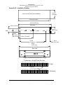
unit aside in a safe location until needed. Install the tray using six clip nuts (475-630-0002), and six FHP 632 x ½" screws (475-632-0012). The audio selector panel must be supported at front and rear of the mounting tray.
2.3.4
Tray and Connector Assembly
The unit connectors mate directly with the circuit boards in the PMA7000M-S. The connectors are a Molex
crimp-type, and require the use of a Molex hand crimp tool, EDP P/N 11-01-0203, CR6115B (or equiv.).
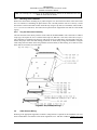
The connectors are mounted to the unit tray with #4-40 screws (475-440-0007), from the inside of the tray.
Ensure that proper strain relief and chafing precautions are made during wiring and installation, using the
cable clamp (625-001-0002). Secure the ground bar (430-630-0002), if desired using, #6-32 nuts (475-6320003) and #6-32 lock nuts (475-632-0004).
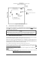
Figure 2-1 Tray Assembly Drawing
2.4
Cable Harness Wiring
Referring to the appropriate Appendix, assemble a wiring harness as required for the installation. All wires
must be MIL-SPEC in accordance with current regulations. Two- and three-conductor shielded wire must
200-070-0012
Page 2-2
Rev. 12, Sept. 2000
PS Engineering
PMA7000M-S Series Audio Selector Panel and Intercom System
Installation and Operator’s Manual
be used where indicated, and be MIL-C-27500 or equivalent specification. Proper stripping, shielding and
soldering technique must be used at all times. It is imperative that correct wire be used.
Refer to FAA Advisory Circular 43.13-2A for more information. Failure to use correct techniques may result in improper operation, electrical noise or unit failure. Damage caused by improper installation will void
the PS Engineering warranty.
NOTE: PS Engineering can make a custom wiring harness for the intercom portion. Call 1-800-ICS-AERO
or see www.ps-engineering.com for details.
2.4.1
Noise
Due to the variety and the high power of radio equipment often found in today's general aviation aircraft,
there is a potential for both radiated and conducted noise interference.
The PMA7000M-S power supply is specifically designed to reduce conducted electrical noise on the aircraft power bus by at least 50dB. Although this is a large amount of attenuation, it may not eliminate all
noise, particularly if the amplitude of noise is very high. There must be at least 13.8 VDC present at the
bottom connector, pin 20, of the PMA7000M-S for the power supply to work in its designed regulation.
Otherwise, it cannot adequately attenuate power line noise. Shielding can reduce or prevent radiated noise
(i.e., beacon, electric gyros, switching power supplies, etc.) However, installation combinations can occur
where interference is possible. The PMA7000M-S was designed in a RFI hardened chassis and has internal
Electromagnetic Interference (EMI) filters on all inputs and outputs.
Ground loop noise occurs when there are two or more ground paths for the same signal (i.e., airframe and
ground return wire). Large cyclic loads such as strobes, inverters, etc., can inject noise signals onto the airframe that are detected by the audio system. Follow the wiring diagram very carefully to help ensure a
minimum of ground loop potential. Use only Mil Spec shielded wires (MIL-C-275000, or better).Under no
circumstances combine a microphone and headphone wiring into the same shielded bundle. Always use a 2or 3-conductor, shield wire as shown on the installation wiring diagram.
Radiated signals can be a factor when low level microphone signals are "bundled" with current carrying
power wires. Keep these cables physically separated. It is very important that you use insulated washers to
isolate the ground return path from the airframe to all headphone and microphone jacks.
Adding a high-performance audio control system, particularly in conjunction with high-performance active
noise canceling headsets, cannot improve on older avionics that were designed for cabin-speaker use. PS
Engineering makes no claim that the audio panel will provide a noise-free audio quality under all installation conditions, particularly with older avionics.
2.4.2
Existing KMA-24 Installation
If the installation replaces a KMA-24 (series -01, -02 or -03), the existing 44 pin connector can be used for
the bottom connector of the PMA7000M-S tray as is, providing it is properly installed and wired. No other
changes are required except for external marker lights (see Section 3.7.2 for details). The "key" in the existing connector must be located between pins 7 and 8. This connector will be used in the bottom connector
position. (See Appendix for complete wiring harness details.)
The existing ground bus may be reused for radio shield connections, if it was constructed so it can be relocated to the PMA7000M-S tray.
2.4.3
Existing PMA6000 installations
In 28-Volt aircraft, the dropping resistor may be removed, however, the 2 Amp breaker should be changed
to 3 Amp. If both old unit is stereo (PMA6000S or PMA6000MS), no rewiring is necessary unless additional features are added.
2.4.3.1
Stereo PMA7000M-S installations into monaural PMA6000, PMA6000M.
Installations replacing PMA6000 or PMA6000M require re-wiring of the top connector to accommodate the
stereo configuration. See appendixes for detailed interconnect information.
200-070-0012
Page 2-3
Rev. 12, Sept. 2000
PS Engineering
PMA7000M-S Series Audio Selector Panel and Intercom System
Installation and Operator’s Manual
2.4.4
Power
The PMA7000M-S-Series are compatible with both 14 and 28 Volt DC systems. A two (2) Amp circuit
breaker is required for 14 VDC installations, and a three (3) Amp breaker for 28 VDC aircraft. Power and
ground wires must be a twisted #18 AWG pair. Connect airframe power ground to J1 (bottom connector)
Pin Z only. No dropping resistors are required.
2.4.5
Communications Push-to-Talk
An important part of the installation is the PTT (Push-To-Talk) switches that allow the use of your aircraft
communications radio for transmissions. There are three typical configurations that can be used. Select the
case that best fits the installation. Only the person who presses their PTT switch will be heard over the radio. If the pilot and copilot both use the PTT, the only pilot position has access to the radio. The pilot position will have PTT control regardless of the mic selector switch or copilot PTT when the PMA7000M-S is
in the OFF/EMG mode.
CASE I: PTT is built into both pilot and copilot yokes.
CASE II: PTT is in pilot yoke only. This configuration requires a modified external PTT switch plugged
into the copilot's microphone jack. (See Appendix A). When the copilot's PTT is pressed, the intercom
switches the microphone audio from pilot to copilot mic.
CASE III: No built in PTT. This requires two built in PTTs to be installed, or modified external PTT
switches to be used. Modify external PTT as required. See Appendix A.
2.4.6
Audio Panel interface
The PMA7000M-S is designed to interface with standard aircraft avionics, and presents a 500Ω receiver
impedance. For best results, a twisted-shielded cable is recommended from the avionics audio source to the
audio panel, with the shield grounded at the audio panel end.
Some avionics do not provide a separate audio low, and may introduce additional electrical noise into the
system. For best results, connect the audio low from the audio panel to the radio ground, using one conductor of the twisted-shielded cable.
2.4.6.1
Speaker Load
The PMA7000-series contains a speaker amplifier. Some units with internal speaker amplifiers, such as the
King Radio KX170-series, require a resistive load to prevent damage if their speaker amplifier is not used.
Connect the speaker output from the unit to the load input on the PMA7000M-S (J1, pins 19 and L, 16 and
M. The speaker load in 16 Ω, 3W.
2.4.7
Com 3 Audio
As installed in the standard configuration, the PMA7000M-S Com 3 audio is placed in the audio when the
mic selector switch is in the Com 3 position (fully CCW). Pushing the receiver selector buttons can monitor
Com 1 and Com 2 audio. If monitoring of Com 3 is desired in the Com 1 or Com 2, connect Com 3 audio in
parallel to the AUX input (J1, pin 11).
2.4.8
Transmit Interlock
Some communications transceivers use a transmit-interlock system. To fully utilize the Split Mode feature,
this function must be disabled. Consult that manufacturer's installation manual.
2.4.9
"Swap" Mode
When a momentary, normally open, push-button switch is connected between pin 10 on the top connector
and aircraft ground, the user can switch between Com 1 and 2 by depressing this switch without having to
turn the mic selector switch. This yoke-mounted switch eliminates the need to remove your hands from the
yoke to change transceivers.
200-070-0012
Page 2-4
Rev. 12, Sept. 2000
PS Engineering
PMA7000M-S Series Audio Selector Panel and Intercom System
Installation and Operator’s Manual
2.4.10 Backlighting
The PMA7000M-S has an automatic dimming of the pushbutton annunciator LEDs and marker lamps controlled by a photocell. Control of the unit backlighting is through the aircraft avionics dimmer. Connect the
dimmer control line to J1 pin D for 14 volt systems, and to J1 pin F for 28 volt systems. Pin E is light
ground.
If an external dimmer control is not used, a constant low level back light illumination can be established for
nighttime viewing. Pin D or F (depending on system voltage) must be tied to power (J1, pin 20) for the back
lighting system to work. The photocell mounted in the unit face will automatically adjust the intensity of the
push-button annunciator LEDs.
2.4.11 Unswitched inputs
J1, pin T is the unswitched input number 1 and J1 pin 17 is unswitched input 2. These inputs are presented
to the pilot and copilot regardless of the audio configuration, and will always mute the entertainment inputs.
These 510Ù inputs can be used for altimeter DH audio, GPS waypoint audio, autopilot disconnect tones,
air-to-ground (Flitefone) telephone ringer or any other critical audio signal. This input is not related to the
cellular telephone interface.
2.4.12 PA Mute (J1, Pin 18)
Pin 18 of J1 is a TTL logic output that is pulled low during PTT operation. This serves as an input to external public address system to prevent feedback during transmissions.
2.4.13 Public Address Function (J2, Pin 18)
A PMA7000MS with serial numbers above “D” for the top board (second set of serial numbers) has a Public Address function. By connecting the top connector (J2), Pin 18 to ground, the pilot’s microphone audio
is placed on the cabin speaker output. When the pilot’s PTT is activated, his voice is heard over the
speaker. The copilot can continue to use the selected com.
We recommend installing a toggle switch to connect the cabin speaker output (pin W, bottom connector) to
a rear or public address speaker instead of the cockpit speaker close to the pilot. This will prevent feedback.
2.4.14
Control Output (J2, Pin A)
Pin A of the top connector is pulled to ground whenever the AUX button is depressed. This serves as a
control line for external devices, such as a entertainment system that the pilot wishes to control.
This could be used in conjunction with a PA to control J2, Pin 18, as well as an external relay to change to
the cabin speaker from the cockpit.
2.4.15 Intercom wiring
The top connector (J2) is for the intercom and additional functions. See Appendix for intercom connection
configurations. It is critical to the proper operation of this system to have this connector wiring made in
accordance with these diagrams. Use 2- and 3-conductor, MIL-spec cable as shown. Connect the shields at
the audio panel end only, and tie to the audio low inputs as shown.
NOTE: The top connector harness can be custom made by PS Engineering, Inc. Simply call the factory and
obtain a wire harness work-sheet. The harness will be made to your specifications and fully functionally
tested. All hardware is included.
2.4.15.1 Entertainment Input
NOTE: Use the low level output of any entertainment device to connect to the audio
panel. Maximum signal level is 2 VAC p-p.
DO NOT use a speaker-level output, this will cause internal damage in the audio panel.
2.4.15.1.1 Stereo entertainment (7000S, 7000MS)
200-070-0012
Page 2-5
Rev. 12, Sept. 2000
PS Engineering
PMA7000M-S Series Audio Selector Panel and Intercom System
Installation and Operator’s Manual
Two stereo entertainment devices (CD player, cassette player, etc.) can be connected to the unit. Install two
1
/8-inch stereo jacks in a convenient location so that the pilot can plug in the entertainment devices into the
system. The audio signal at the entertainment input must be a minimum of 500 mV P-P per channel for optimum music performance.
PS Engineering offers an aviation Compact Disk layer, the PCD7100 (Part Number 11952), designed to
interface with the PMA7000-Series.
All entertainment devices must be switched off for both takeoff and landing.
2.4.15.1.2 Entertainment distribution
Entertainment source #1 provides music for the pilot and copilot positions, while entertainment source #2
provides music for the four passenger positions. The PMA7000M-S-system incorporates a "Soft Mute"
system. This will mute the entertainment devices during ICS or radio conversation.
Any signal appearing in the unswitched audio inputs will always mute the entertainment sources, even
though the passengers may not hear the audio tone itself.
Entertainment inputs #1 and #2 can be paralleled so a single entertainment source can serve both the passengers and the crew. It is suggested however, that a switch (DPDT) is installed between the single entertainment device and entertainment input #1. This will allow the pilot and copilot to decide if they hear entertainment while in the Crew mode.
Caution: Local oscillators and internal signals from some entertainment equipment can cause undesired
interference with other aircraft systems. Before takeoff, operate the entertainment devices to determine if
there is any adverse effect within the aircraft systems. If any unusual operation is noted in flight, immediately switch off the entertainment devices.
All entertainment devices must be switched off for both takeoff and landing.
2.4.15.1.3 Entertainment 2 Mute (Pin V)
The ICS button on the PMA7000M-S controls the muting (“Karoake mode”) of entertainment source #1.
Connecting J2 pin V to ground through a SPST switch places the entertainment #2 music source into the
Karoake Mode. In this mode, incoming music and intercom conversation will not mute the music for the
passengers’ intercom net. This allows uninterrupted music during casual conversation and at times when
radio communications are of lessor importance.
2.4.16 VOX Override (J2, Pin U)
Normally not connected. Connecting pin U of the PMA7000M-S of J2 to ground will force the IntelliVox®
open. This can be hooked up as a hot mic switch which will place all microphones on the intercom. This can
also be connected through a momentary switch to serve as a VOX test switch, if desired. Because the IntelliVox® will close in the presence of a steady tone, this pin is used in testing to defeat the IntelliVox® software.
2.4.17 Intercom expansion (J2, Pins P, S, and C)
The PMA7000M-S contains a 6-place intercom. In applications where more intercom positions are needed,
PS Engineering can provide intercom expansion units, such as the PM2CREW, part number 11919,
11919R, etc. These can add up to eight additional stereo intercom stations, plus independent music input.
Interface to the expansion unit is through J2, pins P (audio input from expansion unit), S (audio output to
expansion unit) and C (9 VDC expansion power).
2.4.18 Playback button Installation (J2, Pin 19- Options 1, 2 and 7 ONLY)
To activate the Recording System playback, a momentary push button switch is required. This switch can be
located anywhere in cockpit convenient to the pilot's reach. The switch must be connected to pin 19 of J2 of
the PMA7000M-S, and ground
200-070-0012
Page 2-6
Rev. 12, Sept. 2000
PS Engineering
PMA7000M-S Series Audio Selector Panel and Intercom System
Installation and Operator’s Manual
2.4.19 Audio Message Acknowledge (J2, Pin W) Option 1 and 2 only)
The audio message installation requires inputs from an external annunciator, such as an Electronics International engine gage system. A falling edge (input pulled low) when applied to the appropriate pin of the connector will cause the message to be played, repeating every two seconds, until the acknowledge (“ACK”)
button is pushed.
Install the “ACK” button in a location convenient to the pilot and copilot position. This switch is a momentary SPST switch between J2 Pin W and ground.
The following table contains information regarding various inputs.
Function EGT or CHT
Fuel
Oil PresVolt/
Flow or
sure or
Amp
Level
temperature
PMA7000 Pin
Z
22
Y
21
Message Number
1
2
3
4
Option 1
Message Text
“Check tem- “Check “Check
“Check
perature”
fuel”
oil”
battery”
RPM
Manifold
Pressure
X
5
20
6
“Check engine speed”
“Check boost”
Other combinations can be created at additional cost.
NOTE: PS Engineering can only provide input information at this time. Approval basis is the responsibility
of the installer. Contact PS Engineering for more information.
2.5
Marker Beacon Installation
The marker beacon receiver is an option included in the PMA7000M-S. Non-marker (PMA7000S) units
can provide audio interface with the external receiver (see section 2.5.4).
2.5.1
Marker Antenna Installation
A marker beacon antenna, appropriate to the type and speed of the aircraft, is required (not included). Refer
to aircraft and antenna manufacturer's installation instructions, as well as AC43.13-2A (or later revision),
Chapter 3, for information on proper antenna installation techniques. The marker beacon antenna must be
mounted on the bottom of the aircraft.
2.5.2
External Marker Lights (7000MS)
For installations that require external marker beacon lights, there are three outputs that can drive 12-Volt
lamps only. The external output lamps are driven high (typically +9 VDC ±1.5 VDC unloaded, at MAX
brightness) when active. Maximum source current per lamp is 125 mA. Voltage varies with photocell dimming.
2.5.3
Middle Marker Sense (7000MS)
A Middle Marker Sense output signal is available from the 7000M-S to flight control systems. This function
will not operate during the test mode. This output will go to +4.5 VDC (± 1.0 VDC) when a valid Middle
Marker signal is received. This output is J1, pin 2.
2.5.4
Marker Audio Input (7000S)
If using an external marker receiver, the audio input is J1, pin 21 (MKR input).
2.6
Adjustments
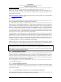
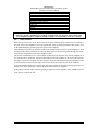
The PMA7000M-S is factory adjusted to accommodate the typical requirements for most aircraft configurations. There are five adjustments however, that will allow the installer to tailor the specific functions.
200-070-0012
Page 2-7
Rev. 12, Sept. 2000
PS Engineering
PMA7000M-S Series Audio Selector Panel and Intercom System
Installation and Operator’s Manual
Marker Gain
CW- Reduce
223
Passenger Volume
CCW Increases
133
211
231
PMA7000M-S adjustment holes
111
Front of Unit
MKR Low Sense
CW Decrease Sens.
Not used
Speaker Volume
CW-Increase
Marker Audio
CW Decrease Volume
Figure 2-2- PMA7000M-S Adjustments
2.7
Communications Antenna Installation Notes
For best results while in Split Mode, it is recommended that the one VHF communications antenna is located on top of the aircraft while the other communications antenna is installed on the bottom. Any antenna
relocation must be accomplished in accordance with AC 43.13-2A, aircraft manufacturers’ recommendations and FAA-approved technical data.
Warning:
It is probable that radio interference will occur in the split mode when the frequencies of the two aircraft
radios are adjacent, and/or the antennas are physically close together. PS Engineering makes no expressed or implied warranties regarding the suitability of the PMA7000M-S in Split Mode.
2.8
Wireless telecommunications interface
The PMA7000M-S has interface capability with units such as the AirCell AGT.01. It is the user’s responsibility to determine the appropriate legal use of the equiment, and provide the services.
Interface to the AirCell, or any telecommunications device, is through the J1 (bottom) connector, pins 14
and N. Pin 14, labeled cellphone ring, is connected to pin V of the AirCell connector and pin N of J1 is
connected to pin W. The shield is terminated to pin K on the AirCell. On the AirCell interface these are
listed as data/fax lines, but they are used for voice interface in this case.
Use a 2-conductor with shield cable, and connect the shield to Pin K of the AirCell.
If interface is desired with another type of wireless telecommunications unit, the aircraft owner can purchase an after-market interface cable. By Federal Communications Commission (FCC) regulations, these
can only be used on the ground in the United States.
PS Engineering makes no expressed or implied warranty that the equipment will be compatible with any
devices other than AirCell.
Some interface cables are available from MobileQuest at 800-882-1288, or (215) 734-7000. The following
is a partial list of available interface cables:
Compatible Phones
200-070-0012
Page 2-8
Rev. 12, Sept. 2000
PS Engineering
PMA7000M-S Series Audio Selector Panel and Intercom System
Installation and Operator’s Manual
Audiovox Series 5
Motorola TeleTAC, DPC 550, DPC65-, Lite Series, Profile Series
Motorola Elite, M70, M75, SC-725
Motorola Bag Phones, Mobiles
NEC100 Series, 110, 120, 180, Sport
NEC 700 & 800 Series
OKI 900/910, AT&T 3730/3710
OKI 1150/1145, AT&T 3760
Fujitsu PCX
Mitsubishi 4000, DiamondTel 22X/20X/18X
NEC960
NEC DT2000 Digital Phone
Unauthorized use of cellular telephone devices in aircraft is subject to FCC enforcement action,
which may include a $10,000 fine per incident. PS Engineering, Inc. does not endorse using unapproved cellular telephone equipment in flight, and takes no responsibility for the user’s action.
2.8.1
Hook Switches
While the mic selector acts as the hook switch for the pilot, additional hook switches must be installed to
have full access to the cellphone system. The copilot hook switch is a SPST switch that connects pin L of J2
on the PMA7000M-S to ground to place the copilot on the cellphone.
PMA7000M-S J2, pin M is the passenger hook switch. Install a SPST switch in a location adjacent to each
passenger headset where cellphone use is desired. When pin M is connected to ground through any switch,
the passenger microphones are all on the cellphone system.
The wireless communication “tel” system utilizes an intercom loop. Therefore, any time the cellphone is in
use from the pilot or copilot side, pilot and copilot will lose intercom capability. In the ALL mode, when the
passengers’ activate the cell phone, the pilots will have intercom, and continue to hear and transmit over the
avionics normally. However the passengers will not have intercom, because they are on the telephone.
To prevent unwanted distractions, only the pilot and copilot will hear an incoming call ring signal. They can
then decide to allow a passenger to activate the hook switch and use the telephone.
If the pilot has selected “TEL” mode, the passengers cannot access the telephone in the “CREW” intercom
mode, but they will hear the call.
200-070-0012
Page 2-9
Rev. 12, Sept. 2000
PS Engineering
PMA7000M-S Series Audio Selector Panel and Intercom System
Installation and Operator’s Manual
2.9
PMA7000M-S Pin assignments (Standard Version Only)
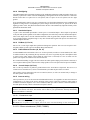
J1 Bottom Connector
Chassis Ground
MKR Coax Shield
MM Sense Output
MKR Antenna
Pilot Headphones (rt)
White Lamp Output
Amber Lamp Out
14 V Light Hi
Blue Lamp Out
Light Lo
DME Audio Hi
28V Lights Hi
Com 2 Mic Audio Hi
Pilot Mic Audio Hi In
Com 3 Audio Hi
Com 1 Audio Hi
Com 3 Mic Audio Hi
Com 2 Audio Hi
Com 1 Spkr Load
AUX Audio Input Hi
Com 2 SPKR Load
Nav 1 Audio Hi
Cellphone Tie B
Nav 2 Audio Hi
Com 1 Mic Audio Hi
Cellphone Tie A
Com 1 Mic Key
Com 3 Mic Key
ADF Audio Hi
Com 2 SPKR load
Unswitched Audio In #1
Unswitched Audio In #2
PA Mute
Com 2 Mic Key
Com 1 SPKR load
Cabin Spkr Out
Aircraft Power 11-33 VDC
Ext. Marker Audio Hi
Pilot Mic PTT
Cabin Spkr Lo
Aircraft Ground
1
A
2
B
3
C
4
D
5
E
6
F
7
H
8
J
9
K
10
L
11
M
12
N
13
P
14
R
15
S
16
T
17
U
18
V
19
W
20
X
21
Y
22
Z
J2 Top Connector
1
A
2
B
3
C
4
D
5
E
6
F
7
H
8
J
9
K
10
L
11
M
12
N
13
P
14
R
15
S
16
T
17
U
18
V
19
W
20
X
21
Y
22
Z
Pilot Phone Audio Hi (Left)
AUX Control Out
Copilot Phone Audio (Lt)
Copilot Phone Audio Lo
Copilot Phone Audio (Rt)
Expansion Power Out (+9 VDC)
Pass 1 Mic Audio Hi
Pass 1 Mic Audio Lo
Pass 2 Mic Audio Hi
Pass 2 Mic Audio Lo
Pass 3 Mic Audio Hi
Pass 3 Mic Audio Lo
Pass 4 Mic Audio Hi
Pass 4 Mic Audio Lo
Copilot Mic Audio Hi
Copilot Mic PTT
Copilot Mic Audio Lo
Swap Switch
Copilot Cellphone Off Hook
Passenger Headphone Audio (R)
Pass Cellphone Off Hook
Passenger Audio (L)
Passenger Headphone Audio Lo
Entertainment #2 in (R)
Expansion Input
Entertainment #2 In (L)
Ent. # 2 Low
Entertainment #1 In (R)
Expansion Output
Entertainment #1 Input (L)
Ent. #1 Input Lo
Ground
IntelliVOX Over ride
PA Activate
Mute 2
Playback
Message Acknowledge
Message 6 Play
Message 5 Play
Message 4 Play
Message 3 Play
Message 2 Play
Message 1 Play
Input
Output
200-070-0012
Page 2-10
Rev. 12, Sept. 2000
PS Engineering
PMA7000M-S Series Audio Selector Panel and Intercom System
Installation and Operator’s Manual
2.10
Post Installation Checkout
After wiring is complete, verify power is ONLY on pin 20 of the J1 (bottom connector), and airframe
ground on bottom connector pin Z. Failure to do so will cause serious internal damage and void PS Engineering's warranty.
2.11
Unit Installation
To install the PMA7000M-S, gently slide the unit into the mounting rack until the hold-down screw is engaged. While applying gentle pressure to the face of the unit, tighten the 3/32" hex-head in the center of the
unit until it is secure. DO NOT OVER TIGHTEN.
Warning: Do not over-tighten the lock down screw while installing the unit in tray.
Internal damage will result.
2.11.1 Operational Checkout
NOTE: The IntelliVox® is designed for ambient noise levels of 80 dB or above. Therefore some clipping
may occur in a quiet cabin, such as without the engine running, in a hangar. This is normal.
1.
2.
3.
4.
5.
6.
7.
8.
9.
10.
11.
12.
13.
14.
15.
16.
17.
18.
Apply power to the aircraft and avionics.
Plug headsets into the pilot, copilot, and occupied passenger positions.
Verify fail-safe operation by receiving and transmitting on com 1 from the pilot position, with the audio
panel power off. The Com audio will be present in the right ear cup only.
Switch on the unit by pressing the volume (VOL) knob.
Check intercom operation.
Rotate the Mic Selector Switch to the Com 1 position.
Verify that the Com 1 button lights. Verify that the green transmit LED (Light Emitting Diode) near the
mic selector is not illuminated. If the LED is on, stop testing and troubleshoot the microphone PTT installation.
Verify proper transmit and receive operation from the copilot position, noting that the copilot PTT
switch allows proper transmission on the selected transceiver.
Verify that pushing the COM 2 button causes the button to illuminate, and the Com 2 receiver to be
heard. Verify operation on Com 1 from the pilot position.
Repeat for Com 2 and Com 3, (if installed).
Rotate the mic selector switch to the COM 1/2 position. Verify that the pilot communicates on Com 1
and the copilot on Com 2.
Rotate the mic selector switch to the COM 2/1 position. Verify that the pilot communicates on Com 2
and the copilot on Com 1.
Rotate the mic selector switch to the TEL position. Verify that the pilot headset is connected to the cellular telephone system (if installed). Verify that by using the pilot side PTT, the pilot can transmit on
Com 1. The copilot has no transmit capability in TEL mode.
Verify proper operation of all receiver sources by selecting them using the button. Note that the button
for the receiver sources stays in, and the button illuminates to show which source is in use.
Push in the SPR button. Verify that all selected audio is heard in the cockpit speaker. Verify that the
audio mutes when the mic is keyed.
Verify that the LED in the lower right side illuminates when either push to talk is keyed.
Verify proper Intercom system operation in the ALL, ISO and CREW modes (see Table 3-1).
Verify that the audio selector panel system does not adversely affect any other aircraft system by systematically switching the unit on and off, while monitoring the other avionics and electrical equipment
on the aircraft.
200-070-0012
Page 2-11
Rev. 12, Sept. 2000
PS Engineering
PMA7000M-S Series Audio Selector Panel and Intercom System
Installation and Operator’s Manual
2.11.1.1
Marker Checkout (7000M-S only)
1.
Connect a ramp generator at the antenna end of the marker coax. With the unit under test in HI sensitivity, verify that a 160 µV, modulated 95% with 1300 Hz, signal will illuminate the amber (M) marker
light, and that marker audio is present in the headphones when the Marker Audio (M) push-button has
been depressed. Select SPR for speaker to verify marker audio availability on the cabin speaker. Verify
that the white (I) and blue (O) lights will illuminate within ± 3dB of the amber lamp, with 3000 HZ and
400 Hz applied, respectively.
2.
3.
Repeat with the unit in LOW sensitivity, with 430 µVolts applied.
Connect the marker antenna and verify proper operation.
2.11.2 Receiver Sensitivity
Although the PMA7000M meets FAA TSO-C35d sensitivity specifications, the sensitivity of the receiver
has been adjusted to meet real world requirements (150µV and 430µV, soft). This will usually eliminate the
need for the avionics shop to reduce the sensitivity in the field so as to prevent early detection of the marker
beacons. If your particular installation requires more or less sensitivity, see adjustment section 2.6, and figure 2-1.
2.12
Cellular Interface Checkout
When a wireless telecommunication system is installed and configured, a dial tone will appear in the headset of the pilot when the mic selector is in the “Tel” position. In “ALL” intercom mode, a dial tone will be
heard whenever the copilot or passenger’s hook switch is closed.
2.13
Internal Recorder Checkout (Optional)
With headset plugged into pilot’s side jacks, tune COM 1 to local frequency, such as FSS or ATC ground.
Select Com 1 on mic selector switch, and record at least five incoming radio transmissions.
This audio should only appear in the pilot’s headset, and only be incoming transmissions from the transceiver selected in the mic select switch.
Depress the panel or yoke mounted playback switch, and verify that messages play, in the order received.
Repeat for COM 2, and COM 3 (if installed).
2.14
Digital Annunciation Checkout (Optional)
If interfaced with an annunciation system, verify that all alert messages play at the appropriate time, and that
they are silenced by the “ACK” button.
2.15
Final Inspection
Verify that the wiring is bundled away from all controls and no part of the installation interferes with aircraft control operation. Move all controls through their full range while examining the installation to see
that no mechanical interference exists. Verify that the cables are secured to the aircraft structure in accordance with good practices, with adequate strain relief. Ensure that there are no kinks or sharp bends in the
cables and coaxial cables. Verify that the cables are not exposed to any sharp edges or rough surfaces, and
that all contact points are protected from abrasion.
Complete log book entry, FAA Form 337, weight and balance computation and other documentation as
required. Sample text for FAA Form 337, and instructions for continuing airworthiness can be found in Appendix F.
Return completed warranty registration application to PS Engineering.
200-070-0012
Page 2-12
Rev. 12, Sept. 2000
PS Engineering
PMA7000M-S Series Audio Selector Panel and Intercom System
Installation and Operator’s Manual
Section III OPERATION
GENERAL INFORMATION
3.1
SCOPE
This section provides detailed operating instructions for the PS Engineering PMA7000M-S, and
PMA7000S Audio Selector Panel/Intercom Systems. Please read it carefully before using the equipment so
that you can take full advantage of its capabilities.
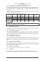
This section is divided into four sections covering the basic operating areas of the PMA7000M-S systems.
They are Audio Selector, Transceiver Selection, Intercom, and Marker Beacon Receiver (7000M-S only).
Receive Audio Selectors
Marker Mode Selector
Marker Indicator Lamps
O M
I
V
O
L
PUSH
OFF/EMG
HI
LO
T/M
Com 1
Mic Selector
Photo
Detector
Nav 1
MKR
ADF
DME
COM 1
COM 2
COM 3
ISO Com
ALL
CREW
2
Nav 2
ICS
ENGINEERING R
INCORPORATED
Mounting
Screw
AUX
PMA7000M-S
Crew ICS/
Music 1 Mute
COM 1/2
COM 2/1
TEL
SPR
Transmit
Swap
Speaker Switch
Intercom Mode Sel.
TX Indicator
Swap Indicator
Intercom Vol.
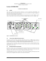
Figure 3-1 PMA7000M-S controls
3.2
Power Switch (EMG-Fail Safe Operation)
Unit power is turned on and off by pushing the volume knob. In the OFF or "EMG" position, the pilot is
connected directly to Com 1. This allows communication capability regardless of unit condition. Any time
power is removed or turned OFF, the audio selector will be placed in the fail-safe mode.
The power switch also controls the audio selector panel functions, intercom, and marker beacon receiver,
(PMA7000M-S only). Unless the mic selector is in Com 3 mode, at least one of the selected audio LEDs
will be on (Com 1 or Com 2).
3.3
Microphone Selector (All models)
When the mic selector switch is in the Com 1 position, both pilot and copilot will be connected to the Com l
transceiver. Only the person who presses their Push To Talk (PTT), will be heard over the aircraft radio.
Turning the rotary switch to the COM 2 position will place pilot and copilot on Com 2.
The PMA7000M-S gives priority to the pilot’s PTT. If the copilot it transmitting, and the pilot presses his
PTT, the pilot’s microphone will be heard over the selected com transmitter.
200-070-0012
Page 3-1
Rev. 12, Sept.2000
PS Engineering
PMA7000M-S Series Audio Selector Panel and Intercom System
Installation and Operator’s Manual
Turning the mic selector fully counterclockwise places the pilot and copilot on Com 3. Com 3 receive audio
is automatically placed in the headset (and speaker if selected). Com 1 and/or Com 2 receiver audio can be
selected to monitor those transceivers.
The PMA7000M-S-Series has an automatic selector mode. Audio from the selected transceiver is automatically heard in the headsets and speaker. You can check this function by switching from COM 1 to COM 2
and watch the selected audio light on the selector change from COM 1 to COM 2. This ensures the pilot
will always hear the audio from the transceiver he is transmitting on.
When switching the mic selector rotary switch from COM 1 to COM 2, while COM 2 audio had been selected, Com 1 audio will continue to be heard. This eliminates the pilot having to switch Com 1 audio back
on, if desired.
When switching from COM 1 to COM 2 while Com 2 has NOT been selected, Com 1 audio will be switched
off. In essence, switching the mic selector will not effect the selection of Com audio.
The “TEL” position, fully CW on the mic selector switch, is the pilot’s “hook” switch, when the system is
interfaced to an appropriate approved wireless telecommunication system, such as the AirCell system.
Placing the mic selector in TEL placed the pilot microphone and headphones on the cellphone. The pilot
PTT will switch the pilot mic to the COM 1, and allow continued aircraft communications as well.
The copilot will also be able to transmit on COM 1 with his PTT as well.
NOTE: Placing the mic selector switch in the TEL position will disable pilot and copilot intercom, as the
intercom circuit is transferred to the telephone use. In crew or ISO mode, placing the switch in TEL mode
removes the passengers access to the telephone.
3.3.1
Swap Mode (Switch from Com 1 to Com 2 remotely)
With a yoke mounted, momentary switch, the pilot can change from the current Com transceiver to the other
by depressing this switch. When "Swap Mode" is active, an annunciator in the lower right corner of the unit
will illuminate, indicating that the Mic Selector switch position is no longer current. To cancel "Swap
Mode," the pilot may either press the yoke mounted switch again, or turn the Mic Selector Switch to the
Com that is active.
3.4
Audio Selector (All models)
Receiver audio is selected through two momentary and six latched, push-button, backlit switches. Com 1
and Com 2 are the momentary switches.
Because the rotary microphone selector switch controls what transceiver is being heard, the Com l and Com
2 push-buttons are of the momentary type and do not remain in when selected. This is also part of the "auto”
function. You will always hear the audio from the transceiver that is selected for transmit by the rotary mic
selector switch.
The users can identify which receivers are selected by noting which of the green switch LEDs are illuminated. Push buttons labeled Nav 1, Nav 2, DME, MKR (Marker), ADF, AUX (auxiliary), and SPR
(Speaker) are "latched" type switches. When one of these buttons is pressed, it will stay in the "in" position.
Press the switch again and it be in the "out" position and remove that receiver from the audio.
3.4.1
Speaker Amplifier
The "SPR" in the push-button section stands for speaker. This switch will place all selected audio on the
cockpit speaker when this switch is selected. NOTE: Except for the unswitched audio, the speaker amplifier
is not active in the "Split Mode."
Unswitched audio, (autopilot disconnect, altimeter warning, etc.) will come through the speaker regardless
of the speaker button position.
200-070-0012
Page 3-2
Rev. 12, Sept.2000
PS Engineering
PMA7000M-S Series Audio Selector Panel and Intercom System
Installation and Operator’s Manual
3.4.1.1
Public Address Function
In PMA7000MS versions above “F” serial number for the top board (2nd set of unit serial numbers) a public
address function was added. To access this function, a switch is installed to connect the top connector, pin
18, to ground. This places the pilot microphone on the speaker output (Pin W) when the PTT is pushed. The
copilot can continue to use the selected com radio.
We recommend that the switch transfer the audio from the cockpit speaker to a cabin speaker for public
address. This will prevent feedback.
3.4.2
Key “Click”
The PMA7000M-S is equipped with a “click” function that provides an aural feedback to the user in addition to the tactile button push. This sound can be enabled or disabled by simultaneously holding the COM 1
and COM 2 buttons in for at least 5 seconds. Any person hearing the radios will also hear the key click.
Allow at least 20 seconds between turning the key click on and off.
3.5
Split Mode
Turning the rotary switch to COM 1/COM 2 places the PMA7000M-S into "Split Mode." This places the
pilot on Com 1 and the copilot on Com 2. An example of this useful feature is when the pilot may want to
talk to Air Traffic Control, while the copilot may be speaking to Flight Watch. Although this mode has
limitations (see below) we believe you will find this to be a useful feature.
Switching to Com 2/Com l will reverse the “Split Mode” radio selection. The pilot will be on Com 2 and
the copilot will be on Com 1.
Note:
Due to the nature of VHF communications signals, and the size constraints in general
aviation aircraft, it is probable that there will be some bleed-over in the Split mode, particularly on adjacent frequencies.
PS Engineering makes no warranty about the suitability of Split Mode in all aircraft conditions.
Note: Split Mode does not turn off other (Nav, ADF, etc.) selected audio to pilot. However, the copilot will only hear
the selected communications receiver.
3.5.1
Split Mode ICS
In split mode, the pilot and copilot are usually isolated from each other on the intercom, simultaneously
using their respective radios. Depressing the ICS button in Split Mode will activate VOX intercom between
the pilot and copilot positions. This permits intercommunication when desired between the crew. Pressing
the ICS button again disables this crew intercom function.
3.6
Intercom Operation
3.6.1
IntelliVox® VOX-Squelch
No adjustment of the IntelliVox® squelch control is necessary. There is no field adjustment. Through three
individual signal processors, the ambient noise appearing in all six microphones is constantly being sampled. Non-voice signals are blocked. When someone speaks, only their microphone circuit opens, placing
their voice on the intercom.
The system is designed to block continuous tones, therefore people humming or whistling in monotone may
be blocked after a few moments.
200-070-0012
Page 3-3
Rev. 12, Sept.2000
PS Engineering
PMA7000M-S Series Audio Selector Panel and Intercom System
Installation and Operator’s Manual
For consistent performance, any headset microphone must be placed within ¼-inch of your lips,
preferably against them. (ref: RTCA/DO-214, 1.3.1.1 (a)).
It is also a good idea to keep the microphone out of a direct wind path. Moving your head through
a vent air stream may cause the IntelliVox® to open momentarily. This is normal.
The IntelliVox® is designed to work with normal aircraft cabin noise levels (70 dB and above). It
loves airplane noise! Therefore, it may not recognize speech and clip syllables in a quiet cabin,
such as in the hangar, or without the engine running. This is normal.
For optimum microphone performance, PS Engineering recommends installation of a Microphone Muff Kit
from Oregon Aero (1-800-888-6910). This will not only optimize VOX performance, but will improve the
overall clarity of all your communications.
Table 3-1 Mic Muff ™ Part Numbers
Manufacturer
Bose
David Clark
Lightspeed
Model
Dynamic
Electret
M87 Dynamic
H10-30
H10-20, H10-40
H10-13.4
15K & 20K
Peltor
7003
7004
90010
90015
Pilot
11-20 & 11-90
90015
Sennheiser
Telex
3.6.2
Mic Muff™ Part Number
90010
90015
90020
90010
90015
90015
90015
90015
Airman 750
AIR3000
90015
90010
Volume Control
The volume control knob adjusts the loudness of the intercom for the pilot and copilot only. It has no effect
on selected radio levels, music input levels or passengers' volume level.
Adjust the radios and intercom volume for a comfortable listening level for the pilot. Most general aviation
headsets today have built-in volume controls; therefore, passenger volume can be adjusted at the headset. If
desired, passenger volume level can be adjusted by a screwdriver adjustment at the top of the tray (see figure 2-1).
3.6.2.1 Mono headsets in Stereo Installation
All passenger headsets are connected in parallel. Therefore, if a monaural headset is plugged in to a
PMA7000M-S Stereo installation, one channel will be shorted. Although no damage to the unit will occur,
all passengers will lose one channel, unless they switch to the “MONO” mode on the headset. PS Engineering modifies headsets to add stereo capability, using high-fidelity speakers. Contact factory for details.
3.6.3
Intercom Modes
The lower switch on the left side is a 3-position mode switch that allows the pilot to tailor the intercom
function to best meet the current cockpit situation. The description of the intercom mode function is valid
200-070-0012
Page 3-4
Rev. 12, Sept.2000
PS Engineering
PMA7000M-S Series Audio Selector Panel and Intercom System
Installation and Operator’s Manual
only when the unit is not in the "Split" mode. Then, the pilot and copilot intercom is controlled with the ICS
button.
ISO: (Up Position): The pilot is isolated from the intercom and is connected only to the aircraft radio system. He will hear the aircraft radio reception (and sidetone during radio transmissions). Copilot will hear
passengers’ intercom and Entertainment 1, while passengers will hear copilot intercom and Entertainment 2.
Neither will hear aircraft radio receptions or pilot transmissions.
ALL: (Middle Position): All parties will hear the aircraft radio and intercom. Crew will hear Entertainment
1, passengers will hear Entertainment 2. During any radio or intercom communications, the music volume
automatically decreases. The music volume increases gradually back to the original level after communications have been completed.
CREW (Down Position): Pilot and copilot are connected on one intercom channel and have exclusive access
to the aircraft radios. They may also listen to Entertainment 1. Passengers can continue to communicate
with themselves without interrupting the Crew and also may listen to Entertainment 2.
Anytime the PMA7000M-S is in either the COM 1/COM 2, COM 2/COM 1 ("Split Mode"), the pilot and copilot intercom is controlled with the ICS button. The passengers will maintain intercommunications, but
never hear aircraft radios.
3.6.3.1
Entertainment Input
The audio selector panel has provisions for two separate entertainment input devices. They operate independently in the PMA7000M-S. The volume control does not affect music level.
While in the ISO (Isolate) mode, the copilot will hear Entertainment 1 while the four passengers will hear
Entertainment #2. The pilot will hear entertainment 1, at a muted level. In normal operation, whenever a
person speaks, or if the aircraft radio becomes active, the music will automatically mute and then will
gradually return to the original listening level when the intercom or radio conversation ceases.
When in the ALL mode, pilot and copilot will hear Entertainment 1 input while all passengers will hear the
Entertainment 2 source. While in the CREW mode, pilot and copilot will hear entertainment input #1 while
the passengers may listen to entertainment input #2.
It is also possible to use only one entertainment input device for both entertainment inputs. However, it is
suggested that a switch (DPDT) be installed between the single entertainment device and entertainment input #1. This will allow the pilot and copilot decide if they hear entertainment while in the Crew mode.
3.6.3.2 Soft Mute and Soft Mute inhibit
The Soft Mute feature assures that the aircraft radio transmissions will not be missed due to entertainment
playing. When there is radio reception or intercom conversation, the music level is dropped to a low, or
background level. When the radio or intercom traffic ceases, the level gradually returns to normal.
The front panel ICS switch controls muting of entertainment source #1 (for pilot and copilot). Pushing this
button places the ICS in Karoake (or sing along) mode, which inhibits the soft mute feature. This allows the
music to continue uninterrupted by intercom or radio traffic when cockpit workload is appropriate. Pushing
the button again will release the mute inhibit function.
The passenger music, source #2, can be placed in the Karoake mode if a remote switch is installed in the
aircraft. See wiring information for details.
200-070-0012
Page 3-5
Rev. 12, Sept.2000
PS Engineering
PMA7000M-S Series Audio Selector Panel and Intercom System
Installation and Operator’s Manual
Table 3-2 Intercom Modes
Mode
Isolate
Pilot Hears
A/C Radios
Pilot Sidetone
(during radio transmission)
Entertainment 1 is
Muted
Copilot Hears
Copilot and passenger
intercom
Entertainment #1
Passenger Hears
Passenger and Copilot
intercom
Entertainment #2
Telephone
“Phone Booth” mode
Pilot has exclusive use of
the telephone.
In TEL, Pilot & Copilot connected to Com 1 for PTT TX
and receive. Others hear Tel
if off hook.
All
Pilot
Copilot
A/C Radio
Passengers
Entertainment #1
Copilot
Pilot
A/C Radio
Passengers
Entertainment #1
Passengers
Pilot
Copilot
A/C Radio
Entertainment #2
All have access to phone
through Hook Switch. Pilot
access through TEL switch.
All hear telephone audio if
off hook.
Crew
Pilot
Copilot
A/C Radio
Entertainment #1
Copilot
Pilot
A/C Radio
Entertainment #1
Passengers
Entertainment #2
Pilot and copilot don’t have
phone access, unless mic
sel in TEL. Passengers
have phone through Hook
Switch, Passengers hear
phone audio.
3.7
Comments
This mode allows the
pilot to communicate
without the others bothered by the conversations. Copilot and passengers can continue to
communicate and listen
to music
This mode allows all on
board to hear radio reception as well as communicate on the intercom. Music and intercom
is muted during intercom
and radio communications
This mode allows the
pilot and copilot to concentrate on flying, while
the passengers can
communicate amongst
themselves.
Telephone Mode
(When interfaced with a Each intercom position has a "hook switch." The pilot's hook switch is the "TEL"
mode on the audio panel, the others are discrete switches mounted adjacent to the headset jacks.
When the intercom is in ALL mode, the pilot can speak on the phone only if the mic selector switch is in
TEL position. All intercom positions will hear the telephone conversation. If any passenger places his or
her switch into the “off-hook” position all passengers will also be heard on the phone. All will hear selected
audio. Com 1 audio is automatically heard in the headsets. The pilot and copilot will have transmit capability on Com 1, simply by using their respective PTT switch.
In CREW mode, the pilot and copilot are may use the telephone, with their respective hook switch (the
pilot selects TEL on the mic selector). Any passenger who places their switch into the off-hook position will
also have access to the phone, and all four passengers will hear the conversation.
In ISO intercom mode, when the PMA7000M-S is in the TEL mode, the pilot position is in the "Phone
Booth." Only the pilot will hear the telephone, and only he will be heard. He will also have access to Com
1, and will transmit on that radio using the PTT. All selected audio is provided. If any other passenger goes
“off hook” they will hear the phone.
In all cases, only the pilot (and copilot in ALL or CREW) will hear the cellphone ring. At that time they can
chose to allow a passenger to take the call, or answer the phone.
Note: Because the cellphone uses an intercom circuit, all stations on that circuit will lose
intercom capability when the cellphone is in use.
3.8
Marker Beacon (PMA7000M-S)
The optional Marker Beacon Receiver uses visual and audio indicators to alert you when the aircraft passes
over a 75 MHz transmitter.
The Blue lamp, labeled "O," is the Outer Marker lamp and has an associated 400 Hertz 'dash' tone. The
lamp and tone will be keyed at a rate of two tones/flashes per second when the aircraft is in the range of the
Outer Marker Beacon.
200-070-0012
Page 3-6
Rev. 12, Sept.2000
PS Engineering
PMA7000M-S Series Audio Selector Panel and Intercom System
Installation and Operator’s Manual
The Amber lamp, labeled "M," is the Middle Marker lamp and is coupled with a 1300 Hertz tone. It is
keyed alternately with short 'dot' and long 'dash' bursts at 95 combinations per minute.
The White lamp, labeled "I," is the Inner marker and has a 3000 Hertz 'dot' tone. The lamp and tone will be
keyed at a rate of six times per second.
The audio from the Marker Beacon Receiver can be heard by selecting the "MKR" push-button switch. To
adjust the volume level, there is a service adjustment located on the top of the unit. See Section 2.5
A three-position switch is used to set the receiver sensitivity and to test the indicator lamps. Use "HI" sensitivity initially. This allows you to hear the outer marker beacon about a mile out. Then select the “LO”
sensitivity to give you a more accurate location of the Outer Marker. The momentary down switch position
is marker test, labeled "T/M" and illuminates all three lamps simultaneously to assure the lamps (internal
and external) are in working order. TST does not activate MM sense output.
In units with serial numbers above “F” series in the first set of numbers, a marker mute function was added.
Pressing the marker mode select down (to “T/M”) will cause the marker audio to mute for that beacon. The
next beacon received will re-activate the audio.
3.9
Internal Recorder System (Optional)
The Intercom Recording System (referred to here as the IRS) is a digital recording system allowing automatic storage and playback of aircraft radio traffic.
Operating as a continuous loop recorder, (first message received will be the last heard), the recorder has one
minute of recording time or up to 16 messages. With its own built in VOX circuit, there are no buttons to
press to start recording. The system automatically begins to record the instant the radio becomes active.
Only aircraft radio audio in pilots headset is recorded and only the pilot will hear the playback audio.
3.9.1
Operation
Recording is automatic; there is no action required by the pilot. To play back the last recorded message,
simply press the momentary switch associated with the IRS. Each additional press of the button will play the
preceding recorded message. You must wait for the message to finish playing before accessing the prior
message.
To cancel the playback, press and hold the playback button for two seconds. The next time the button is
pressed, the next earlier message will be heard.
3.10 Audio Messaging system (Option 1, Option 2, only)
When this option is installed, the PMS7000M-S contains six stored messages. An outside annunciator, such
as an Electronics International engine gage system triggers these messages. When there is an announcement,
it will be repeated every two seconds until the remote- mounted ACK button is pushed. This stops the
played annunciation, until the next announcement is required (the next falling edge).
3.10.1 Concurrent Messages
When a recorded message or audio annunciation is playing, the other audio source is momentarily inhibited.
For instance, if an IRS message is being played, the audio annunciation will not begin until the IRS message
is finished. Conversely, the IRS recording cannot be played as long as there is an aural alert being played.
There is no recording made if playing a recording or annunciation.
200-070-0012
Page 3-7
Rev. 12, Sept.2000
PS Engineering
PMA7000M-S Series Audio Selector Panel and Intercom System
Installation and Operator’s Manual
Section IV- Warranty and Service
4.1
Warranty
In order for the factory warranty to be valid, the installations in a certified aircraft must be accomplished by
an FAA-(or other ICAO agency) certified avionics shop and authorized PS Engineering dealer. If the unit is
being installed by a non-certified individual in an experimental aircraft, a factory-made intercom harness
must be used for the warranty to be valid.
PS Engineering, Inc. warrants this product to be free from defect in material and workmanship for a period
of three (3) years from the date of installation as recorded in aircraft logbook and/or on FAA Form 337.
During the first twelve (12) months of the three-year warranty period, PS Engineering, Inc., at its option,
will send a replacement unit at our expense if the unit should be determined to be defective after consultation with a factory technician. For the remaining twenty-four (24) months of the three-year warranty period, the unit must be returned to PS Engineering, Inc., or an authorized warranty service facility, for nocost repair.
All transportation charges for returning the defective units are the responsibility of the purchaser. All domestic transportation charges for returning the exchange or repaired unit to the purchaser will be borne by
PS Engineering, Inc. The risk of loss or damage to the product is borne by the party making the shipment,
unless the purchaser requests a specific method of shipment. In this case, the purchaser assumes the risk of
loss.
This warranty is not transferable. Any implied warranties expire at the expiration date of this warranty. PS
Engineering SHALL NOT BE LIABLE FOR INCIDENTAL OR CONSEQUENTIAL DAMAGES. This
warranty does not cover a defect that has resulted from improper handling, storage or preservation, or unreasonable use or maintenance as determined by us. This warranty is void if there is any attempt to dissemble this product without factory authorization. This warranty gives you specific legal rights, and you may
also have other rights, which may vary from state to state. Some states do not allow the exclusion of limitation of incidental or consequential damages, so the above limitation or exclusions may not apply to you.
All items repaired or replaced under this warranty are warranted for the remainder of the original warranty
period. PS Engineering, Inc. reserves the rights to make modifications or improvements to the product
without obligation to perform like modifications or improvements to previously manufactured products.
4.2
Factory Service
The unit is covered by a three-year limited warranty. See warranty information. Call PS Engineering, Inc. at
(865) 988-9800 before you return the unit. This will allow the service technician to provide any other suggestions for identifying the problem and recommend possible solutions.
After discussing the problem with the technician and you obtain a Return Authorization Number, ship product to:
PS Engineering, Inc.
Attn: Service Department
9800 Martel Rd
Lenoir City, TN 37772
(865) 988-9800 FAX (865) 988-6619
Email: [email protected]
200-070-0012
Page 4-1
Rev. 12, Sept. 2000
PS Engineering
PMA7000M-S Series Audio Selector Panel and Intercom System
Installation and Operator’s Manual
Appendix A External PTT Hook Up
Part of the installation includes the installation of PTT (Push To Talk) switches that allow the use of your
aircraft radio for communications transmissions.
There are three configurations that can be used, you must select the case that best fits your installation.
NOTE: Only the person who presses their PTT switch will be heard over the radio.
CASE I
The PTT is built into the pilot and copilot yokes
Simply install the plugs from the headset into the aircraft headphone jacks. Then use the yoke mounted PTT
to transmit. No other action is required.
CASE II
Built in PTT only on the pilot side only
This configuration requires a modified external PTT switch plugged into the copilot's mic jack. (See Details
Below) When the copilot's PTT is depressed, this activates an internal relay that switches the mic audio to
the aircraft radio from the pilot to the copilot.
Case III
No built in PTT switch at all.
Two built-in PTT must be installed, or two external, modified PTT switches will be required for both the
pilot and copilot. Modifications to the PTT are required. (See details below)
Push To Talk Modifications
When received from the manufacturer, an after-market PTT switch opens the mic audio path to the "ring"
connection of the PTT mic plug until the button is pressed. When the PTT is between the intercom and the
headset, the intercom function will not work unless the PTT switch is depressed. A simple modification can
be performed to allow proper intercom operation. NOTE: This mod does not alter normal operation.
Below are some examples of typical modifications. Contact the PTT manufacturer for more details if necessary.
Procedures For David Clark PTT
Unscrew the round black plastic cover from the jack.
Connect the joined black wires to the red wire.
Replace the round black plastic cover.
Procedures for Telex PT-200
Unscrew the round black plastic cover from the jack.
Cut the red wire in the middle of the wire.
Strip both ends of the insulation.
Solder the two ends to the ground lug to the PTT jack.
Replace the round black plastic cover.
Procedures for Telex PT-300
Unscrew the round black plastic cover from the plug jack.
Remove the heat shrink material from the joined black wires.
Solder these two wires to the lug that has a white wire already soldered to it.
Replace the round black plastic cover
200-070-0012
Appendix A
Rev. 12, Sept. 2000
PS Engineering
PMA7000M-S Series Audio Selector Panel and Intercom System
Installation and Operator’s Manual
Appendix B – Installation Drawing
1.315 in
(33.4 mm)
Cutout size for front mount installation
6.31in (160.3 mm)
6.65 in (167 mm)
Side View
0.60 in (15.25 mm)
1.31 in
(33.27 mm)
CG
0.35 in
(8.9 mm)
3.00 in (76.2 mm)
5.25 in
(133.4 mm)
0.8 in
(20.3 mm)
6.28 in
(159.5 mm)
Rear View
Weight: 1.5 lb with tray and connectors ( .68 kg)
Connector viewed from the rear
Z Y XW V U T S R P N M L K J H F E D C B A
J2 (top)
22 21 20 19 18 17 16 15 14 13 12 11 10 9 8 7 6 5 4 3 2 1
Keying Pins
Z Y XW V U T S R P N M L K J H F E D C B A
J1 (bottom)
22 21 20 19 18 17 16 15 14 13 12 11 10 9 8 7 6 5 4 3 2 1
200-070-0012
Appendix B
Rev. 12, Sept. 2000
PS Engineering
PMA7000M-S Series Audio Selector Panel and Intercom System
Installation and Operator’s Manual
Appendix C Bottom Connector Interconnect
9
Com 1 Audio Hi
Communications
Transceiver #1
Com 1 Mic Audio Hi
Com 1 Mic Key
Com 1 Spr Load
Com 1 Spr Load
Com 1 SPR Load
See Note 8
Com 2 Lo
Com 2 Mic Audio Hi
Com 2 Mic Key
Com 2 Spr Load
Com 2 Spr Load
Com 2 SPR Load
Com 3 Audio Hi
Communications
Transceiver #3
AirCell
Transceiver
V
W
K
Cellphone Tie A
K
15
14
N
Cellphone Tie B
VHF Nav 1
Nav 1 Audio Hi
NAV 1 Audio Lo
12
VHF Nav 2
Nav 2 Audio Hi
Nav 2 Audio Lo
13
Ext. Mkr Audio
Mkr Audio In Hi
Mkr Audio In Lo
21
ADF Receiver
ADF Audio Hi
ADF Audio Lo
S
DME Receiver
DME Audio Hi
DME Audio Lo
6
AUX Audio Hi
AUX Audio Lo
11
Unswitched Audio #1
Unswitched Input #1 Hi
Unswitched Audio Lo
T
Unswitched Audio #2
Unswitched Input #2 Hi
Unswitched Audio Lo
17
AUX Audio
Pilot Mic Audio Hi
Pilot Mic PTT
Pilot Mic Lo
Pilot PTT
Pilot Phones (L)
Pilot Phones (R)
Pilot Phones Lo
Speaker Hi
See Note 3
Ext. Marker Annunciator
H
V
16
M
J
Com 3 Lo
Com 3 Mic Audio Hi
Com 3 Mic Key
Note 10
P
R
19
L
10
Com 2 Audio Hi
Communications
Transceiver #2
Speaker Lo
3
To Pin 1
Top Conn.
W
22
See Note 12
White Lamp Output
C
Ext. Marker Lamp (Blue)
Blue Lamp Output
5
Ext. Marker Lamp (Amber)
Amber Lamp
4
MM Sense
2
RG-58A/U Coax
28 Volt Lights Hi
14 V Lights Hi
See Note 7
Lights Lo
PA Mute Trigger
1. Pins 7, U, and X not used.
2. All shields should be grounded at audio panel only.
other end remains floating.
3. Speaker and Pilot Headphone ground returns
MUST be kept separate and connected
to pin 22.
4. All Power, and Ground wires must be #18 gage wire
Lighting #22 AWG, other wires minimum #24 AWG
5. Pilot mic and headphone jacks must be isolated from ground.
6. Pin 20 connected through a 3 A breaker.
7. PA Mute is a TTL level logic output
that is pulled low when PTT active.
8. Speaker loads may be required on some
transceivers. Consult manufacturer's information.
9. 28V installations require a 3 A breaker.
Retrofit 28V installations may remove dropping
resistor and change breaker to 3A.
10. Interface information shown for AirCell phones only.
Ground shield at AirCell end only.
11. All shielded wires must be MIL 22750 or 27500.
12. Connect pilot headphone (L) to top connector, Pin 1,
using 3-conductor wire.
13. Key pin between pin 7 and 8.
14. External marker audio input to Pin 21 for
units without internal receiver.
15. Audio applied to Pins T and 17 is always presented
in speaker, pilot and copilot headphones, regardless
of SPR switch or PTT.
8
Y
Ext. Marker Lamp (White)
MKR Ant. MM Sense Output
Bottom Connector, J1
Notes:
Com 1 Lo
B
A
F
D
E
18
APR
5
4
GLP
06/30/98
CAJ
06/30/98
GLP
DATE
07/01/98
REV
REV
DWN
DATE
CKD
11-33 VDC
3A Breaker
See Note 4, 9
20
See Note 4, 9
Ground Lug
Airframe Ground
200-070-0012
1
Z
Appendix C
DATE
RDATE
RDATE
9/15/00 BY
3/2/99 BY
GLP
GLP
9800 MARTEL ROAD, LENOIR CITY TN 37772
TITLE:
PMA7000 Bottom Connector Wiring
SIZE
A
DATE:
DOCUMENT NUMBER:
REV
120-070-0204
07/01/98
SHEET
4
OF
1
1
Rev. 12, Sept. 2000
PS Engineering
PMA7000M-S Series Audio Selector Panel and Intercom System
Installation and Operator’s Manual
Appendix D Top Connector Interconnect
PMA7000M-S J2 TOP CONNECTOR
1
2
3
B
Pilot Phones (L) -see bottom connector.
Copilot Phones (L)
Copilot Phones (R)
Copilot Phones Lo
Pass. Phones (L)
12
11
N
Pass. 1 PhonesJack
Pass Phones (R)
Pass. Phones Lo
4
D
Pass. Mic Hi
5
E
Pass. Mic Hi
6
F
Pass. Mic Hi
7
H
Pass. Mic Hi
Pass. 1 Mic Jack
Pass. Mic Lo
Pass. 2 Mic Jack
Notes 2, 4
Pass. Mic Lo
Pass. Mic Lo
8
9
K
Pass. 3 Mic Jack
Pass. 3 Phones Jack
Pass. 4 Mic Jack
Pass. 4 Phones Jack
Copilot Mic Audio
Copilot Mic Jack
Copilot Copilot PTT
Notes:
Copilot Mic Lo
16
15
T
14
13
R
Ent. #1 Audio (L)
Ent. #1 Audio (R)
Ent. #1 Audio Lo
Ent. #2 Audio (L)
Ent. #2 Audio (R)
Ent. #2 Audio Lo
10
Swap
18
Note 10
PA Mode
L
Copilot hook switch
U
V
Pass. 2 Phones Jack
Pass. Mic Lo
Note 9
N/C VOX Override
Ent. #2 Mute
Note 7
M
Passenger Hook Switches
19
Playback
W
Acknowledge
20
X
21
Y
22
Z
Message 6 Activate
P
S
C
A
Expansion Input
200-070-0012
Copilot PTT
1. Pin C is used for expansion power only.
Ent. #1 Input
2. All shields should be grounded at audio panel only.
Other end remains floating.
3. See Message Annunciation section for more information.
Ent. #2 Input
4. All phone and mic jacks must be floating from ground.
5. Keying between pin 4 & 5.
6. All should be MIL 22750 or 27500.
Minimum #24 AWG conductors
Swap
7. Passenger hook switches to be located at positions
Switch
where phone acess is desired.
Grounding of any switch causes all passengers to be
heard on the cellphone.
8. Music 1 is heard in pilot and copilot positions only.
Music 2 is heard in passenger positions only.
See section 2.4.10.1.2
9. Grounding pin U defeats IntelliVox and opens all microphones.
Usually not connected See 2.4.15
10. Grounding pin 18 places units with PA capability
into PA mode. See section 2.4.14.
11. Pins C, P and S are for expansion with PS units
Consult expansion unit installation manual for details.
12. Pin A is pulled low when ENT/AUX button pushed.
13. Grounding Pin V inhibits muting of passenger
music source.
Message 5 Activate
Message 4 Activate
Message 3 Activate
Note 3
Message 2 Activate
9800 MARTEL ROAD, LENOIR CITY TN 37922
Message 1 Activate
TITLE:
PMA7000MS Top Connector Wiring
SIZE
Note 11
A
Expansion Output
DATE:
DOCUMENT NUMBER:
REV
120-070-0405
07/01/98
SHEET
5
OF
1
1
Expansion Power
Control Output
Note 12
Appendix D
Rev. 12, Sep. 2000
PS Engineering
PMA7000M-S Series Audio Selector Panel and Intercom System
Installation and Operator’s Manual
Appendix E- Instructions for FAA Form 337 and continuing airworthiness
9.1
Instructions for FAA Form 337, Audio Panels
One method of airworthiness approval is through an FAA Form 337, Major Repair and Alteration (Airframe, Powerplant, Propeller, or Appliance) In the case of the PMA7000M-S, you may use the following text as a guide.
Installed audio selector and 6-place intercom, PS Engineering PMA7000M-S, part number 7000 (X) in ( location ) at station
. Installed per AC43.13-2, Chapter 2, paragraph 23 (Instrument Panel Mounting).
Installed per PS Engineering Installation Operators Manual p/n 200-070-(XXXX), revision (), dated ( ).
This unit is FAA-Approved under TSO C50c for audio amplifiers, TSO C35d for Marker Beacon Receivers,
and meets appropriate environmental qualifications outlined in RTCA DO-160C as appropriate or this aircraft.
Interface to existing aircraft radios in accordance with installation manual and in compliance with practices
listed in AC43.13-2, Chapter 2. All wires are Mil-Spec 22759 or 27500. Connection to aircraft dimmer bus is
____________________. Power is supplied to the unit through a 3A circuit breaker (type and part number),
and total electrical load does not exceed
% of the electrical system capacity with the PMA7000M-S
added.
Aircraft equipment list, weights and balance amended. Compass compensation checked. A copy of the operation instructions, contained in PS Engineering document 200-070-( ), revision ( ), dated ( ), is placed in
the aircraft records. All work accomplished listed on Work Order
.
9.2
Instructions for Continuing Airworthiness, Audio Panels
Sample ICA Checklist for PS Engineering Audio Panels:
Section
1
Introduction
Item
2
Description
3
4
5
6
Controls
Servicing
Maintenance Instructions
Troubleshooting
7
Removal and replacement information
8
9
10
11
12
13
14
15
16
Diagrams
Special Inspection Requirements
Protective Treatments
Structural Data
Special Tools
Not Applicable
Recommended Overhaul Periods
Airworthiness Limitations
Revision
200-070-0012
Information
Installation of audio control panel with integrated marker beacon receiver and
intercommunications system.
Installation as described in manufacturer’s installation manual referenced on
FAA Form 337, including interface with other avionics audio as required.
See installation and operator’s guide referenced on FAA Form 337.
None Required
On Condition, no special instructions
In the event of a unit problem, place the unit into “off,” “fail-safe” and/or
“emergency” mode. This allows pilot communications using COM 1. Follow
checkout instructions in the installation manual referenced on the FAA Form
337. For a specific unit fault, contact the manufacturer at (865) 988-9800 for
special instructions.
Removal: Using a 3/32” Allen-head wrench, carefully unscrew the locking
screw located in the center of the unit. While turning the wrench CCW, gently
pull on the EDGES of the bezel until the unit is free from the mounting tray.
Installation: Engage the locking screw at the back. Turn the locking screw CW,
while applying slight pressure to the edges of the bezel. Do not over tighten!
Not applicable
Not Applicable
Not Applicable
Not Applicable
None
Not Applicable
None
Not Applicable
To be determined by installer
Appendix E
Rev. 12, Sept. 2000
PS Engineering
PMA7000M-S Series Audio Selector Panel and Intercom System
Installation and Operator’s Manual
Appendix F RTCA DO160C (EUROCAE ED-14) Environmental
Qualification Form
Audio Selector Panel/Intercom/Marker Beacon Receiver
Part Number: 7000S; 7000M-S
FAA TSO Number: C50c, C35d Class A, JTSO 2C35d and JTSO C50c
Manufacturer: PS Engineering Incorporated 9800 Martel Road
Conditions
Temperature and Altitude
Low Temperature
High Temperature
In-flight Loss of Cooling
Altitude
Decompression
Overpressure
Temperature variation
Humidity
Shock
Operational
Crash Safety
Vibration
Explosion
Waterproofness
Fluids Susceptibility
Sand and Dust
Fungus
Salt Spray
Magnetic Effect
Power input
Voltage Spike
Audio Frequency Susceptibility
Induced Frequency Susceptibility
Radio Frequency Susceptibility
Radio Frequency Emission
Lightning Induced Transient
Susceptibility
Lightning Direct Effects
Icing
200-070-0012
Section
4.0
4.5.1
4.5.2
4.5.4
4.6.1
4.6.2
4.6.3
Lenoir City TN 37772
Conducted Tests
Equipment tested to CAT A1 & D1
-55° C Survival, -15°C Low Operating (A1)
+85°C Survival, +70°C High Short Time Operating
Not Applicable, no cooling required
50,000’ unpressurized (D1)
Not Applicable
Not Applicable
5.2
6.0
7.0
7.2
7.3
8.0
9.0
10.0
11.0
12.0
13.0
14.0
15.0
16.0
17.0
18.0
19.0
20.0
21.0
22.0
Equipment tested to Category C
Equipment tested to Category A
Equipment tested to Operational test only
Equipment tested to Operational test only
Equipment tested to Operational test only
Equipment tested to Category M & N
Category X, not tested
Category X, not tested
Category X, not tested
Category X, not tested
Category X, not tested
Category X, not tested
Equipment tested to Category Z
Equipment tested to Category B
Equipment tested to Category B
Equipment tested to Category B
Equipment tested to Category B
Equipment tested to Category T
Equipment tested to Category B
Equipment tested to Category K
23.0
24.0
Category X, not tested
Category X, not tested
Appendix F
Rev. 12, Sept. 2000