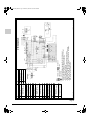
1
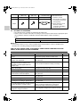
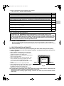
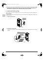
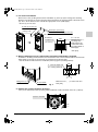
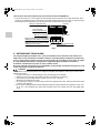
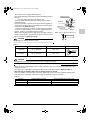
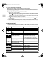
3P249378-4D.book Page 1 Friday, October 28, 2011 2:15 AM
INSTALLATION MANUAL
English
SPLIT SYSTEM
Air Conditioners
Deutsch
MODELS
(Floor standing type)
FVQ71CVEB
FVQ100CVEB
FVQ125CVEB
FVQ140CVEB
Français
Español
Italiano
READ THESE INSTRUCTIONS CAREFULLY BEFORE INSTALLATION.
KEEP THIS MANUAL IN A HANDY PLACE FOR FUTURE REFERENCE.
LESEN SIE DIESE ANWEISUNGEN VOR DER INSTALLATION SORGFÄLTIG DURCH.
BEWAHREN SIE DIESE ANLEITUNG FÜR SPÄTERE BEZUGNAHME GRIFFBEREIT AUF.
LIRE SOIGNEUSEMENT CES INSTRUCTIONS AVANT L’INSTALLATION.
CONSERVER CE MANUEL A PORTEE DE MAIN POUR REFERENCE ULTERIEURE.
LEA CUIDADOSAMENTE ESTAS INSTRUCCIONES ANTES DE INSTALAR.
GUARDE ESTE MANUAL EN UN LUGAR A MANO PARA LEER EN CASO DE TENER
ALGUNA DUDA.
PRIMA DELL’INSTALLAZIONE LEGGERE ATTENTAMENTE QUESTE ISTRUZIONI.
TENERE QUESTO MANUALE A PORTATA DI MANO PER RIFERIMENTI FUTURI.
ΔΙΑΒΑΣΤΕ ΠΡΟΣΕΚΤΙΚΑ ΑΥΤΕΣ ΤΙΣ ΟΔΗΓΙΕΣ ΠΡΙΝ ΑΠΟ ΤΗΝ ΕΓΚΑΤΑΣΤΑΣΗ ΕΧΕΤΕ ΑΥΤΟ
ΤΟ ΕΓΧΕΙΡΙΔΙΟ ΕΥΚΑΙΡΟ ΓΙΑ ΝΑ ΤΟ ΣΥΜΒΟΥΛΕΥΕΣΤΕ ΣΤΟ ΜΕΛΛΟΝ.
LEES DEZE INSTRUCTIES ZORGVULDIG DOOR VOOR INSTALLATIE. BEWAAR DEZE
HANDLEINDING WAAR U HEM KUNT TERUGVINDEN VOOR LATERE NASLAG.
LEIA COM ATENÇÃO ESTAS INSTRUÇÕES ANTES DE REALIZAR A INSTALAÇÃO.
MANTENHA ESTE MANUAL AO SEU ALCANCE PARA FUTURAS CONSULTAS.
ПЕРЕД НАЧАЛОМ МОНТАЖА ВНИМАТЕЛЬНО ОЗНАКОМЬТЕСЬ С ДАННЫМИ
ИНСТРУКЦИЯМИ. СОХРАНИТЕ ДАННОЕ РУКОВОДСТВО В МЕСТЕ, УДОБНОМ ДЛЯ
ОБРАЩЕНИЯ В БУДУЩЕМ.
MONTAJDAN ÖNCE BU TALÝMATLARI DÝKKATLÝ BÝR BÝÇÝMDE OKUYUN.
GELECEKTE BAÞVURMAK ÜZERE BU ELKÝTABINI KOLAY ULAÞABÝLECEÐÝNÝZ BÝR YERDE
MUHAFAZA EDÝN.
Nederlands
Portugues
3P249378-4D_FM6.book Page 1 Thursday, December 15, 2011 10:00 AM
FVQ71CVEB
FVQ100CVEB
FVQ125CVEB
FVQ140CVEB
SPLIT SYSTEM Air Conditioner
Installation manual
CONTENTS
1. SAFETY PRECAUTIONS.....................................................................................1
2. BEFORE INSTALLATION ....................................................................................3
3. SELECTING INSTALLATION SITE......................................................................5
4. INDOOR UNIT INSTALLATION ...........................................................................6
5. REFRIGERANT PIPING WORK...........................................................................8
6. DRAIN PIPING WORK .......................................................................................12
7. WHEN THE OPTIONAL REMOTE CONTROLLER (BRC1E model)
IS USED AS A CONTROL PANEL.....................................................................13
8. ELECTRIC WIRING WORK ...............................................................................17
9. HOW TO CONNECT WIRINGS AND WIRING EXAMPLE ................................18
10. INSTALLATION OF SUCTION GRILLE .............................................................23
11. FIELD SETTING .................................................................................................24
12. TEST OPERATION ............................................................................................25
13. WIRING DIAGRAM.............................................................................................29
This English text is the original instruction. Other languages are translations of the original instructions.
1. SAFETY PRECAUTIONS
Please read these “SAFETY PRECAUTIONS” carefully before installing air conditioning equipment and be
sure to install it correctly.
Meaning of WARNING and CAUTION notices.
Both are important notices for safety. Be sure to follow them.
WARNING ........... Failure to follow these instructions properly may result in personal injury or loss of life.
CAUTION ........... Failure to observe these instructions properly may result in property damage or
personal injury, which may be serious depending on the circumstances.
After completing installation, conduct a test operation to confirm that the equipment operates without any
problems Then, explain to the customer how to operate the equipment and take care of it following the
operation manual. Ask the customer to store the installation manual along with the operation manual for future
reference.
This air conditioner comes under the term “appliances accessible to the general public”.
WARNING
• Ask your dealer or qualified personnel to carry out installation work.
Do not attempt to install the air conditioner yourself. Improper installation may result in water leakage,
electric shocks or fire.
• Install the air conditioner in accordance with the instructions in this installation manual.
Improper installation may result in water leakage, electric shocks or fire.
• When installing the unit in a small room, take measures so that the refrigerant may not exceed the limiting
concentration in the event of refrigerant leakage.
Contact your dealer for further information. If the refrigerant leaks and exceeds the limiting concentration,
it may lead to oxygen deficiency.
English
1
3P249378-4D_FM6.book Page 2 Thursday, December 15, 2011 10:00 AM
• Be sure to use only the specified accessories and parts for installation work.
Failure to use the specified parts may result in the unit falling, water leakage, electric shocks or fire.
• Install the air conditioner on a foundation strong enough to withstand the weight of the unit.
If a foundation does not have sufficient strength, the equipment may fall and cause injury.
• Carry out the required installation work in consideration of strong winds, typhoons or earthquakes.
If the installation work is not properly carried out, the unit may fall down and cause accidents.
• The electrical work must be carried out by the qualified electrician in accordance with the local laws and
regulations and this installation manual. Make sure to provide a dedicated power supply circuit and never
connect additional wiring to the existing circuit.
An insufficient power supply capacity or improper electrical work may lead to electric shocks or fire.
• Be sure to earth the air conditioner.
Do not earth the unit to a utility pipe, lightning conductor or telephone earth lead.
Imperfect earthing may result in electric shocks or fire.
A high surge current from lightning or other sources may cause damage to the air conditioner.
• Be sure to install an earth leakage breaker.
Failure to install an earth leakage breaker may result in electric shocks or fire.
• Be sure to switch off the unit before touching any electrical parts.
Touching a live part may result in electric shock.
• For wiring, use the specified wires and connect and fasten them firmly so that no external force from the
wires may be applied to the terminal connections.
If the wires are not firmly connected and fastened, it may cause heating, fire or the like.
• Wiring for power supply and between the indoor and outdoor units must be properly laid and formed, and
the control box lid must be firmly fastened so that the wiring may not push up the structural parts such as
the lid.
If the lid is improperly fastened, it may cause electric shock or fire.
• If refrigerant gas leaks during installation, ventilate the area immediately.
Toxic gas may be produced if the refrigerant comes into contact with fire.
• After completing installation, check for refrigerant gas leakage.
Toxic gas may be produced if the refrigerant gas leaks into the room and comes into contact with a source
of fire, such as a fan heater, stove or cooker.
• Do not directly touch refrigerant that has leaked from refrigerant pipes or other areas, as there is a danger
of frostbite.
CAUTION
• Carry out drain piping properly following this installation manual and insulate the pipe to prevent
condensation.
Improper drain piping may result in indoor water leakage and property damage.
• Install the indoor and outdoor units, power cord and connecting wires at least 1 meter away from televisions
or radios to prevent picture interference and noise.
(Depending on the incoming signal strength, a distance of 1 meter may not be sufficient to eliminate noise.)
• Install the indoor unit as far as possible from fluorescent lamps.
If a wireless kit is installed in a room where the electronic lighting type (inverter or rapid start types)
fluorescent lamps exist, the transmitting distance of a remote controller may be shorter.
• Do not install the air conditioner in the following locations:
1. Where there is a high concentration of mineral oil spray or vapour (e.g. a kitchen).
Plastic parts may deteriorate and cause parts to fall off or water to leak.
2. Where corrosive gas, such as sulphurous acid gas, is produced.
Corrosion of copper pipes or brazed parts may occur and cause refrigerant leakage.
3. Where there is a machine that generates electromagnetic wave and where voltage fluctuation often
occurs such as a factory.
Control system may malfunction and as a result the unit may not properly operate.
4. Where flammable gas may leak, where carbon fibre or ignitable dust is suspending in the air, or where
volatile flammables such as paint thinner or gasoline are handled.
Operating the unit in such conditions may result in fire.
• The air conditioner is not intended for use in a potentially explosive atmosphere.
2
English
3P249378-4D_FM6.book Page 3 Thursday, December 15, 2011 10:00 AM
2. BEFORE INSTALLATION
Do not exert pressure on the resin parts when opening the unit or when moving it after opening.
Be sure to check in advance that the refrigerant to be used for installation is R410A. (If a wrong
refrigerant is charged, the unit will not properly operate)
• For the installation of an outdoor unit, refer to the installation manual attached to the outdoor unit.
• Do not dispose of any parts necessary for installation until the installation is completed.
• Decide the route for carrying the unit to the installation site.
• When hanging the unit for lifting, use a sling of soft material (made of cloth, nylon, etc.) as shown below. (Refer to Fig. 1)
(1) Horizontal hanging
(2) Vertical hanging
Sling
Sling
Apply cloth or corrugated
cardboard so that the air
discharge grille and air inlet
grille will not be damaged.
*Be sure that the sling
does not slide.
Fig. 1
2-1 PRECAUTIONS
• When selecting installation site, refer to the paper pattern (part of packaging material).
• Do not use the unit in locations where the salt content in the air is high such as beachfront, or where the
voltage fluctuates such as factories, or where the base vibrates such as automobiles or marine vessels.
• Before opening the control box lid and performing the wiring operation, remove the static electricity charged
to your body. Otherwise, electrical parts may be damaged.
2-2 ACCESSORIES
Check the following accessories are included with the unit.
Do not dispose of any parts necessary for installation until the installation is completed.
Name
(1) Bracket for installation
Quantity
1 set
*1)
(3) Hole protection
rubber
2 pcs.
(4) Bush
1 pc.
Insulation for fitting
1 each
(5) For gas pipe
Shape
(2) Screw (M4 × 10), 1 pc.
Name
Quantity
(7) Cover
1 pc. *2)
(6) For liquid pipe
(8) Clamp
(9) Installation pattern
5 pcs.
1 pc.
(10) Dew proof
material
1 pc.
Also used as a
packaging material
Shape
English
3
3P249378-4D_FM6.book Page 4 Thursday, December 15, 2011 10:00 AM
Name
Quantity
(11) Screws
(M4 × 10)
3 pcs. *2)
(12) Screws
(M5 × 12)
2 pcs.
(13) Remote
controller wiring
1 pc.
*2)
(Other)
• Operation manual
• Installation manual
*1) The bracket for installation
is screwed onto the main
unit (top plate).
Shape
*2) These parts are used
when the remote
controller is installed in
the main unit.
2-3 OPTIONAL ACCESSORIES
• The optional remote controller is required for this indoor unit.
• Select a remote controller from Table 1 according to customer request and install in an appropriate place.
(For installation, follow the installation manual included with the remote controllers.)
Table 1
Wired type
Remote controller
BRC1E52A7/BRC1E51A7/BRC1D528
NOTE
• If the customer wishes to use a remote controller that is not listed above, select a suitable remote
controller after consulting catalogs and technical guide.
FOR THE FOLLOWING ITEMS, TAKE SPECIAL CARE DURING CONSTRUCTION AND
CHECK AFTER INSTALLATION IS FINISHED.
1. Items to be checked after completion of work
Items to be checked
Are the indoor unit and outdoor unit fixed
firmly?
Is the installation of the indoor unit and the
outdoor unit completed?
Is the gas leakage checked with the
leakage test pressure written in the
installation manual supplied with the
outdoor unit?
Is the unit fully insulated? (Refrigerant
piping, drain piping)
Does drainage flow smoothly?
Does the power supply voltage correspond
to that shown on the name plate?
Are wiring and piping correct?
Is the unit safely grounded?
Is wiring size according to specifications?
Is something blocking the air outlet or inlet
of either the indoor or outdoor units?
Are refrigerant piping length and additional
refrigerant charge noted down?
4
If not properly done, what is likely to occur
Check
The unit may drop, vibrate or make noise.
The unit may malfunction or the components
may burn out.
It may result in insufficient cooling or heating.
Condensate water may drip.
Condensate water may drip.
The unit may malfunction or the components
may burn out.
The unit may malfunction or the components
may burn out.
It may result in electric shock.
The unit may malfunction or the components
may burn out.
It may result in insufficient cooling or heating.
(This can lead to malfunction or decreased
performance due to decreased air volume.)
The refrigerant charge in the system is not clear.
English
3P249378-4D_FM6.book Page 5 Thursday, December 15, 2011 10:00 AM
2. Items to be checked at time of delivery to customer.
* Also review the ‘‘1. SAFETY PRECAUTIONS’’
Items to be checked
Has the field setting done (as necessary)?
Did you attach the control box lid, the air filter, and suction grille?
Does the cold air (warm air) blow properly during the cooling (heating) operation?
Did you explain about operations while showing the operation manual to your customer?
Did you explain the cooling, heating, dry, and automatic cooling/heating operations described
in the operation manual?
Did you explain what the set airflow rate is when setting the airflow rate at thermostat off to the
customer?
Is the emergency switch (EMG.) of the printed circuit board turned ON? At delivery from the
factory, it is set to normal (NORM).
Is the suction thermistor installed at its original position (bell mouth) when the optional adapter
installation box is installed?
Did you hand the operation manual over to your customer? (Please hand over the installation
manual as well.)
Check
Points for explanation about operations
Since the items with
WARNING and
CAUTION marks in the operation manual, if not
observed, may cause injuries and/or material damages. Therefore, in addition to the general usage,
it is necessary to explain them to the customer and also to ask the customers to thoroughly read
them. Accordingly, it is necessary that you make a full explanation about the described contents
and also ask your customers to read the operation manual.
2-4 NOTE TO THE INSTALLER
Be sure to instruct customers how to properly operate (especially cleaning filters, operating different
functions, and adjusting the temperature) by having them carry out operations by themselves while reading
the manual literally.
3. SELECTING INSTALLATION SITE
Do not exert pressure on the resin parts when opening the unit or when moving it after opening.
(1) Select an installation site where the following conditions are fulfilled and that meets with your customer’s approval.
• Where optimum air distribution can be ensured.
• Where the floor is strong enough to withstand the
weight and vibration of the indoor unit.
• Make sure the floor is level. (Vibration and abnormal
noise may be generated.)
• Where nothing blocks the air inlet and outlet, and
where sufficient clearance for maintenance and
Main unit
service can be ensured. (Refer to Fig.2)
(If not ensured, the capacity may drop due to short
circuit.)
50mm
50mm
• Where condensate can be properly drained.
or more
or more
• Where piping between indoor and outdoor units is
possible within the allowable limit. (Refer to the
Fig. 2
installation manual for the outdoor unit.)
• Where there is no risk of flammable gas leakage.
(2) Install the indoor and outdoor units, power cord and connecting wires at least 1 meter away from
televisions or radios to prevent picture interference and noise.
(Depending on the incoming signal strength, a distance of 1 meter may not be sufficient to eliminate noise.)
English
5
3P249378-4D_FM6.book Page 6 Thursday, December 15, 2011 10:00 AM
(3) Investigate whether the installation location (such as the floor and wall) can withstand the weight
of the unit and, if necessary, reinforce the location with such as beams before installation. To
avoid vibration and abnormal noise, reinforce the location before installation.
4. INDOOR UNIT INSTALLATION
As for the parts to be used for installation, be sure to use the attached accessories and the specified parts.
〈Fixing procedure〉
• Since the indoor unit is vertically tall, take measures to prevent the unit from falling down according to the
following method.
1. Raise the grille fixture.
Grille fixture
Fig. 3
2. Detach the suction grille.
Remove the screws (R & L, total 2) locking the grille stopper. Then, (1) tilt the grille forward, and (2) lift
upward.
M4 × 12
Tapping screws (class 2)
Front panel (2)
(1)
Grille fixture
Grille stopper
Suction grille
Fig. 4
6
English
3P249378-4D_FM6.book Page 7 Thursday, December 15, 2011 10:00 AM
3. For normal installation.
Remove the screw (2) fixing the bracket for installation (1) to the top panel. Change the mounting
direction of the bracket as shown in the figure below and fix it to the top panel with the attached screws
(12). Then, fix the bracket to the wall with the appropriate screws (field supply).
• Screws (2) are not used.
Screw (2) (accessory)
not necessary
Screw (12) (accessory)
Fixing screw
Bracket for installation (1) (accessory)
Bracket for
installation (1)
(accessory)
18
330
Fig. 5
2-7 × 15 slot
(Screw hole for
securing to the
wall) Prepare the
screws that match
the wall material as
field supply.
• Unit [mm]
4. When installing the unit to a place where strength to earthquake is required.
In addition to the fixing method shown left, fix the bottom frame to the foundation with the anchor bolts
(field supply). Four holes for anchor bolts are prepared on the bottom plate.
• Use the locations indicated on the installation pattern (9) (part of packing material).
57
(79)
(202)
130
(For locking with bolt)
144
260
4 - φ14 hole, Depth: 30
Front
• Dimensions in (
Fixing holes (× 4)
Bottom frame
) for 100 - 140 class
• Unit [mm]
Fig. 6
5. Remove the cushion materials of the fan.
It may cause malfunction when operating while installed the cushion materials of the fan. (4 places)
Cushion materials
Fan
Fig. 7
English
7
3P249378-4D_FM6.book Page 8 Thursday, December 15, 2011 10:00 AM
〈How to attach dew proof material (only when connected with the RZQSG71L)〉
• To make the work easy, set the upper 5 horizontal flaps upward and the lower 3 flaps downward. Then,
attach the provided dew proof material (10) to the third horizontal flap from the bottom as shown in Fig.8.
If the material is not attached to the correct place, dew condensation water may drip.
Upward
Dew proof material (10)
(accessory)
Horizontal flap
(3rd from the bottom)
Dew proof material
Downward
Attach the dew proof material while
aligning it to the dew proof material.
Attach the dew proof material while
aligning it to the centre.
Dew proof material (10)
(accessory)
Fig. 8
5. REFRIGERANT PIPING WORK
〈For refrigerant piping of outdoor units, see the installation manual attached to the outdoor unit.〉
〈Make sure to carry out thermal insulation in both gas and liquid piping. Incomplete insulation may
result in water leakage. Thermal resistance of the insulation for gas piping must be 120°C or higher.
In a high humidity environment, strengthen the refrigerant piping insulation. If insulation is
insufficient, condensation may form on the insulation surface.
Be sure to check that the refrigerant is R410A before starting the job. (If a different refrigerant is used,
a normal operation cannot be carried out.)〉
CAUTION
This product is a dedicated model for new refrigerant (R410A). At installation, make sure to observe the
following precaution.
• For flare connection, use dedicated pipe cutter and flaring tools for R410A.
• Apply ester oil or ether oil to the inside of the flare section before connecting.
• Use the flare nuts provided with the unit. Do not use a class 1 flare nut.
Otherwise the refrigerant may leak.
• To prevent dust, moisture or other foreign matters from getting into the tube, either pinch the tube end or
cover the end with tape.
• Do not allow anything other than the designated refrigerant to get mixed into the refrigerant circuit, such
as air, etc. If any refrigerant gas leaks while working on the unit, ventilate the room thoroughly right
away.
8
English
3P249378-4D_FM6.book Page 9 Thursday, December 15, 2011 10:00 AM
• The outdoor unit is charged with refrigerant.
• The refrigerant piping can be taken out from the following side of
the unit.
Left side, Right side, Back side, Bottom side
You must decide from which side you intend to take out the
refrigerant piping.
• Be sure to use both a spanner and a torque wrench together as
shown in the drawing, when connecting or disconnecting pipes
to/from the unit. (Refer to Fig. 9)
* Using a tool other than a spanner can damage the head of the
flare nut, and gas leakage can occur due to tightening failure.
• Refer to “Table 2” for the dimensions for flaring.
• When connecting the flare nut, apply ester oil or ether oil to the
inside of flared section, and turn the nut spin 3-4 times by hand
before screwing in. (Refer to Fig. 10)
Torque wrench
Spanner
Pipe union
Flare nut
Fig. 9
Apply ester or ether oil to this face.
CAUTION
Be careful not to damage the flare section.
Fig. 10
Table 2
32.7 - 39.9 N·m
12.8 - 13.2
φ15.9 (5/8”)
61.8 - 75.4 N·m
19.3 - 19.7
˚
φ9.5 (3/8”)
Flare
R0.4-0.8
45˚2
Flare dimensions A (mm)
A
Tightening torque
90˚ 2˚
Pipe size
• Refer to “Table 2” to determine the proper tightening torque.
CAUTION
Overtightening may damage the flare and cause a refrigerant leakage.
When you do not have a torque wrench, use Table 2 as a rule of thumb.
When you keep on tightening the flare nut with a spanner, there is a point where the tightening torque
suddenly increases.
From that point, further tighten and turn the flare nut the angle shown below. (Refer to Table 3)
After the work is finished, make sure to check that there is no leak.
Unless you tighten as instructed, (if it is loosely tightened), it may lead to the refrigerant leakage (slow
leak) and cause malfunction of the device (such as insufficient cooling or heating).
Table 3
Pipe size
φ9.5 (3/8”)
φ15.9 (5/8”)
English
Further tightening angle
60 to 90 degrees
30 to 60 degrees
Recommended arm length of tool
Approx. 200mm
Approx. 300mm
9
3P249378-4D_FM6.book Page 10 Thursday, December 15, 2011 10:00 AM
1. How to carry out refrigerant piping.
• Detach the pipe retainer. (Refer to Fig. 12)
〈 In case of left or right piping 〉
1. Open the knock out holes on the right (left) side panel. (Refer to Fig. 11)
2. Carry out piping (refrigerant and drain) and wiring (connecting outdoor and indoor units) through the
holes on the side panel.
(See dimensions shown in Fig. 15 for forming refrigerant piping.)
Knock out holes for piping (Select either one)
(left and right side panels and rear panel)
* Put the attached hole protection rubber (3) (
after making the opening.
Bottom frame
)
Through holes for wiring (Select either one)
(left and right side panels)
* Put the attached bush (4) (
) after making the opening.
Side panel
Fig. 11
〈 In case of rear piping 〉
1. Open the knock out holes on the rear panel. (Refer to Fig. 14)
2. Carry out piping (refrigerant and drain) and wiring (connecting outdoor and indoor units) through the
holes on the rear panel.
(See dimensions shown in Fig. 15 for forming refrigerant piping.)
CAUTION
In case of rear side piping, be careful not to damage fan motor lead wire.
When opening the knock out hole, be careful not to damage fan motor lead wire with the steel plate cut
off. (Refer to Fig. 16).
〈 In case of downward piping 〉
1. Cut holes in the indicated area of the bottom frame. (Refer to Fig. 14)
2. Carry out piping (refrigerant and drain) and wiring (connecting outdoor and indoor units) through the
holes on the bottom frame.
CAUTION
Be careful not to damage fan housing when piping.
Fan housing is made of foamed polystyrene.
Be careful not to damage the fan housing with pipe edge when installing indoor unit.
10
English
3P249378-4D_FM6.book Page 11 Thursday, December 15, 2011 10:00 AM
Fan motor
lead wire
Insulation for fitting (5)(6)
(accessory)
Fix using the
clamp (8)
• Unit [mm]
Fig. 13
Pipe retainer
525
450
Backward piping
450
525
Right or left piping
Fig. 15
Fig. 12
Fan motor
lead wire
Fan housing
Drain hose
inside the unit
Rear panel
Knock out holes
(Select either one)
Rear plate
* Put the
attached hole
protection
rubber (3)
(
)
after making
the opening.
Knock out holes
Bottom frame
Fig. 16
Cut holes here.
Fig. 14
• After the refrigerant piping and electrical wiring work is completed, hold the refrigerant piping, the
indoor unit drain hose, the wiring connecting the indoor and outdoor units and the earth wire with the
piping retainer plate (Refer to Fig. 12). During this work the refrigerant piping entering into the indoor
unit may come in contact with the suction grille. Therefore, make sure not to extend the refrigerant
piping from the piping retainer plate.
(For electrical wiring work, see “8. ELECTRIC WIRING WORK”.)
• After leakage check of piping connection is finished, carry out thermal insulation. (Refer to Fig. 13)
• Carry out thermal insulation of both liquid and gas pipes with the attached insulation for fitting (5) and
(6). (Tighten both ends of the insulation for fitting (5) and (6) with the clamp (8).
CAUTION
Be sure to insulate any field piping all the way to the piping connection inside the unit.
Any exposed piping may cause condensation or burns if touched, and also electrical shock or fire if the
wiring is touched.
CAUTION
• CAUTION TO BE TAKEN WHEN BRAZING REFRIGERANT PIPING
• Do not braze inside the unit.
Since the bottom plate and the fan housing are made of resin. They may melt or cause fire by spatter.
English
11
3P249378-4D_FM6.book Page 12 Thursday, December 15, 2011 10:00 AM
• Braze the refrigerant piping only after having nitrogen flow through the pipe and substituting nitrogen for air
(Refer to Fig. 17). Once this is completed, connect the indoor unit with flares (Refer to Fig. 13).
1. When brazing after having nitrogen flow through the pipe and substituting nitrogen for air, it is appropriate
to set the nitrogen pressure to about 0.02MPa with a pressure reducing valve. (Refer to Fig. 17)
2. Do not use flux when brazing refrigerant piping. Use the phosphor copper brazing filler metal (BCuP-2: JIS
Z 3264/B-Cu93P-710/795: ISO 3677) that does not require flux.
(Chlorine based flux is extremely harmful to refrigerant piping systems. It will corrode the refrigerant piping
and if it contains fluorine it will deteriorate the refrigerating oil.)
3. When performing the leakage test for the indoor unit and inter-unit piping after the indoor unit is installed,
be sure to refer to the installation manual for the indoor unit or technical guide for the leakage test pressure
and the refrigerant piping installation.
4. Shortage of refrigerant due to air purge or forgetting the additional refrigerant charge may cause
malfunction of the unit (does not sufficiently cool or heat).
For installation of refrigerant piping, be sure to refer to the installation manual for the outdoor unit or the
technical guide.
Refrigerant piping
Part to be
brazed
Taping
Nitrogen
Fig. 17
Hands
valve
Pressure-reducing
valve
Nitrogen
CAUTION
• Do not use anything oxidation inhibitor or the like when brazing. (Residues may cause clogging of pipes or
damage to parts.)
6. DRAIN PIPING WORK
1. Rig the drain piping.
Carry out drain piping to ensure proper drainage. Also, observe the following to prevent leaks.
Indoor unit drain hose
Fan housing
Through-hole for piping
Liquid pipe
Gas pipe
Bottom frame
Anchor hose here.
Drain pipe (Procure in field.)
Fig. 18
Vinyl chloride pipe (normal diameter 20mm)
CAUTION
• To avoid force on the drain hose of the indoor unit, make sure to fix the drain pipe such as to bundle it to the
refrigerant pipe as shown in Fig. 18. This is to prevent the drain pipe from coming off and/or avoid bad
insulation. The drain pipe must be sloped downward with a gradient of 1/100 from the drain pipe connection in
the unit.
• The drain pipe may be clogged if water accumulates in the drain pipe.
• Condensation on the pipe may occur and cause water leakage. Therefore, make sure to insulate the pipe
at the following two places.
(1) All piping in the room and inside the unit.
12
English
3P249378-4D_FM6.book Page 13 Thursday, December 15, 2011 10:00 AM
(2) At the connection between the indoor unit drain hose and the field drain piping.
2. After the piping work is finished, check that drainage flows smoothly and the water
does not leak from connections.
• Carefully pour approximately 1
litre of water through the air
discharge outlet so that it falls
directly onto the heat
exchanger at an angle without
splashing. (Refer to Fig. 19)
* If water is poured too fast or if
water pressure is too high, the
water will pass through the
heat exchanger and drip on
the fan motor below it.
* If water gets on the inner front
wall, it will leak onto the floor.
Air discharge
outlet
Heat
exchanger
Fig. 19
CAUTION
• In order to prevent the pets from getting inside the unit, seal the pipe penetration hole with putty or heat
insulating material (field supply).
• Drain piping connections
Do not connect the drain piping directly to sewage pipes that smell of ammonia. The ammonia in the
sewage might enter the indoor unit through the drain pipes and corrode the heat exchanger.
7. WHEN THE OPTIONAL REMOTE CONTROLLER (BRC1E model) IS USED
AS A CONTROL PANEL
(Remote controllers except the optional BRC1E cannot be incorporated
into the main unit.)
• The optional remote controller (BRC1E) can be incorporated into this unit and used as a control panel.
1. Open the remote controller, and connect the remote controller wiring (accessory).
For wiring procedures, refer to the “remote controller installation manual”.
(There is no polarity for the remote controller wiring.)
1) Remove the upper case.
Insert a flathead screwdriver into the concaved portion of the lower case (at 2 positions), and then
remove the upper case.
Upper case
Screwdriver
Lower case
Fig. 20
Insert the screwdriver and twist it lightly to
remove the case.
CAUTION
• The printed circuit board of the remote controller is attached to the upper case. Be careful not to scratch the
board with the screwdriver.
English
13
3P249378-4D_FM6.book Page 14 Thursday, December 15, 2011 10:00 AM
• Be careful not to adhere any dust or liquid to the printed circuit board of the removed upper case.
2) Cut off the shaded part of the lower case, and then fix the case to the cover (7) using screws (11).
Shaded part
Screw (11) (M4)
(Tightening torque : 0.6 ± 0.1N · m)
(accessory)
Lower case
Cover (7)
(accessory)
Lower case assy
Fig. 21
3) Connect the remote controller wiring (accessory (13)).
Remote controller
wiring (13)
Clamp
(accessory of the
remote controller)
Fixed part
Upper case
assy
A
Fixed part
A
Upper case
assy
Section A-A
Clamp
(accessory of the remote controller)
Remote controller
wiring (13)
(accessory)
Lower case assy
Fig. 22
14
English
3P249378-4D_FM6.book Page 15 Thursday, December 15, 2011 10:00 AM
4) Fit and install the upper case in the lower case while aligning the tabs (6 positions) with the lower
case.
• Be careful so that the wiring may not be caught.
• Remove the protection sheet attached to the upper case.
Upper case assy
Remote controller
wiring (13)
(accessory)
Hole
Lower case assy
〈Control panel〉
Tabs (6 positions)
Fig. 23
2. Remove the front panel, and then remove the back plate attached to the back side.
• When removing the front panel, to avoid dropping the panel, tightly hold the front panel while
removing it.
Front panel
Wire harness for the
swing motor
Screw (M4)
Screw
(M4)
Terminal block (X1M: 4P)
Screw (M4)
Control box lid
Screw (M4)
Front panel
Back plate
Screw (M4)
(6 pcs.)
English
Fig. 24
15
3P249378-4D_FM6.book Page 16 Thursday, December 15, 2011 10:00 AM
NOTE
• If the grille fixture comes off while
removing the front panel, attach the grille
fixture as shown below.
1. Install the grille fixture while aligning its
notch with the rib of the front panel.
2. Lower the grille fixture.
Grille fixture
Rib
Rib
Front panel
1.
2.
Notch
Fig. 25
3. Fix the control panel on the back side of the front panel.
Front panel
Control panel
Screw (M4)
(6 pcs.)
Fig. 26
4. Clip the remote controller wiring into the guide and notch. (Refer to Fig. 27)
Control panel
Front panel
Remote controller wiring (13)
(accessory)
Be sure not to leave
any slack in the remote
controller wiring
between these parts.
Guide
Notch
Be sure not to leave any slack in the remote
controller wiring between these parts.
Fig. 27
16
English
3P249378-4D_FM6.book Page 17 Thursday, December 15, 2011 10:00 AM
5. Return the front panel to its original installation position.
6. Remove the control box lid, and then connect the remote controller wiring to terminals
P1 and P2 (no polarity) of the terminal block (X1M).
Terminal block (X1M : 4P)
High voltage wires and
earth wire
Low voltage wires
P2
P1
Remote controller
wiring (13)
(accessory)
Fig. 28
8. ELECTRIC WIRING WORK
8-1 GENERAL INSTRUCTIONS
• Electric wiring work must be conducted by an electrician authorized by power companies (Only a licensed
electrician is permitted to conduct electric work and earth connections.)
• All wiring must be performed by an authorized electrician.
• A circuit breaker capable of shutting down power supply to the entire system must be installed.
• Be sure to install an earth leakage circuit breaker in the outdoor unit.
(Install the earth leakage circuit breaker to avoid electric shocks and fire.)
• The specified voltage for the wiring between the indoor and outdoor units and between the indoor units is
220-240V.
• Do not turn on the power supply (of the indoor unit) until all the installation work is completed.
• Be sure to earth the air conditioner.
• Refer to the installation manual attached to the outdoor unit for the size of power supply electric wire
connected to the outdoor unit, the capacity of the circuit breaker and switch, and wiring instructions.
• Do not connect the earth wire to gas pipes, plumbing pipes, lightning rods, or telephone earth wires.
• Gas pipes: might cause explosions or fire if gas leaks.
• Plumbing: no earth effect if hard vinyl piping is used.
• Telephone earth wires or lightning rods: might cause abnormally high electric potential in the earth
during lighting storms.
• For electric wiring work, refer also to “WIRING DIAGRAM” attached to the back side of the control box lid.
• Never connect the power supply wire to the terminal block for remote controller wire, or otherwise the entire
system may be damaged.
• For remote controller wiring details, refer to the installation manual attached to the remote controller.
• Do not touch the printed circuit board assy during the wiring work. Otherwise, it may cause damage.
English
17
3P249378-4D_FM6.book Page 18 Thursday, December 15, 2011 10:00 AM
8-2 SPECIFICATIONS FOR FIELD WIRE
For the wiring of the outdoor unit, refer to the installation manual attached to the outdoor unit.
Remote controller and transmission wiring are field supplied. (Refer to Table 4)
Wiring specifications are shown on the condition that the wiring has a voltage drop of 2%.
Table 4
2
Wire
Wiring the units
Remote controller cord
H05VV-U4G
(NOTE 1)
Vinyl cord with sheath or
cable (2 wire) (NOTE 2)
Size (mm )
Length
2.5
–
0.75 - 1.25
Max. 500m *
*This will be the total extended length in the system when doing group control.
NOTE
1. It shows the case when conduit pipes are used. When the conduit pipes are not used, use H07RN-F.
2. Sheathed vinyl cord or cable (insulation thickness: 1mm or more)
9. HOW TO CONNECT WIRINGS AND WIRING EXAMPLE
9-1 HOW TO CONNECT WIRINGS
Earth terminal
Clamp (8)
(accessory)
Power supply
terminal block
(X2M:3P)
Wiring the units
Inter unit wire for the indoor and
outdoor units and earth wire
Earth wire
Fig. 30
Pipe retainer
Wiring
diagram
Control box lid
Earth terminal
Outdoor unit
Indoor unit
1
2
3
1
2
3
(Terminal block)
(Terminal block)
Wiring lead-in port
1 2 3
Fig. 29
Align the numbers.
How to connect the inter unit wiring for
the indoor and outdoor units
• Do not perform solder finishing.
18
English
3P249378-4D_FM6.book Page 19 Thursday, December 15, 2011 10:00 AM
〈 Connecting methods of wiring between indoor and outdoor units, earth wiring, and remote
controller wiring 〉
• Detach the control box lid and pipe retainer as shown in the Fig. 29 and connect the wires of matching
numbers to the terminal block (X2M: 3P) on the right side of the unit. Connect the earth wire to the earth
terminal. In doing this, draw the wiring into the unit through the hole for wiring, and fix it together with the
earth wire using the clamp (8).
• Connect the remote controller wiring (field supply) to the terminals P1 and P2 (no polarity) of the terminal
block (X1M: 4P), and guide the wiring to the outside of the unit using the route shown in the Fig. 31.
• Pass the remote controller wiring inside the piping retainer plate.
• Route the low voltage wires (remote controller wiring) 50mm or more away from the high voltage wires
(interconnecting wires between the indoor and outdoor units) and earth wire so that they may not pass
through the same place. (Refer to Fig. 31)
Terminal block
(X1M : 4P)
Terminal block
(X2M : 3P)
High voltage wires
and earth wire
P2
P1
Low voltage wires
Route the low voltage wires through the right side of the
piping to the upper hole on the right (left) side plate.
Fig. 31
Route the high voltage wires and earth wire through the left
side of the piping to the lower hole on the right (left) side
plate while installing the provided bushing (4).
• During the wiring work, lay the electric wiring neatly so that the wires may not push the control box lid up.
Also, fix the lid without sandwiching the wires between the box and the lid.
(Sandwiching electric wires and/or having the lid float up may result in electric shock or fire.)
• Pass the interconnecting wires and the earth wires inside of the pipe pressing plate. Wires connecting the
units and the earth wire to the pipe retainer. Keep the extra wires neatly at a location shown in the Fig. 30.
The wires may come in contact with other parts such as the fan, and the indoor unit may be damaged.
• In order to prevent small creatures getting into the unit, seal the wiring outlet with putty or heat insulating
material (field supply) leaving no clearance. (If small creatures, such as insects, get into the unit, the
creatures may cause short circuiting in the control box.)
CAUTION
Use a round crimp-style terminal for connection to the power supply terminal block. (Refer to Fig. 32)
In case it cannot be used due to unavoidable reasons, be sure to observe the following instructions.
• Do not connect wires of different gauge to the same power supply terminal.
(Looseness in the connection may cause overheating.) (Refer to Fig. 33)
• In wiring, make certain that prescribed wires are used. Also, fix the wires so that external force may not
be applied to the terminals.
• Use an appropriate screwdriver to tighten the terminal screws. Small screwdrivers damage the head of
the screws and they cannot tighten the screws appropriately.
English
19
3P249378-4D_FM6.book Page 20 Thursday, December 15, 2011 10:00 AM
• If the terminal screws are tightened too hard, screws Table 5
might be damaged.
Tightening torque (N·m)
• The tightening torque of each terminal screw is shown
Terminal block for remote controller wiring
in the Table 5.
Terminal block for wiring between units
• When a stranded wire is used, do not perform solder
Earth terminal
finishing.
Round crimp-style
terminal
Connect wires of the
same gauge to both
side. (GOOD)
0.79~0.97
1.18~1.44
1.18~1.44
Do not connect wires
of the same gauge to
one side. (WRONG)
Do not connect wires
of different gauges.
(WRONG)
WRONG
WRONG
Electric wire
Fig. 32
GOOD
Fig. 33
9-2 WIRING EXAMPLE
CAUTION
Be sure to install an earth leakage breaker to the outdoor unit.
This is to avoid electric shocks or fire.
For the wiring of outdoor units, refer to the installation manual attached to the outdoor units.
Confirm the system type.
• Pair type: 1 remote controller controls 1 indoor unit (standard system). (Refer to Fig. 34)
• Group control: 1 remote controller controls up to 16 indoor units
(All indoor units operate according to the remote controller). (Refer to Fig. 35)
• 2 remote controllers control: 2 remote controllers control 1 indoor unit. (Refer to Fig. 37)
Pair type
Main power supply
Earth leakage
circuit breaker
1 2 3
Outdoor unit
1 2 3
P1 P2
Indoor unit
P1 P2
Remote controller
(Optional accessory)
20
Fig. 34
English
3P249378-4D_FM6.book Page 21 Thursday, December 15, 2011 10:00 AM
Group control
Main power supply
Earth
leakage
circuit
breaker
Earth
leakage
circuit
breaker
1 2 3
Earth
leakage
circuit
breaker
1 2 3
Outdoor unit
1 2 3
1 2 3
Outdoor unit
1 2 3
P 1 P2
1 2 3
P1 P2
Indoor unit
Indoor unit
(Master)
P1 P 2
Outdoor unit
P1 P2
Indoor unit
Group control remote controller
(Optional accessory)
Fig. 35
When implementing group control
• When using as a pair unit, you may carry out simultaneous start/stop (group) control up to 16 units with the
remote controller. (Refer to Fig. 36)
• In this case, all the indoor units in the group will operate in accordance with the group control remote controller.
• The body thermo is effective only for the indoor unit to which the remote controller is connected.
Outdoor unit 2
Outdoor unit 1
Indoor
unit 1
Indoor
unit 2
Outdoor unit 16
Indoor
unit 16
Group control remote controller
Fig. 36
Wiring Method
(1) Remove the control box lid. (Refer to ‘‘9. HOW TO CONNECT WIRINGS AND WIRING EXAMPLE’’.)
(2) Lay crossover between the terminals (P1, P2) inside the control box for the remote controller. (There is no
polarity.) (Refer to Fig. 35 and Table 4)
English
21
3P249378-4D_FM6.book Page 22 Thursday, December 15, 2011 10:00 AM
2 remote controllers control
Main power supply
Earth leakage
circuit breaker
1 2 3
Outdoor unit
Outdoor unit
Indoor unit
1 2 3
P1 P2
Indoor unit
Remote
controller P P
(Optional
accessories)
1
2
P1 P 2
Remote
controller
(Optional
accessories)
Remote
Remote
controller 1 controller 2
Fig. 37
Two remote controllers control (Controlling 1 indoor unit by 2 remote controllers)
• When using 2 remote controllers, one must be set to “MAIN” and the other to “SUB”.
MAIN/SUB CHANGEOVER
• If BRC1E type remote controller is used, see the manual attached to the remote controller.
If the remote controller is a wired one, change the switch setting as follows:
(1) Insert a flat screwdriver into the clearance between the upper case and the concave of the lower case and,
remove the upper case. (2 places) (Printed circuit board is attached to the upper part of the remote controller.) (Refer to Fig. 38)
(2) Turn the main/sub changeover switch on one of the two remote controller printed circuit boards to “S”.
(Leave the switch of the other remote controller set to “M”.) (Refer to Fig. 39)
Fig. 38
Upper case of
remote controller
Fig. 39
(Factory setting)
Insert the screwdriver
here and gently work
off the upper part of
remote controller.
Lower case of
remote controller
(Only one remote
controller needs
to be changed if
factory settings
have remained
untouched.)
S
M
S
M
Remote
controller printed
circuit board
Wiring Method
(3) Remove the control box lid (Refer to ‘‘9. HOW TO CONNECT WIRINGS AND WIRING EXAMPLE’’.)
(4) Add wiring between the remote controller 2 (slave) and the terminal (P1, P2) of the terminal block
(X1M) for the remote controller in the control box. (There is no polarity.) (Refer to Fig. 37 and Table
4)
NOTE
1. All transmission wiring except for the remote controller wires is polarized and must match the terminal symbol.
2. For group control remote controller, choose the remote controller that suits the indoor unit which has the
most functions (as attached swing flap).
22
English
3P249378-4D_FM6.book Page 23 Thursday, December 15, 2011 10:00 AM
10. INSTALLATION OF SUCTION GRILLE
1. Hook the suction grille on the groove on the unit’s bottom frame in the order of (1) →
(2). (Refer to Fig. 40)
(2)
(1)
(2)
(1)
Suction
grille
Bottom frame
Suction grille
Bottom frame
Fig. 40
2. Fit the grille stopper (front panel) into the groove on the suction grille and lock the
grille down in its original place by screw. (Refer to Fig. 41)
* Be careful not to overtighten screws.
3. Check that the grille fixture is raised, and then close the suction grille. After closing the
grille, lower the grille fixture. (Refer to Fig. 41)
M4 × 12
Screw
Front panel
Grille
fixture
Grille stopper
Suction grille
Suction grille
Bottom frame
Fig. 41
English
23
3P249378-4D_FM6.book Page 24 Thursday, December 15, 2011 10:00 AM
11. FIELD SETTING
〈 Complete all the “1. Items to be checked after completion of work” on page 4. 〉
• Make sure that the installation and wiring work for the indoor and outdoor units is all completed.
• Make sure that the following items are all closed: the control box lid of the indoor unit and the outer board
and piping cover of the outdoor unit.
<Field setting must be made from the remote controller and in accordance with installation conditions.>
• Setting can be made by changing the “Mode No.”, “FIRST CODE NO.” and “SECOND CODE NO.”.
• For setting procedures and instructions, see the manual provided with the remote controller.
NOTE
• The “Mode No.” is normally set collectively for a group. In order to set each indoor unit individually and perform checks after the settings, specify the Mode No. in parenthesis.
• Do not perform settings that are not listed in the table.
11-1 SETTING AIR FILTER SIGN
• The filter sign that notifies you of the necessity for air filter cleaning is displayed on the LCD display
of the remote controller.
• Change the SECOND CODE NO. below depending on the amount of dirt or dust in the room.
(As the factory setting, the FIRST CODE NO. 1 is set to the SECOND CODE NO. “01” for the long
time, and the FIRST CODE NO. 0 is set to the SECOND CODE NO. “01”, air filter contamination light.) (Refer to Table 6)
Explain to the customer that filters need to be cleaned periodically to prevent clogging, and the time
that is set.
• The periodical cleaning time for the filter can be shortened depending on the usage environment.
Table 6
Setting
Mode No.
Cleaning time
Air Filter
contamination:
light/heavy
SECOND CODE NO.
01
02
04
For long
For short
—
time
time
Approx.
Approx.
—
2,500 hours 1,250 hours
Approx.
Approx.
—
200 hours
100 hours
FIRST
CODE NO.
1
For long time
10 (20)
0
For short time
are the settings when shipped from the factory.
11-2 AIRFLOW SETTINGS WHEN THERMOSTAT IS OFF
• Set the flow rate according to the requirement of the environment after consultation with the customer.
(Refer to Table 7)
• When the airflow is changed, explain the airflow rate setting to the customer.
Table 7
Setting
Fan operation when thermostat
is OFF (Cooling/Heating)
Airflow rate when cooling
thermostat is OFF
Airflow rate when heating
thermostat is OFF
24
Normal
Stop
LL airflow rate
Setting airflow rate
LL airflow rate
Setting airflow rate
Mode No.
FIRST
CODE NO.
11 (21)
2
12 (22)
6
12 (22)
3
SECOND
CODE NO.
01
02
01
02
01
02
English
3P249378-4D_FM6.book Page 25 Thursday, December 15, 2011 10:00 AM
11-3 SETTING AIRFLOW RATE INCREASE MODE (71 · 100 class)
• The set airflow rate (HH, H, and L) can be increased depending on the installation condition or
customer’s request. In such a case, switch the SECOND CODE NO. as shown in Table 8.
Table 8
Setting
Standard
Slightly increase
Increase
Mode No.
FIRST CODE NO.
13 (23)
0
SECOND CODE NO.
01
02
03
12. TEST OPERATION
〈 Complete all the “1. Items to be checked after completion of work” on page 4. Please also refer to the
installation manual of the outdoor unit.〉
< Precaution before test operation >
1. Be sure to fully open the stop valves of outdoor unit.
2. Keep crank case heater energized for 6 hours or more.
3. Be sure to perform the cooling operation during the test operation.
4. Make sure to remove the cushion materials of fun. (Refer to page 7)
The settings of the BRC1E model remote controller should be switched while referring to the manual supplied
with the remote controller.
The settings of the other remote controller should be switched in accordance with the following procedure.
• Make sure that the installation work for the indoor and outdoor units is all completed.
• Make sure that the following items are all closed: the control box lid of the indoor unit and the outer board
and piping cover of the outdoor unit.
• After completing the refrigerant piping, drain piping, and electrical wiring, clean the interior of the indoor unit
and front panel. Next, perform test operation in accordance with the installation manual supplied with the
outdoor unit in order to protect the unit. (It is recommended that the test operation is performed in the
presence of qualified electrical technician or engineer.)
• If interior work is still unfinished when test operation finishes, explain to the customer that the air conditioner
must not be operated until interior work is completed in order to protect the indoor units. (If the unit is
operated under this condition, paint, glue, and other materials used during the interior finishing work will
contaminate the indoor unit. This may cause water splashes or leakage.)
• If a malfunction occurs and the unit cannot operate, refer to “12-1 HOW TO DIAGNOSE FOR
PROBLEMS”.
• After completing the test operation, press the INSPECTION/TEST OPERATION button once to put the unit
into inspection mode, and make sure the malfunction code is “00” (=normal). If the code reads anything
other than “00”, refer to “12-1 HOW TO DIAGNOSE FOR PROBLEMS”.
• Press the INSPECTION/TEST OPERATION button four times to return to normal operation mode.
[Mode switching]
Once
Normal operating mode
* After leaving 10 seconds
or more, the mode returns
to the normal operating
mode.
*
ce
Field setting
On
Once
Once
Once
(Press
4 seconds
or more)
Test operating mode
*
“Malfunction code”
display
Once
“Indoor unit type
code” display
*
Once
“Outdoor unit type
code” display
Inspection mode
Fig. 42
English
25
3P249378-4D_FM6.book Page 26 Thursday, December 15, 2011 10:00 AM
12-1 HOW TO DIAGNOSE FOR PROBLEMS
With the power on. Troubles can be monitored on the remote controller.
The fault diagnosis for the BRC1E model remote controller should be performed while referring to the
installation manual supplied with the remote controller. For the other remote controllers, perform the fault
diagnosis using the following procedure.
■ Trouble shooting with the remote controller liquid crystal display.
1 With the remote controller. (NOTE 1)
When the operation stops due to trouble, the operation lamp flashes, and the liquid crystal display
indicates “
” and the malfunction code. Diagnosis can be carried out using the malfunction code
list according to the indicated malfunction code.
In addition, when in group control it indicates the unit No., so the malfunction detected unit No. will
be clarified for resetting the malfunction, see (NOTE 2).
NOTE
1. When the INSPECTION/OPERATION button on the remote controller is pressed, the “
” indication starts flashing.
2. When the ON/OFF button is kept pressed for 5 seconds or longer during the inspection mode, the
above trouble history indication disappears. In this case, after the malfunction code indication
flashes twice, the indication of code becomes “00” (normal) and unit NO. becomes “0”. Then, the display automatically changes from the inspection mode to the normal mode.
12-2 MALFUNCTION CODE
• For places where the malfunction code is left blank, the “
” indication is not displayed. Though the
system continues operating, be sure to inspect the system and make repairs as necessary.
• Depending on the type of indoor or outdoor unit, the malfunction code may or may not be displayed.
Malfunction
code
A1
A3
A6
AF
AH
AJ
Capacity setting failure
C4
C5
Transmission error between indoor
printed circuit board (main) and indoor
printed circuit board (sub)
Indoor heat exchanger liquid pipe
temperature sensor malfunction
Indoor heat exchanger condenser /
evaporator thermistor malfunction
C9
Suction air thermistor malfunction
CC
Humidity sensor abnormal
Intelligent eye / floor temperature
sensor malfunction
CE
Remarks
Indoor printed circuit board failure
Drain level abnormal
Indoor fan motor overload, over current,
lock
Indoor printed circuit board connection
failure
Humidifier system malfunction
Air purifier (dust collection,
deodorization) unit malfunction
C1
26
Descriptions and measures
Only the air purifier (dust collection,
deodorisation) unit does not function.
Abnormal stop is applied depending on the
model or condition.
Capacity setting adapter or capacity data
error, or disconnection of the capacity setting
adapter, failure to connect the adapter, or the
capacity is not set to the data-retention IC.
Abnormal stop is applied depending on the
model or condition.
Abnormal stop is applied depending on the
model or condition.
Abnormal stop is applied depending on the
model or condition.
English
3P249378-4D_FM6.book Page 27 Thursday, December 15, 2011 10:00 AM
CJ
E0
E1
E3
E4
E5
E6
E7
E9
EA
F3
H3
H4
H7
H9
J1
J2
J3
J5
J6
J7
J8
J9
JA
JC
L1
English
Remote controller air thermistor
malfunction
Action of safety device (Outdoor unit)
Outdoor printed circuit board failure
(Outdoor unit)
High pressure malfunction (Outdoor unit)
Low pressure malfunction (Outdoor unit)
Compressor motor lock malfunction
(Outdoor unit)
Compressor motor lock by over current
(Outdoor unit)
Outdoor fan motor lock malfunction
(Outdoor unit)
Outdoor fan instant overcurrent
malfunction (Outdoor unit)
Electric expansion valve malfunction
(Outdoor unit)
Cooling/Heating switch malfunction
(Outdoor unit)
Discharge piping temperature
malfunction (Outdoor unit)
High pressure switch failure (Outdoor unit)
Low pressure switch failure
(Outdoor unit)
Outdoor fan motor position signal
malfunction (Outdoor unit)
Outdoor air thermistor system
malfunction (Outdoor unit)
Pressure sensor system malfunction
(batch) (Outdoor unit)
Current sensor system malfunction
(Outdoor unit)
Discharge pipe thermistor system
malfunction (Outdoor unit)
Suction pipe thermistor system
malfunction (Outdoor unit)
Outdoor heat exchanger distributor
liquid pipe thermistor malfunction
(Outdoor unit)
Outdoor heat exchanger condenser /
evaporator thermistor malfunction
(Outdoor unit)
Liquid pipe thermistor system
malfunction (Outdoor unit)
Gas piping thermistor malfunction
(cooling) (Outdoor unit)
Discharge pipe pressure sensor system
malfunction (Outdoor unit)
Suction pipe pressure sensor system
malfunction (Outdoor unit)
Inverter system malfunction
(Outdoor unit)
Remote controller thermo does not function,
but body thermo operation is enabled.
Abnormal stop is applied depending on the
model or condition.
Abnormal stop is applied depending on the
model or condition.
Abnormal stop is applied depending on the
model or condition.
Abnormal stop is applied depending on the
model or condition.
Abnormal stop is applied depending on the
model or condition.
Abnormal stop is applied depending on the
model or condition.
27
3P249378-4D_FM6.book Page 28 Thursday, December 15, 2011 10:00 AM
L3
L4
L5
L8
Electric thermal (Outdoor unit)
L9
Stall prevention (Outdoor unit)
Transmission malfunction between
inverter and outdoor control unit
(Outdoor unit)
Open-phase (Outdoor unit)
DCL sensor system malfunction
(Outdoor unit)
Heat-radiating fin thermistor
malfunction (Outdoor unit)
DC output current sensor system
malfunction (Outdoor unit)
LC
P1
P3
P4
P6
PJ
Capacity setting failure (Outdoor unit)
U0
Suction pipe temperature abnormal
(Outdoor unit)
U1
Reverse phase (Outdoor unit)
U2
Power voltage malfunction (Outdoor
unit)
U4
UF
Transmission error (between indoor
and outdoor units)
U5
U8
UA
UE
UC
UJ
28
Reactor thermistor malfunction
(Outdoor unit)
Overheated heat-radiating fin
(Outdoor unit)
Instantaneous overcurrent
(Outdoor unit)
Transmission error (between indoor
and remote controller units)
Transmission error between main and
sub remote controllers (sub remote
controller malfunction)
Field setting error
Transmission error (between indoor
unit and centralized remote controller)
Remote controller address setting error
Accessory equipment transmission
error
Inverter cooling failure.
The compressor engines and turbines may be
experiencing a ground fault or short circuit.
The compressor engines and turbines may be
overloaded and disconnected.
The compressor may be locked.
Abnormal stop is applied depending on the
model or condition.
Capacity setting adapter or capacity data
error, or disconnection of the capacity setting
adapter, failure to connect the adapter, or the
capacity is not set to the data-retention IC.
The refrigerant may be insufficient.
Abnormal stop is applied depending on the
model or condition.
Reverse two phase of L1, L2 and L3 leads.
The inverter open-phase or main circuit
condenser may be malfunctioning.
Abnormal stop is applied depending on the
model or condition.
Wiring error between indoor and outdoor unit.
Or Indoor and outdoor printed circuit board
failure.
Transmission between indoor unit and remote
controller is not performed properly.
System setting error of the simultaneous on/
off multi-split type.
Abnormal stop is applied depending on the
model or condition.
English
3P249378-4D_FM6.book Page 29 Thursday, December 15, 2011 10:00 AM
CAUTION
• Refer to “2. Items to be checked at time of delivery to customer.” on page 5 upon completion of the test
operation and make sure that all the items are checked.
• If the customer’s interior work is not finished on completion of the test operation, tell the customer not to
operate the air conditioner.
Substances generated from paints and adhesives used for the interior work may contaminate the product
if the unit is operated.
To test operation Contractors
When delivering the product to the customer after the test operation is completed, check that the control
box lid, the air filter and the suction grille are mounted. In addition, explain to the customer regarding the
state (ON/OFF) of the power supply breaker.
13. WIRING DIAGRAM
(Refer to Fig. 43)
1
(NOTE 7)
2
TO OUTDOOR UNIT
3
(NOTE 3)
4
TERMINAL FOR OPERATION
DISPLAY
5
FAN OPERATION
6
COMPRESSOR OPERATION
7
ADAPTOR FOR WIRING
(OPTIONAL ACCESSORY)
8
CONTROL BOX
9
WIRED REMOTE CONTROLLER
(OPTIONAL ACCESSORY)
10
(NOTE 5)
11
TRANSMISSION WIRING
CENTRAL REMOTE
CONTROLLER
12
(NOTE 4)
English
29
30
KFR MAGNETIC RELAY
HAP FLASHING LAMP
(SERVICE MONITOR GREEN)
SIGNAL RECEIVER CIRCUIT
SIGNAL TRANSMISSION CIRCUIT
TC
3D073234-1B
X35A CONNECTOR
(POWER SUPPLY FOR ADAPTOR)
X33A CONNECTOR
(ADAPTOR FOR WIRING)
CONNECTOR FOR OPTIONAL PARTS
R1T THERMISTOR (AIR)
WIRED REMOTE CONTROLLER
SWITCHING POWER SUPPLY
PS
NOISE FILTER
RC
Z1F
X2M TERMINAL BLOCK
(TRANSMISSION WIRING)
X1M TERMINAL BLOCK
(REMOTE CONTROLLER)
V1R DIODE BRIDGE
DS1 DIP SWITCH ON PCB (EMERGENCY)
R2T·R3T THERMISTOR (COIL)
R1T THERMISTOR (AIR)
M1S MOTOR (SWING FLAP)
M1F MOTOR (INDOOR FAN)
KCR MAGNETIC RELAY
C105 CAPACITOR
: CONNECTOR
: SHORT CIRCUIT CONNECTOR
: TERMINAL BLOCK
2
3
5
4
6
7
WIRING DIAGRAM
2.
: FIELD WIRING
3. FOR THE DETAIL, SEE WIRING DIAGRAM ATTACHED TO OUTDOOR UINIT.
4. IN CASE USING CENTRAL REMOTE CONTROLLER, CONNECT IT TO THE UNIT
IN ACCORDANCE WITH THE ATTACHED INSTALLATION MANUAL.
5. IN CASE OF MAIN/SUB OVERCHANGE,
SEE THE INSTALLATION MANUAL ATTACHED TO REMOTE CONTROLLER.
6. SYMBOLS SHOWS AS FOLLOWS: BLK: BLACK RED: RED BLU:BLUE WHT:WHITE
PNK: PINK YLW: YELLOW GRY: GRAY GRN: GREEN ORG: ORANGE BRN: BROWN.
7. SHOWS ONLY IN CASE OF PROTECTED PIPES.
USE H07RN-F IN CASE OF NO PROTECTION.
NOTES
1.
1
KHR MAGNETIC RELAY
F1U·F2U FUSE ( B , 5A, 250V)
ADAPTOR FOR WIRING
A1P PRINTED CIRCUIT BOARD
INDOOR UNIT
11
FVQ71 · 100 · 125 · 140CVEB
8
9
10
12
3P249378-4D_FM6.book Page 30 Thursday, December 15, 2011 10:00 AM
Fig. 43
English
SP_00_CV_3P249378-4D.fm Page 2 Friday, December 16, 2011 11:21 AM
3P249378-4F EM11A038A (1201)
HT