1
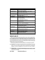
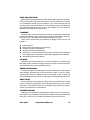
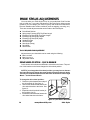
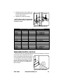
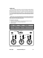
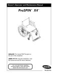
OWNER’S MANUAL PRIDE MOBILITY PRODUCTS CORP. EXETER, PA ST. CATHARINES, ON 1-800-800-8586 www.pridemobility.com INFORMATION LABELING Symbols are used throughout this owner's manual and on this product to convey important information regarding proper use, care, and maintenance. WARNING! Failure to follow designated procedures can cause either personal injury, component damage, or malfunction (black symbol on yellow triangle with black border). MANDATORY! These actions should be performed as specified. Failure to perform mandatory actions can cause injury to personnel and/ or damage to equipment (white symbol on blue dot with white border). PROHIBITED! These actions should be prohibited. These actions should not be performed at any time or in any circumstances. Performing a prohibited action can cause injury to personnel and/or damage to equipment (black symbol with red circle and red slash). Symbols below are used on this product. Please read the information associated with each of the symbols presented and follow accordingly. MANDATORY! Read and follow the information in the owner’s manual. MANDATORY! Maximum seating weight. This owner’s manual is compiled from the latest specifications and product information available at the time of publication. We reserve the right to make changes as they become necessary. Any changes to our products may cause slight variations between the illustrations and explanations in this manual and the product you have purchased. Copyright 2004 Pride Mobility Products Corp. INFMANU2121/RevC/Aug04 2 www.pridemobility.com Pride Stylus TABLE OF CONTENTS INFORMATION LABELING ......................................................... 2 SAFETY ...................................................................................... 4 PURCHASERS AGREEMENT TO ENSURE SAFE OPERATION ............................ 4 CONTACT US ..................................................................................................... 5 PRIDE OWNERS CLUB ....................................................................................... 5 THE PRIDE STYLUS ...................................................................... 6 WEIGHT CAPACITY ........................................................................................... 7 USING THE PRIDE STYLUS ........................................................... 8 UNFOLDING ...................................................................................................... 8 FOLDING ........................................................................................................... 8 TRANSPORTING YOUR PRIDE STYLUS ................................................................ 9 PRE-RIDE CHECKS ............................................................................................ 9 PREPARING YOUR WHEELCHAIR FOR TRANSFER ......................................... 10 REACHING AND BENDING ............................................................................ 11 TIPS FOR SAFE USE ........................................................................................... 12 PRIDE STYLUS ADJUSTMENTS................................................... 14 DRIVE WHEEL POSITION - QUICK-RELEASE ................................................... 14 DRIVE WHEEL POSITION - BOLT-ON ............................................................... 15 SWING-AWAY FOOTREST (SFR) FOOT PLATE LENGTH .................................... 16 ELEVATING LEG REST (ELR) FOOT PLATE LENGTH........................................... 16 ELR CALFPAD .................................................................................................. 17 ELR ANGLE ...................................................................................................... 17 SEATBACK HEIGHT ........................................................................................... 17 ARMREST HEIGHT (OPTIONAL) ........................................................................ 18 SEAT ANGLE (DUMP) ....................................................................................... 18 MAINTENANCE ....................................................................... 20 PREVENTIVE MAINTENANCE .......................................................................... 20 CORRECTIVE MAINTENANCE ........................................................................ 22 OPTIONAL ACCESSORIES ....................................................... 22 OXYGEN TANK HOLDER ................................................................................. 22 ANTI-TIP WHEELS .............................................................................................. 22 WARRANTY ............................................................................. 22 Pride Stylus www.pridemobility.com 3 SAFETY WELCOME to Pride Mobility Products Corporation (Pride). The product you have purchased combines state-of-the-art components with safety, comfort, and styling in mind. We are confident that these design features will provide you with the conveniences you expect during your daily activities. Once you understand how to safely operate and care for this product, it should give you years of trouble free operation and service. Read and follow all instructions, warnings, and notes in this manual before attempting to operate this product for the first time. In addition, your safety depends upon you, as well as your provider, caretaker, or healthcare professional in using good judgement. If there is any information in this manual in which you do not understand, or if you require additional assistance for setup or operation, please contact your authorized Pride Provider. Failure to follow the instructions in this manual and those located on your product can lead to personal injury and/or damage to the product, including voiding the warranty. PURCHASER’S AGREEMENT TO ENSURE SAFE OPERATION By accepting delivery of this product, you promise that you will not change, alter, or modify this product or remove or render inoperable or unsafe any guards, shields, or other safety features of this product; fail, refuse, or neglect to install any retrofits kits from time to time provided by Pride to enhance or preserve the safe use of this product. 4 www.pridemobility.com Pride Stylus CONTACT US We want to hear your questions, comments, and suggestions regarding this owner’s manual and our products. We would also like to hear about the service you receive from your authorized Pride Provider. Please feel free to contact us directly. Pride Mobility Products Corporation Attn: Customer Care Department 182 Susquehanna Avenue Exeter, PA 18643-2694 800-424-8295 [email protected] www.pridemobility.com Please notify us if you change your address, so we can keep you apprised of important information regarding safety, new products, and new options that can increase your ability to use and enjoy this product. PRIDE OWNERS CLUB We invite you to register your product’s warranty and enroll in the Pride Owners Club. Fill out and return your enclosed registration card or visit Pride’s web site at www.pridemobility.com. Select “Owners Club/Web Talk” to enter a site dedicated to current and potential Pride product owners. This site contains interviews, stories, recreation ideas, daily living tips, product and funding information, and interactive message boards. Our message boards enable you to communicate with other Pride customers as well as Pride representatives who address your questions. As a registered member, you will have access to the most interactive and honest educational venue available for people with mobility needs, their families, and friends. Keep the following information on your Pride product. We need to know this when you contact us. Authorized Pride Provider:_______________________________________ Address:_______________________________________________________ Phone Number:____________________ Purchase Date:________________ If you ever lose or misplace your product registration card or owner’s manual, contact us and we will be glad to send you a new one immediately. Pride Stylus www.pridemobility.com 5 THE PRIDE STYLUS The Pride Stylus is designed to meet the requirements of HCPCS Code K0004. It is a dual-position, rear-wheel drive wheelchair designed to operate both indoors and outdoors on smooth surfaces. SEAT CANE HANDLES ARMRESTS SEAT BASE PARK BRAKE SEATBACK REAR FLAP HANDRIM ARMREST LATCH TIRE PARK BRAKE HEEL LOOPS CROSS FRAME FOOT PLATE(S) CASTER FORK SIDE FRAME CASTER WHEEL FOOT RIGGING (SWING-AWAY FOOTREST SHOWN) SPOKES DRIVE WHEEL Figure 1. Pride Stylus 6 www.pridemobility.com Pride Stylus Pride Stylus Specifications Table 29 lbs. (without foot riggings) 33 lbs. (with foot riggings) Seat Dimensions: 16 in. X 16 in., 18 in. X 16 in., 18 in. X 18 in., 20 in. X 16 in., 20 in. X 18 in. Back Height: 15 in.—17 in. Seat-to-Floor Height: Standard wheel: 18.5 in.—19.5 in. adjustable Super-Hemi (SH) wheel: 15.5 in. Seat Upholstery: Adjustable tension Drive Wheels: 24 in. Mag rim with aluminum handrim and solid* tire 22 in. Mag (optional) 20 in. Spoke (optional) 24 in. Pneumatic tire (optional) Axle Mount: 6-position, Quick-release 2-position, Bolt-on Caster Wheels: 8 in. solid* tire 6 in. or 5 in., solid* tire (optional) Caster Fork: 4-position axle Armrests: Flip-back, desk-length Height-adjustable (optional) Foot Riggings: 70° swing-away, industry-compatible, through-bolted foot plate extension tubes, reinforced hanger brackets Elevating Leg Rests (optional) Brakes: Push-to-lock, adjustable, Pull-to-lock (optional) Frame Finish: Silver Vein Accessories: Oxygen Tank Holder (optional) Anti-tip Wheels (optional) Weight Capacity: 250 lbs. *polyurethane Base Weight: WEIGHT CAPACITY Refer to the Pride Stylus Specifications Table for the maximum weight capacity. Exceeding the maximum weight capacity may cause your wheelchair to become unstable and tip over. It is also likely to damage your wheelchair. Pride will not be responsible for injuries and/or property damage resulting from failure to observe weight limitations. Damage to your wheelchair caused by exceeding the weight limit is not covered by the warranty. The following conditions increase the possibility of exceeding the weight limit: £ Rear Flap - The rear flap is for pocket items such as cell phones, keys, and papers. There are no other storage areas on you wheelchair. Carrying heavy baggage or tying heavy baggage to your wheelchair can make it unstable. £ Multiple Riders - Your wheelchair was designed to carry one person. Carrying more than one person will likely exceed the weight limit and cause your wheelchair to become unstable. Pride Stylus www.pridemobility.com 7 MODIFICATIONS Under no circumstances should you modify, add, remove, or disable any feature, part, or function of your wheelchair unless under the direction of an authorized Pride Provider. USING THE PRIDE STYLUS The Pride Stylus is a manual wheelchair. Either an attendant pushes it, or you move it by gripping the handrims and turning them in the desired direction of travel. You steer it by turning one wheel faster than the other. To stop the wheelchair, you apply pressure to both handrims until the wheelchair comes to a complete stop. UNFOLDING The Pride Stylus is a folding wheelchair. You must unfold it completely before sitting in it. PUSH TO ENGAGE To unfold the Pride Stylus: 1. Engage both park brakes. See figure 2. NOTE: Your wheelchair may be equipped with either push to lock or pull to lock brakes. 2. Place the palm of your hands on each seat base rail. See figure 3. 3. Press down until the seat base rails are locked into place. Figure 2. Right Park Brake Engaged (Push-to-lock shown.) FOLDING Folding the wheelchair makes it easier to carry and store. The folded width is 11.75 in. SEAT BASE RAILS To fold the Pride Stylus: 1. Engage both park brakes. See figure 2. 2. Hold the seat base by the center at the front and at the back. See figure 4. 3. Pull up on the seat base until both wheels close together. Figure 3. Unfolding the Pride Stylus 8 www.pridemobility.com Pride Stylus TRANSPORTING YOUR PRIDE STYLUS Currently, there are no approved standards for tie-down systems used to secure your wheelchair inside a moving vehicle of any type while you or anyone else is seated in the wheelchair. Although your wheelchair may be equipped with a positioning belt, this belt is not designed to provide proper restraint during motor vehicle transport. Anyone travelling in a motor vehicle should be properly secured in the motor vehicle seat with safety belts securely fastened. The Pride Stylus was designed to be folded and stored in a secure location such as in the trunk of a car. NOTE: You can also remove the drive wheels to make the wheelchair more compact. See figure 13. To lift or carry the Pride Stylus: 1. Fold the Pride Stylus. 2. With one hand, grab and squeeze together both seat cane handles. See figure 5. 3. With the other hand, grab and squeeze together both seat base rails. Figure 4. Folding the Pride Stylus SEAT CANE HANDLES SEAT BASE RAILS Figure 5. Lifting Points WARNING! Prevent injury. If you remove the drive wheels, make sure the quick-release mechanisms snap into place when reinstalling a wheel. See figure 13. PRE-RIDE CHECKS Pride recommends that you practice using the wheelchair in the presence of a trained attendant. A trained attendant is a healthcare professional specifically trained to assist wheelchair users in various daily activities. Perform the following pre-ride checks before using your wheelchair to help ensure your wheelchair operates smoothly and safely: ü ü ü Check for loose or missing screws, nuts, and bolts. Replace or tighten them as necessary. Check the tires. Look for uneven wear, holes, or tire/rim separation. If they look excessively worn, then have them replaced. Visually inspect pneumatic tires for punctures. Confirm correct air pressure as marked on the side of the tire. Always use a pressure-regulated air supply to inflate the tires. Pride Stylus www.pridemobility.com 9 ü ü Check the handrims. Make sure that they are fastened securely to the wheels. Check the park brakes. Make sure they work properly. If they don’t, instructions on how to adjust them are provided in this manual. WARNING! The park brakes are designed to keep your chair stationary while you are parked. They are not designed to stop the wheelchair during driving. Do not use either of the park brakes to stop the wheelchair while driving it. This can cause your wheelchair to become unstable and tip. Failure to heed can result to personal injury and/or damage to your wheelchair ü ü ü ü ü Check that your wheelchair drives straight and does not pull to one side. Pulling to one side could be an indication that a wheel bearing needs to be replaced. Check the caster wheels. Look for uneven wear, holes, or tire/rim separation. If they look excessively worn, then have them replaced. Make sure they swivel freely. If they don’t, the swivel bearings may need to be replaced. Check the seat for sagging, rips, or tears. If your wheelchair is equipped with a positioning belt, make sure it is fastened securely to the wheelchair and there are no rips or tears. Check the anti-tip wheels (optional equipment). Make sure that they are attached securely. If you discover a problem, contact your authorized Pride Provider for assistance. PREPARING YOUR WHEELCHAIR FOR TRANSFER There are a variety of methods you can use to transfer onto or off of your wheelchair. Regardless of the method you use, transferring onto or off of your wheelchair safely requires practice and, in some cases, the presence of a certified healthcare professional or trained attendant. Make sure you have a certified healthcare professional or trained attendant present while learning to properly transfer yourself. SQUEEZE TO RELEASE To prepare your wheelchair for transfer: 1. Move the wheelchair as close as possible to you (or to your transfer destination). 2. Turn both caster wheels toward you (or toward your transfer destination) to improve wheelchair stability during transfer. 3. Make sure that both park brakes are engaged. See figure 2. 10 Figure 6. Flip-up Armrest Latch www.pridemobility.com Pride Stylus 4. If necessary flip up an armrest. See figure 6. WARNING! Reduce the risk of your wheelchair to tipping. Do not use armrests to support yourself during transfer. Failure to heed can result in personal injury and/or damage to your wheelchair. 5. Either remove the foot riggings or move them aside. See figure 7. You can also Figure 7. Foot Rigging Removal flip-up the foot plates. This will help to prevent your feet from being caught on the foot riggings during the transfer. If you use the foot riggings to support yourself during transfer, you risk tipping your wheelchair. REACHING AND BENDING Reaching and bending when seated in your wheelchair requires practice. Pride recommends that you determine your personal limitations, and practice bending and reaching in the presence of a certified healthcare professional or trained attendant. Keep the following in mind when reaching or bending: £ Come to a complete stop and engage the park brakes before attempting to reach or bend. £ When reaching, bending, or leaning while seated in your wheelchair, it is important that you maintain stability to keep the wheelchair from tipping. £ Reaching, bending, or leaning down to pick up objects between your knees may change your center of gravity and the weight distribution of your wheelchair and cause your wheelchair to tip over. Pride Stylus www.pridemobility.com 11 TIPS FOR SAFE USE The Pride Stylus was designed to be simple to use on smooth, level surfaces. However, you may encounter situations that require a higher level of skill. It is for these situations that you will benefit from practicing with a trained attendant. Pride performs extensive testing on our wheelchairs. From the results of these tests, we have determined that the following conditions are outside the normal operating range of the Pride Stylus and require the presence of a certified healthcare professional or trained attendant. PERFORMING “WHEELIES” Performing “wheelies” (lifting the caster wheels off the ground to travel over an object) requires skill, balance, and hours of practice in the presence of a trained attendant. If you attempt to perform a “wheelie” and do not have the skill to do so alone, you risk tipping over backward. Do not perform “wheelies” unless you are skilled enough to do so. CLIMBING INCLINES The maximum incline angle your wheelchair can climb safely on solid ground is 5° at maximum weight capacity. Most handicap access ramps are pitched at 5°. Any attempt to climb a steeper incline may put your wheelchair in an unstable position, especially if the incline is rough or uneven terrain. See figure 8. Figure 8. Maximum Safe Incline Angle (Ascending and Descending) CURBS AND OTHER OBSTACLES Pride recommends driving around curbs or other obstacles, rather than over them. However, there may be some situations where it may be necessary to climb a curb. If you are going to attempt to climb onto a curb, approach it slowly and straightforward. See figures 9 and 10. Figure 9. Incorrect Curb Approach 12 Figure 10. Correct Curb Approach www.pridemobility.com Pride Stylus STAIRS AND ESCALATORS Most multilevel buildings that have stairs and escalators also have elevators. Pride recommends that you use the elevator to move to a different level. Under no circumstances should you use escalators. If you must use steps, then we recommend that you seek assistance. Do not attempt to have your wheelchair proceed backward down any step, curb, or other obstacle. This may cause the wheelchair to tip and cause personal injury. CORNERING Always exercise common sense when cornering. If the situation arises where you have to negotiate a sharp corner, reduce your speed and lessen the sharpness of the turn. This greatly reduces the possibility of a tip or fall. Other factors which affect the possibility of tipping include, but are not limited to: £ £ £ £ £ cornering speed steering angle (how sharply you are turning) cornering on uneven road surfaces cornering on inclined road surfaces cornering on a surface that has different types of traction (such as passing from a grassy area to a paved area, especially at high speed while turning) £ making abrupt directional changes OFF-ROAD Pride does not recommend that you use your wheelchair on anything other than solid, smooth surfaces. Driving your chair on uneven surfaces can cause your wheelchair to become unstable and tip over. STREETS AND ROADWAYS Consult your local laws concerning the use of your wheelchair on public streets and roadways. Be aware that it may be difficult for traffic to see you. When crossing public streets or roadways, wait until your path is clear of traffic and then proceed with extreme caution. Always obey all local pedestrian traffic rules. MEDICATIONS Some medications may impair your ability to drive your wheelchair in a safe manner. Consult your physician if you are taking prescribed or over-the-counter medication. This includes alcohol. Your prescription may impair your ability to operate your wheelchair in a safe manner. INCLEMENT WEATHER Although your wheelchair was designed for outdoor use, we do not recommend that you use it outdoors during inclement weather. Driving your wheelchair in the rain or snow or on icy surfaces increases the risk of an accident. Pride Stylus www.pridemobility.com 13 PRIDE STYLUS ADJUSTMENTS You must have your Pride Stylus set up by your authorized Pride Provider prior to initial use. If you make adjustments to the Pride Stylus without proper guidance, you can change your center of gravity and cause the wheelchair to become unstable under certain conditions (such as stopping, cornering, etc.). There are several adjustments that can be made to the Pride Stylus: £ £ £ £ £ £ £ £ £ £ Drive Wheel Position Swing-away Footrest (SFR) Foot Plate Length Elevating Leg Rest (ELR) Foot Plate Length Elevating Leg Rest (ELR) Calfpad Elevating Leg Rest (ELR) Angle Seatback Height Armrest Height Seat Angle (Dump) Park Brake Seat Tension TOOLS REQUIRED FOR ADJUSTMENT Adjustments to your wheelchair can be made using the following: £ Metric sockets £ Metric hex keys £ Adjustable wrench DRIVE WHEEL POSITION - QUICK-RELEASE Quick-release drive wheels are attached to a bracket on the frame. The position of this bracket on the frame changes the drive wheel position. NOTE: If you change the drive wheel position, you may have to shorten the foot plate length, change the caster height, and adjust the park brake. Consult your authorized Pride Provider. Also refer to the Seat-to-Floor Height Matrix — Quick-Release Wheels. To change the drive wheel position: 1. Press the quick-release button and pull the drive wheel off. See figure 11. 2. Remove the hardware that fastens the drive wheel bracket to the frame. See figure 12. 3. Reposition the drive wheel bracket (either position A or B). 4. Reinstall the hardware that fastens the drive wheel bracket to the frame. QUICK-RELEASE BUTTON Figure 11. Quick-Release Drive Wheel 14 www.pridemobility.com Pride Stylus 5. Reinstall the drive wheel. Make sure that the wheel axle is snapped securely into the frame bracket. 6. Repeat for the other drive wheel. POSITION A POSITION B NOTE: When using an oxygen tank holder, the drive wheel bracket must be in position A only. Figure 12. Drive Wheel Bracket Seat-to-Floor Height Matrix – Quick-Release Wheels S-T-F Height Caster Axle Position* Rear Wheel / Position 19.5 in. 8 in. 3 24 in. / bottom hole 18.5 in. 8 in. 4 24 in. / middle hole 18.5 in. 6 in. 2 24 in. / middle hole 18.5 in. 6 in. 3 22 in. / bottom hole 18.5 in. 8 in. 4 22 in. / bottom hole 17.5 in. 8 in. 4 24 in. / top hole 17.5 in. 8 in. 4 22 in. / top hole 17.5 in. 6 in. 4 24 in. / top hole 17.5 in. 6 in. 4 22 in. / middle hole 16.5 in. 6 in. 4 22 in. / top hole 16.5 in. 5 in. 3 22 in. / middle hole 15.5 in. 5 in. 4 22 in. / top hole 15.5 in. 5 in. 4 20 in. / middle hole 14.5 in. 5 in. 4 20 in. / top hole *Hole Position from Bottom DRIVE WHEEL POSITION - BOLT-ON Bolt-on drive wheels are attached directly to the frame. See figure 13. Bolt-on drive wheels can be attached to the frame in one of two positions. When the drive wheel is in the top hole, the seat-to-floor height is 18.5 in. When the drive wheel is in the bottom hole, the seat-to-floor height is 19.5 in. Refer to the Seat-to-Floor Height Matrix — Bolt-on wheels. Figure 13. Bolt-on Drive Wheel Pride Stylus www.pridemobility.com 15 To change the drive wheel height: 1. Remove the hubcap. 2. Remove the nut from the bolt. See figure 13. 3. Remove the drive wheel. 4. Reposition the drive wheel. 5. Reinstall the nut and bolt that fastens the drive wheel to the frame. 6. Reinstall the hubcap. 7. Repeat for the other drive wheel. S-T-F Height 19.5 in. 18.5 in. Seat-to-Floor Height Matrix – Bolt-On Caster Position Drive Wheel Position 8 in. (second from bottom hole) 24 in. (bottom hole) 8 in. (top hole) 24 in. (top hole) SWING-AWAY FOOTREST (SFR) FOOT PLATE LENGTH You can change the SFR foot plate length between 12 – 17 inches in 1-in. increments. This length is measured from the SFR foot plate to the top of the SFR. See figure 14. To change the SFR foot plate length: 1. Remove the screw from the SFR. 2. Adjust the foot plate to the desired length. 3. Reinstall the screw into the SFR. 4. Repeat for the other side. ELEVATING LEG REST (ELR) FOOT PLATE LENGTH SCREW Figure 14. SFR Foot Plate Adjustment You can change the ELR foot plate length between 12 – 17 in. This length is measured from the ELR foot plate to the top of the ELR. See figure 15. To change the ELR foot plate length: 1. Remove the cap. 2. Loosen the bolt on the side of the ELR. 3. Adjust the foot plate to the desired length. 4. Tighten the bolt on the side of the ELR. 5. Reinstall the cap. 6. Repeat the procedure for the other side. BOLT CAP Figure 15. ELR Foot Plate Adjustment 16 www.pridemobility.com Pride Stylus ELR CALFPAD You can change the ELR calfpad to one of three different positions. See figure 16. CALFPAD To change the ELR calfpad position: 1. Rotate the calfpad to unlock it. 2. Move it up or down to the desired position. 3. Rotate the calfpad back to lock it. 4. Repeat for the other side. THREE POSITIONS ELR ANGLE You can change the ELR angle to one of seven positions. See figure 17. Figure 16. ELR Calfpad Adjustment To change the ELR angle: 1. Pull the ELR up to the desired position. 2. Pull back on the ELR release lever and lower the ELR to the desired position. RELEASE LEVER SEATBACK HEIGHT You can adjust the seatback to one of three different heights. The adjustment range is 3 inches in 1-in. increments. See figure 18. Figure 17. ELR Angle Adjustment To adjust the seatback height: 1. Remove the bolts to unfasten the seat canes from each side of the frame. 2. Slide the canes up or down into one of the three holes for the desired height. 3. Use the bolts to refasten the seat canes into the frame. SEAT CANES BOLTS FRAME Figure 18. Seatback Height Adjustment Pride Stylus www.pridemobility.com 17 ARMREST HEIGHT (OPTIONAL) The armrest has seven holes that are spaced 1 in. apart. See figure 19. RELEASE PIN To adjust the armrest: 1. Pull back the release pin located on the armrest. 2. Move the armrest up or down. 3. Release the pin. 4. Make sure the armrest locks into place. SEAT ANGLE (DUMP) Figure 19. Armrest Height Adjustment The position of the caster wheels affects the angle of the seat (dump). There are four holes in the caster fork. By changing the location of the caster wheel on the fork, you change the seat angle. See figure 20. NOTE: You can also adjust the seat angle by raising or lowering the drive wheel. See “Drive Wheel Position.” CASTER FORK CASTER WHEEL To change the seat angle: 1. Remove the hardware that fastens the caster wheel to the caster fork. Figure 20. Caster Wheel Position 2. Reposition the caster wheel on the caster fork. 3. Reinstall the hardware that fastens the caster wheel to the caster fork. 4. Repeat the procedure for the other side. WARNING! Changing the seat angle may adversely affect stability and cause the wheelchair to tip over. Failure to heed can result in personal injury and/or damage to your wheelchair 18 www.pridemobility.com Pride Stylus CASTER ANGLE When you change the seat angle, you must also change the caster angle so that the caster wheels remain at a 90° angle to the ground. There are three possible caster angles. See figure 21. If the front of the seat is higher than the rear, the caster assembly should be in position 1. If there is little or no seat dump (i.e., the seat is parallel to the ground), the caster assembly should be in position 2. If the rear of the seat is higher than the front, the caster assembly should be in position 3. NOTE: There are two bolts that fasten the caster wheel assembly to the frame. The bolt shafts are offset to the heads. The bolt shafts must be positioned either fore or aft relative to the holes. To change the caster angle: 1. Remove the bolts that fasten the caster wheel assembly to the frame. 2. Reposition the bolts according to the table below. 3. Tighten the bolts. Caster Position 1 2 3 Top Bolt Position Fore Fore Aft BOLT HEAD Bottom Bolt Position Aft Fore Fore Caster Wheel Angle 95° 90° 85° BOLT SHAFT AFT FORE POSITION 1. POSITION 2. TOP BOLT POSITION 3. BOTTOM BOLT Figure 21. Caster Angle Adjustment Pride Stylus www.pridemobility.com 19 MAINTENANCE Maintenance is an important part of wheelchair ownership. There are two types of maintenance: preventive (routine) and corrective. Preventive maintenance enables you to help extend the life of your wheelchair by catching potential problems before it becomes necessary to correct them. Corrective maintenance is what you must do when your wheelchair needs immediate repair. PREVENTIVE MAINTENANCE In addition to your pre-ride checks, you can pay particular attention to your drive wheels and the overall appearance of your wheelchair. Keep your wheelchair clean. This will help prevent dirt and other contaminants from getting into places where it doesn’t belong, like the drive wheel bearings, the frame hinges, or the caster bearings. Drive wheel and caster bearings are sealed and do not require lubrication. DRIVE WHEELS AND CASTER WHEELS Worn tires can make your wheelchair difficult to drive. Check for drive tire and caster tire wear. If they are worn excessively, then replace them. If they appear to have worn unevenly, then contact your authorized Pride Provider before replacing them. Pneumatic tire tubes may be either patched or replaced. Though patching pneumatic tire tubes is a viable method of repair, we recommend replacing the pneumatic tire tube. We also recommend using a regulated air source. This will decrease the likelihood of overinflating the tire and causing it to burst. NOTE: Although you can remove the tube from the tire without first removing the drive wheel, we recommend removing the drive wheel first. To replace a pneumatic tire tube: 1. Remove the drive wheel from the frame. See figures 11 or 13. 2. Make sure that the tube is deflated completely. 3. Use several tire levers to pry the tire from the rim. Tire levers are available from a bicycle shop. 4. Remove the old tube. 5. Inflate the new tube with enough air so that it just starts to take shape, about 10 psi. WARNING! If your wheelchair is equipped with pneumatic tires, make sure they are inflated to the pressure recommended on the sidewall of the tire. Failure to heed can result in personal injury and/or damage to your wheelchair. 6. Insert the tube into the tire. 7. Use the tire levers to secure the tire back onto the rim. 8. Inflate the tire to the pressure recommended on the sidewall. Always use a regulated air source. 9. Reinstall the drive wheel to the frame. Make sure that the wheel axle is snapped securely into the frame bracket. 20 www.pridemobility.com Pride Stylus PARK BRAKES After several months of use, you may find it necessary to adjust the park brakes so that they lock securely when engaged. You also may need to adjust them after changing the drive wheel position. HARDWARE ME FRA TIRE To adjust each park brake: 1. Engage the park brake. See figure 2. BRAKE The distance that the park brake blade BLADE should travel into the tire is 1/8 in. for pneumatic tires and 1/4 in. for solid tires. Figure 22. Park Brake Adjustment 2. Disengage the park brake. (Push-to-lock shown.) 3. Loosen the hardware that fastens the park brake to the frame. See figure 22. 4. Reposition the park brake. 5. Tighten the hardware that fastens the park brake to the frame. 6. Reengage the park brake and note the position of the blade. 7. Reposition the park brake if necessary. 8. Repeat the procedure for the other side. CASTER WHEEL SWIVEL Caster wheels that have difficulty swiveling may indicate that the bearings need to be changed. If they are not swiveling freely, contact your authorized Pride Provider immediately. SEAT TENSION After a period of use, you may find it necessary to adjust the seat tension. To adjust the seat tension: 1. Loosen the screws that attach the seat to the side rail on the left side (side with hook and loop). See figure 23. 2. Unfasten the hook and loop. 3. Grab the bottom flap and pull the seat tight. 4. Fasten the hook and loop. 5. Tighten the screws. Make sure that the plastic washers are on top of the fabric. PULL TO TIGHTEN Figure 23. Seat Tension Adjustment CLEANING To keep your wheelchair clean, use a damp cloth and wipe it down. Don’t use a hose. This could force moisture into the caster swivel or the drive wheel hub. Always use soapy water on the seat and dry it thoroughly before using. Pride Stylus www.pridemobility.com 21 CORRECTIVE MAINTENANCE If you feel that your wheelchair’s performance has degraded or is not operating correctly, contact your authorized Pride Provider. All components should be serviced by an authorized Pride Provider while the unit is still under warranty. We do not recommend that you remove any parts and send them back for repair without first contacting your authorized Pride Provider. Contact your authorized Pride Provider for a list of authorized service facilities or you can visit us at www.pridemobility.com. REPLACEMENT PARTS Replacement parts are available from your authorized Pride Provider. OPTIONAL ACCESSORIES Installation instructions for optional accessories are provided with the accessory. OXYGEN TANK HOLDER The oxygen tank holder mounts to the back of the wheelchair and is capable of carrying a 10-lb. tank. The anti-tip wheels must be used with the oxygen tank. Refer to the instructions that accompany the oxygen tank holder. MANDATORY! Install anti-tip wheels when the oxygen tank holder is installed. ANTI-TIP WHEELS Anti-tip wheels are available for the Pride Stylus. WARRANTY Pride warrants this product, so far as the same is of its own manufacture, to be free of defects in material and workmanship, when used by the purchaser under normal conditions, for (1) year after purchase. The side frames and crossframes are warranted for the life of the product to the original purchaser. The warranties herein specified shall not apply if the failure of any component of this product to satisfy such warranty is due to accident, neglect, misuse, improper transportation arranged by the purchaser or its agent, or causes other than ordinary use including operation contrary to Pride’s operating instructions or if any person other than Pride’s authorized personnel shall modify, adjust, or repair such product or perform any related service on it. It must be understood that the purchaser assumes full responsibility for the overall safe operation in the environment for which the product is intended to function. 22 www.pridemobility.com Pride Stylus Pride Stylus www.pridemobility.com 23 Quality Control - Stylus Thank you for making the Stylus your choice in wheelchairs. We have thoroughly inspected your Stylus. The following checkmarks indicate that it has been test driven and inspected. Inclusion of all Parts Performance Fit and Finish Date Inspected Inspector Serial # Pride keeps a more detailed report on file at the factory.