1
ENGLISH
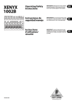
User Manual
XENYX 1002B
Ultra low-noise design,
10-input, 2-bus mic/line mixer
with optional battery
operation
Thank you
Table of Contents
Thank you for choosing the XENYX 1002B 10 input mixer. This mixer
Thank you...................................................................... 1
Important Safety Instructions.................................... 2
1. Before You Get Started............................................ 3
2. Audio Connections.................................................. 4
3. Controls and Connectors ....................................... 5
4. Gain Setting.............................................................. 6
5. Applications . ........................................................... 8
6. Specifications........................................................... 9
Limited waranty.......................................................... 11
Legal Disclaimer......................................................... 12
is packed with features like ultra low-noise XENYX mic preamps,
neo-classic “British” 3-band EQs, and stereo channels that allow
simultaneous mic and line input use, as well as both monitor and
FX sends on each channel. The 1002B can also operate on battery
power, a unique feature that allows you to record or perform on
the go or outdoors. The 1002B delivers everything you expect
from a powerful, small-format mixer. From broadcasting and video
dubbing to full band performance and recording, this versatile
piece of gear works wonders in a variety of applications.
This manual is available in English, German, Spanish and
Chinese. Download them by going to the appropriate product
page at:
www.behringer.com
XENYX 1002B User Manual
ENGLISH
2
Important Safety Instructions
[6]�
Clean only with dry cloth.
[7]�
Do not block any ventilation openings. Install in accordance
with the manufacturer’s instructions.
[8]�
Do not install near any heat sources such as radiators, heat
registers, stoves, or other apparatus (including amplifiers) that
produce heat.
*
[9]�
Do not defeat the safety purpose of the polarized or
Terminals marked with this symbol carry electrical current of
sufficient magnitude to constitute risk of electric shock. Use
only high-quality commercially-available speaker cables with ¼" TS
plugs pre-installed. All other installation or modification should be
performed only by qualified personnel.
*
{10}�
Place the power cord so that it is protected from being walked
This symbol, wherever it appears, alerts you to the presence of
uninsulated dangerous voltage inside the enclosure - voltage that
may be sufficient to constitute a risk of shock.
!
on and sharp edges. Be sure that the power cord is protected
particularly at plugs, convenience receptacles and the point
where it exits from the apparatus.
{11}�
The apparatus shall be connected to a MAINS socket outlet
with a protective earthing connection.
{12}�
Where the MAINS plug or an appliance coupler is used as
This symbol, wherever it appears, alerts you to important operating
and maintenance instructions in the accompanying literature.
Please read the manual.
!
grounding-type plug. A polarized plug has two blades with one
wider than the other. A grounding-type plug has two blades
and a third grounding prong. The wide blade or the third prong
are provided for your safety. If the provided plug does not fit
into your outlet, consult an electrician for replacement of the
obsolete outlet.
the disconnect device, the disconnect device shall remain
readily operable.
{13}�
Only use attachments/accessories specified by the
manufacturer.
{14}�
Use only with the cart, stand, tripod, bracket,
Caution
To reduce the risk of electric shock, do not remove the top cover
(or the rear section). No user serviceable parts inside. Refer servicing
to qualified personnel.
!
Caution
!
Caution
or table specified by the manufacturer, or
sold with the apparatus. When a cart is used,
use caution when moving the cart/apparatus
combination to avoid injury from tip-over.
{15}�
Unplug this apparatus during lightning
storms or when unused for long periods of time.
To reduce the risk of fire or electric shock, do not expose this
appliance to rain and moisture. The apparatus shall not be exposed
to dripping or splashing liquids and no objects filled with liquids,
such as vases, shall be placed on the apparatus.
These service instructions are for use by qualified service personnel
only. To reduce the risk of electric shock do not perform any
servicing other than that contained in the operation instructions.
Repairs have to be performed by qualified service personnel.
[1]�
Read these instructions.
[2]�
Keep these instructions.
[3]�
Heed all warnings.
[4]�
Follow all instructions.
[5]�
Do not use this apparatus near water.
{16}�
Refer all servicing to qualified service personnel. Servicing is
required when the apparatus has been damaged in any way,
such as power supply cord or plug is damaged, liquid has been
spilled or objects have fallen into the apparatus, the apparatus
has been exposed to rain or moisture, does not operate
normally, or has been dropped.
EN
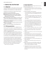
1. Before You Get Started
1.1 Shipment
Your XENYX 1002B was carefully packed at the factory and the
packaging is designed to protect the unit from rough handling.
Nevertheless, we recommend that you carefully examine the
packaging and its contents for any signs of physical damage
which may have occurred during transit.
◊ If the unit is damaged, please do NOT return it to
◊ BEHRINGER, but notify your dealer and the shipping
company immediately. Otherwise, claims for damage or
replacement may not be granted.
◊ We recommend that you use a flight case, so as to give your
power mixer optimum protection during use or transport.
◊ Always use the original packing carton to prevent damage
during storage or transport.
◊ Make sure that children cannot play unsupervised with the
device or its packaging.
◊ Please ensure proper disposal of all packing materials.
1.2 Online registration
Please do remember to register your new BEHRINGER equipment right after your purchase by visiting www.behringer.com
(alternatively www.behringer.de) and kindly read the terms and
conditions of our warranty carefully.
Should your BEHRINGER product malfunction, our goal is to
have it repaired as quickly as possible. To arrange for warranty
service, please contact the retailer from whom the equipment
was purchased. Should your BEHRINGER dealer not be located
in your vicinity, you may directly contact one of our subsidiaries.
Corresponding contact information is included in the original
equipment packaging (Global Contact Information/European
Contact Information). Should your country not be listed, please
contact the distributor nearest you. A list of distributors can be
found in the support area of our website (www.behringer.com).
Registering your purchase and equipment with us helps us
process your repair claims quicker and more efficiently.
Thank you for your cooperation!
3
1.3 Basic Operation
The XENYX 1002B is easy to use. Simply follow these steps to
achieve the best possible sound:
1. Plug the included power cable into the back of the mixer.
Plug the other end of the cable into a mains outlet. DO NOT
turn the mixer on yet.
2. Make all appropriate audio connections:
• Connect microphones to the MIC jacks using XLR cables.
• Connect line-level sources to the LINE IN jacks using ¼"
TS cables.
• Connect stereo sources (keyboard, drum machine) to one
of the stereo LINE IN jacks using a pair of ¼" TS cables.
• Connect a CD player to the 2 TRACK INPUT using ¼" or
RCA cables.
• See Applications chapter for more details and options.
3. Connect a monitoring source or speaker system. You may
connect powered studio monitors, powered loudspeakers or
a power amp to the MAIN OUTPUT jacks. You may also
connect a pair of headphones to the PHONES jack. Leave
powered speakers and/or power amps turned off until the
mixer has been powered on.
4. Turn all PAN/BAL and EQ knobs to their center (12 o’clock)
position. Set all other knobs and faders all the way down/off.
5. Once all connections have been made, you may turn the
mixer on.
6. After the mixer is turned on, you may also turn the speakers
or power amp on.
7. Set the input gain level for each channel using the GAIN
knob. While testing the audio source, turn the GAIN knob as
high as possible without allowing the CLIP LED to light. See
the Gain Setting section for details.
8. Raise the MAIN fader to 0. You may adjust it further as you
begin to set levels.
9. Adjust all channel volume faders until you achieve a balanced mix.
10. Make sure that the channel CLIP LEDs and MAIN CLIP
LEDs do not light frequently. If this happens, adjust the
respective GAIN or MAIN fader accordingly.
11. Congratulations! You have now set up a basic mix! The
1002B offers many other cool features as well, so continue
through the manual to make the most out of this powerful
little mixer.
ENGLISH
XENYX 1002B User Manual
XENYX 1002B User Manual
ENGLISH
4
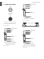
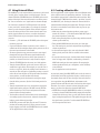
2. Audio Connections
Strain relief clamp
Sleeve
input
Tip
2 1
3
Sleeve
(ground/shield)
1 = ground/shield
2 = hot (+ve)
3 = cold (-ve)
output
1
Tip
(signal)
2
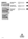
Unbalanced ¼" TS connector
3
Fig. 2.3: ¼" Unbalanced
For unbalanced use, pin 1 and pin 3 have to be bridged
Balanced use with XLR connectors
tip
tip
sleeve
Fig. 2.1: XLR Balanced
strain relief clamp
shield
sleeve
Fig. 2.4: RCA
sleeve
ring
strain relief clamp
tip
sleeve
ring
tip
sleeve
ground/shield
sleeve
ground/shield
ring
cold (-ve)
tip
hot (+ve)
ring
return (in)
For connection of balanced and unbalanced plugs,
ring and sleeve have to be bridged at the stereo plug.
Balanced 1/4" TRS connector
Fig. 2.2: ¼" Balanced
tip
send (out)
Connect the insert send with the input and the
insert return with the output of the effects device.
Insert send return 1/4" TRS connector
Fig. 2.5: Insert cable
5
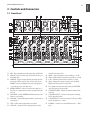
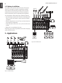
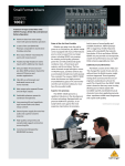
3. Controls and Connectors
3.1 Front Panel
[1] MIC – Plug a microphone into this input using an XLR cable.
[2] LINE IN – Plug a line-level source into this jack using a ¼"
TS or TRS cable.
[3] INS(ERT) – Plug an external dynamic processor into this
[4]
[5]
[6]
[7]
[8]
jack using a TRS to dual TS cable. You may also use the
INSERT jack as a pre-EQ/pre-fader send by plugging in a
¼" TS cable part way to the first click.
STEREO LINE IN – Plug in a stereo source using two ¼"
TS cables, or a single line-level source using the left input
jack only.
GAIN LINE – Adjusts STEREO LINE IN sensitivity, also
known as “gain setting.”
GAIN MIC – Adjusts MIC input sensitivity, also known as
“gain setting.”
CLIP – Lights when preamp begins to overload.
PAN/BAL – Adjusts the left-to-right positioning of the
[9]
[10]
[11]
[12]
[13]
[14]
[15]
[16]
[17]
channel in the stereo field.
HIGH – Adjusts frequencies above 10 kHz by +- 15 dB.
MID – Adjusts frequencies peaking at 700 Hz by +- 15 dB.
LOW – Adjusts frequencies below 50 Hz by +- 15 dB.
MON – Adjusts the amount of signal sent to the MON
SEND jack. This signal is sent pre-fader.
FX – Adjusts the amount of signal sent to the FX SEND
jack. This signal is sent post-fader.
CHANNEL FADER – Adjusts the channel volume in the
main mix.
2-TRACK OUTPUT – Connect to the inputs of recording
device using RCA cables.
2-TRACK INPUT – Connect to outputs of CD, tape or MP3
player using RCA or ¼" cables.
PHONES – Connect a pair of headphones with a ¼" TRS
plug.
ENGLISH
XENYX 1002B User Manual
XENYX 1002B User Manual
ENGLISH
6
[18] MAIN OUTPUT – Connect to the inputs of a power amp or
powered speakers using ¼" TS cables.
[19] FX SEND – Connect to the input of an external effects
device using a ¼" TS cable.
[20] MON SEND – Connect to the input of a powered monitor or
monitor power amp using a ¼" TS cable.
[21] VU CLIP – Lights when the MAIN OUTPUT signal begins
to overload.
[22] PHANTOM – Sends 23V of power to the XLR MIC inputs
[23]
[24]
[25]
[26]
[27]
for use with condenser microphones. When used with
batteries, 18V of power is supplied.
VU METER – Displays the MAIN OUTPUT signal level.
MON SEND – Adjusts the output at the MON SEND jack.
FX SEND – Adjusts the output at the FX SEND jack.
PHONES – Adjusts the output at the PHONES jack.
MAIN FADER – Adjusts the overall output of the mixer
through the MAIN OUTPUTS. It also affects the signal at
the PHONES out and 2-TRACK OUTPUT.
3.2 Rear Panel
[28] AC POWER IN – Connect the mains power cable into
this input.
[29] POWER ON – Turns the mixer’s power on and off.
4. Gain Setting
It is very important to set each channel’s GAIN knob correctly
in order to get the maximum amount of signal headroom and
least amount of noise possible. Setting the GAIN too low could
make that channel too quiet to mix properly, while setting it too
high will cause clipping and distortion. Stereo channels 3/4, 5/6
and 7/8 allow the MIC and LINE inputs to be used in parallel
thanks to the dedicated GAIN knobs for each input. Follow these
instructions to set the gain for each channel and situation:
• Plug the audio source into the channel input (XLR or ¼").
• Sing into the microphone or play the line-level source at the
volume you will ultimately use during recording or performance. If you set the gain for a vocal mic by saying “check”
into it, this gain setting will probably not be as loud as the
actual vocal performance. Setting the gain this way will
lead you to set the gain too high, which may cause the extra
loud vocal performance to overload and distort. Likewise, if
checking a mic that will record a saxophone, make sure the
performer plays close to the mic while setting the gain. For
keyboards, do not change the output volume of the keyboard
after the mixer’s gain has been set.
• Turn the GAIN knob clockwise until the red CLIP LED lights
up. This means the channel has begun to overload (too much
signal is allowed in).
• Turn the GAIN knob counterclockwise a small amount, then
sing or play again. Ideally, the GAIN knob should be set as
high as possible while allowing the CLIP LED to only light
occasionally, if at all.
If you must use both the MIC and LINE inputs on channels 3/4,
5/6, or 7/8, you can adjust the gain setting for each source individually thanks to the dedicated GAIN knobs. The channel fader
affects the level of both sources, so achieving a good balance
between the 2 inputs can be tricky.
• Set the gain for the MIC input using the GAIN MIC as
described above.
• Set the gain for the LINE input(s) using the GAIN LINE as
described above.
• Both GAIN knobs share the same CLIP LED, so when both
sources are in use at the same time, neither input should
cause the LED to light. If this happens, turn each GAIN knob
down one at a time to determine which is overloading.
• Raise the channel fader so that both sources are audible in
the overall mix. Ideally, they will already be balanced and not
require further adjustment.
• If one source is too quiet with the fader turned up, turn the
louder source’s GAIN knob down a bit, then raise the fader to
the appropriate level. DO NOT simply turn the quiet source’s
GAIN knob up until it is loud enough, as this will likely cause
clipping and distortion.
4.1 Using External Effects
The 1002B lets you use external effects processors to add a touch
of reverb, delay, or other effects to various channels. Use the
channel FX knobs, FX SEND knob and FX SEND jack to send a
portion of the signal from several channels to an effects processor. You can insert the “wet” signal back into the mix through
one of the stereo channels. The FX signal from each channel
is sent “post-fader,” meaning that as you change the channel’s
volume, you also change how much of that channel’s signal is
sent to the effects processor. This ensures that the mix of wet
and dry signal remains the same as you adjust the channel
volume. Follow these steps to incorporate external effects in
your mix:
• Connect a ¼" TS cable from the FX SEND jack to the input of
the effects processor.
• If you would like the effects to operate in stereo, connect ¼"
cables from the left and right outputs of the processor to one of
the stereo input channels on the 1002B.
• For mono operation, most processors return a mono signal
through the left output. This mono signal should then be
routed into the left input on one of the mixer channels. If
possible, use channel 9/10 since it only allows line inputs.
• Turn the FX SEND knob to the center (12 o’clock) position.
• Turn the channel FX knob up for each source to which you
would like to apply effects. For example, you can add a lot of
reverb to a vocal mic, while only adding a small amount to a
snare drum. This will just be a preliminary setting as you will
not be able to hear the effect yet. Keep the knobs around the
center position; you will fine-tune them shortly.
• Adjust the input gain for the channel receiving the output
from the effects processor. (See the Gain Setting section for
details.)
• Turn the channel fader up to 0 on the channel receiving the
signal back from the processor. DO NOT turn the FX knob
on that channel up at all! Your sound system will become
haunted with screaming banshees.
• You should now hear the selected effect on the channels that
are sending signal to the processor. Adjust the channel FX
knobs to get the effect mix just right.
• NOTE: The processor will likely have its own VU meters to
monitor the incoming signal level. If the processor’s meter
begins clipping, turn down the FX SEND knob on the 1002B.
See the Applications section for details.
7
4.2 Creating a Monitor Mix
For live applications, audio engineers often send different mixes
to the audience and to the performing musicians. To allow this,
the 1002B is equipped with a dedicated monitor send bus. Each
channel features a MON knob that sends a “pre-fader” signal to
the MON OUT jack, allowing the channel’s volume fader to be
adjusted without affecting the monitor mix. The signal can also
be used as a second effects send. Follow these steps to set up a
basic monitor mix:
• Make sure the powered monitor speaker or power amp is
turned off. Connect a ¼" TS cable from the MON OUT jack to
the powered speaker or power amp.
• Turn on the powered speaker or power amp, and then turn the
volume up about half way.
• Turn the MON SEND knob to the center (12 o’clock) position. This setting may need to be adjusted later depending on
volume requirements.
• As the musicians begin to play, turn each channel’s MON
knob up slowly until each source is audible in the monitor
mix.
• It may take some time to get a balanced mix that all the musicians are happy with. If possible, avoid turning a channel’s
MON knob much past the center position. Do not point the
monitor speakers directly at a microphone, as this will likely
cause feedback.
See the Applications section for details.
As previously stated, the MON SEND jack can also be used as a
second effects send. This application requires a similar setup to
the normal effects send, but since the signal from each channel
is sent pre-fader using the MON knob, adjustments to the
channel’s volume will affect the mix of wet and dry effect signal.
Therefore, if you alter a channel’s volume during the performance, you must also adjust that channel’s MON knob.
• NOTE: When using the MON SEND for effects, if you neglect
to change a channel’s MON knob while turning that channel’s
volume fader all the way down, you will still hear the effected
signal coming through the mix. This problem happens because
the signal routes “pre-fader,” but the normal FX SEND bus
will not experience this issue.
ENGLISH
XENYX 1002B User Manual
XENYX 1002B User Manual
ENGLISH
8
4.3 Battery Installation
The 1002B can be powered by three 9V batteries. This feature
allows you, for example, to capture a high-quality recording
while sitting on the beach with your laptop. You’re no longer
tethered by an electrical outlet. You can still record with condenser mics thanks to the 18V of phantom power supplied by
two of the batteries. Follow these steps to install the batteries:
• Open the battery compartment located on the underside of the
mixer. You will need to remove a small screw with a Phillips
screwdriver.
• Slide the compartment cover out. There are slots for three batteries inside the compartment.
• Insert the batteries so that the + and – poles are in the correct
position.
• Replace the cover and tighten the screw.
The battery power will last approximately four hours using highquality alkaline batteries.
XM1800S
DI100 DI100
HPS5000
F1220A
XENYX1002B
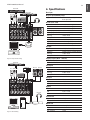
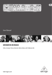
5. Applications
UL2000M
MP3 Player
Fig.5.2: Live Small Combo
HPS5000
XENYX1002B
UCA222
Fig.5.1: Field Recording
B212A
B212A
9
6. Specifications
DSP2024P
DSP2024P
Mono inputs
B-1 XM1800S
Microphone inputs (XENYX Mic preamp)
Type
XLR connector, electronically balanced,
discrete input circuit
HPS5000
B2031A
B2031A
XENYX1002B
Mic E.I.N.1 (20 Hz - 20 kHz)
@ 0 Ω source resistance
@ 50 Ω source resistance
@ 150 Ω source resistance
Frequency response (–1 dB)
Frequency response (–3 dB)
Gain range
Max. input level
Impedance
Signal-to-noise ratio
Distortion (THD+N)
Line input
UCA222
Type
Impedance
Gain range
Max. input level
Fig.5.3: Computer Recording
¼" TRS jack, electronically balanced
20 k Ohms balanced, 10 k Ohms unbalanced
-10 dB to +40 dB
+22 dBu @ 0 dB GAIN
Frequency response (Mic In → Main Out)
<10 Hz - 90 kHz (-1 dB)
<10 Hz - 160 kHz (-3 dB)
DSP2024P
DV Deck
B-1 XM1800S
-134 dB 135.7 dB A-weighted
-131 dB 133.3 dB A-weighted
-129 dB 130.5 dB A-weighted
<10 Hz - 160 kHz (-1 dB)
<10 Hz - 200 kHz (-3 dB)
+14 dB to +60 dB
+12 dBu @ +10 dB GAIN
2.6 k Ohms balanced
120 dB A-weighted (0 dBu In @ +22 dB GAIN)
0.005% / 0.004% A-weighted
+0 dB / -1 dB
+0 dB / -3 dB
Stereo inputs
B2031A
B2031A
Type
Impedance
Gain range
Max. input level
2 x ¼" TRS jack, balanced
20 k Ohms balanced, 10 k Ohms unbalanced
-20 dB to +20 dB
+22 dBu @ 0 dB GAIN
CD/Tape In
Type
Impedance
Max. input level
RCA connector
10 k Ohms
+22 dBu
Equalizer
HPS5000
XENYX1002B
LOW
MID
HIGH
Channel inserts
Type
Max. input level
FCA202
Fig.5.4: Video Editing
50 Hz / +- 15 dB
700 Hz / +- 15 dB
10 kHz / +- 15 dB
¼" TRS jack, unbalanced
+22 dBu
MON/FX send
Type
Impedance
Max. output level
¼" mono jack, unbalanced
120 Ohms
+22 dBu
ENGLISH
XENYX 1002B User Manual
XENYX 1002B User Manual
ENGLISH
10
Main outputs
Type
Impedance
Max. output level
¼" TRS jack, electronically balanced
240 Ohms balanced, 120 Ohms balanced
+28 dBu
Phones output
Type
Max. output level
¼" TRS jack, unbalanced
+19 dBu / 150 Ohms (+25 dBm)
CD/Tape out
Type
Impedance
Max. output level
RCA connector
1 k Ohms
+22 dBu
Main mix system data (Noise)3
Main mix @ -∞,
channel fader @ -∞
Main mix @ 0 dB,
channel fader @ -∞
Main mix @ 0 dB,
channel fader @ 0 dB
-100 dB / -102.5 dB A weighted
-82 dB / -85 dB A weighted
-72 dB / -75 dB A weighted
Power supply
Power consumption
Fuse (100 - 120 V~, 50/60 Hz)
Fuse (220 - 230 V~, 50/60 Hz)
Mains connector
50 W
T 2,0 A H 250 V
T 2,0 A H 250 V
Standard IEC receptacle
Phantom power
With battery power
With AC adaptor
+18V
+23V
Battery
Battery life
4 hours w/ high quality Alkaline battery
Physical/weight
Dimensions (H x W x D)
Weight 1 9/16" (40 mm) / 2 7/8" (73 mm) x 11 3/4"
(298 mm) x 8 1/2" (216 mm)
5.5 lbs / 2.5 kg (PSU not included)
11
Limited waranty
§ 1 Warranty
[2] This limited warranty does not cover the product if it has been electronically or
[1]�This limited warranty is valid only if you purchased the product from a BEHRINGER
mechanically modified in any way. If the product needs to be modified or adapted in
order to comply with applicable technical or safety standards on a national or local
level, in any country which is not the country for which the product was originally
developed and manufactured, this modification/adaptation shall not be considered
a defect in materials or workmanship. This limited warranty does not cover any such
modification/adaptation, regardless of whether it was carried out properly or not.
Under the terms of this limited warranty, BEHRINGER shall not be held responsible for
any cost resulting from such a modification/adaptation.
authorized dealer in the country of purchase. A list of authorized dealers can be found
on BEHRINGER’s website www.behringer.com under “Where to Buy”, or you can contact
the BEHRINGER office closest to you.
[2] BEHRINGER* warrants the mechanical and electronic components of this product
to be free of defects in material and workmanship if used under normal operating
conditions for a period of one (1) year from the original date of purchase (see the
Limited Warranty terms in § 4 below), unless a longer minimum warranty period
is mandated by applicable local laws. If the product shows any defects within the
specified warranty period and that defect is not excluded under § 4, BEHRINGER
shall, at its discretion, either replace or repair the product using suitable new or
reconditioned product or parts. In case BEHRINGER decides to replace the entire
product, this limited warranty shall apply to the replacement product for the remaining
initial warranty period, i.e., one (1) year (or otherwise applicable minimum warranty
period) from the date of purchase of the original product.
[3] Upon validation of the warranty claim, the repaired or replacement product will
be returned to the user freight prepaid by BEHRINGER.
[4] Warranty claims other than those indicated above are expressly excluded.
PLEASE RETAIN YOUR SALES RECEIPT. IT IS YOUR PROOF OF PURCHASE COVERING
YOUR LIMITED WARRANTY. THIS LIMITED WARRANTY IS VOID WITHOUT SUCH PROOF
OF PURCHASE.
§ 2 Online registration
Please do remember to register your new BEHRINGER equipment right after your
purchase at www.behringer.com under “Support” and kindly read the terms and
conditions of our limited warranty carefully. Registering your purchase and equipment
with us helps us process your repair claims quicker and more efficiently. Thank you for
your cooperation!
§ 3 Return authorization number
[1]�To obtain warranty service, please contact the retailer from whom the equipment
was purchased. Should your BEHRINGER dealer not be located in your vicinity, you
may contact the BEHRINGER distributor for your country listed under “Support” at
www.behringer.com. If your country is not listed, please check if your problem can
be dealt with by our “Online Support” which may also be found under “Support”
at www.behringer.com. Alternatively, please submit an online warranty claim at
www.behringer.com BEFORE returning the product. All inquiries must be accompanied
by a description of the problem and the serial number of the product. After verifying
the product’s warranty eligibility with the original sales receipt, BEHRINGER will then
issue a Return Materials Authorization (“RMA”) number.
[3] This limited warranty covers only the product hardware. It does not cover
technical assistance for hardware or software usage and it does not cover any software
products whether or not contained in the product. Any such software is provided “AS IS”
unless expressly provided for in any enclosed software limited warranty.
[4] This limited warranty is invalid if the factory-applied serial number has been
altered or removed from the product.
[5] Free inspections and maintenance/repair work are expressly excluded from this
limited warranty, in particular, if caused by improper handling of the product by the
user. This also applies to defects caused by normal wear and tear, in particular, of
faders, crossfaders, potentiometers, keys/buttons, tubes, guitar strings, illuminants and
similar parts.
[6] Damage/defects caused by the following conditions are not covered by this
limited warranty:
• improper handling, neglect or failure to operate the unit in compliance with
the instructions given in BEHRINGER user or service manuals;
• connection or operation of the unit in any way that does not comply with the
technical or safety regulations applicable in the country where the product
is used;
• damage/defects caused by acts of God/Nature (accident, fire, flood, etc) or any
other condition that is beyond the control of BEHRINGER.
[7] Any repair or opening of the unit carried out by unauthorized personnel
(user included) will void the limited warranty.
[8] If an inspection of the product by BEHRINGER shows that the defect in question is
not covered by the limited warranty, the inspection costs are payable by the customer.
[9] Products which do not meet the terms of this limited warranty will be repaired
exclusively at the buyer’s expense. BEHRINGER or its authorized service center will
inform the buyer of any such circumstance. If the buyer fails to submit a written repair
order within 6 weeks after notification, BEHRINGER will return the unit C.O.D. with a
separate invoice for freight and packing. Such costs will also be invoiced separately
when the buyer has sent in a written repair order.
[10] Authorized BEHRINGER dealers do not sell new products directly in online
[3] Shipments without freight prepaid will not be accepted.
auctions. Purchases made through an online auction are on a “buyer beware”
basis. Online auction confirmations or sales receipts are not accepted for warranty
verification and BEHRINGER will not repair or replace any product purchased through
an online auction.
§ 4 Warranty Exclusions
§ 5 Warranty transferability
[1]�This limited warranty does not cover consumable parts including, but not limited
This limited warranty is extended exclusively to the original buyer (customer of
authorized retail dealer) and is not transferable to anyone who may subsequently
purchase this product. No other person (retail dealer, etc.) shall be entitled to give any
warranty promise on behalf of BEHRINGER.
[2] Subsequently, the product must be returned in its original shipping carton,
together with the return authorization number to the address indicated by BEHRINGER.
to, fuses and batteries. Where applicable, BEHRINGER warrants the valves or meters
contained in the product to be free from defects in material and workmanship for a
period of ninety (90) days from date of purchase.
ENGLISH
XENYX 1002B User Manual
EN
XENYX 1002B User Manual
ENGLISH
12
Legal Disclaimer
§ 6 Claim for damage
Subject only to the operation of mandatory applicable local laws, BEHRINGER shall
have no liability to the buyer under this warranty for any consequential or indirect loss
or damage of any kind. In no event shall the liability of BEHRINGER under this limited
warranty exceed the invoiced value of the product.
§ 7 Limitation of liability
This limited warranty is the complete and exclusive warranty between you and
BEHRINGER. It supersedes all other written or oral communications related to this
product. BEHRINGER provides no other warranties for this product.
§ 8 Other warranty rights and national law
[1]�This limited warranty does not exclude or limit the buyer’s statutory rights as a
consumer in any way.
[2] The limited warranty regulations mentioned herein are applicable unless they
constitute an infringement of applicable mandatory local laws.
[3] This warranty does not detract from the seller’s obligations in regard to any lack of
conformity of the product and any hidden defect.
§ 9 Amendment
Warranty service conditions are subject to change without notice. For the latest
warranty terms and conditions and additional information regarding BEHRINGER’s
limited warranty, please see complete details online at www.behringer.com.
* BEHRINGER Macao Commercial Offshore Limited of Rue de Pequim No. 202-A, Macau Finance Centre 9/J,
Macau, including all BEHRINGER group companies
Technical specifications and appearance are subject to change without
notice. The information contained herein is correct at the time of printing.
BEHRINGER accepts no liability for any loss which may be suffered by any
person who relies either wholly or in part upon any description, photograph
or statement contained herein. Colors and specifications may vary slightly
from product. BEHRINGER products are sold through authorized dealers
only. Distributors and dealers are not agents of BEHRINGER and have
absolutely no authority to bind BEHRINGER by any express or implied
undertaking or representation. This manual is copyrighted. No part of
this manual may be reproduced or transmitted in any form or by any
means, electronic or mechanical, including photocopying and recording
of any kind, for any purpose, without the express written permission of
Red Chip Company Ltd.
ALL RIGHTS RESERVED. © 2009 Red Chip Company Ltd.
Trident Chambers, Wickhams Cay, P.O. Box 146,
Road Town, Tortola, British Virgin Islands
FEDERAL COMMUNICATIONS
COMMISSION COMPLIANCE
INFORMATION
XENYX 1002B
Responsible party name: BEHRINGER USA, Inc.
Address:
18912 North Creek Parkway,
Suite 200 Bothell, WA 98011,
USA
Phone/Fax No.:
Phone: +1 425 672 0816
Fax: +1 425 673 7647
hereby declares that the product
XENYX 1002B
complies with the FCC rules as mentioned in the following
paragraph:
This equipment has been tested and found to comply
with the limits for a Class B digital device, pursuant to part
15 of the FCC Rules. These limits are designed to provide
reasonable protection against harmful interference in a
residential installation. This equipment generates, uses
and can radiate radio frequency energy and, if not installed
and used in accordance with the instructions, may cause
harmful interference to radio communications. However,
there is no guarantee that interference will not occur in a
particular installation. If this equipment does cause harmful
interference to radio or television reception, which can be
determined by turning the equipment off and on, the user is
encouraged to try to correct the interference by one or more
of the following measures:
• Reorient or relocate the receiving antenna.
• Increase the separation between the equipment and
receiver.
• Connect the equipment into an outlet on a circuit different
from that to which the receiver is connected.
• Consult the dealer or an experienced radio/TV technician
for help.
13
This device complies with Part 15 of the FCC rules. Operation
is subject to the following two conditions:
(1) this device may not cause harmful interference, and
(2) this device must accept any interference received,
including interference that may cause undesired operation.
Important information:
Changes or modifications to the equipment not expressly
approved by BEHRINGER USA can void the user’s authority
to use the equipment.
ENGLISH
XENYX 1002B User Manual
ENGLISH
This manual is available in English, German, Spanish and
Chinese. Download them by going to the appropriate product
page at:
www.behringer.com