1
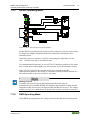
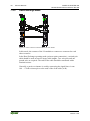
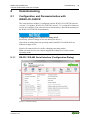
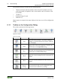
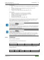
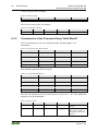
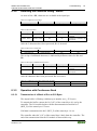
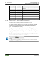
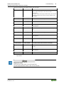
Manual
WAGO-I/O-SYSTEM 750
Serial Interface RS-232 / RS-485
750-652
Configurable
Version 1.3.0
2
WAGO-I/O-SYSTEM 750
750-652 Serial Interface RS-232 / RS-485
© 2014 by WAGO Kontakttechnik GmbH & Co. KG
All rights reserved.
WAGO Kontakttechnik GmbH & Co. KG
Hansastraße 27
D-32423 Minden
Phone:
Fax:
+49 (0) 571/8 87 – 0
+49 (0) 571/8 87 – 1 69
E-Mail:
[email protected]
Web:
http://www.wago.com
Technical Support
Phone:
Fax:
+49 (0) 571/8 87 – 5 55
+49 (0) 571/8 87 – 85 55
E-Mail:
[email protected]
Every conceivable measure has been taken to ensure the accuracy and
completeness of this documentation. However, as errors can never be fully
excluded, we always appreciate any information or suggestions for improving the
documentation.
E-Mail:
[email protected]
We wish to point out that the software and hardware terms as well as the
trademarks of companies used and/or mentioned in the present manual are
generally protected by trademark or patent.
Manual
Version 1.3.0
WAGO-I/O-SYSTEM 750
750-652 Serial Interface RS-232 / RS-485
Table of Contents
3
Table of Contents
1
1.1
1.2
1.3
1.4
1.5
Notes about this Documentation ................................................................. 6
Validity of this Documentation ................................................................. 6
Copyright................................................................................................... 6
Symbols ..................................................................................................... 7
Number Notation ....................................................................................... 9
Font Conventions ...................................................................................... 9
2
Important Notes ......................................................................................... 10
2.1
Legal Bases ............................................................................................. 10
2.1.1
Subject to Changes ............................................................................. 10
2.1.2
Personnel Qualifications ..................................................................... 10
2.1.3
Use of the WAGO-I/O-SYSTEM 750 in Compliance with Underlying
Provisions ........................................................................................... 10
2.1.4
Technical Condition of Specified Devices ......................................... 11
2.2
Safety Advice (Precautions) .................................................................... 12
3
Device Description ..................................................................................... 14
3.1
View ........................................................................................................ 18
3.2
Connectors............................................................................................... 19
3.2.1
Data Contacts/Internal Bus ................................................................. 19
3.2.2
Power Jumper Contacts/Field Supply ................................................ 20
3.2.3
CAGE CLAMP® Connectors ............................................................. 22
3.3
Display Elements .................................................................................... 23
3.4
Operating Elements ................................................................................. 24
3.5
Schematic Diagram ................................................................................. 24
3.6
Technical Data ........................................................................................ 25
3.6.1
Device Data ........................................................................................ 25
3.6.2
Supply ................................................................................................. 25
3.6.3
Communication .................................................................................. 25
3.6.4
Interface .............................................................................................. 26
3.6.5
Climatic Environmental Conditions ................................................... 26
3.7
Approvals ................................................................................................ 27
3.8
Standards and Guidelines ........................................................................ 29
4
4.1
4.2
Process Image ............................................................................................. 30
Operating Modes for Serial Transmission .............................................. 30
Data Exchange Mode .............................................................................. 32
5
Function Description ................................................................................. 34
5.1
Operating Modes for Serial Transmission .............................................. 34
5.1.1
Transmit Data ..................................................................................... 34
5.1.1.1
Continuous Transmission .............................................................. 35
5.1.2
Receive Data ....................................................................................... 35
5.1.2.1
Continuous Receipt ........................................................................ 35
5.1.3
RS-232 Operating Mode..................................................................... 36
5.1.3.1
Flow Control Using XON-/XOFF Protocol .................................. 36
5.1.3.2
Flow Control Using RTS/CTS....................................................... 36
5.1.3.3
Flow Control Using RTS/CTS, RTS with Lead/Follow-on Time . 37
5.1.4
RS-485 Operating Mode..................................................................... 37
Manual
Version 1.3.0
4
Table of Contents
5.1.5
5.1.6
5.2
WAGO-I/O-SYSTEM 750
750-652 Serial Interface RS-232 / RS-485
RS-422 Operating Mode..................................................................... 37
DMX Operating Mode ....................................................................... 38
Data Exchange Operating Mode ............................................................. 38
6
Mounting..................................................................................................... 40
6.1
Mounting Sequence ................................................................................. 40
6.2
Inserting and Removing Devices ............................................................ 41
6.2.1
Inserting the I/O Module .................................................................... 41
6.2.2
Removing the I/O Module .................................................................. 42
7
Connect Devices ......................................................................................... 43
7.1
Connecting a Conductor to the CAGE CLAMP® ................................... 43
7.2
Connection Examples.............................................................................. 44
7.2.1
RS-232 Operating Mode..................................................................... 44
7.2.2
RS-485 Operating Mode..................................................................... 45
7.2.3
RS-422 Operating Mode..................................................................... 47
7.2.4
DMX Operating Mode ....................................................................... 47
7.2.5
Data Exchange Mode ......................................................................... 48
8
Commissioning ........................................................................................... 49
8.1
Configuration and Parameterization with WAGO-I/O-CHECK............. 49
8.1.1
RS-232 / RS-485 Serial Interface (Configuration Dialog) ................. 49
8.1.2
Toolbar on the Configuration Dialog ................................................. 50
8.1.3
Process Image Size ............................................................................. 51
8.1.4
Parameter Range ................................................................................. 52
8.1.5
Setting the RS-232 / RS-485 Serial Interface ..................................... 53
8.2
Configuration and Parameterization via GSD for PROFIBUS DP and
PROFINET IO ........................................................................................ 54
8.3
Data Transfer ........................................................................................... 54
8.3.1
Example of Operating Modes for Serial Transmission ...................... 54
8.3.2
Initialization........................................................................................ 55
8.3.3
Transmission of the Character String "Hello World!" ....................... 56
8.3.4
Receiving the Character String "WAGO" .......................................... 57
8.3.5
Operation with Continuous Send........................................................ 57
8.3.5.1
Transmission of a Block of One to 512 Bytes ............................... 57
8.3.5.2
Transmission of a Block of More than 512 Bytes ......................... 58
8.3.6
DMX Application Example................................................................ 60
8.3.6.1
Operation with Deactivated Continuous Send ............................... 60
8.3.6.2
Operation with Activated Continuous Send .................................. 60
8.3.7
Data Exchange Operating Mode Application Example ..................... 61
9
9.1
9.2
Diagnostics .................................................................................................. 62
Serial Operating Modes ........................................................................... 62
Data Exchange Operating Mode ............................................................. 62
10 Use in Hazardous Environments .............................................................. 63
10.1
Marking Configuration Examples ........................................................... 64
10.1.1
Marking for Europe According to ATEX and IEC-Ex ...................... 64
10.1.2
Marking for America According to NEC 500 .................................... 69
10.2
Installation Regulations ........................................................................... 70
10.2.1
Special Conditions for Safe Use (ATEX Certificate TÜV 07 ATEX
554086 X) ........................................................................................... 71
Manual
Version 1.3.0
WAGO-I/O-SYSTEM 750
750-652 Serial Interface RS-232 / RS-485
10.2.2
10.2.3
10.2.4
10.2.5
Table of Contents
5
Special Conditions for Safe Use (ATEX Certificate TÜV 12 ATEX
106032 X) ........................................................................................... 72
Special Conditions for Safe Use (IEC-Ex Certificate TUN 09.0001 X)73
Special Conditions for Safe Use (IEC-Ex Certificate IECEx TUN
12.0039 X) .......................................................................................... 74
Special Conditions for Safe Use according to ANSI/ISA 12.12.01 ... 75
11 Appendix ..................................................................................................... 76
11.1
Configuration and Parameterization via GSD for PROFIBUS DP and
PROFINET IO ........................................................................................ 76
11.1.1
Configuration of the RS-232/RS-485 Interface .................................. 76
11.1.1.1
PROFIBUS DP (750-333, 750-343, 750-833) Fieldbus Coupler
PROFINET IO (750-370) Fieldbus Coupler ................................. 76
11.1.1.2
PROFINET IO (750-375, 750-377) Fieldbus Coupler .................. 76
11.1.2
Configuration of the RS-232/RS-485 Serial Interface ....................... 77
11.1.2.1
All PROFIBUS DP and PROFINET IO Fieldbus Couplers .......... 78
11.1.2.2
PROFIBUS DP (750-333, 750-343, 750-833) Fieldbus Coupler
PROFINET IO (750-370) Fieldbus Coupler ................................. 80
11.1.2.3
PROFINET IO (750-375, 750-377) Fieldbus Coupler .................. 80
List of Figures ...................................................................................................... 81
List of Tables ........................................................................................................ 82
Manual
Version 1.3.0
6
1
Notes about this Documentation
WAGO-I/O-SYSTEM 750
750-652 Serial Interface RS-232 / RS-485
Notes about this Documentation
Always retain this documentation!
This documentation is part of the product. Therefore, retain the documentation
during the entire service life of the product. Pass on the documentation to any
subsequent user. In addition, ensure that any supplement to this documentation is
included, if necessary.
1.1
Validity of this Documentation
This documentation is only applicable to the I/O module 750-652 (Serial Interface
RS-232 / RS-485) and the variants listed in the table below.
Table 1: Variants
Item Number/Variant
750-652
750-652/025-000
Designation
Serial Interface RS-232 / RS-485
Serial Interface RS-232 / RS-485/T
Documentation Validity for Variants
Unless otherwise indicated, the information given in this documentation applies to
listed variants.
The I/O module 750-652 shall only be installed and operated according to the
instructions in this manual and in the manual for the used fieldbus
coupler/controller.
Consider power layout of the WAGO-I/O-SYSTEM 750!
In addition to these operating instructions, you will also need the manual for the
used fieldbus coupler/controller, which can be downloaded at www.wago.com.
There, you can obtain important information including information on electrical
isolation, system power and supply specifications.
1.2
Copyright
This Manual, including all figures and illustrations, is copyright-protected. Any
further use of this Manual by third parties that violate pertinent copyright
provisions is prohibited. Reproduction, translation, electronic and phototechnical
filing/archiving (e.g., photocopying) as well as any amendments require the
written consent of WAGO Kontakttechnik GmbH & Co. KG, Minden, Germany.
Non-observance will involve the right to assert damage claims.
Manual
Version 1.3.0
WAGO-I/O-SYSTEM 750
750-652 Serial Interface RS-232 / RS-485
1.3
Notes about this Documentation
7
Symbols
Personal Injury!
Indicates a high-risk, imminently hazardous situation which, if not avoided, will
result in death or serious injury.
Personal Injury Caused by Electric Current!
Indicates a high-risk, imminently hazardous situation which, if not avoided, will
result in death or serious injury.
Personal Injury!
Indicates a moderate-risk, potentially hazardous situation which, if not avoided,
could result in death or serious injury.
Personal Injury!
Indicates a low-risk, potentially hazardous situation which, if not avoided, may
result in minor or moderate injury.
Damage to Property!
Indicates a potentially hazardous situation which, if not avoided, may result in
damage to property.
Damage to Property Caused by Electrostatic Discharge (ESD)!
Indicates a potentially hazardous situation which, if not avoided, may result in
damage to property.
Important Note!
Indicates a potential malfunction which, if not avoided, however, will not result in
damage to property.
Manual
Version 1.3.0
8
Notes about this Documentation
WAGO-I/O-SYSTEM 750
750-652 Serial Interface RS-232 / RS-485
Additional Information:
Refers to additional information which is not an integral part of this
documentation (e.g., the Internet).
Manual
Version 1.3.0
WAGO-I/O-SYSTEM 750
750-652 Serial Interface RS-232 / RS-485
1.4
Notes about this Documentation
9
Number Notation
Table 2: Number Notation
Number Code
Decimal
Hexadecimal
Binary
1.5
Example
100
0x64
'100'
'0110.0100'
Note
Normal notation
C notation
In quotation marks, nibble separated with
dots (.)
Font Conventions
Table 3: Font Conventions
Font Type Indicates
italic
Names of paths and data files are marked in italic-type.
e.g.: C:\Programme\WAGO-I/O-CHECK
Menu items are marked in bold letters.
Menu
e.g.: Save
A greater-than sign between two names means the selection of a
>
menu item from a menu.
e.g.: File > New
Designation of input or optional fields are marked in bold letters,
Input
e.g.: Start of measurement range
“Value”
Input or selective values are marked in inverted commas.
e.g.: Enter the value “4 mA” under Start of measurement range.
Pushbuttons in dialog boxes are marked with bold letters in square
[Button]
brackets.
e.g.: [Input]
Keys are marked with bold letters in square brackets.
[Key]
e.g.: [F5]
Manual
Version 1.3.0
10
Important Notes
2
WAGO-I/O-SYSTEM 750
750-652 Serial Interface RS-232 / RS-485
Important Notes
This section includes an overall summary of the most important safety
requirements and notes that are mentioned in each individual section. To protect
your health and prevent damage to devices as well, it is imperative to read and
carefully follow the safety guidelines.
2.1
Legal Bases
2.1.1
Subject to Changes
WAGO Kontakttechnik GmbH & Co. KG reserves the right to provide for any
alterations or modifications that serve to increase the efficiency of technical
progress. WAGO Kontakttechnik GmbH & Co. KG owns all rights arising from
the granting of patents or from the legal protection of utility patents. Third-party
products are always mentioned without any reference to patent rights. Thus, the
existence of such rights cannot be excluded.
2.1.2
Personnel Qualifications
All sequences implemented on WAGO-I/O-SYSTEM 750 devices may only be
carried out by electrical specialists with sufficient knowledge in automation. The
specialists must be familiar with the current norms and guidelines for the devices
and automated environments.
All changes to the coupler or controller should always be carried out by qualified
personnel with sufficient skills in PLC programming.
2.1.3
Use of the WAGO-I/O-SYSTEM 750 in Compliance with
Underlying Provisions
Fieldbus couplers, fieldbus controllers and I/O modules found in the modular
WAGO-I/O-SYSTEM 750 receive digital and analog signals from sensors and
transmit them to actuators or higher-level control systems. Using programmable
controllers, the signals can also be (pre-) processed.
The devices have been developed for use in an environment that meets the IP20
protection class criteria. Protection against finger injury and solid impurities up to
12.5 mm diameter is assured; protection against water damage is not ensured.
Unless otherwise specified, operation of the devices in wet and dusty
environments is prohibited.
Operating the WAGO-I/O-SYSTEM 750 devices in home applications without
further measures is only permitted if they meet the emission limits (emissions of
interference) according to EN 61000-6-3. You will find the relevant information
in the section “Device Description” > “Standards and Guidelines” in the manual
for the used fieldbus coupler/controller.
Manual
Version 1.3.0
WAGO-I/O-SYSTEM 750
750-652 Serial Interface RS-232 / RS-485
Important Notes
11
Appropriate housing (per 94/9/EG) is required when operating the WAGO-I/OSYSTEM 750 in hazardous environments. Please note that a prototype test
certificate must be obtained that confirms the correct installation of the system in
a housing or switch cabinet.
2.1.4
Technical Condition of Specified Devices
The devices to be supplied ex works are equipped with hardware and software
configurations, which meet the individual application requirements. WAGO
Kontakttechnik GmbH & Co. KG will be exempted from any liability in case of
changes in hardware or software as well as to non-compliant usage of devices.
Please send your request for modified and new hardware or software
configurations directly to WAGO Kontakttechnik GmbH & Co. KG.
Manual
Version 1.3.0
12
2.2
Important Notes
WAGO-I/O-SYSTEM 750
750-652 Serial Interface RS-232 / RS-485
Safety Advice (Precautions)
For installing and operating purposes of the relevant device to your system the
following safety precautions shall be observed:
Do not work on devices while energized!
All power sources to the device shall be switched off prior to performing any
installation, repair or maintenance work.
Install the device only in appropriate housings, cabinets or in electrical
operation rooms!
The WAGO-I/O-SYSTEM 750 and its components are an open system. As such,
install the system and its components exclusively in appropriate housings,
cabinets or in electrical operation rooms. Allow access to such equipment and
fixtures to authorized, qualified staff only by means of specific keys or tools.
Replace defective or damaged devices!
Replace defective or damaged device/module (e.g., in the event of deformed
contacts), since the long-term functionality of device/module involved can no
longer be ensured.
Protect the components against materials having seeping and insulating
properties!
The components are not resistant to materials having seeping and insulating
properties such as: aerosols, silicones and triglycerides (found in some hand
creams). If you cannot exclude that such materials will appear in the component
environment, then install the components in an enclosure being resistant to the
above-mentioned materials. Clean tools and materials are imperative for handling
devices/modules.
Clean only with permitted materials!
Clean soiled contacts using oil-free compressed air or with ethyl alcohol and
leather cloths.
Manual
Version 1.3.0
WAGO-I/O-SYSTEM 750
750-652 Serial Interface RS-232 / RS-485
Important Notes
13
Do not use any contact spray!
Do not use any contact spray. The spray may impair contact area functionality in
connection with contamination.
Do not reverse the polarity of connection lines!
Avoid reverse polarity of data and power supply lines, as this may damage the
devices involved.
Avoid electrostatic discharge!
The devices are equipped with electronic components that may be destroyed by
electrostatic discharge when touched. Please observe the safety precautions
against electrostatic discharge per DIN EN 61340-5-1/-3. When handling the
devices, please ensure that environmental factors (personnel, work space and
packaging) are properly grounded.
Manual
Version 1.3.0
14
3
Device Description
WAGO-I/O-SYSTEM 750
750-652 Serial Interface RS-232 / RS-485
Device Description
The I/O module 750-652 (Serial Interface RS-232 / RS-485) allows the optional
connection of devices with a RS-485, RS-422 or RS-232 interface.
It also provides gateways between the serial interface and the fieldbus systems
supported by the WAGO-I/O-SYSTEM 750.
No higher protocol level is required by the module. Communication to the
associated fieldbus master is completely transparent. This provides for a broader
application scope for the serial interface module. If required, communication
protocols can be configured via fieldbus master.
The 2560 byte input buffer provides for high data baud rates. At lower baud rates,
the data received in lower priority tasks is evaluated without data loss.
The 512-byte output buffer provides fast transmission of larger data strings.
The operating mode of the I/O module can be configured with the start-up tool
WAGO-I/O-CHECK 3.3 (firmware version 03 or higher requires WAGO-I/OCHECK version 3.5.3 or higher).
NOTE
The default operating mode is RS-485 half-duplex. The default data transmission
rate is 9600 baud. 1 start bit, 8 data bits and 1 stop bit are sent. There is no parity
generation and dataflow control.
Before starting operation, the connections of the I/O module must be cabled
appropriately (see section “Connect Devices” > … > “Connection Examples” ).
In RS-232 mode, the interface works in accordance with the TIA/EIA-232-F and
CCITT V.28/DIN 66259-1 standards.
In RS-485/RS-422 mode, the interface works in accordance with the TIA/EIA485-A, DIN 66259 standards.
The connected device can communicate directly with the control unit via the
fieldbus coupler/controller used.
The active communication channel works independent of the fieldbus system used
in full or half-duplex operation at up to 115200 baud.
In the data flow control through RTS/CTS in RS-232 mode, a lead time or followon time can be configured for the I/O module for the RTS signal. This function is
available with firmware version 03 or higher.
Direct data exchange between different fieldbus nodes of the 750 series is possible
in conjunction with a second I/O module. This function is available with firmware
version 03 or higher.
Manual
Version 1.3.0
WAGO-I/O-SYSTEM 750
750-652 Serial Interface RS-232 / RS-485
Device Description
15
The I/O module can be configured as a DMX sender with a baud rate of
250 kBits/s. This function is available with firmware version 03 or higher.
The wiring to the communication partner takes place in RS-232 mode via the
TxD, RxD connections, if necessary RTS/CTS and ground and in the RS-485/
RS-422 mode via the connections A, B, X, Y, and ground.
The shield connection is fed directly to the carrier rail and contact is made
automatically by snapping the module onto the rail.
The assignment of the connections is described in the “Connectors” section.
Connection examples are shown in section “Connecting Devices” > … >
“Connection Example(s)”.
Multi-color LEDs indicate the operating status and the trouble-free internal bus
communication as well as the status of the signal transmission.
The meaning of the LEDs is described in the “Display Elements” section.
The I/O module750-652 (Serial Interface RS-232 / RS-485) receives the 24 V
voltage supply for the field level from an upstream I/O module or from the
fieldbus coupler/controller via two blade-formed power jumper contacts. It then
provides these potentials to subsequent I/O modules via two spring-formed power
jumper contacts.
The field voltage and the system voltage are electrically isolated from each other.
With consideration of the power jumper contacts, the individual modules can be
arranged in any combination when configuring the fieldbus node. An arrangement
in groups within the group of potentials is not necessary.
Manual
Version 1.3.0
16
Device Description
WAGO-I/O-SYSTEM 750
750-652 Serial Interface RS-232 / RS-485
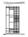
The 750-652 module can be used with the fieldbus couplers and controllers of the
WAGO-I/O-SYSTEM 750 of the specified version or higher listed in the
“Compatibility list” table.
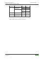
Table 4: Compatibility List 750-0652
Fieldbus
Bus System
couplers/controllers
PROFINET
Fieldbus couplers
Profibus
Fieldbus couplers
Programmable
fieldbus controller
I/O-IPC*
ETHERNET
Fieldbus couplers
Programmable
fieldbus controller
I/O-IPC
DeviceNet
CANopen
Fieldbus couplers
ECO fieldbus coupler
Programmable
fieldbus controller
Fieldbus couplers
ECO fieldbus coupler
750-370
750-333
Firmware
status
02
14
750-833
14
758-870/
000-111
758-870/
000-131
758-874/
000-111
758-875/
000-111
758-876/
000-111
750-341
750-342
750-352
750-841
750-842
750-843
750-871
750-872
750-873
750-880
750-881
750-882
758-870/
000-110
758-870/
000-130
758-874/
000-110
758-875/
000-110
758-875/
000-130
758-876/
000-110
750-306
750-346
750-806
05
750-337
750-338
750-347
750-348
19
19
08
08
Item No.
05
05
05
05
07
17
02
18
18
02
07
03
03
02
02
01
05
05
05
05
05
05
4K
10
10
Manual
Version 1.3.0
WAGO-I/O-SYSTEM 750
750-652 Serial Interface RS-232 / RS-485
Table 4: Compatibility List 750-0652
Fieldbus
Bus System
couplers/controllers
Programmable
fieldbus controller
I/O-IPC*
KNX
Device Description
Item No.
750-837
750-838
758-870/
000-112
758-875/
000-112
750-849
Programmable
fieldbus controller
BACnet
Programmable
750-830
fieldbus controller
*
Also available via 2 ETHERNET interfaces
Firmware
status
14
14
05
05
04
03
Other fieldbus couplers/controllers on request.
Manual
Version 1.3.0
17
18
3.1
Device Description
WAGO-I/O-SYSTEM 750
750-652 Serial Interface RS-232 / RS-485
View
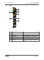
Figure 1: View
Table 5: Legend for Figure “View”
Pos. Description
1 Marking possibility with MiniWSB
2 Status LEDs
3 Data contacts
4 CAGE CLAMP® connectors
5 Power jumper contacts
6 Release tab
Details See Section
--“Device Description” > “Display Elements”
“Device Description” > “Connectors”
“Device Description” > “Connectors”
“Device Description” > “Connectors”
“Mounting” > “Inserting and Removing
Devices”
Manual
Version 1.3.0
WAGO-I/O-SYSTEM 750
750-652 Serial Interface RS-232 / RS-485
3.2
Connectors
3.2.1
Data Contacts/Internal Bus
Device Description
19
Communication between the fieldbus coupler/controller and the I/O modules as
well as the system supply of the I/O modules is carried out via the internal bus. It
is comprised of 6 data contacts, which are available as self-cleaning gold spring
contacts.
Figure 2: Data Contacts
Do not place the I/O modules on the gold spring contacts!
Do not place the I/O modules on the gold spring contacts in order to avoid soiling
or scratching!
Ensure that the environment is well grounded!
The devices are equipped with electronic components that may be destroyed by
electrostatic discharge. When handling the devices, ensure that the environment
(persons, workplace and packing) is well grounded. Avoid touching conductive
components, e.g. data contacts.
Manual
Version 1.3.0
20
Device Description
3.2.2
WAGO-I/O-SYSTEM 750
750-652 Serial Interface RS-232 / RS-485
Power Jumper Contacts/Field Supply
Risk of injury due to sharp-edged blade contacts!
The blade contacts are sharp-edged. Handle the I/O module carefully to prevent
injury.
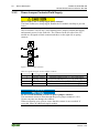
The I/O module 750-652 has 2 self-cleaning power jumper contacts that supply
and transmit power for the field side. The contacts on the left side of the I/O
module are designed as blade contacts and those on the right side as spring
contacts.
Figure 3: Power Jumper Contacts
Table 6: Legend for Figure “Power Jumper Contacts”
Contact
1
2
3
4
Type
Spring contact
Spring contact
Blade contact
Blade contact
Function
Potential transmission (Uv) for field supply
Potential transmission (0 V) for field supply
Potential feed-in (0 V) for field supply
Potential feed-in (Uv) for field supply
Do not exceed maximum current via power jumper contacts!
The maximum current to flow through the power jumper contacts is 10 A.
Greater currents can damage the contacts.
When configuring your system, ensure that this current is not exceeded. If
exceeded, insert an additional supply module.
Manual
Version 1.3.0
WAGO-I/O-SYSTEM 750
750-652 Serial Interface RS-232 / RS-485
Device Description
21
Use supply modules for ground (earth)!
The I/O module has no power jumper contacts for receiving and transmitting the
earth potential. Use a supply module when an earth potential is needed for the
subsequent I/O modules.
Manual
Version 1.3.0
22
Device Description
3.2.3
WAGO-I/O-SYSTEM 750
750-652 Serial Interface RS-232 / RS-485
CAGE CLAMP® Connectors
Use shielded signal lines!
Only use shielded signal lines for analog signals and I/O modules which are
equipped with shield clamps. Only then can you ensure that the accuracy and
interference immunity specified for the respective I/O module can be achieved
even in the presence of interference acting on the signal cable.
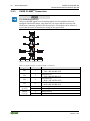
Figure 4: CAGE CLAMP® Connectors
Table 7: Legend for Figure “CAGE CLAMP® Connectors”
Designation
D0
D1
D2
D3
Common
(ground)
Shield
(screen)
Connector Function
RTS (RS-232)
1
Z / TxD+ (RS-485/RS-422)
TxD (RS-232)
5
Y / TxD- (RS-485/RS-422)
CTS (RS-232)
2
B / RxD+ (RS-485/RS-422)
RxD (RS-232)
6
A / RxD- (RS-485/RS-422)
3
Common (ground)
7
Common (ground)
4
Shield (screen)
8
Shield (screen)
Manual
Version 1.3.0
WAGO-I/O-SYSTEM 750
750-652 Serial Interface RS-232 / RS-485
3.3
Device Description
23
Display Elements
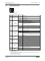
Figure 5: Display Elements
Table 8: Legend for Figure “Display Elements”
LED
Designation
Status
Green
A
Function
Red
OFF
Green
B
1)
2)
3)
4)
5)
Manual
Version 1.3.0
TxD
(transmit)
Yellow
Function
Ready for operation and undisturbed internal bus
communication
Not ready for operation or no or disturbed internal bus
communication
No signal transmission TxD
Signal transmission TxD present 1)
I/O module has received XOFF character, the
transmission is inactive 2)
CTS line has fallen, the transmission is inactive 4)
OFF
No signal transmission RxD or input open
Green
Signal transmission RxD present 1)
RxD
C
Signal transmission RxD present 1), but some characters
(receive)
Red
received are defective. (parity, data frame or overrun
error has occurred) 3)
OFF
No transmission error
Green
Output buffer is full
Transmission
Input buffer is full (LED lights up if there are more than
D
status
2304 characters in the input buffer. LED does not light
Yellow
up if there are fewer than 2176 characters in the input
buffer)
Green
RS-485 half-duplex, DMX
E
Mode
Yellow
RS-422 full-duplex, data exchange
Red
RS-232
OFF
No data flow control
Green
RTS/CTS data flow control active 4)
F
Data flow control
Yellow
XON/XOFF data flow control active 2)
Red
RTS with lead time and follow-on time is active 5)
OFF
Data exchange mode is OFF 5)
Yellow
Data exchange mode is initialized
Data exchange
G
Green
Data exchange mode is ON
mode 5)
Yellow
Data exchange mode is ON, but there is no
flashing
communication (timeout)
OFF
DMX is OFF
H
DMX 5)
Green
DMX is ON
With high baud rates, the pulses are so short that the on state cannot or can hardly be detected
with the naked eye.
XON/XOFF data flow control active
Defective characters are not transmitted by the I/O module to the fieldbus coupler/controller.
RTS/CTS data flow control active
Firmware version 03 or higher
24
3.4
Device Description
WAGO-I/O-SYSTEM 750
750-652 Serial Interface RS-232 / RS-485
Operating Elements
The I/O module 750-652 has no operating elements.
3.5
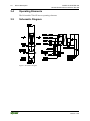
Schematic Diagram
Figure 6: Schematic Diagram
Manual
Version 1.3.0
WAGO-I/O-SYSTEM 750
750-652 Serial Interface RS-232 / RS-485
3.6
Technical Data
3.6.1
Device Data
Device Description
25
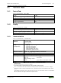
Table 9: Technical Data – Device Data
Width
Height (from upper edge of DIN 35 rail)
Length
Weight
Degree of protection
3.6.2
12 mm
64 mm
100 mm
approx. 50 g
IP20
Supply
Table 10: Technical Data – Supply
Power supply
Current consumption (internal)
Current via power jumper contacts max.
Isolation (peak value)
3.6.3
via system voltage internal bus (5 VDC)
max. 85 mA
10 A
500 V system/supply
Communication
Table 11: Technical Data – Communication
Transmission
channels
1 TxD/1 RxD, full-duplex, half-duplex,
7 or 8 bit data,
1 or 2 stop bits
Mode
• RS-232
(configurable)
• RS-485 half-duplex*)
• RS-422 full-duplex
• Data exchange RS-4221)
• DMX half-duplex/250k1)
Data flow control
RTS/CTS2) depending on mode, XON/XOFF3)
Baud rate
300 ... 115200 baud
Data width, internal 8, 24*) or 48 bytes (configurable)
Line length
RS-485/RS-422:
max. approx. 1000 m4)
RS-232:
max. 40 m
Data exchange mode/
DMX:
max. 100 m twisted pair cable
Buffer
2560 bytes for receive / 512 bytes for send5)
*)
1)
2)
3)
4)
5)
Manual
Version 1.3.0
Default setting
Possible with firmware version 03 or higher
Activation of flow control RTS/CTS is only possible for RS-232 mode
Flow control RTS/CTS with lead/follow-on time possible with firmware version 03 or higher
Activation of flow control XON/XOFF is only possible for the RS-232 and RS-422 full-duplex
mode
Depending on baud rate, bus system and cable type (use of a twisted-pair cable is recommended)
RS-232, RS-485 half-duplex, RS-422 full-duplex modes
26
Device Description
3.6.4
WAGO-I/O-SYSTEM 750
750-652 Serial Interface RS-232 / RS-485
Interface
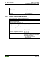
Table 12: Technical Data – Interface
Number of interfaces
Input resistance of the receiver
RS-485/RS-422
Isolation
3.6.5
1
24 kΩ (1/2 Unit Load)
Defined receiver state with shortcircuited or isolated inputs (true filesafe)
500 V system/supply
Climatic Environmental Conditions
Table 13: Technical Data – Climatic Environmental Conditions
Operating temperature range
Operating temperature range for
components with extended
temperature range (750-xxx/025-xxx)
Storage temperature range
Storage temperature range for
components with extended
temperature range (750-xxx/025-xxx)
Relative humidity
Resistance to harmful substances
Maximum pollutant concentration at
relative humidity < 75 %
Special conditions
0 °C … 55 °C
-20 °C … +60 °C
-25 °C … +85 °C
-40 °C … +85 °C
Max. 5 % … 95 % without condensation
Acc. to IEC 60068-2-42 and
IEC 60068-2-43
SO2 ≤ 25 ppm
H2S ≤ 10 ppm
Ensure that additional measures for
components are taken, which are used in
an environment involving:
– dust, caustic vapors or gases
– ionizing radiation
Manual
Version 1.3.0
WAGO-I/O-SYSTEM 750
750-652 Serial Interface RS-232 / RS-485
3.7
Device Description
27
Approvals
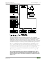
The following approvals have been granted to the basic version and all variants of
750-652 I/O modules:
Conformity Marking
CULUS
UL508
The following Ex approvals have been granted to 750-652 I/O modules:
TÜV 07 ATEX 554086 X
I M2 Ex d I Mb
II 3 G Ex nA IIC T4 Gc
II 3 D Ex tc IIIC T135°C Dc
Ambient temperature range:
0 °C ≤ Ta ≤ +60 °C
IECEx TUN 09.0001 X
Ex d I Mb
Ex nA IIC T4 Gc
Ex tc IIIC T135°C Dc
Ambient temperature range:
CULUS
0 °C ≤ Ta ≤ +60 °C
ANSI/ISA 12.12.01
Class I, Div2 ABCD T4
The following Ex approvals have been granted to the variation 750-652/025-000:
TÜV 07 ATEX 554086 X
I M2 Ex d I Mb
II 3 G Ex nA IIC T4 Gc
II 3 D Ex tc IIIC T135°C Dc
Ambient temperature range:
0 °C ≤ Ta ≤ +60 °C
IECEx TUN 09.0001 X
Ex d I Mb
Ex nA IIC T4 Gc
Ex tc IIIC T135°C Dc
Ambient temperature range:
Manual
Version 1.3.0
0 °C ≤ Ta ≤ +60 °C
28
Device Description
WAGO-I/O-SYSTEM 750
750-652 Serial Interface RS-232 / RS-485
The following ship approvals have been granted to 750-652 I/O modules:
ABS (American Bureau of Shipping)
Federal Maritime and Hydrographic Agency
BV (Bureau Veritas)
DNV (Det Norske Veritas)
Class B
GL (Germanischer Lloyd)
Cat. A, B, C, D (EMC 1)
KR (Korean Register of Shipping)
LR (Lloyd’s Register)
Env. 1, 2, 3, 4
NKK (Nippon Kaiji Kyokai)
RINA (Registro Italiano Navale)
Manual
Version 1.3.0
WAGO-I/O-SYSTEM 750
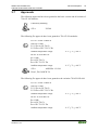
750-652 Serial Interface RS-232 / RS-485
3.8
Device Description
Standards and Guidelines
All variations of 750-652 I/O modules meet the following requirements on
emission and immunity of interference:
EMC CE-Immunity to interference
Manual
Version 1.3.0
acc. to EN 61131-2: 2007
29
30
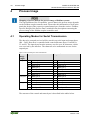
4
Process Image
WAGO-I/O-SYSTEM 750
750-652 Serial Interface RS-232 / RS-485
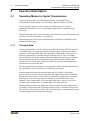
Process Image
Mapping of process data in the process image of fieldbus systems
The representation of the I/O modules’ process data in the process image depends
on the fieldbus coupler/controller used. Please take this information as well as the
particular design of the respective control/status bytes from the section “Fieldbus
Specific Design of the Process Data” included in the description concerning the
process image of the fieldbus coupler/controller used.
4.1
Operating Modes for Serial Transmission
The data to be sent and received will be stored in up to 46 input and output bytes
(D0 ... D45). Data flow is controlled with control and status bytes C0 and S0 or
C1 and S1. The input bytes form the memory area for up to 46 characters, which
were received by the interface. The characters to be transmitted are sent via the
output bytes.
Table 14: Process data for serial transmission
Process Input data
image
length
8 bytes S0 Status byte 0
S1 Status byte 1
D0 Data byte 0
D1 Data byte 1
D2 Data byte 2
…
D5 Data byte 5
24 bytes D6 Data byte 6
…
D21 Data byte 21
48 bytes D22 Data byte 22
…
D45 Data byte 45
Output data
C0
C1
D0
D1
D2
…
D5
D6
…
D21
D22
…
D45
Control byte 0
Control byte 1
Data byte 0
Data byte 1
Data byte 2
Data byte 5
Data byte 6
Data byte 21
Data byte 22
Data byte 45
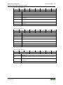
The structure of the control and status bytes is described in the tables below.
Manual
Version 1.3.0
WAGO-I/O-SYSTEM 750
750-652 Serial Interface RS-232 / RS-485
Table 15: Control Byte C0
Bit 7
Bit 6
Bit 5
RC
TR
RA
IR
SC
OL 0
OL1
OL2
RC
OL2
OL1
TA
RR
IA
IL0
IL1
IL2
BUF_F
RC
BUF_F
0
OL4
OL5
0
Manual
Version 1.3.0
Bit 4
Bit 3
Bit 2
Bit 1
Bit 0
OL0
SC
IR
RA
TR
Bit 5
Bit 4
Bit 3
Bit 2
Bit 1
Bit 0
IL2
IL1
IL0
IA
RR
TA
Transmit acknowledge
Receive request
Initialization acknowledge
Input length (number of characters received that are available in the input data,
bit 0)
Input length (number of characters received that are available in the input data,
bit 1)
Input length (number of characters received that are available in the input data,
bit 2)
Buffer full (message: input buffer is full)
Reserved for internal communication
Table 17: Control Byte C1
Bit 7
Bit 6
Bit 5
OL3
31
Transmit request
Receive acknowledge
Initialization request
Send continuous (of data from the FIFO)
Output length (number of characters to be sent that were stored in the output
data, bit 0)
Output length (number of characters to be sent that were stored in the output
data, bit 1)
Output length (number of characters to be sent that were stored in the output
data, bit 2)
Reserved for internal communication
Table 16: Status Byte S0
Bit 7
Bit 6
RC
Process Image
0
Bit 4
Bit 3
0
Bit 2
Bit 1
Bit 0
OL5
OL4
OL3
Output length (number of characters to be sent that were stored in the output
data, bit 3)
Output length (number of characters to be sent that were stored in the output
data, bit 4)
Output length (number of characters to be sent that were stored in the output
data, bit 5)
This constant must be set to 0.
32
Process Image
WAGO-I/O-SYSTEM 750
750-652 Serial Interface RS-232 / RS-485
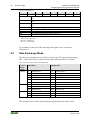
Table 18: Status Byte S1
Bit 7
Bit 6
EOV
EFR
Bit 5
Bit 4
Bit 3
Bit 2
Bit 1
Bit 0
EPR
CTS
BUF_E
IL5
IL4
IL3
IL3
Input length (number of characters received that are available in the input data,
bit 3)
IL4
Input length (number of characters received that are available in the input data,
bit 4)
IL5
Input length (number of characters received that are available in the input data,
bit 5)
BUF_E
Buffer empty (message: transmit inactive)
CTS
This value is always 01).
EPR
Error parity (message: error during the parity check)
EFR
Error framing (message: data frame is defective)
EOV
Error overrun (message: a character was lost during receipt)
1)
Only applies to flow control "RTS with lead/follow-on time":
Status of the CTS input:
Bit 4 is 0: CTS active
Bit 4 is 1: CTS inactive
For evaluation of the bits of the status byte that signal errors, see chapter
"Diagnostics".
4.2
Data Exchange Mode
The data to be sent and received will be stored in up to 47 input and output bytes
(D0 ... D46). Data flow is controlled with control and status bytes C0 and S0.
Table 19: Process Data in Data Exchange Mode
Process Input data
image
length
8 bytes S0 Status byte 0
D0 Data byte 0
D1 Data byte 1
D2 Data byte 2
…
D6 Data byte 6
24 bytes D7 Data byte 7
…
D22 Data byte 22
48 bytes D23 Data byte 23
…
D46 Data byte 46
Output data
C0
D0
D1
D2
…
D6
D7
…
D22
D23
…
D46
Control byte 0
Data byte 0
Data byte 1
Data byte 2
Data byte 6
Data byte 7
Data byte 22
Data byte 23
Data byte 46
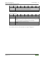
The structure of the control and status bytes is described in the tables below.
Manual
Version 1.3.0
WAGO-I/O-SYSTEM 750
750-652 Serial Interface RS-232 / RS-485
Table 20: Control Byte C0
Bit 7
Bit 6
Bit 5
RC
IR
X
Table 21: Status Byte S0
Bit 7
Bit 6
RC
LGT
CHK
RCVT
Bit 4
Bit 3
Bit 2
Bit 1
Bit 0
X
X
IR
X
X
X
Bit 5
Bit 4
Bit 3
Bit 2
Bit 1
Bit 0
X
X
RCVT
CHK
0
LGT
The length of the telegram last received does not match the PI size.
Wrong checksum received.
No error-free transmission of the opposite side was received for >= 200 ms
(timeout).
After the timeout has elapsed, an attempt is made to reestablish communication
between the I/O modules. If a valid telegram is received from the
communication partner, the RCVT bit is reset.
Not used
This value is always 0.
Reserved for internal communication
For evaluation of the bits of the status byte, see chapter "Diagnostics".
Manual
Version 1.3.0
33
Initialization/reset (If the bit is set, the module is in the reset state.
Communication is started only after resetting the bit).
Reserved for internal communication
Not used
RC
X
X
0
RC
X
Process Image
34
Function Description
WAGO-I/O-SYSTEM 750
750-652 Serial Interface RS-232 / RS-485
5
Function Description
5.1
Operating Modes for Serial Transmission
In den
In the operating modes for serial transmission, the I/O module allows
communication with serial devices via RS-232, RS-485, RS-422 or DMX.
The I/O module operates in these modes as a link between one of these
standardized interfaces to the one side and the application or controller to the
other side.
Data transmission between the I/O module and serial devices is determined by the
respective interface parameters, e.g. baud rate.
Data transmission between the application and I/O module is controlled by the
control and status bytes.
5.1.1
Transmit Data
If data is transmitted via the I/O module to an RS-232, RS-485, RS-422 interface
or in DMX mode, the application writes to the data bytes of the process image
(output) per each part of the data. The application modifies the control bytes, so
that they signal to the I/O module that new data has arrived. The I/O module
receives the data sent to the output buffer and modifies the status bytes. Based on
these modified status bytes, the application can again recognize that the data
transfer was successful. Only when this feedback is present can the application
transmit the next part of the data.
The data transmission rates between the application and I/O module and between
the I/O module and serial interface are normally not identical.
If data transmission between the application and I/O module is faster than
between the I/O module and serial interface, the output buffer in the I/O module
fills up faster than it clears. If the application transmits continuously, the output
buffer queue even rises when data is continuously transmitted on the serial
interface. If the output buffer is full, the application has to wait for space to be
available in the output buffer by transmitting to the serial interface.
If data transmission between application and I/O module is slower than between
I/O module and serial interface, the output buffer in the I/O module fills up faster
than it clears. Transmission of data on the serial interface is repeatedly interrupted
even if the application continuously transmits.
Manual
Version 1.3.0
WAGO-I/O-SYSTEM 750
750-652 Serial Interface RS-232 / RS-485
5.1.1.1
Function Description
35
Continuous Transmission
The I/O module can be set either to transmit data in the output buffer to the serial
interface immediately or to start the transmission process only after released by
the application. The latter is useful when data has to be transmitted on the serial
interface according to time criteria, but data transmission between the application
and I/O module is slower than between the I/O module and serial interface.
If continuous transmission is activated, the I/O module evaluates the bit SC in
control byte 0. Only when SC takes the value 1 does the I/O module transmit the
data contained in the output buffer to the serial interface. The application can set
SC to 0 to prompt the I/O module to accumulate data in the output buffer.
5.1.2
Receive Data
If the I/O module receives data via an RS-232, RS-485 or RS-422 interface, the
data is written to the input buffer of the I/O module. The I/O module transfers data
to the application consecutively long as there is data in the input buffer. The I/O
module writes the respective part of the data to the data bytes of the process
image. The I/O module modifies the status bytes. Based on these modified status
bytes, the application can recognize that new data has been received, which it can
then evaluate. The application modifies the control bytes, so that they signal to the
I/O module that the data transfer was successful. Only when this feedback is
present can the I/O module transmit the next part of the data received.
5.1.2.1
Continuous Receipt
If there is data in the input buffer, the I/O module can be set either to begin
transmitting data to the application immediately or to wait to receive additional
data.
If the I/O module begins to transmit data to the application immediately, only part
of a contiguous message may have been received by that point. Whether a
message has been transmitted on the serial interface according to time criteria is
then no longer evident for the application.
Example: A serial device transmits 20 bytes. After the I/O module has received
1 byte, it begins to transmit the date to the application. The I/O module transmits
the remaining 19 bytes received in the meantime only after the application has
confirmed receipt of the first byte.
If continuous receipt is activated, the I/O module begins transmitting data to the
application only if no additional data has been received on the serial interface for
a specific period of time. In the example above, the I/O module would only start
transmitting data to the application when all 20 bytes have been received.
Manual
Version 1.3.0
36
Function Description
WAGO-I/O-SYSTEM 750
750-652 Serial Interface RS-232 / RS-485
The time period after which the I/O module starts data transmission can be
defined using the "Continuous Receive Timeout" parameter. Because the duration
of the transfer of any amount of data depends on the baud rate setting, number of
data and stop bits and the parity, an absolute time specification is not feasible.
Therefore, the time required to transmit exactly one character to the serial
interface in the current interface parameter setting is used as the unit of
measurement.
5.1.3
RS-232 Operating Mode
The RS-232 operating mode in full-duplex is realized in a 2-wire or 4-wire pointto-point connection. Simultaneous transmission and receiving is possible.
In this mode, the I/O module supports flow control for the serial interface. The I/O
module can be set, so that flow control occurs using of one of the following
methods:
•
•
•
5.1.3.1
XON-/XOFF protocol
RTS/CTS
RTS/CTS, RTS with lead / follow-on time (firmware version 03 or higher)
Flow Control Using XON-/XOFF Protocol
If flow control is activated using XON-/XOFF protocol, the I/O modules stops
transmitting data to the serial interface when it receives the XOFF character
(DC3==0x13) from the serial device. The I/O module continues transmitting data
when it receives the XON character (DC1==0x11). When data is received, the I/O
module monitors input buffer usage. It transmits the XOFF control character to
the serial device when the number of characters in the input buffer exceeds 2304.
If the number of characters in the input buffer is below 2176, it transmits XON.
5.1.3.2
Flow Control Using RTS/CTS
If flow control is activated using RTS/CTS, the I/O module stops transmitting
data to the serial interface when CTS is set. The I/O module continues
transmitting data when CTS is reset. When data is received, the I/O module
monitors input buffer usage. It sets RTS when the number of characters in the
input buffer exceeds 2304. If the number of characters in the input buffer is below
2176, the I/O module resets RTS.
Manual
Version 1.3.0
WAGO-I/O-SYSTEM 750
750-652 Serial Interface RS-232 / RS-485
5.1.3.3
Function Description
37
Flow Control Using RTS/CTS, RTS with Lead/Follow-on Time
With firmware version 03 or higher, the I/O module allows RTS/CTS for
communication with serial devices that only support a half-duplex connection.
This is important, for example, for communication with some telecontrol
modems.
If this type of flow control is activated, the I/O module sets RTS while it transmits
data to the serial interface. This allows the serial device to switch between receive
and transmit depending on RTS. Depending on the technology of the serial
device, the switch can take some time. Therefore, the I/O module can be
configured to set RTS already some time before transmission of the first character
(RTS lead time) or RTS resets only some time after transmission of the last
character (RTS follow-on time).
The RTS lead time and RTS follow-on time can be configured independent of
each other within the valid rage of 0 to 1000 ms.
If RTS is activated with lead time, the current state of the CTS input is
represented by the CTS bit changing in status byte 1.
5.1.4
RS-485 Operating Mode
The RS-485 operating mode in half-duplex is realized in a 2-wire multi-endpoint
(bus) connection. Simultaneous transmission and receiving is not possible with
2-wire connections. The I/O module switches to receive mode after transmitting
the content of the input buffer to the serial interface completely.
The the "RS-485 switching time" parameter can be used to configure the time
frame when the I/O module should switch after transmitting the last character can
be configured.
Possible settings are:
•
100 µs (default setting)
•
Duration of the transfer of two characters with the current configuration
•
Duration of the transfer of four characters at the current configuration
5.1.5
RS-422 Operating Mode
The RS-422 operating mode in full-duplex is realized in a 4-wire point-to-point
connection. Simultaneous transmission and receiving is thus possible.
In this mode, the I/O module supports flow control for the serial interface using
the XON/XOFF protocol (see chapter "Flow Control Using XON-/XOFF
Protocol").
Manual
Version 1.3.0
38
Function Description
5.1.6
WAGO-I/O-SYSTEM 750
750-652 Serial Interface RS-232 / RS-485
DMX Operating Mode
The DMX operating mode is also available with firmware version 03 or higher.
In this mode, the I/O module functions as a DMX sender and allows up to 31
nodes to be connected.
The transmission channel is based on RS-485 physics with a transmission rate of
250 kBaud, as well as 1 start and 2 stop bits. In this mode, no further settings are
possible.
The structure of the transmitted telegram corresponds to the DMX 512/1990 (DIN
96530-2) specification.
The I/O module can transmit up to 255 bytes of data in this mode. Every
transmission of a DMX telegram begins with the transmission of the DMX start
byte. DMX channels 1 to 254 can be operated.
The possible refresh rate of DMX data depends on the number of channels
operated. By limiting the maximum channel number to 5, 21 or 45 (at a set
process image size of the I/O module of 8, 24 or 48 bytes), refresh rates of up to
200, 125 or 80 Hz are possible (see chapter "DMX Application Example").
5.2
Data Exchange Operating Mode
The Data Exchange operating mode is also available with firmware version 03 or
higher.
In this mode, the I/O module allows cyclic data exchange with another 750-652
I/O module configured in the same operating mode. Process data between
different fieldbus nodes can also be exchanged when integrated in different
fieldbus systems.
Manual
Version 1.3.0
WAGO-I/O-SYSTEM 750
750-652 Serial Interface RS-232 / RS-485
Function Description
39
Figure 7: Internal Structure
If two I/O modules are connected together in this mode, each I/O module
transmits the data bytes of the process output image cyclically to the I/O module
on the opposite side. Received data bytes of the process output image on the
opposite side are again represented as data bytes in the process image of the local
I/O module. The sequence of data bytes remains unchanged during transmission.
The cycle, in which process data is exchanged between I/O modules, is event
driven. The I/O module only starts the next transmission after assessing the
transmission of the opposite side as error-free. The I/O module then also begins a
new transmission if no error-free transmission has been received from the
opposite side for a period of at least 200 ms. This ensures that data exchange is
automatically resumed in the event of simultaneous operation or temporary
disturbance of the transmission.
The I/O module monitors the process data received from the opposite side for
actuality. If no error-free transmission was received from the opposite side for a
period of at least 200 ms, the I/O module sets all data bytes of the process image
(input) to zero.
Manual
Version 1.3.0
40
Mounting
6
Mounting
6.1
Mounting Sequence
WAGO-I/O-SYSTEM 750
750-652 Serial Interface RS-232 / RS-485
Fieldbus couplers/controllers and I/O modules of the WAGO-I/O-SYSTEM
750/753 are snapped directly on a carrier rail in accordance with the European
standard EN 50022 (DIN 35).
The reliable positioning and connection is made using a tongue and groove
system. Due to the automatic locking, the individual devices are securely seated
on the rail after installation.
Starting with the fieldbus coupler/controller, the I/O modules are mounted
adjacent to each other according to the project design. Errors in the design of the
node in terms of the potential groups (connection via the power contacts) are
recognized, as the I/O modules with power contacts (blade contacts) cannot be
linked to I/O modules with fewer power contacts.
Risk of injury due to sharp-edged blade contacts!
The blade contacts are sharp-edged. Handle the I/O module carefully to prevent
injury.
Insert I/O modules only from the proper direction!
All I/O modules feature grooves for power jumper contacts on the right side. For
some I/O modules, the grooves are closed on the top. Therefore, I/O modules
featuring a power jumper contact on the left side cannot be snapped from the top.
This mechanical coding helps to avoid configuration errors, which may destroy
the I/O modules. Therefore, insert I/O modules only from the right and from the
top.
Don't forget the bus end module!
Always plug a bus end module 750-600 onto the end of the fieldbus node! You
must always use a bus end module at all fieldbus nodes with WAGO-I/OSYSTEM 750 fieldbus couplers/controllers to guarantee proper data transfer.
Manual
Version 1.3.0
WAGO-I/O-SYSTEM 750
750-652 Serial Interface RS-232 / RS-485
6.2
Mounting
41
Inserting and Removing Devices
Perform work on devices only if they are de-energized!
Working on energized devices can damage them. Therefore, turn off the power
supply before working on the devices.
6.2.1
Inserting the I/O Module
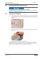
1.
Position the I/O module so that the tongue and groove joints to the fieldbus
coupler/controller or to the previous or possibly subsequent I/O module are
engaged.
Figure 8: Insert I/O Module (Example)
2.
Press the I/O module into the assembly until the I/O module snaps into the
carrier rail.
Figure 9: Snap the I/O Module into Place (Example)
With the I/O module snapped in place, the electrical connections for the data
contacts and power jumper contacts (if any) to the fieldbus coupler/controller or to
the previous or possibly subsequent I/O module are established.
Manual
Version 1.3.0
42
Mounting
6.2.2
WAGO-I/O-SYSTEM 750
750-652 Serial Interface RS-232 / RS-485
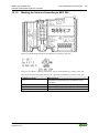
Removing the I/O Module
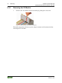
1.
Remove the I/O module from the assembly by pulling the release tab.
Figure 10: Removing the I/O Module (Example)
Electrical connections for data or power jumper contacts are disconnected when
removing the I/O module.
Manual
Version 1.3.0
WAGO-I/O-SYSTEM 750
750-652 Serial Interface RS-232 / RS-485
7
Connect Devices
43
Connect Devices
Use shielded signal lines!
Only use shielded signal lines for analog signals and I/O modules which are
equipped with shield clamps. Only then can you ensure that the accuracy and
interference immunity specified for the respective I/O module can be achieved
even in the presence of interference acting on the signal cable.
7.1
Connecting a Conductor to the CAGE CLAMP®
The WAGO CAGE CLAMP® connection is appropriate for solid, stranded and
finely stranded conductors.
Only connect one conductor to each CAGE CLAMP®!
Only one conductor may be connected to each CAGE CLAMP®.
Do not connect more than one conductor at one single connection!
If more than one conductor must be routed to one connection, these must be
connected in an up-circuit wiring assembly, for example using WAGO feedthrough terminals.
Exception:
If it is unavoidable to jointly connect 2 conductors, then you must use a ferrule to
join the wires together. The following ferrules can be used:
Length:
8 mm
Nominal cross section max.:
1 mm2 for 2 conductors with 0.5 mm2 each
WAGO product:
216-103 or products with comparable properties
1.
For opening the CAGE CLAMP® insert the actuating tool into the opening
above the connection.
2.
Insert the conductor into the corresponding connection opening.
3.
For closing the CAGE CLAMP® simply remove the tool. The conductor is
now clamped firmly in place.
Manual
Version 1.3.0
44
Connect Devices
WAGO-I/O-SYSTEM 750
750-652 Serial Interface RS-232 / RS-485
Figure 11: Connecting a Conductor to a CAGE CLAMP®
7.2
Connection Examples
7.2.1
RS-232 Operating Mode
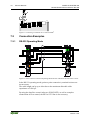
Figure 12: Point-to-Point Connection Operating Mode RS-232 with RTS/CTS Data Flow Control
In the RS-232 operating mode (point-to-point connection), terminal resistors are
not necessary.
The cable length can be up to 40 m due to the maximum allowable cable
capacitance of 1500 pF.
By using the data flow control software (XON/XOFF), as well as complete
renunciation of flow control, the RTS-to-CTS line is not necessary.
Manual
Version 1.3.0
WAGO-I/O-SYSTEM 750
750-652 Serial Interface RS-232 / RS-485
7.2.2
Connect Devices
45
RS-485 Operating Mode
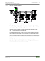
Figure 13: Bus Connection RS-485 Operating Mode, Half-Duplex
In the RS-485 operating mode (bus connection), a twisted-pair cable should be
used at least for larger cable lengths or higher transmission rates. The ends of the
cable should be terminated with a terminal resistor.
Generally, a passive resistance is used by connecting the signal lines via one
100 … 120 Ω resistor apiece to both bus ends.
For communication between 2 or more 750-652 interface modules at low baud
rates or with shorter line lengths, it is not necessary to use the terminal resistors.
The receiver built into the I/O module has a defined output state if both inputs are
not connected and the data line has a short circuit or no transmitter is active (idle
line).
If the 750-652 serial interface module works on a network with other
communication partners, the wiring of a resistance-biasing network (known as a
fail-safe network) to one line end can be necessary.
Manual
Version 1.3.0
46
Connect Devices
WAGO-I/O-SYSTEM 750
750-652 Serial Interface RS-232 / RS-485
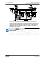
Figure 14: Bus Connection RS-485 Operating Mode with Biasing Network, Half-Duplex
With the use of the biasing resistors, it is guaranteed in this case that all receiver
inputs A have the voltage difference of more than 200 mV to the inputs B if no
transmitter is active. The oscillations of the receiver that can cause defective
reception are thus prevented.
Biasing network
Check the necessity of an external biasing network before start-up.
In modern devices with RS-485/RS-422 interface, this network is either already
integrated or the devices have an improved RS-485/RS-422 receiver. The output
of this receiver is in a defined state if the data line is short-circuited or not active.
Manual
Version 1.3.0
WAGO-I/O-SYSTEM 750
750-652 Serial Interface RS-232 / RS-485
7.2.3
Connect Devices
47
RS-422 Operating Mode
Figure 15: Bus Connection RS-422 Operating Mode
For the RS-422 operating mode (point-to-point connection), the bus ends (at least
for longer line lengths and greater baud rates) should be terminated with a
terminal resistor.
Generally a passive resistance is used by connecting the signal lines via one
100 ... 120 Ω resistor apiece to both bus ends.
For communication between 2 or several 750-652 interface modules at low baud
rates or with shorter line lengths, it is not necessary to use the terminal resistors.
If the 750-652 serial interface module works on a network with other
communication partners, the wiring of a resistance-biasing network (known as a
fail-safe network) to one line end can be necessary.
Biasing network
Check the necessity of an external biasing network before start-up.
In modern devices with RS-485/RS-422 interface, this network is either already
integrated or the devices have an improved RS-485/RS-422 receiver. The output
of this receiver is in a defined state if the data line is short-circuited or not active.
7.2.4
DMX Operating Mode
In the DMX operating mode, the wiring is based on the RS-485 operating mode.
Manual
Version 1.3.0
48
Connect Devices
7.2.5
WAGO-I/O-SYSTEM 750
750-652 Serial Interface RS-232 / RS-485
Data Exchange Mode
Figure 16: Point-to-Point Connection Between Two Nodes
In this mode, the contacts of the I/O modules to connect are connected to each
other crosswise.
In the Data Exchange operating mode (point-to-point connection), a twisted-pair
cable should be used at least for larger cable lengths. Two wire pairs and one
ground wire are required. The ends of the cable should be terminated with a
terminal resistor.
Generally, a passive resistance is used by connecting the signal lines via one
100 … 120 Ω resistor apiece to the ends of the of the cable (A-B).
Manual
Version 1.3.0
WAGO-I/O-SYSTEM 750
750-652 Serial Interface RS-232 / RS-485
Commissioning
8
Commissioning
8.1
Configuration and Parameterization with
WAGO-I/O-CHECK
49
The serial interface module is configured with the WAGO-I/O-CHECK software
(version 3.3 or higher, WAGO-I/O-CHECK version 3.5.3 is required for firmware
version 03 or higher). The software's basic functionality is described separately in
the WAGO-I/O-CHECK documentation.
Component damage due to incorrect voltage level!
Incorrectly selected voltage levels can destroy the device!
Note when switching between operating modes that RS-232 and RS-485 use
different voltage levels.
Switch off connected devices before changing operating modes!
Make sure that devices you connect support the voltage level of the current
operating mode!
8.1.1
RS-232 / RS-485 Serial Interface (Configuration Dialog)
Figure 17: Parameter Dialog
Manual
Version 1.3.0
50
Commissioning
WAGO-I/O-SYSTEM 750
750-652 Serial Interface RS-232 / RS-485
The parameter dialog is divided into the following areas:
•
Title bar with item and item number of the selected I/O module, info area
with item number, designation, and version number and version date of the
I/O module,
•
•
•
Toolbar (1),
Parameter range (2) and
Status bar (3).
Status reports are output in the status display in the lower area of the configuration
dialog.
8.1.2
Toolbar on the Configuration Dialog
The toolbar contains the following buttons:
Figure 18: Toolbar
Table 22: Toolbar
Button
Function
Exit
Description
Closes the active window. If you have changed
settings, you will be asked to save these values in
the I/O module.
Open
Opens a file with saved parameters. WAGO-I/OCHECK shows the Open File dialog.
Save
Saves the current parameters in a file. WAGO-I/OCHECK shows the Save File dialog.
Read
Reads the current settings from the connected I/O
module.
Write
Writes the current parameters to the selected I/O
module.
Factory
settings
Overwrites the locally-saved configuration and
parameterization with factory settings.
Manual
Version 1.3.0
WAGO-I/O-SYSTEM 750
750-652 Serial Interface RS-232 / RS-485
Commissioning
51
Table 22: Toolbar
Button
Function
Description
Configuration Sets the process image size.
Help
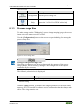
8.1.3
Opens the WAGO-I/O-CHECK online help.
Process Image Size
To make settings on the "PI Mapping" (process image mapping) page, the process
image size of the master must be set first.
Use the [Configuration] button on the toolbar to open the dialog for entering the
process image size.
Figure 19: Process Image Size
Changes to the process image size!
Note that with changes to the process data length, the structure of the process
image changes, and if necessary, changes to the configuration of the superior
controller may be necessary.
The following selection box is displayed:
Table 23: PI Size
Selection box
Process image size
*)
Default setting
Settings
8 bytes, 24 bytes*, 48 bytes
With the [Apply] button, you transfer the changed parameters to the non-volatile
memory of the I/O module. A software reset is conducted so that the changes take
effect. The dialog remains open.
Manual
Version 1.3.0
52
Commissioning
WAGO-I/O-SYSTEM 750
750-652 Serial Interface RS-232 / RS-485
With the [Default] button, you select the default setting for this I/O module. With
the [Apply] button, you then transfer the parameters to the non-volatile memory
of the I/O module.
With the [Close] button, you close the configuration dialog without transferring
any changed parameters to the non-volatile memory of the I/O module.
8.1.4
Parameter Range
Figure 20: Parameter Range
The following selection boxes are displayed in tabular form. The possible settings
are described in more detail in the chapter “Function Description”.
Table 24: Parameter Range
Selection box
Operating Mode
Transmission Rate [Baud]
Data Bits
Parity
Stop bits
Flow Control
Continuous Send Mode
(Continuous Send)
Continuous Receive Mode
(Continuous Receive)
Possible settings
RS-232 / RS-485 half-duplex* / RS-422 full-duplex
/ data exchange RS-4224) / DMX halfduplex/250k4)
300 baud / 600 baud / 1200 baud / 2400 baud /
4800 baud / 9600 baud* / 19200 baud /
38400 baud / 57600 baud / 115200 baud
8*/ 7
none* / odd / even
1* / 2
disabled* / XON/XOFF1) / RTS/CTS2) / RTS, lead
and follow-on time4)
disabled* / release
disabled* / release
Manual
Version 1.3.0
WAGO-I/O-SYSTEM 750
750-652 Serial Interface RS-232 / RS-485
Commissioning
53
Table 24: Parameter Range
Selection box
Possible settings
3)
Switchover Time RS-485
100 µs* / 2 Characters / 4 Characters
Continuous Receive Timeout 2 Characters* / 4 Characters
*
Default setting
1)
The setting is relevant for the operating mode RS-232/RS-422, full-duplex.
2) The setting is relevant for the operating mode RS-232.
3)
The setting is relevant for the operating mode RS-485, half-duplex.
4)
Firmware version 03 or higher
Use of the CODESYS library "SerComm.lib"
Note that following settings for use of the I/O module with programmable
fieldbus controllers and use of the CODESYS library "SerComm.lib" can be
temporarily overwritten by the controller:
•
Mode
•
Baud rate
•
Data bits, parity, number of stop bits
•
Flow control
•
Continuous send
The following values are not available if settings should be changed by the
CODESYS library "SerComm.lib":
•
Mode: Data Exchange, DMX
•
Baud rate: 600 baud
•
Flow control: RTS with lead/follow-on time
8.1.5
Setting the RS-232 / RS-485 Serial Interface
Open the configuration dialog for the serial interface module. To do so, execute
the command Settings in the context menu of the I/O module (node view or
navigation).
Important note:
Before changing the parameters you should save the current values in a
parameter file. This way, in case the parameters are wrong, you can always fall
back on the original values. Use the [Save] and [Open] buttons in the parameter
dialog.
The serial I/O module is configured and prepared for communication in the
configuration area.
In order to display the default values for this I/O module (except for the size of the
process image), press the [Default] button. The values indicated can then be
changed further.
Manual
Version 1.3.0
54
Commissioning
WAGO-I/O-SYSTEM 750
750-652 Serial Interface RS-232 / RS-485
To change settings in the serial I/O module, adjust the values in the configuration
area.
Changed settings are marked with a change symbol (pen symbol) in order to
indicate that these values no longer match the values originally queried by the
module.
To transfer the new values to the I/O module, click the [Write] button.
You can also put the I/O module into another operating mode. Here the changed
configuration is saved and the inputs and outputs of the I/O module are switched
immediately according to the operating mode.
Input operating mode!
In case of a change of operating mode, a warning appears that points out that it
may be necessary to change the wiring.
8.2
Configuration and Parameterization via GSD for
PROFIBUS DP and PROFINET IO
Other methods are available for configuration depending on the fieldbus
coupler/controller. These are described in the appendix.
8.3
Data Transfer
The following chapters describe data transfer in all operating modes for serial
transmission and in the Data Exchange operating mode.
8.3.1
Example of Operating Modes for Serial Transmission
The control of the transmission and receipt operation is handled with the control
and status byte. Requests are indicated by the change (toggle) of a bit. The
successful processing is indicated by an assigned bit. It takes the value of the
request bit.
Initialize I/O module:
•
Setting of IR in control byte C0
•
Initialization of the I/O module
•
Blocking of the transmit and receive functions
•
Deletion of the transmit and receive memory
•
Loading of the configuration data in the serial I/O module
Manual
Version 1.3.0
WAGO-I/O-SYSTEM 750
750-652 Serial Interface RS-232 / RS-485
Commissioning
55
Transmit data:
•
TR = TA: Writing of the characters to be transmitted in output bytes D0 to
Dn
•
Number of characters to be transmitted is specified in OL0 to OL5
•
Inversion and output of TR
•
Transfer to the output buffer takes place when TR = TA
Receive data:
•
RR ≠ RA: in input byte 0 to n characters are available
•
Number of characters received is specified in IL0 to IL5
•
Reading out of the characters in IL0 to IL5
•
Inversion and output of RA
•
Reading out has taken place when RR = RA
The transmission and receipt of data between controller and I/O module can take
place simultaneously. The initialization request is executed with priority and
immediately ends the transmission and receipt of data.
Reset initialization bit!
The initialization bit in control byte C0 must be reset. As long as the initialization
bit is set, no data is exchanged. The initialization bit can be reset simultaneously
with transmission of the initial data.
Always read received data!
The input buffer of the I/O module is 80% full if the BUF_F bit is set in status
byte 0. If the input buffer if full, the I/O module cannot receive any further data
via the serial interface. Any data transmitted by an external device is lost.
8.3.2
Initialization
The I/O module is initialized.
The initialization bit is set in the control byte 0.
Table 25: Initialization Bit
Control byte 0
Control byte 1
Output byte 0
Output byte 1
'0000.0000'
XX
XX
'0000.0100'
The execution of the initialization is acknowledged by the I/O module with the
setting of the bit IA.
Table 26: Initialization of the I/O Module
Status byte 0 Status byte 1
Input byte 0
XXXX. X1XX'
Manual
Version 1.3.0
'XXXX. 1XXX'
XX
Input byte 1
XX
The I/O module is initialized.
56
Commissioning
WAGO-I/O-SYSTEM 750
750-652 Serial Interface RS-232 / RS-485
Control requests data exchange:
Table 27: Data Exchange
Control byte 0
'0000.0000'
Control byte 1
'0000.0000'
Output byte 0
XX
Output byte 1
XX
The IA bit is reset by the I/O module.
Table 28: I/O Module Is Ready
Status byte 0
Status byte 1
'0XXX. X0XX' '0XXX. 1XXX'
8.3.3
Input byte 0
XX
Input byte 1
XX
The I/O module is ready.
Transmission of the Character String "Hello World!"
The eleven characters, the reset initialization bit, and the length 11 are
transmitted.
Table 29: Character string "Hello World"
Control byte 0
Control byte 1
'0011.0000'
'0000.0001'
Output byte 2
Output byte 3
"1" (0x6C)
"1" (0x6C)
Output byte 6
Output byte 7
"W" (0x87)
"e" (0x65)
Output byte 10
Output byte 11
"!" 0 x 21
XX
Output byte 0
"H" (0x48)
Output byte 4
"o" (0x6F)
Output byte 8
"1" (0x6C)
Output byte 12
XX
Output byte 1
"a" (0x60)
Output byte 5
0 x 20
Output byte 9
"t" (0x74)
Output byte 13
XX
Output byte 0
"H" (0x48)
Output byte 4
"o" (0x6F)
Output byte 8
"1" (0x6C)
Output byte 12
XX
Output byte 1
"a" (0x60)
Output byte 5
0 x 20
Output byte 9
"t" (0x74)
Output byte 13
XX
The transmit request bit TR is inverted.
Table 30: Transmit Request Bit TR
Control byte 0
Control byte 1
'0011.0001'
'0000.0001'
Output byte 2
Output byte 3
"1" (0x6C)
"1" (0x6C)
Output byte 6
Output byte 7
"W" (0x87)
"e" (0x65)
Output byte 10
Output byte 11
"!" 0 x 21
XX
The data was transmitted to the output buffer as soon as TA = TR. Then additional
characters can be transmitted.
Table 31: Data Transfer
Status byte 0
Status byte 1
'0XXX.XXX0' '0XXX. 1XXX'
Input byte 0
XX
Input byte 1
XX
'0XXX.XXX1' '0XXX. 1XXX'
XX
XX
The data transfer is still
running.
When the data transfer has
taken place, the data is
transmitted via the serial
interface.
Manual
Version 1.3.0
WAGO-I/O-SYSTEM 750
750-652 Serial Interface RS-232 / RS-485
8.3.4
Commissioning
57
Receiving the Character String "WAGO"
As soon as RA ≠ RR, characters are available in the input byte.
Table 32: Output Process Image
Control byte 0
Control byte 1
'0XXX XX0X
'0XXX.XXXX'
Table 33: Receive Data
Status byte 0
Status byte 1
0-xxx X (00x) '0XXX. 1XXX'
'0XX1. 001X'
'0XXX. 1XXX'
Output byte 0
XX
Input byte 0
XX
Input byte 1
XX
"W"
"A"
Output byte 1
XX
There are no receive data
available.
The data is available in the
input bytes.
After the 2 characters have been processed, RA is inverted.
Table 34: Receive 2 Characters
Control byte 0
Control byte 1
'0XXX XX1X
'0XXX.XXXX'
Output byte 0
XX
Output byte 1
XX
The receipt of additional characters is indicated by different values for RA and
RR.
Table 35: Receipt of Additional Characters
Status byte 0
Status byte 1
Input byte 0
'0XXX. X01X' '0XXX. 1XXX'
XX
'0XX1. 000X'
'0XXX. 1XXX'
"G"
Input byte 1
XX
"O"
There are no receive data
available.
The data is available in the
input bytes.
After the characters have been processed, RA is inverted.
Table 36: Output Process Image After Data Transfer
Control byte 0
Control byte 1
'0XXX XX0X
'0XXX.XXXX'
Output byte 0
XX
8.3.5
Operation with Continuous Send
8.3.5.1
Transmission of a Block of One to 512 Bytes
Output byte 1
XX
The output buffer is filled up with data up to number n (n ≤ 512 bytes)
To transmit the buffer content, the bit 3 (SC) of the control byte 0 is set by the
controller. The I/O module begins with the data transmission and the bit 3
(BUF_E) of the status byte 1 is reset.
If all data is transmitted, the bit 3 (BUF_E) of the status byte 1 is set.
The controller takes bit 3 (SC) of the control byte 0 back from the controller. The
end of the transmission from the I/O module is detected this way.
Manual
Version 1.3.0
58
Commissioning
WAGO-I/O-SYSTEM 750
750-652 Serial Interface RS-232 / RS-485
Table 37: Transmission of a Block of One to 512 Bytes
Control byte 0
Control byte 1
'0110.1001'
'0XXX. X101'
Controller fills the output buffer with 46 bytes and set bit
3 (SC) of the control byte 0 for the start of the
transmission.
Status byte 0
Status byte 1
'0XXX.X0X1'
'0000. 1XXX'
I/O module confirms the acceptance of the data.
Control byte 0
Control byte 1
'0110.1000'
'0XXX. X101'
Controller takes bit 0 (TR) of the control byte 0 back.
Status byte 0
Status byte 1
'0XXX.X0X0'
'0XXX. 0XXX' I/O module begins with the data transmission via the
serial interface.
Status byte 0
Status byte 1
'0XXX.X0X1'
'0000. 1XXX'
All data is transmitted via the serial interface.
Control byte 0
Control byte 1
'0XXX.0XX0'
'0XXX. 1XXX' Controller takes bit 3 (TR) of the control byte 0 back.
8.3.5.2
Transmission of a Block of More than 512 Bytes
The output buffer is filled up with data up to number 512 bytes.
To transmit the buffer content, the bit 3 (SC) of the control byte 0 is set by the
controller. The I/O module begins with the data transmission and the bit 3
(BUF_E) of the status byte 1 is reset.
During transmission, the output buffer continues to be filled up by the controller.
Bit 3 (SC) of control byte 0 is set by the controller as long as data should be
transmitted. The I/O module acknowledges data transmission by resetting bit 3
(BUF_E) in status byte 1.
Then bit 3 (SC) of control byte 0 is taken back by the controller. The end of the
transmission from the I/O module is detected this way.
NOTE
At higher baud rates, it cannot be ensured that more than 512 bytes of data are
transmitted as a contiguous block!
Manual
Version 1.3.0
WAGO-I/O-SYSTEM 750
750-652 Serial Interface RS-232 / RS-485
Commissioning
59
Table 38: Transmission of a Block of More than 512 Bytes*)
Control byte 0
Control byte 1
'0110.1001'
'0XXX. X101'
Status byte 0
'0XXX.X0X1'
Control byte 0
'0110.1000'
Status byte 0
'0XXX.X0X0'
Status byte 1
'0000. 1XXX'
Control byte 1
'0XXX. X101'
Status byte 1
'0XXX. 0XXX'
Control byte 0
'0110.1001'
Control byte 1
'0XXX. X101'
Status byte 0
'0XXX.X0X1'
Status byte 0
'0XXX.X0X1'
Status byte 1
'0000. 0XXX'
Status byte 1
'0000. 1XXX'
Control byte 0
'0110.1001'
Control byte 1
'0XXX. X101'
Status byte 0
'0XXX.X0X1'
Status byte 0
'0XXX.X0X0'
Status byte 1
'0000. 0XXX'
Status byte 1
'0XXX. 0XXX'
Status byte 0
'0XXX.X0X1'
Status byte 1
'0000. 1XXX'
Controller fills the output buffer with 46 bytes and set bit
3 (SC) of the control byte 0 for the start of the
transmission.
Bit 3 (SC) of the control byte 0 must always be set if the
controller transmits more than 512 bytes of data to the
I/O module.
I/O module confirms the acceptance of the data.
Controller takes bit 0 (TR) of the control byte 0 back.
I/O module begins with the data transmission via the
serial interface.
Controller fills the output buffer with another 46 bytes of
data.
I/O module confirms the acceptance of the data.
All data saved in the output buffer is transmitted via the
serial interface.
Controller fills the output buffer with another 46 bytes of
data.
I/O module confirms the acceptance of the data.
I/O module continues the data transmission via the serial
interface.
All data saved in the output buffer is transmitted via the
serial interface.
Control byte 0
Control byte 1
'0XXX.0XX0'
'0XXX. 1XXX' Controller takes bit 3 (SC) of the control byte 0 back.
*)
The table shows the transmission method from the time at which more than 500 bytes is in the
output buffer.
Important Note:
An X is used if the value is not relevant here.
An XX means that the entire value is not relevant.
Manual
Version 1.3.0
60
Commissioning
WAGO-I/O-SYSTEM 750
750-652 Serial Interface RS-232 / RS-485
8.3.6
DMX Application Example
8.3.6.1
Operation with Deactivated Continuous Send
In this mode, the I/O module only transmits the data for a limited number of DMX
channels according to the set size of the process image (see table “Process data in
the DMX operating mode without continuous send”). Higher refresh rates are then
possible.
Table 39: Process Data in the DMX Operating Mode Without Transfer Optimization
Process Input data
image
length
8 bytes S0 Status byte 0
S1 Status byte 1
D0 Data byte 0*)
D1 Data byte 1*)
D2 Data byte 2*)
…
D5 Data byte 5*)
24 bytes D6 Data byte 6*)
…
D21 Data byte 21*)
48 bytes D22 Data byte 22*)
…
D45 Data byte 45*)
*)
Output data
C0
C1
D0
D1
D2
…
D5
D6
…
D21
D22
…
D45
Control byte 0
Control byte 1
Data byte 0 DMX start byte (always 0)
Data byte 1 (DMX channel 1)
Data byte 2 (DMX channel 2)
Data byte 5 (DMX channel 5)
Data byte 6 (DMX channel 6)
Data byte 21 (DMX channel 21)
Data byte 22 (DMX channel 22)
Data byte 45 (DMX channel 45)
Not in use. In this mode, no data is received.
The transmission method is described in the chapter “Transmission of the
Character String 'Hello World!'”
8.3.6.2
Operation with Activated Continuous Send
In this mode, the output buffer filled with the DMX start byte (always 0) and then
with data for DMX channel 1 to 254.
The transmission method is described in the chapter “Function Description > … >
“Continuous Transmission”.
Observe settings!
To ensure continuous transmission, the “Continuous Send” setting must be
activated!
Manual
Version 1.3.0
WAGO-I/O-SYSTEM 750
750-652 Serial Interface RS-232 / RS-485
8.3.7
Commissioning
61
Data Exchange Operating Mode Application Example
In the “Data Exchange” operating mode, the I/O module monitors process data
exchange with the partner module. If the connection is interrupted for 200 ms or
more, it generates a diagnosis in the status byte. This monitoring only takes into
account if there is a connection between the I/O modules. As the user, you may
want to check if the application that accesses the fieldbus node of the opposite
side as a PLC application or via fieldbus has received the information sent.
You can easily implement this monitoring by reserving three bits in the data part
of the process image for transmission of status information. Use bits 0, 1 and 2 of
the first data byte, for example.
Use bit 0 as the “ON” signal on both sides.
1.
Describe bit 0 in the process image (output) permanently with status 1.
2.
Check if the “ON” signal is displayed correctly in the process image (input).
No connection if the status is “0”
If the status is 0, there is no connection with the opposite side and all data bytes of
the process image (input) of the I/O module are invalid.
Use bit 1 as the “toggle” bit to send data to the opposite side.
3.
Invert the sent “toggle” bit if you want to send new data.
If you have already sent data, you can only send new data if the opposite has
acknowledged receipt.
Use bit 2 as the “acknowledge” bit on both sides to signal data receipt to the
respective opposite side.
4.
Manual
Version 1.3.0
Always invert the sent “acknowledge” bit if the received “toggle” bit has
changed.
62
Diagnostics
WAGO-I/O-SYSTEM 750
750-652 Serial Interface RS-232 / RS-485
9
Diagnostics
9.1
Serial Operating Modes
Table 40: Diagnostics, Serial Operating Modes
Diagnostics
Event
Input buffer full The I/O module receives
data via the serial interface
faster than accepted by the
application.
Output buffer
full
Parity error
Overflow
9.2
Solution
• Make sure that the application
always accepts data
immediately
• Reduce data traffic
• Use flow control
• Reduce baud rate
The I/O module receives
• Check continuous send
data faster from the
• Reduce data traffic
application than it sends via • Increase baud rate
the serial interface.
• Make sure that the opposite
side accepts data
Data transmission was
• Check the configuration of the
interrupted.
interface parameters
• Use a shielded cable
• Change wire routing
• Shorten cable
• Eliminate interference
Data loss has occurred.
• Reduce baud rate
Data Exchange Operating Mode
Table 41: Diagnostics, Data Exchange
Diagnostics
Wrong length
Event
The I/O modules have
different process image
sizes
Checksum error Data transmission was
interrupted. The last valid
value is retained in the
process image.
Timeout
The data transmission is
interrupted or has been
interrupted for a longer
period of time (see
checksum error). The
process image (input) has
been overwritten with the
value 0.
Solution
• Configure the same process
image size
•
•
•
•
•
•
•
Use a shielded cable
Change wire routing
Shorten cable
Eliminate interference
Check cable and clamping
points for uniformity
Check the configuration of the
I/O modules
for checksum error: See
Diagnostics “Checksum error”
Manual
Version 1.3.0
WAGO-I/O-SYSTEM 750
750-652 Serial Interface RS-232 / RS-485
10
Use in Hazardous Environments
63
Use in Hazardous Environments
The WAGO-I/O-SYSTEM 750 (electrical equipment) is designed for use in
Zone 2 hazardous areas.
The following sections include both the general identification of components
(devices) and the installation regulations to be observed. The individual
subsections of the “Installation Regulations” section must be taken into account if
the I/O module has the required approval or is subject to the range of application
of the ATEX directive.
Manual
Version 1.3.0
64
Use in Hazardous Environments
WAGO-I/O-SYSTEM 750
750-652 Serial Interface RS-232 / RS-485
10.1
Marking Configuration Examples
10.1.1
Marking for Europe According to ATEX and IEC-Ex
Figure 21: Side Marking Example for Approved I/O Modules According to ATEX and IECEx
Figure 22: Text Detail – Marking Example for Approved I/O Modules According to ATEX and
IECEx.
Manual
Version 1.3.0
WAGO-I/O-SYSTEM 750
750-652 Serial Interface RS-232 / RS-485
Use in Hazardous Environments
65
Table 42: Description of Marking Example for Approved I/O Modules According to ATEX and
IECEx
Printing on Text
TÜV 07 ATEX 554086 X
IECEx TUN 09.0001 X
Dust
II
3D
Ex
tc Dc
IIIC
T 135°C
Mining
I
M2
Ex
d Mb
I
Gases
II
3G
Ex
nA Gc
nC Gc
IIC
T4
Manual
Version 1.3.0
Description
Approving authority and certificate numbers
Equipment group: All except mining
Category 3 (Zone 22)
Explosion protection mark
Type of protection and equipment protection
level (EPL):protection by enclosure
Explosion group of dust
Max. surface temperature of the enclosure
(without a dust layer)
Equipment group: Mining
Category: High level of protection
Explosion protection mark
Type of protection and equipment protection
level (EPL): Flameproof enclosure
Explosion group for electrical equipment for
mines susceptible to firedamp
Equipment group: All except mining
Category 3 (Zone 2)
Explosion protection mark
Type of protection and equipment protection
level (EPL): Non-sparking equipment
Type of protection and equipment protection
level (EPL): Sparking apparatus with protected
contacts. A device which is so constructed that
the external atmosphere cannot gain access to the
interior
Explosion group of gas and vapours
Temperature class: Max. surface temperature
135°C
66
Use in Hazardous Environments
WAGO-I/O-SYSTEM 750
750-652 Serial Interface RS-232 / RS-485
Figure 23: Side Marking Example for Approved Ex i I/O Modules According to ATEX and
IECEx.
Figure 24: Text Detail – Marking Example for Approved Ex i I/O Modules According to ATEX
and IECEx.
Manual
Version 1.3.0
WAGO-I/O-SYSTEM 750
750-652 Serial Interface RS-232 / RS-485
Use in Hazardous Environments
67
Table 43: Description of Marking Example for Approved Ex i I/O Modules According to ATEX and
IECEx
Inscription Text
TÜV 07 ATEX 554086 X
IECEx TUN 09.0001X
TÜV 12 ATEX 106032 X
IECEx TUN 12.0039 X
Dust
II
3(1)D
3(2)D
Ex
tc Dc
[ia Da]
[ib Db]
IIIC
T 135°C
Mining
I
M2 (M1)
Ex d Mb
[ia Ma]
I
Manual
Version 1.3.0
Description
Approving authority and certificate numbers
Equipment group: All except mining
Category 3 (Zone 22) equipment containing a safety
device for a category 1 (Zone 20) equipment
Category 3 (Zone 22) equipment containing a safety
device for a category 2 (Zone 21) equipment
Explosion protection mark
Type of protection and equipment protection level
(EPL): protection by enclosure
Type of protection and equipment protection level
(EPL): associated apparatus with intrinsic safety
circuits for use in Zone 20
Type of protection and equipment protection level
(EPL): associated apparatus with intrinsic safety
circuits for use in Zone 21
Explosion group of dust
Max. surface temperature of the enclosure (without a
dust layer)
Equipment Group: Mining
Category: High level of protection with electrical
circuits which present a very high level of protection
Explosion protection mark with Type of protection
and equipment protection level (EPL): Flameproof
enclosure
Type of protection and equipment protection level
(EPL): associated apparatus with intrinsic safety
electrical circuits
Explosion group for electrical equipment for mines
susceptible to firedamp
68
Use in Hazardous Environments
WAGO-I/O-SYSTEM 750
750-652 Serial Interface RS-232 / RS-485
Table 43: Description of Marking Example for Approved Ex i I/O Modules According to ATEX and
IECEx
Gases
II
3(1)G
3(2)G
Ex
nA Gc
[ia Ga]
[ia Gb]
IIC
T4
Equipment group: All except mining
Category 3 (Zone 2) equipment containing a safety
device for a category 1 (Zone 0) equipment
Category 3 (Zone 2) equipment containing a safety
device for a category 2 (Zone 1) equipment
Explosion protection mark
Type of protection and equipment protection level
(EPL): Non-sparking equipment
Type of protection and equipment protection level
(EPL): associated apparatus with intrinsic safety
circuits for use in Zone 0
Type of protection and equipment protection level
(EPL): associated apparatus with intrinsic safety
circuits for use in Zone 1
Explosion group of gas and vapours
Temperature class: Max. surface temperature 135°C
Manual
Version 1.3.0
WAGO-I/O-SYSTEM 750
750-652 Serial Interface RS-232 / RS-485
10.1.2
Use in Hazardous Environments
Marking for America According to NEC 500
Figure 25: Side Marking Example for I/O Modules According to NEC 500
Figure 26: Text Detail – Marking Example for Approved I/O Modules According to NEC 500
Table 44: Description of Marking Example for Approved I/O Modules According to NEC 500
Printing on Text
CL I
DIV 2
Grp. ABCD
Op temp code T4
Manual
Version 1.3.0
Description
Explosion protection group (condition of use
category)
Area of application
Explosion group (gas group)
Temperature class
69
70
Use in Hazardous Environments
10.2
WAGO-I/O-SYSTEM 750
750-652 Serial Interface RS-232 / RS-485
Installation Regulations
For the installation and operation of electrical equipment in hazardous areas, the
valid national and international rules and regulations which are applicable at the
installation location must be carefully followed.
Manual
Version 1.3.0
WAGO-I/O-SYSTEM 750
750-652 Serial Interface RS-232 / RS-485
10.2.1
Use in Hazardous Environments
71
Special Conditions for Safe Use (ATEX Certificate TÜV 07
ATEX 554086 X)
1.
2.
3.
4.
5.
6.
7.
Manual
Version 1.3.0
For use as Gc- or Dc-apparatus (in zone 2 or 22) the Field bus Independent
I/O Modules WAGO-I/O-SYSTEM 750-*** shall be erected in an
enclosure that fulfils the requirements of the applicable standards (see the
marking) EN 60079-0, EN 60079-11, EN 60079-15 and EN 60079-31.
For use as group I electrical apparatus M2 the apparatus shall be erected in
an enclosure that ensures a sufficient protection according to EN 60079-0
and EN 60079-1 and the degree of protection IP64.
The compliance of these requirements and the correct installation into an
enclosure or a control cabinet of the devices shall be certified by an ExNB.
Measures have to be taken outside of the device that the rating voltage is not
being exceeded of more than 40 % because of transient disturbances.
Dip-switches, binary-switches and potentiometers, connected to the module
may only be actuated when explosive atmosphere can be excluded.
The connecting and disconnecting of the non-intrinsically safe circuits is
only permitted during installation, for maintenance or for repair purposes.
The temporal coincidence of explosion hazardous atmosphere and
installation, maintenance resp. repair purposes shall be excluded.
This is although and in particular valid for the interfaces “Memory-Card”,
“USB”, “Fieldbus connection”, “Configuration and programming interface”,
“antenna socket”, “D-Sub”, “DVI-port” and the “Ethernet interface”. These
interfaces are not energy limited or intrinsically safe circuits. An operating
of those circuits is in the behalf of the operator.
For the types 750-606, 750-625/000-001, 750-487/003-000, 750-484 and
750-633 the following shall be considered: The Interface circuits shall be
limited to overvoltage category I/II/III (non mains/mains circuits) as defined
in EN 60664-1.
For replaceable fuses the following shall be considered: Do not remove or
replace the fuse when the apparatus is energized.
The following warnings shall be placed nearby the unit:
WARNING – DO NOT REMOVE OR REPLACE FUSE WHEN
ENERGIZED
WARNING – DO NOT SEPARATE WHEN ENERGIZED
WARNING – SEPARATE ONLY IN A NON-HAZARDOUS AREA
72
Use in Hazardous Environments
10.2.2
WAGO-I/O-SYSTEM 750
750-652 Serial Interface RS-232 / RS-485
Special Conditions for Safe Use (ATEX Certificate TÜV 12
ATEX 106032 X)
1.
2.
3.
4.
For use as Gc- or Dc-apparatus (in zone 2 or 22) the Field bus Independent
I/O Modules WAGO-I/O-SYSTEM 750-*** Ex i shall be erected in an
enclosure that fulfils the requirements of the applicable standards (see the
marking) EN 60079-0, EN 60079-11, EN 60079-15 and EN 60079-31.
For use as group I electrical apparatus M2 the apparatus shall be erected in
an enclosure that ensures a sufficient protection according to EN 60079-0
and EN 60079-1 and the degree of protection IP64.
The compliance of these requirements and the correct installation into an
enclosure or a control cabinet of the devices shall be certified by an ExNB.
Measures have to be taken outside of the device that the rating voltage is not
being exceeded of more than 40 % because of transient disturbances.
The connecting and disconnecting of the non-intrinsically safe circuits is
only permitted during installation, for maintenance or for repair purposes.
The temporal coincidence of explosion hazardous atmosphere and
installation, maintenance resp. repair purposes shall be excluded.
For the type the following shall be considered: The Interface circuits shall
be limited to overvoltage category I/II/III (non mains/mains circuits) as
defined in EN 60664-1.
Manual
Version 1.3.0
WAGO-I/O-SYSTEM 750
750-652 Serial Interface RS-232 / RS-485
10.2.3
Use in Hazardous Environments
73
Special Conditions for Safe Use (IEC-Ex Certificate TUN
09.0001 X)
1.
2.
3.
4.
5.
6.
7.
Manual
Version 1.3.0
For use as Gc- or Dc-apparatus (in zone 2 or 22) the Field bus Independent
I/O Modules WAGO-I/O-SYSTEM 750-*** shall be erected in an
enclosure that fulfils the requirements of the applicable standards (see the
marking) IEC 60079-0, IEC 60079-11, IEC 60079-15 and IEC 60079-31.
For use as group I electrical apparatus M2 the apparatus shall be erected in
an enclosure that ensures a sufficient protection according to IEC 60079-0
and IEC 60079-1 and the degree of protection IP64.
The compliance of these requirements and the correct installation into an
enclosure or a control cabinet of the devices shall be certified by an ExCB.
Measures have to be taken outside of the device that the rating voltage is not
being exceeded of more than 40 % because of transient disturbances.
DIP-switches, binary-switches and potentiometers, connected to the module
may only be actuated when explosive atmosphere can be excluded.
The connecting and disconnecting of the non-intrinsically safe circuits is
only permitted during installation, for maintenance or for repair purposes.
The temporal coincidence of explosion hazardous atmosphere and
installation, maintenance resp. repair purposes shall be excluded.
This is although and in particular valid for the interfaces “Memory-Card”,
“USB”, “Fieldbus connection”, “Configuration and programming interface”,
“antenna socket”, “D-Sub”, “DVI-port” and the “Ethernet interface”. These
interfaces are not energy limited or intrinsically safe circuits. An operating
of those circuits is in the behalf of the operator.
For the types 750-606, 750-625/000-001, 750-487/003-000, 750-484 and
750-633 the following shall be considered: The Interface circuits shall be
limited to overvoltage category I/II/III (non mains/mains circuits) as defined
in IEC 60664-1.
For replaceable fuses the following shall be considered: Do not remove or
replace the fuse when the apparatus is energized.
The following warnings shall be placed nearby the unit:
WARNING – DO NOT REMOVE OR REPLACE FUSE WHEN
ENERGIZED
WARNING – DO NOT SEPARATE WHEN ENERGIZED
WARNING – SEPARATE ONLY IN A NON-HAZARDOUS AREA
74
Use in Hazardous Environments
10.2.4
WAGO-I/O-SYSTEM 750
750-652 Serial Interface RS-232 / RS-485
Special Conditions for Safe Use (IEC-Ex Certificate IECEx
TUN 12.0039 X)
1.
2.
3.
4.
For use as Gc- or Dc-apparatus (in zone 2 or 22) the Field bus independent
I/O Modules WAGO-I/O-SYSTEM 750-*** Ex i shall be erected in an
enclosure that fulfils the requirements of the applicable standards (see the
marking) IEC 60079-0, IEC 60079-11, IEC 60079-15, IEC 60079-31.
For use as group I electrical apparatus M2 the apparatus shall be erected in
an enclosure that ensures a sufficient protection according to IEC 60079-0
and IEC 60079-1 and the degree of protection IP64.
The compliance of these requirements and the correct installation into an
enclosure or a control cabinet of the devices shall be certified by an ExCB.
Measures have to be taken outside of the device that the rating voltage is not
being exceeded of more than 40 % because of transient disturbances.
The connecting and disconnecting of the non-intrinsically safe circuits is
only permitted during installation, for maintenance or for repair purposes.
The temporal coincidence of explosion hazardous atmosphere and
installation, maintenance resp. repair purposes shall be excluded.
For the type the following shall be considered: The Interface circuits shall
be limited to overvoltage category I/II/III (non mains/mains circuits) as
defined in IEC 60664-1.
Manual
Version 1.3.0
WAGO-I/O-SYSTEM 750
750-652 Serial Interface RS-232 / RS-485
10.2.5
Use in Hazardous Environments
75
Special Conditions for Safe Use according to ANSI/ISA
12.12.01
A.
B.
C.
D.
E.
F.
G.
H.
I.
J.
“This equipment is suitable for use in Class I, Division 2, Groups A, B, C, D
or non-hazardous locations only.”
“This equipment is to be fitted within tool-secured enclosures only.”
“WARNING Explosion hazard - substitution of components may impair
suitability for Class I, Div. 2.”
“WARNING – Do not disconnect equipment unless power has been
switched off or the area is known to be non-hazardous” has to be placed
near each operator accessible connector and fuse holder.
When a fuse is provided, the following information shall be provided: “A
switch suitable for the location where the equipment is installed shall be
provided to remove the power from the fuse.”
For devices with EtherCAT/Ethernet connectors “Only for use in LAN, not
for connection to telecommunication circuits.”
“WARNING - Use Module 750-642 only with antenna module 758-910.”
For Couplers/Controllers and Economy bus modules only: The instructions
shall contain the following: “The configuration interface Service connector
is for temporary connection only. Do not connect or disconnect unless the
area is known to be non-hazardous. Connection or disconnection in an
explosive atmosphere could result in an explosion.”
Modules containing fuses only: “WARNING - Devices containing fuses
must not be fitted into circuits subject to over loads, e.g. motor circuits.”
Modules containing SD card reader sockets only: “WARNING - Do not
connect or disconnect SD-Card while circuit is live unless the area is known
to be free of ignitable concentrations of flammable gases or vapors.”
Additional Information
Proof of certification is available on request.
Also take note of the information given on the operating and assembly
instructions.
The manual, containing these special conditions for safe use, must be readily
available to the user.
Manual
Version 1.3.0
76
Appendix
WAGO-I/O-SYSTEM 750
750-652 Serial Interface RS-232 / RS-485
11
Appendix
11.1
Configuration and Parameterization via GSD for
PROFIBUS DP and PROFINET IO
11.1.1
Configuration of the RS-232/RS-485 Interface
11.1.1.1
PROFIBUS DP (750-333, 750-343, 750-833) Fieldbus Coupler
PROFINET IO (750-370) Fieldbus Coupler
When using the aforementioned PROFIBUS-DP and PROFINET-IO fieldbus
couplers, the process image size is configured by selecting the corresponding PI
module type.
Table 45: Configuration
PI module type
Representatives of PI data type
the module type
75x-652 ser. interf. 8 bytes
75x-652 ser. interf. 24 bytes
75x-652
75x-652 ser. interf. 48 bytes
11.1.1.2
Unsigned8[2]
OctetString [6]
Unsigned8[2]
OctetString [22]
Unsigned8[2]
OctetString [46]
Instances
Inp.
Outp.
1
1
PROFINET IO (750-375, 750-377) Fieldbus Coupler
When using the aforementioned PROFIBUS-DP and PROFINET-IO fieldbus
couplers, the process image size is configured by selecting the corresponding
PI module / submodule type.
Table 46: Configuration
PI module
Represent PI submodule
type
atives of
type
the
module
type
{UINT8[2],
UINT8[6]} I/O
75x-652
{UINT8[2],
75x-652
serial
UINT8[22]} I/O
interface
{UINT8[2],
UINT8[46]} I/O
Process image
length
PI data type
8 bytes
Unsigned8[2]
OctetString [6]
Unsigned8[2]
OctetString [22]
Unsigned8[2]
OctetString [46]
24 bytes
48 bytes
Instances
Inp.
Outp
.
1
1
Manual
Version 1.3.0
WAGO-I/O-SYSTEM 750
750-652 Serial Interface RS-232 / RS-485
11.1.2
Appendix
77
Configuration of the RS-232/RS-485 Serial Interface
Apart from the RTS lead and follow-on time, the GSD file can be used to provide
the I/O module on the PROFIBUS DP and PROFINET IO fieldbus coupler with
all operating parameters.
Figure 27: Example of the PROFIBUS DP Fieldbus Coupler Configuration Dialog
Figure 28: Example of the 750-370 Fieldbus Coupler Configuration Dialog
Manual
Version 1.3.0
78
Appendix
WAGO-I/O-SYSTEM 750
750-652 Serial Interface RS-232 / RS-485
Figure 29: Example of the 750-375 and 750-377 Fieldbus Coupler Configuration Dialog
11.1.2.1
All PROFIBUS DP and PROFINET IO Fieldbus Couplers
The following assignment applies to the parameters of the I/O module when using
PROFIBUS-DP and PROFINET-IO fieldbus couplers.
Component damage due to incorrect voltage level!
Incorrectly selected voltage levels can destroy the device!
Note when switching between operating modes that RS-232 and RS-485 use
different voltage levels.
Switch off connected devices before changing operating modes!
Make sure that devices you connect support the voltage level of the current
operating mode!
Table 47: Specific Module / Channel Parameters for 75x-652
GSD File
WAGO-I/O-CHECK
Description
Value
Selection box
Enhanced
according to the following Operating Mode
operating mode settings
DMX half-duplex/250k
Operating Mode
Mode
RS-232
RS-485 half-duplex*)
RS-422 full-duplex
Data exchange RS-422
Operating Mode
Operating Mode
Operating Mode
Operating Mode
Value
(no equivalent)
DMX halfduplex/250k
RS-232
RS-485 half-duplex*)
RS-422 full-duplex
Data exchange RS-422
Manual
Version 1.3.0
WAGO-I/O-SYSTEM 750
750-652 Serial Interface RS-232 / RS-485
Appendix
Table 47: Specific Module / Channel Parameters for 75x-652
GSD File
WAGO-I/O-CHECK
Description
Value
Selection box
Baud rate
300
Transmission Rate [Baud]
[Baud]
1200
Transmission Rate [Baud]
2400
Transmission Rate [Baud]
4800
Transmission Rate [Baud]
9600*)
Transmission Rate [Baud]
19200
Transmission Rate [Baud]
38400
Transmission Rate [Baud]
57600
Transmission Rate [Baud]
115200
Transmission Rate [Baud]
600
Transmission Rate [Baud]
Data bits
8*)
Data Bits
7
Data Bits
Parity
none*)
Parity
odd
Parity
straight
Parity
Stop bits
1*)
Stop Bits
2
Stop Bits
*)
Flow control
deactivated
Flow Control
XON/XOFF
Flow Control
RTS/CTS
Flow Control
RTS, lead/follow-on time
Flow Control
Continuous send lock*)
release
Continuous
lock*)
receive
release
Switching time 100 us*)
RS-485
2 characters
4 characters
Monitoring time 2 characters*)
con. receive
4 characters
*)
Default setting
con. = continuous
Manual
Version 1.3.0
79
Value
300
1200
2400
4800
9600
19200
38400
57600
115200
600
8*)
7
none*)
odd
straight
1*)
2
disabled*)
XON/XOFF
RTS/CTS
RTS, lead/follow-on
time
Continuous Send Mode
disabled*)
Continuous Send Mode
release
Continuous Receive Mode disabled*)
Continuous Receive Mode release
Switchover Time RS-485 100 us*)
Switchover Time RS-485 2 Characters
Switchover Time RS-485 4 Characters
Continuous Receive
2 Characters*)
Tiemout
Continuous Receive
4 Characters
Timeout
80
Appendix
11.1.2.2
WAGO-I/O-SYSTEM 750
750-652 Serial Interface RS-232 / RS-485
PROFIBUS DP (750-333, 750-343, 750-833) Fieldbus Coupler
PROFINET IO (750-370) Fieldbus Coupler
The aforementioned fieldbus couplers allow module-specific configuration of
behavior at diagnosis.
Table 48: General Module / Channel Parameters
Parameter
Value
Diagnostics channel x 0 (lock)*)
(x = 0)
1 (release)
*)
11.1.2.3
Explanation
The fieldbus coupler signals a diagnosis if the
I/O module reports the event:
• Overflow (input buffer)
Diagnostics reported by the I/O module do not
lead to the signaling of a diagnosis by the
fieldbus coupler.
Diagnostics reported by the I/O module lead to
the signaling of a diagnosis by the fieldbus
coupler.
Default setting
PROFINET IO (750-375, 750-377) Fieldbus Coupler
The aforementioned fieldbus couplers allow module-specific configuration of
behavior at diagnosis.
Table 49: General Module / Channel Parameters
Parameter
Value
Channel diagnostics
0 (lock)*)
Channel x (x = 0)
1 (release)
Diagnostics: Top user
limit value exceeded
Channel x (x = 0)
0 (lock)
1 (released)*)
*)
Explanation
The fieldbus coupler signals a diagnosis if the
I/O module reports the event:
• Overflow (input buffer)
Diagnostics reported by the I/O module do not
lead to the signaling of a diagnosis or an entry
in the diagnostics database by the fieldbus
coupler.
Diagnostics reported by the I/O module with
activated station diagnostics and error type for
the corresponding signal channel lead to
dispatch of a diagnostic interrupt. The
respective error is entered by the fieldbus
coupler in the diagnostics database.
The fieldbus coupler signals a diagnosis if the
I/O module reports the event:
• Overflow (input buffer)
Diagnostics reported by the I/O module do not
lead to the signaling of a diagnosis or an entry
in the diagnostics database by the fieldbus
coupler.
Diagnostics reported by the I/O module with
activated channel diagnostics and error type for
the corresponding signal channel lead to
dispatch of a diagnostic interrupt. The
respective error is entered by the fieldbus
coupler in the diagnostics database.
Default settings
Manual
Version 1.3.0
WAGO-I/O-SYSTEM 750
750-652 Serial Interface RS-232 / RS-485
List of Figures
81
List of Figures
Figure 1: View ....................................................................................................... 18
Figure 2: Data Contacts ......................................................................................... 19
Figure 3: Power Jumper Contacts ......................................................................... 20
Figure 4: CAGE CLAMP® Connectors................................................................. 22
Figure 5: Display Elements ................................................................................... 23
Figure 6: Schematic Diagram ................................................................................ 24
Figure 7: Internal Structure ................................................................................... 39
Figure 8: Insert I/O Module (Example) ................................................................. 41
Figure 9: Snap the I/O Module into Place (Example) ........................................... 41
Figure 10: Removing the I/O Module (Example) ................................................. 42
Figure 11: Connecting a Conductor to a CAGE CLAMP® ................................... 44
Figure 12: Point-to-Point Connection Operating Mode RS-232 with RTS/CTS
Data Flow Control........................................................................................ 44
Figure 13: Bus Connection RS-485 Operating Mode, Half-Duplex ..................... 45
Figure 14: Bus Connection RS-485 Operating Mode with Biasing Network, HalfDuplex .......................................................................................................... 46
Figure 15: Bus Connection RS-422 Operating Mode ........................................... 47
Figure 16: Point-to-Point Connection Between Two Nodes ................................. 48
Figure 17: Parameter Dialog ................................................................................. 49
Figure 18: Toolbar ................................................................................................. 50
Figure 19: Process Image Size .............................................................................. 51
Figure 20: Parameter Range .................................................................................. 52
Figure 21: Side Marking Example for Approved I/O Modules According to
ATEX and IECEx ........................................................................................ 64
Figure 22: Text Detail – Marking Example for Approved I/O Modules According
to ATEX and IECEx. ................................................................................... 64
Figure 23: Side Marking Example for Approved Ex i I/O Modules According to
ATEX and IECEx. ....................................................................................... 66
Figure 24: Text Detail – Marking Example for Approved Ex i I/O Modules
According to ATEX and IECEx. ................................................................. 66
Figure 25: Side Marking Example for I/O Modules According to NEC 500 ....... 69
Figure 26: Text Detail – Marking Example for Approved I/O Modules According
to NEC 500 .................................................................................................. 69
Figure 27: Example of the PROFIBUS DP Fieldbus Coupler Configuration Dialog
...................................................................................................................... 77
Figure 28: Example of the 750-370 Fieldbus Coupler Configuration Dialog ....... 77
Figure 29: Example of the 750-375 and 750-377 Fieldbus Coupler Configuration
Dialog........................................................................................................... 78
Manual
Version 1.3.0
82
List of Tables
WAGO-I/O-SYSTEM 750
750-652 Serial Interface RS-232 / RS-485
List of Tables
Table 1: Variants ..................................................................................................... 6
Table 2: Number Notation ....................................................................................... 9
Table 3: Font Conventions ...................................................................................... 9
Table 4: Compatibility List 750-0652 ................................................................... 16
Table 5: Legend for Figure “View” ...................................................................... 18
Table 6: Legend for Figure “Power Jumper Contacts” ......................................... 20
Table 7: Legend for Figure “CAGE CLAMP® Connectors” ................................ 22
Table 8: Legend for Figure “Display Elements” ................................................... 23
Table 9: Technical Data – Device Data................................................................. 25
Table 10: Technical Data – Supply ....................................................................... 25
Table 11: Technical Data – Communication ......................................................... 25
Table 12: Technical Data – Interface .................................................................... 26
Table 13: Technical Data – Climatic Environmental Conditions ......................... 26
Table 14: Process data for serial transmission ...................................................... 30
Table 15: Control Byte C0 .................................................................................... 31
Table 16: Status Byte S0 ....................................................................................... 31
Table 17: Control Byte C1 .................................................................................... 31
Table 18: Status Byte S1 ....................................................................................... 32
Table 19: Process Data in Data Exchange Mode .................................................. 32
Table 20: Control Byte C0 .................................................................................... 33
Table 21: Status Byte S0 ....................................................................................... 33
Table 22: Toolbar .................................................................................................. 50
Table 23: PI Size ................................................................................................... 51
Table 24: Parameter Range ................................................................................... 52
Table 25: Initialization Bit .................................................................................... 55
Table 26: Initialization of the I/O Module ............................................................ 55
Table 27: Data Exchange ...................................................................................... 56
Table 28: I/O Module Is Ready ............................................................................. 56
Table 29: Character string "Hello World" ............................................................. 56
Table 30: Transmit Request Bit TR ...................................................................... 56
Table 31: Data Transfer ......................................................................................... 56
Table 32: Output Process Image ........................................................................... 57
Table 33: Receive Data ......................................................................................... 57
Table 34: Receive 2 Characters ............................................................................. 57
Table 35: Receipt of Additional Characters .......................................................... 57
Table 36: Output Process Image After Data Transfer ........................................... 57
Table 37: Transmission of a Block of One to 512 Bytes ...................................... 58
Table 38: Transmission of a Block of More than 512 Bytes*) .............................. 59
Table 39: Process Data in the DMX Operating Mode Without Transfer
Optimization ................................................................................................ 60
Table 40: Diagnostics, Serial Operating Modes .................................................... 62
Table 41: Diagnostics, Data Exchange.................................................................. 62
Table 42: Description of Marking Example for Approved I/O Modules According
to ATEX and IECEx .................................................................................... 65
Table 43: Description of Marking Example for Approved Ex i I/O Modules
According to ATEX and IECEx .................................................................. 67
Table 44: Description of Marking Example for Approved I/O Modules According
to NEC 500 .................................................................................................. 69
Manual
Version 1.3.0
WAGO-I/O-SYSTEM 750
750-652 Serial Interface RS-232 / RS-485
List of Tables
83
Table 45: Configuration ........................................................................................ 76
Table 46: Configuration ........................................................................................ 76
Table 47: Specific Module / Channel Parameters for 75x-652 ............................. 78
Table 48: General Module / Channel Parameters ................................................. 80
Table 49: General Module / Channel Parameters ................................................. 80
Manual
Version 1.3.0
WAGO Kontakttechnik GmbH & Co. KG
Postfach 2880 • D-32385 Minden
Hansastraße 27 • D-32423 Minden
Phone:
+49/5 71/8 87 – 0
Fax:
+49/5 71/8 87 – 1 69
E-Mail:
[email protected]
Internet:
http://www.wago.com