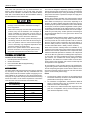
1
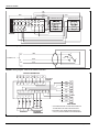
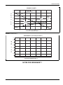
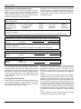
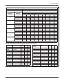
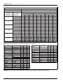
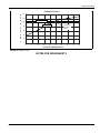
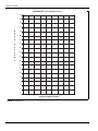
ACCESSORY KIT INSTALLATION MANUAL
DUAL FUEL CONTROL KIT 3024-7481/F
FOR USE WITH MODELS: BRHS, BRHQ, DRHS, DRHQ, ERHS, ERHQ, THGD, GHGD, YHJD, CHJD, LHJD
THERMOSTAT
3024-7481/F CONTROL
FURNACE
HEAT PUMP
FIGURE 1: BRHS, BRHQ, DRHS, DRHQ, ERHS, ERHQ
THERMOSTAT
3024-7481/F CONTROL
FURNACE
HEAT PUMP
FIGURE 2: THGD, GHGD, YHJD, CHJD, LHJD
SAFETY
IMPORTANT - These instructions are intended for the use of
qualified individuals specially trained and experienced in installation of this type of equipment and related system components.
Installation and service personnel are required by some states
to be licensed.
Persons not qualified shall not install this equipment or interpret
these instructions.
NOTE: The words “Shall” or “Must” indicate a requirement
which is essential to satisfactory and safe product performance.
The words “Should” or “May” indicate a recommendation or
advice which is not essential and not required but which may be
useful or helpful.
Installation and service personnel are required by some states
to be licensed.
Persons not qualified shall not install this equipment or interpret
these instructions.
The installer should comply with all local codes and regulations
which govern the installation of this type of equipment.
Improper installation may damage equipment, can create a shock hazard, and will void the warranty.
Johnson Controls Unitary Products
18630-UAI-E-0808
18630-UAI-E-0808
Local codes take precedent over any recommendations contained in these instructions. In lieu of local codes, the equipment should be installed in accordance with National Electric
Code and in accordance with the recommendations made by
the National Board of Fire Underwriters.
FIRE HAZARD – Failure to observe the following
warnings could cause furnace malfunction resulting in
fire or asphyxiation.
1. When indoor heat pump coils are used with fuel burning
furnaces, they must be installed in the discharged air
stream. Installation of a heat pump coil in the return air
stream of a fuel burning furnace could cause excessive
heat exchanger corrosion and burner malfunction.
2. No attempt shall be made to operate the heat pump in
the heating mode at the same time the fuel burning furnace is in operation. Failure to observe this warning will
result in abnormally high refrigerant temperatures and
pressures resulting in system failure.
Ground unit to prevent electric shock. Before making
electrical connections or servicing the system, disconnect power to both the indoor and the outdoor units.
GENERAL INFROMATION
Contents of this Package are:
1.
Heat Pump Dual Fuel Control Box
2.
Outdoor Thermostat
3.
User’s Information Manual (Supplementary)
4.
Installation Instructions
APPLICATION
The 3024-7481/F heat pump dual fuel control may be used with
any heat pump in conjunction with any residential fossil fuel
burning furnace that has a blower capable of supplying air volumes suitable for air conditioning. It may also be used with any
heat pump in conjunction with any UPG manufactured housing
furnace. See Table 1 for air volume requirements. The furnace
must also have a 40 VA transformer and a blower relay.
2
Nominal Tons of
Air Conditioning
Air Volume CFM
1-1/2
600
2
800
2-1/2
1000
3
1200
3-1/2
1400
4
1600
5
1800
The control is designed to separately operate the heating systems of the heat pump and the furnace. The only time that both
will operate simultaneously is during the defrosting of the heat
pump where the furnace is operated to temper the supply air to
the conditioned space.
During normal heating operation the wall thermostat controls
the temperature of the home. The outdoor thermostat is used to
select either the heat pump or the furnace, depending on its
set-point. At outdoor ambient temperature above the set-point,
the heat pump will operate to maintain the home comfort. Below
the set-point, the furnace operates. Regardless of which system
is operating, the first stage of the wall thermostat is normally in
control (unless the home loses heat faster than can be compensated for by the heat pump, at which point the second stage of
the wall thermostat will turn on the gas furnace until the first
stage is satisfied).
If the wall thermostat selection switch is placed in "Emergency
Heat" position, or during a heat pump "Safety Lockout" the furnace will provide all heat. Normal operation will be resumed
when the "System" switch is returned to the "Heat" position, or
when the Safety Lockout" is reset (see heat pump instructions
for further information about a "Safety Lockout" condition).
Read these instruction carefully before the installation of any
component of the heat pump system. Where these instructions
differ from the instruction packed with other components, these
instructions shall take precedence. Otherwise, use components
that do not differ as a guide line for installing those components.
In most cases, the control package should not be retrofitted to
gun furnaces; use a 3024C7473 control package for these
applications. The 3024C7473 control includes a 40 VA transformer, blower motor terminals, and a blower control relay that
are required for such applications.
Do not install any coil to a furnace which is to be operated during the heating season without attaching the refrigerant lines to
the coil and opening the system service valves. Failure to do so
will cause excessive pressures within the coil that could damage the coil and cause personal injury.
NOTE:
1.
The heat pump outdoor unit, indoor coil, and refrigerant line
set must be matched up as shown in the tabular data sheet
packed with the heat pump outdoor unit.
2.
For horizontal coil applications, field fabricated blank-off
plates or transition plenum may be required to fit the coil
cabinet to the furnace outlet flanges.
3.
Amp. draw for the wall thermostat's first stage heat anticipator is a non-adjustable .6 amp. The second stage anticipator should be adjusted to .3 amp.
Johnson Controls Unitary Products
18630-UAI-E-0808
INSTALLATION ON GAS OR OIL FURNACE
SHOCK HAZARD - Disconnect electric power to
equipment before installation to prevent equipment
damage and possible personal injury.
The furnace must have a blower capable of delivering the air
volume specified in Table 1 and be air conditioning ready.
Install heat pump coil and cabinet onto the outlet of the furnace.
See instruction packed with these components. Route the
refrigerant lines from the outdoor heat pump unit to the indoor
heat pump coil per the instructions packed with the heat pump.
Mount the 3024-7481/F control box on the outside of the furnace casing or on a wall near the furnace. The control box may
be located outside directly on certain outside gas furnaces. The
location and installation must conform to approved electrical
codes. If the furnace does not have a 40 VA (or larger) transformer, and an A/C blower relay, those items must be installed
at this time.
Low voltage control wiring to the furnace, wall thermostat, outdoor heat pump unit, and 3024-7481/F control box should be
connected per Figures 1, 2, and 3.
Installation of Outdoor Thermostat
Location
The outdoor thermostat is designed to be installed in an outdoor
environment. However, constant shade is the determining factor in selecting a location for the outdoor thermostat. Radiant
heat from direct rays of the sun could affect the operation of the
thermostat.
There may be some heat pump models that provide an attachment location for the outdoor thermostat, most models do not.
Careful selection should be used in locating the outdoor thermostat. The electric cable provided is long enough to allow the
thermostat to be mounted on a nearby structure.
Wiring
Remove the cover from the heat pump control box. Route the
end of the cable through the grommet and into the low voltage
box. Connect cable to the correct terminations. See Figure 3.
Coil and neatly tie excess cable. Replace cover in unit control
box and set outdoor thermostat.
Setting the Outdoor Thermostat
IMPORTANT - The outdoor thermostat should not set lower
than the application balance point temperature. It is permissible
to set the outdoor thermostat above this temperature if it is economically beneficial.
Johnson Controls Unitary Products
Determining the application balance point:
Before setting the outdoor thermostat, a heat loss calculation
must be made of the home. The heat loss of a home is
assumed to be linear and inversely proportionate to the outdoor
temperature. As the outdoor temperature drops, the heat loss of
the home increases. Conversely, the heat pump capacity is
reduced as the outdoor temperature drops. At some outdoor
temperature, heat pump capacity will balance with the home
heat loss.
In other words, at the temperature, the heat loss of the home
will be identical to the amount of heat produced by the heat
pump.
In order to determine the exact temperature, it is necessary to
chart the heat loss against the capacity of the heat pump. See
the heat pump application data for the capacity information at
various outdoor temperatures. Chart the capacities of the heat
pump at the corresponding outdoor temperatures on a graph
and connect the points. See Figure 4 “Example Chart 1”. The
vertical axis represents BTU per hour (in thousands) and the
horizontal axis represents outdoor temperature.
For this example, the heating performance data for 024 model
is shown as Figure 6 and was obtained from the Technical
Guide for 018 models thru 060 13 SEER R-22 Split System
Heat Pump. First, the outdoor unit is matched to an indoor coil
and the corresponding multipliers are selected; for this example, MH30S is selected as shown.
In addition, assume air entering the indoor coil is 70ºF (temperature at which the room is to be maintained) and indoor CFM is
600. Then plot BTU per hour against outdoor temperature as
shown with diamond symbol. Draw a straight line that best fits
all the points.
For instance, for 47°F outdoor air, the “BTUH x 1000” value
would be:
Thousand British
Thermal Units per Hour
(MBTUH) value at 47°F
Outdoor and 70°F indoor
X
MH30S coil multiplier
for Thousand British
Thermal Units per
Hour (MBH)
= 22.3 x 1.0 = 22.3 BTUH x 1000.
In addition, for the purpose of this example, assume that the
calculated heat loss of the home is 50,800 BTU’s per hour at an
outdoor design temperature of + 10º F. Moving up the vertical
axis, at + 10º F, locate the number of BTU’s per hour heat loss
and mark that point on the graph. Placing a straight edge on
this point, and aligning with the 70º F, (the normal indoor comfort condition) in the lower right-hand corner, connect these two
points with a straight line. Locate the point at which the heat
loss crosses the capacity curve of the heat pump. This intersection is the application balance point temperature for the example application.
3
18630-UAI-E-0808
YEL
YEL
YEL
BLK
RED
WHT
GRN
R
Y
G
W2
S2
S1
DEFROST RELAY
A
B
FURNACE RELAY
A
B
7
4
Y
5
9
WHT
ORG
1
4
1
7
8
5
8
3
9
3
FIGURE 3: Wiring Diagram - 3024-7481/F Heat Pump Dual Fuel Control Kit
S2
CONNECT TO
B
GRN
2
RED
1
3
WHT
W2
FIGURE 4: Wiring Diagram - 3024-671/F Outdoor Thermostat
INDOOR THERMOSTAT
B
O
L
X
W2
R
Y
G
3024-7481/F
CONTROL
B
O
L
X
W2
R
Y
G
RED
R
ORG
O
PUR
B
O
R
C
L
W
X
E
W2
S2
S1
BLK
Y
GRN
WHT
RED
GRN
WHT
BLU
RED
C
W
FURNACE
Y
BRN
G
OUTDOOR
THERMOSTAT
*
WHT
+*
GRY
W1/66
W
CC
HEAT PUMP
*
R
C
YEL
G
X/L
THIS WIRE MUST BE CLOSED WITH WIRE NUT
TO PREVENT ELECTRICAL MALFUNCTION.
+ THIS GREY (GRY) WIRE FROM CONTACTOR
COIL (CC) IS NOT PRESENT IN SOME MODELS.
FIGURE 5: Wiring Connections
4
Johnson Controls Unitary Products
18630-UAI-E-0808
EXAMPLE CHART 1
70
DESIGN
TEMPERATURE
60
B
T
U
H
50
40
1
0
0
0
APPLICATION
BALANCE POINT
HEAT
LOSS
X
30
HEAT
PUMP
CAPACITY
ECONOMIC
BALANCE
POINT
20
10
0
0
10
20
30
40
50
60
70
60
70
OUTDOOR TEMPERATURE °F
FIGURE 6: Example Chart 1
WORKSHEET 1 (For Example Chart 1)
70
60
B
T
U
H
50
40
X
1
0
0
0
30
20
10
0
0
10
20
30
40
50
OUTDOOR TEMPERATURE °F
FIGURE 7: Worksheet 1
NOTES FOR WORKSHEET 1
Johnson Controls Unitary Products
5
18630-UAI-E-0808
Determining the economical balance point:
Determine the cost of electricity, price and type of furnace fuel
(natural gas, propane, or heating oil), and efficiency of furnace.
For the purpose of this example, assume cost of electricity is
$0.10 per KWh, cost of natural gas is $0.84 per therm, and furnace efficiency is 90%.
The KW values from the same heat pump application data of
Figure 6 is used for this section and the result is plotted as
shown with triangle symbol in Figure 7 “Example Chart 2”. The
vertical axis represents BTU (in thousands) per dollar and the
horizontal axis represents outdoor temperature.
For electricity calculation, plot BTU per $ against outdoor temperature. For instance, for 40°F outdoor air, the “BTU x 1000
per $” value would be:
Thousand British
MH30S coil multiplier
Kilowatt (KW)
Cost of
MH30S coil
Thermal Units per
for Thousand British
at 47°F
multiplier for
Hour (MBTUH) value
X Thermal Units per
³ electricity ³ value
³
Outdoor and
($/KWh)
Kilowatt (KW)
at 47°F Outdoor and
Hour (MBH)
70°F indoor
70°F indoor
= 19.3 x 1.0 x (1 / 0.10) x (1 / 1.8) x (1 /1.0)
= 107 BTU x 1000 per $.
This value is the amount of heat the heat pump provides for each dollar spent for electricity to operate the heat pump.
For the furnace fuel calculation, plot the BTU per $ against outdoor temperature. This is usually a linear horizontal line. For instance, for the natural gas example, the “BTU x 1000 per $” value would be:
Furnace
Efficiency
³
Cost of natural
gas ($/therm)
100000 BTU*
X
1 therm
1
X
1000
= 0.9 x (1 / 0.84) x (100000 / 1) x (1 / 1000)
= 107 BTU x 1000 per $.
This value is the amount of heat the furnace provides for each dollar spent for natural gas.
If using heating oil furnace, then apply:
Furnace
Efficiency
³
Cost of heating
oil ($/gal)
X
139000 BTU*
1 gal
X
1
1000
If using propane furnace, then apply:
Furnace
Efficiency
³
Cost of
propane ($/gal)
X
916000 BTU*
These plots represent the fuel and electrical costs. Where these
two costs intersect is the economical balance point. It is where
$1.00 will purchase the same amount of BTU’s from either the
heat pump or the furnace. Mark the economic balance point for
later reference. In summary, this application example shows an
economic balance point of 40º F for a 13 SEER heat pump and
a 90% natural gas furnace using $0.10/KW electricity and
$0.84/therm. gas.
Adjusting Thermostat Set Point
On the chart that you determined the application balance point
for your particular application as shown in Figure 4. Mark and
label the economical balance point temperature on the curve
representing the heat loss of the structure.
1 gal
X
1
1000
Remove the outdoor thermostat cover. The thermostat is factory set at 30º F. It should be adjusted to the higher of the two
temperatures marked on “heat loss” curve whether it be the
application or economical balance point. Adjust by turning the
slot on the thermostat shaft to align with the new temperature
setting.
Should the economic balance point be lower than the application balance point, and the outdoor thermostat is set to this temperature, the control will operate the heat pump until the home
temperature drops to close the second stage of the wall thermostat, at which time the heat pump will be turned off and the furnace will operate. Under this condition, the furnace will continue
to operate until the home temperature rises to satisfy the first
stage. When the first stage of the wall thermostat closes again,
the control will operate the heat pump and the cycle will repeat
to maintain the home comfort. Replace the outdoor thermostat
cover.
Energy conversion Factor for furnace fuels (propane, heating
oil, natural gas) changes with every batch of fuel.
6
Johnson Controls Unitary Products
18630-UAI-E-0808
HEATING PERFORMANCE DATA
CONDENSING UNIT MODEL NO
ERHS0241BA
EVAPORATOR COIL MODEL NO
FC/MC/PC/UC24
AIR TEMP.
ENTERING
OUTDOOR UNIT
AIR TEMP.
ENTERING
INDOOR COIL
60
47
40
30
17
10
ID CFM
600
800
1000
MBTUH
KW
C.O.P.
MBTUH
KW
C.O.P.
MBTUH
KW
C.O.P.
60
26.5
2.1
3.7
21.7
0.7
8.8
25.5
1.9
3.9
70
25.6
2.1
3.5
20.7
1.1
6.3
25.4
2.0
3.7
80
24.6
2.2
3.3
19.7
1.6
3.7
25.2
2.1
3.5
60
23.4
1.8
3.7
18.4
1.3
4.1
22.4
1.7
3.8
70
22.3
1.9
3.5
17.3
1.0
5.6
22.3
1.8
3.6
80
21.1
1.9
3.2
16.3
0.7
7.0
22.2
1.9
3.5
60
20.4
1.7
3.5
16.4
1.2
3.9
20.7
1.6
3.7
70
19.3
1.8
3.2
15.3
1.3
3.5
20.4
1.7
3.5
80
18.2
1.8
2.9
14.1
1.3
3.1
20.2
1.8
3.4
60
18.8
1.6
3.4
13.8
1.2
3.4
19.0
1.5
3.6
70
16.9
1.6
3.0
12.7
1.2
3.1
17.8
1.6
3.3
80
15.0
1.7
2.6
11.7
1.2
2.8
16.6
1.6
3.0
60
13.3
1.5
2.6
10.0
1.1
2.6
15.3
1.4
3.1
70
11.4
1.5
2.2
9.0
1.1
2.3
13.0
1.5
2.6
80
9.5
1.6
1.8
8.0
1.2
2.0
10.8
1.5
2.0
60
12.0
1.5
2.4
8.9
1.1
2.3
11.8
1.4
2.5
70
9.6
1.5
1.9
8.0
1.1
2.1
10.0
1.5
2.0
80
7.2
1.6
1.4
7.0
1.2
1.8
8.2
1.5
1.6
NOTE: ALL CAPACITIES ARE NET WITH INDOOR FAN HEAT ALREADY DEDUCTED AT 1250 BTUH/1000 CFM.
Multipliers for determining the performance with other indoor sections.
Air Handler
Coil
MBH
KW
COP
MA08B
FC/MC24B
1.00
1.00
1.00
MA08B
FC/MC30B
1.00
1.00
1.00
MA08B
FC/MC36B
1.00
1.00
1.00
AHP24
–
1.00
1.00
1.00
F*FP030
–
1.00
1.00
1.00
MV12B
FC/MC24B
0.97
0.93
0.90
MV12B
FC/MC30B
0.97
0.93
0.90
AV24
–
0.97
0.93
0.90
–
FC/MC/PC/UC30
1.00
1.00
1.00
–
FC/MC/PC/UC36
1.00
1.00
1.00
–
HC30
1.00
1.01
1.01
–
HD24
1.00
1.00
1.00
–
MH30S
1.00
1.00
1.00
Variable Speed
Coil
Furnace
MBH
KW
COP
(F,L)C8VA12
FC/MC/PC24A
0.97
0.96
0.93
FC9VA12
FC/MC/PC24A
0.97
0.96
0.93
FC9(C,V)B12
FC/MC/PC24B
0.97
0.96
0.93
(F,L)C8VA12
FC/MC/PC30A
0.97
0.96
0.93
FC9VA12
FC/MC/PC30A
0.97
0.96
0.93
FC9(C,V)B12
FC/MC/PC30B
0.97
0.96
0.93
(F,L)C8VA12
FC/MC/PC36A
0.97
0.96
0.93
FC9VA12
FC/MC/PC36A
0.97
0.96
0.93
FC9(C,V)B12
FC/MC/PC36B
0.97
0.96
0.93
(F,L)C8VA12
HC30
1.00
1.01
1.01
FC9VA12
HC30
1.00
1.01
1.01
(F,L)C8VA12
HD30
0.97
0.96
0.93
FC9VA12
HD30
0.97
0.96
0.93
FIGURE 8: ERHS024 Extract from Technical Guide for ERHS018 thru 060 13 SEER R-22 Split System Heat Pump
Johnson Controls Unitary Products
7
18630-UAI-E-0808
HEATING PERFORMANCE DATA
CONDENSING UNIT MODEL NO
THGD24S21S1
EVAPORATOR COIL MODEL NO
AHP24
AIR TEMP.
ENTERING
OUTDOOR UNIT
60
47
40
30
17
10
AIR TEMP.
ENTERING
INDOOR COIL
ID CFM
600
800
1000
MBTUH
KW
C.O.P.
MBTUH
KW
C.O.P.
MBTUH
KW
C.O.P.
60
25.6
4.23
1.77
26.9
4.47
1.76
28.3
4.70
1.76
70
24.4
4.09
1.75
25.8
4.41
1.71
27.3
4.75
1.68
80
23.2
3.95
1.72
24.7
4.35
1.66
26.2
4.79
1.60
60
21.8
4.46
1.43
23.1
4.90
1.38
24.3
5.35
1.33
70
20.6
4.03
1.51
21.9
4.20
1.56
23.2
4.40
1.61
80
19.4
3.59
1.58
20.7
3.50
1.73
22.1
3.44
1.88
60
19.5
4.10
1.39
20.8
4.54
1.34
22.0
4.99
1.29
70
18.6
3.76
1.46
19.8
4.12
1.42
21.0
4.49
1.38
80
17.7
3.41
1.52
18.8
3.69
1.49
19.9
3.99
1.46
60
17.3
3.95
1.28
18.0
4.15
1.27
18.7
4.34
1.26
70
16.0
3.54
1.33
16.8
3.73
1.33
17.6
3.93
1.32
80
14.7
3.12
1.38
15.6
3.31
1.38
16.5
3.52
1.37
60
12.8
2.71
1.38
13.5
3.16
1.25
14.1
3.68
1.12
70
11.7
2.67
1.28
12.4
2.98
1.21
13.0
3.33
1.14
80
10.6
2.63
1.18
11.2
2.80
1.17
11.8
2.97
1.16
60
9.5
2.67
1.04
10.7
2.92
1.07
11.9
3.16
1.10
70
9.2
2.50
1.08
10.1
2.71
1.09
10.9
2.91
1.10
80
8.9
2.32
1.12
9.4
2.50
1.10
9.9
2.66
1.09
NOTE: ALL CAPACITIES ARE NET (KBTUH) WITH INDOOR FAN HEAT ALREADY DEDUCTED AT 1250 BTUH/1000 CFM.
Multipliers for determining the performance with other indoor sections.
Air Handler
–
–
–
–
–
–
–
–
–
AHP30
AV24
FPFP030
MV12B
MA08B
MV12B
MA08B
MV12B
MA08B
Coil
FC/MC/PC/UC24
FC/MC/PC/UC30
FC/MC/PC/UC32
FC/MC/PC/UC35
HC30
HC36
HD24
MH24S
MH30S
–
–
–
FC/MC24B
FC/MC24B
FC/MC30B
FC/MC30B
FC/MC35B
FC/MC35B
MBH
1.00
1.00
1.00
1.00
1.00
1.00
1.00
1.00
1.00
1.00
0.97
1.00
0.98
1.00
0.98
1.00
0.97
1.00
KW
1.00
1.00
1.00
1.00
1.00
1.00
1.00
1.00
1.00
1.00
1.08
1.00
1.07
1.00
1.07
1.00
1.07
1.00
COP
1.00
1.00
1.00
1.00
1.00
1.00
1.00
1.00
1.00
1.00
0.92
1.00
0.93
1.00
0.93
1.00
0.93
1.00
Variable Speed
Furnace
PV8*A12
PV9*A12
P(C,V)9*B12
PV8*A12
PV9*A12
P(C,V)9*B12
PV8*A12
PV9*A12
P(C,V)9*B12
PV8*A12
PV9*A12
P(C,V)9*B12
Coil
MBH
KW
COP
FC/MC/PC/UC24A
FC/MC/PC/UC24A
FC/MC/PC/UC24B
FC/MC/PC/UC30A
FC/MC/PC/UC30A
FC/MC/PC/UC30B
FC/MC/PC/UC32A
FC/MC/PC/UC32A
FC/MC/PC/UC35B
HC30
HC30
HC36
0.98
0.98
0.98
0.98
0.98
0.98
0.98
0.98
0.98
0.98
0.98
0.98
1.05
1.04
1.05
1.05
1.05
1.05
1.05
1.05
1.05
1.05
1.05
1.05
0.95
0.96
0.95
0.95
0.95
0.95
0.95
0.95
0.95
0.95
0.95
0.95
FIGURE 9: THGD24 Extract from Technical Guide for THGD24 thru 60 13 SEER R-22 Split System Heat Pump
8
Johnson Controls Unitary Products
18630-UAI-E-0808
EXAMPLE CHART 2
B
T
U
H
X
140
120
1
0
0
0
80
P
E
R
40
$
FURNACE FUEL
100
ELECTRICITY
ECONOMIC
BALANCE
POINT
60
20
0
-10
0
10
20
30
40
50
60
70
80
OUTDOOR TEMPERATURE °F
FIGURE 10: Example Chart 2
NOTES FOR WORKSHEET 2
Johnson Controls Unitary Products
9
18630-UAI-E-0808
WORKSHEET 2 (For Example Chart 2)
380
360
340
320
B
T
U
H
300
280
X
260
1
0
0
0
240
P
E
R
$
220
200
180
160
140
120
100
80
60
40
20
0
-10
0
10
20
30
40
50
60
70
80
OUTDOOR TEMPERATURE °F
FIGURE 11: Worksheet 2
10
Johnson Controls Unitary Products
18630-UAI-E-0808
SYSTEM OPERATIONAL CHECK-OUT
NOTE: If a programmable wall thermostat is used on this application, there will be a five minute delay when the system is
powered up for the first time, and if the system switch is moved
to another mode. See instructions packed with the thermostat.
1.
Make sure all service disconnects are open.
2.
Set thermostat switches as follows:
a.
b.
Fan switch to “Auto”.
System switch to “Off”.
14. Turn wall thermostat system switch to “Heat”.
a.
b.
c.
d.
e.
f.
g.
Emergency heat light should turn off.
Auxiliary light should remain on.
Furnace should continue to operate.
Furnace blower should operate.
Outdoor unit compressor should not operate.
Outdoor unit fan should not operate.
Warm air should continue to flow from the registers.
15. Set outdoor thermostat below outdoor temperature.
3.
Close disconnect to heat pump outdoor unit.
4.
Close disconnect to furnace.
5.
Turn thermostat fan switch to “On”. Blower should operate.
6.
Turn fan switch back to “Auto”. Blower should stop within
90 seconds.
7.
Turn system switch to “Cool” and set thermostat temperature setting below room temperature
16. Reset outdoor thermostat to its operating temperature
(see: Setting the Outdoor Thermostat).
a.
b.
c.
d.
17. Set system switch to desired mode and adjust temperature
lever to desired temperature if everything checks out correctly.
Outdoor unit compressor should operate.
Outdoor unit fan should operate.
Furnace blower should operate.
Cool air should flow from registers after system has
operated for a few minutes.
8.
Turn system switch to “Off” and wait 5 minutes.
9.
Turn system switch to “Heat” and set thermostat setting
above room temperature just enough to close the first
stage. Set the outdoor thermostat above the outdoor temperature.
a.
b.
c.
d.
Outdoor unit compressor should operate.
Outdoor unit fan should operate.
Furnace blower should operate.
Warm air should flow from registers after the system
has operated for a few minutes.
10. Set thermostat to higher temperature to close the second
stage.
a.
b.
c.
d.
e.
Outdoor unit compressor should not operate.
Outdoor unit fan should not operate.
Furnace should operate.
Furnace blower should operate.
Warm air should flow from the registers after a few
minutes.
11. Set thermostat to lower temperature to insure heating system cycles off.
12. Turn wall thermostat system switch to “Emergency Heat”.
Emergency heat light should turn on, but nothing should
operate.
13. 13. Set thermostat to higher temperature to close the second stage.
a.
b.
c.
d.
e.
a.
b.
c.
d.
e.
Furnace should stop operating.
Furnace blower should operate.
Outdoor unit compressor should operate.
Outdoor unit fan should operate.
Warm air should continue to flow from the registers.
NOTE: In the heating mode the indoor wall thermostat controls
the system operation to maintain the selected temperature,
operating either the heat pump or the furnace to do so. The
selection of either is controlled by the outdoor thermostat, i.e. at
temperatures above the setting, the heat pump operates in
response to the first stage of the wall thermostat, at temperatures below the setting of the outdoor thermostat the furnace
operates (also see the outdoor thermostat installation).
Exceptions to the above:
A.
If the heat pump fails to operate in the heating mode due to
high refrigerant pressure or temperature, the furnace will
operate regardless of the status of the outdoor thermostat.
B.
If the system switch of the wall thermostat is placed in “Emergency Heat” position, only the furnace will operate.
C.
If a defrost cycle is initiated by the heat pump, both the heat
pump and the furnace will operate until the defrost cycle is
completed.
NOTE: In both A and B above, the furnace operation is controlled by the second stage of the wall thermostat. During the
defrost cycle the furnace is controlled by the first stage.
NOTE: The heat pump has a safety lockout that will keep it
from operating if some fault causes the high temperature or the
high pressure limit switches to open. To reset the lockout, turn
the indoor thermostat system to “Off”, then back to the selected
mode within 5 seconds or disconnect the power to the transformer for at least two seconds. The heat pump will now operate. Should a lockout re--occur, then the cause of the lockout
should be sought and corrected immediately.
Emergency light should be on.
Auxiliary heat light should turn on.
Furnace should operate.
Furnace blower should operate.
Warm air should flow from the registers after a few
minutes.
Johnson Controls Unitary Products
11
NOTES
Subject to change without notice. Printed in U.S.A.
Copyright © 2008 by Johnson Controls, Inc. All rights reserved.
Johnson Controls Unitary Products
5005 York Drive
Norman, OK 73069
18630-UAI-E-0808
Supersedes: 18630-UAI-D-0108