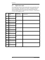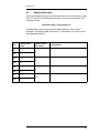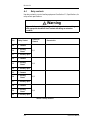
1
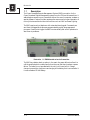
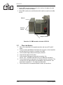
Remote Management System
For
FMX Transmitters
User’s Manual
©2002 Crown Broadcast, a division of International Radio and Electronics, Inc.
25166 Leer Drive, Elkhart, Indiana, 46514-5425 U.S.A.
(574) 262-8900
Revision Control
Revision
Print Date
Revision 2.0
March 2005
Important Notices
©2002 International Radio and Electronics, Inc.
All rights reserved. No part of this publication may be reproduced, transmitted,
transcribed, stored in a retrieval system, or translated into any language in any form
by any means without the written permission of IREC, Inc.
Printed in U.S.A.
IREC attempts to provide information that is accurate, complete, and useful.
Should you find inadequacies in the text, please send your comments to the
following address:
International Radio and Electronics
25166 Leer Drive, P.O. Box 2000
Elkhart, Indiana, 46515-2000 U.S.A.
ii
RMS User’s Manual
Revision 2.0
Table of Contents
Section 1—Getting Acquainted
1.1 Description ..................................................................................................1-2
1.2 Specifications ..............................................................................................1-3
1.3 Safety Considerations ..................................................................................1-4
1.3.1 Dangers...................................................................................................1-4
1.3.2 Warnings.................................................................................................1-4
1.3.3 Cautions ..................................................................................................1-4
Section 2—Installation
2.1 Before You Install ........................................................................................2-2
2.1.1 System Connections................................................................................2-2
2.1.2 Controls and Indicators ...........................................................................2-3
2.1.3 Auxiliary Equipment Connections............................................................2-4
2.2 Installing the RMS .......................................................................................2-5
2.2.1 Installing RMS module on FMX30 transmitter ........................................2-5
2.2.2 Installing RMS module on FMX100 and FMX250 transmitters................2-7
2.3 Place into Service ........................................................................................2-8
Section 3—Operation
3.1 Introduction .................................................................................................3-2
3.2 Call In System Monitoring ...........................................................................3-2
3.3 Automatic Call out .......................................................................................3-4
3.4 Remote Control Commands ........................................................................3-5
3.4.1 Remote Power and Frequency Commands..............................................3-5
3.4.2 FMX/RMS Audio Monitoring ...................................................................3-6
3.4.3 Relay Commands ....................................................................................3-7
Section 4—Service and Support
4.1 Service.........................................................................................................4-2
4.2 24–Hour Support.........................................................................................4-2
4.3 Spare Parts..................................................................................................4-2
Appendix A—Pin Assignment Worksheet
A.1
A.2
A.3
A.4
DC power supply .........................................................................................A-1
Digital status inputs.....................................................................................A-2
Analog status input......................................................................................A-3
Relay contacts .............................................................................................A-4
iii
Revision 2.0
iv
RMS User’s Manual
Revision 2.0
I
INFORMATION
Section 1—Getting Acquainted
This section provides a general description of the Crown
Broadcast Remote Management System and introduces you to
safety conventions used within this document. Review this
material before installing or operating the equipment
Getting Acquainted
1—1
I
Revision 2.0
1.1
Description
The Crown Broadcast Remote Management System (RMS) is an option for the
Crown Broadcast Digital Management system found on FMX series transmitters. It
adds telephone access to your transmitter without the use of a computer, modem or
special software. Features include remote performance monitoring and operation of
not only the transmitter but also site functions such as HVAC and tower lighting.
The RMS requires only a telephone with a standard tone keypad. Commands are
sent from the keypad and responses are generated by a plain language speech
processor. Preset limits trigger the RMS to automatically dial control operators to
alert them to problems.
Illustration 1-1 RMS Mounted on back of transmitter
The RMS has a battery back-up option in the event of a power failure to allow it to
call the specified phone numbers and inform the user that there has been a power
failure. The battery is not provided with the unit, but it has a built-in 3 stage
charger to prevent any long term overcharging of the battery that is connected to it.
It uses a standard 12 volt battery.
1—2
RMS User’s Manual
Revision 2.0
1.2
Specifications
System Compatibility
Crown FMX30, FMX100 and FMX250 series
transmitters.
Telephone Access
Dial-up telephone line by dual-tone, multifrequency keypad.
AC Power
120-240 Volts AC from external power supply,
50-60 Hz
Backup Battery
+12 volts DC from user supplied battery. RMS
maintains battery charge.
Digital Status Input
Eight digital inputs to monitor external
equipment status.
+5 Volt d.c. = High state
0 Volt d.c. = Low state
Analog Status Input
Four analog inputs to monitor external
equipment status.
-12 to +12 Volt DC
Relay Output
Four sets of SPDT relay contacts
Current limited to 500 mA at 100 volts DC
Auxiliary Power Output
5 volts DC, current limited to 500 mA
Getting Acquainted
1—3
I
Revision 2.0
1.3
Safety Considerations
Crown Broadcast assumes the responsibility for providing you a safe product and
safety guidelines during its use. “Safety” means protection to all individuals who
install, operate, and service the RMS module as well as protection of the RMS
module itself. To promote safety, we use standard hazard alert labeling on the
product and in this manual. Follow the associated guidelines to avoid potential
hazard.
1.3.1
Dangers
DANGER represents the most severe hazard alert. Extreme bodily harm or death
will occur if DANGER guidelines are not followed.
1.3.2
Warnings
WARNING represents hazards which could result in severe injury or death.
1.3.3
Cautions
CAUTION indicates potential personal injury, or equipment or property damage if
the associated guidelines are not followed. Particular cautions in this text also
indicate unauthorized radio-frequency operation.
Pictorial or
written
description
of hazard
DANGER
Severity of
hazard
Sever shock hazard!
Turn power off and wait
approximately 1 minute for
capacitors to discharge before
handling them.
Explanation of
hazard
Illustration 1–2 Hazard Warning
1—4
RMS User’s Manual
fi
Section 2—Installation
This section provides important guidelines for installing your
Remote Management System. Review this information carefully
for proper installation.
Installation
2—1
Revision 2.0
2.1
Before You Install
Before you begin installing the RMS, take time to review the following connector
information:
• Section 2.1.1, System Connections
• Section 2.1.2, Controls and Indicators
• Section 2.1.3, Auxiliary Equipment Connections
2.1.1
System Connections
System connections are required connections for RMS operation.
Telephone
Connections
Transmitter
Remote I/O
Power
Connector
System
Ground
Audio Monitor
Illustration 2-1 RMS Controls and Connectors
Telephone Connections Standard RJ-11 telephone connection. Connect to dial-up
telephone line. Use one jack for the line and the other jack for monitoring the line.
The jacks are wired in parallel and not switched.
Transmitter Remote I/O Connections to transmitter Remote I/O connector.
Power Connector Connect to AC supply and optional battery
Audio Monitor A pass through connection to monitor an audio source.
System Ground Connect to station system ground.
2—2
RMS User’s Manual
Revision 2.0
2.1.2
Controls and Indicators
Analog Gain
Status Indicators
Illustration 2-2 RMS Controls and Connectors
Analog Gain Use to trim the analog input.
Status Indicators A display of conditions and states of the RMS.
A
Heartbeat
The RMS processor is functioning normally. The
heartbeat LED will flash about once per second.
B
Call-out state
When illuminated, the RMS is placing a call
C
Call-in state
When illuminated, the RMS is in the call-in state
D
Traffic
The RMS is processing a remote command.
Installation
2—3
Revision 2.0
2.1.3
Auxiliary Equipment Connections
Connections between the RMS and auxiliary equipment are made at a row of
removable connector blocks.
DC Out
Digital Status
Inputs
Analog Status
Inputs
Relay
Contacts
Position 1-4
Position 5-20
Position 21-28
Position 29-40
Illustration 2-3 RMS Controls and Connectors
DC Out A DC power supply for auxiliary relays. Output is +5 volts DC and current
limited by an internal circuit breaker.
Digital Status Inputs Eight digit status input to monitor external equipment. Input
level is 0 to +5 volts DC. Current limited by internal circuit breaker. See
Section A.2, Digital status inputs, for connector assignments an command
channels.
Analog Status Inputs Four analog inputs. Input range is -12 to +12 volts. Current
limited by internal circuit breaker. See Section A.3, Analog status input, for
connector assignments and command channels.
Relay Contacts Four sets of SPDT relay contacts. Maximum voltage is 200 volts DC
and current limited by internal circuit breaker. See Section A.4, Relay contacts, for
connector assignments and command channels.
Warning
If you switch or control high voltage with the relay contacts, use wiring
with appropriate insulation. Avoid contact with wiring on connector
contacts.
2—4
RMS User’s Manual
Revision 2.0
2.2
Installing the RMS
Installation procedures vary with the model on which you are installing the RMS.
Choose the appropriate procedure.
FMX30
The RMS mounts directly to the back of the transmitter.
FMX100 and FMX250 The RMS mounts to an additional adaptor bracket.
2.2.1
Installing RMS module on FMX30 transmitter
Follow the transmitter shut down procedures. Note the position of cables before
disconnecting cables on the back of the transmitter and remove the transmitter
from the operating location.
1.
Remove power amplifier access cover and hole plug.
Power amplifier
access cover
Hole plug
Illustration 2-4
2.
Position RMS mounting bracket over the four holes with captive nuts. (Two
of the holes attached the power amplifier access cover. Fasten with machine
screws and lock washers.
Mounting screws
Mounting bracket
Illustration 2-5 FMX30 with bracket installed
Installation
2—5
Revision 2.0
3.
Position RMS module inside the mounting bracket. Replace end screws and
washers.
Module
Mounting
bracket
Machine
screws
Illustration 2-6 RMS module in mounting bracket
4.
2—6
Continue in Section 2.3, Place into Service.
RMS User’s Manual
Revision 2.0
2.2.2
Installing RMS module on FMX100 and FMX250 transmitters
Follow the transmitter shut down procedures. Note the position of cables before
disconnecting cables on the back of the transmitter and remove the transmitter
from the operating location. FMX250G is modified the same way.
1. Loosen the power amplifier mounting screws on the back of the transmitter.
Power amplifier
mounting screws
Illustration 2-7 Power amplifier mounting screws
2. Slide the RMS adaptor bracket between the power amplifier and transmitter
body.
Adaptor
bracket
Power
amplifier
Illustration 2-8 Installing FMX100 and FMX250 adaptor bracket (transmitter shown
upside down)
3. Tighten power amplifier mounting screws.
Installation
2—7
Revision 2.0
4. Position RMS mounting bracket over the four studs on the adaptor bracket.
Fasten with nuts and lock washers.
5. Fasten RMS module onto module bracket with machine screws from installation kit.
Module
Machine
screws
Adaptor bracket
Illustration 2-9 RMS mounted on the back of FMX100
2.3
1.
2.
3.
4.
5.
6.
7.
2—8
Place into Service
Return the transmitter to the operating location and connect RF and AC
power.
Connect remote cable between the Remote I/O connector on the transmitter
and the Remote I/O connector on the back of the RMS.
Connect power supply cable to power supply connector.
Plug external supply into AC power.
Connect audio to the pass through audio connectors. See
Section 3.4.2, FMX/RMS Audio Monitoring, for additional information.
Connect status inputs to equipment you choose to monitor and control. The
connectors for the status outputs are removable for easy connection. Use
worksheets in Appendix A—Pin Assignment Worksheet.
Follow instructions in transmitter manual for start up instructions.
RMS User’s Manual
Section 3—Operation
This section provides general operating parameters of your
Remote Management System and a detailed description of its
operating functions
Operation
3—1
Revision 2.0
3.1
Introduction
The RMS operates in three remote modes. Each mode is described in the following
sections.
• Section 3.2, Call In System Monitoring
• Section 3.3, Automatic Call out
• Section 3.4, Remote Control Commands
3.2
Call In System Monitoring
The RMS can monitor all system parameters with a standard telephone equipped
with a tone keypad.
Once connected to the RMS you can access the following information:
• All readings available from the transmitter front panel,
• Readings from the RMS analog inputs
• Status of all RMS digital inputs.
To to use call-in system monitoring:
1. Call the RMS and wait for the voice prompt or wait until the call-out message
is complete.
2. Press * on the telephone keypad.
3. Choose commands from Table 3-1.
Commands
Description
0 *
Channel #0, PA Volts
1 *
Channel #1, PA Current
2 *
Channel #2, RF Power
3 *
Channel #3, SWR
4 *
Channel #4, Temperature Deg C
5 *
Channel #5, PwrSupply Volts
6 *
Channel #6, ALC Level%
7 *
Channel #7, Analog In 1 Volts
8 *
Channel #8, Analog In 2 Volts
9 *
Channel #9, Analog In 3 Volts
1 0 *
Channel #10, Analog In 4 Volts
Table 3-1 Remote Monitor Commands
3—2
RMS User’s Manual
Revision 2.0
Commands
Description
1 1 *
Channel #11, Digital In 1 Hi/Lo
1 2 *
Channel #12, Digital In 2 Hi/Lo
1 3 *
Channel #13, Digital In 3 Hi/Lo
1 4 *
Channel #14, Digital In 4 Hi/Lo
1 5 *
Channel #15, Digital In 5 Hi/Lo
1 6 *
Channel #16, Digital In 6 Hi/Lo
1 7 *
Channel #17, Digital In 7 Hi/Lo
1 8 *
Channel #18, Digital In 8 Hi/Lo
1 9 *
Channel #19, Rx Signal Level TBD
2 0 *
Channel #20, AC Power Status,
#
Go to Remote Control Functions
After 30 seconds of inactivity the RMS will
hang-up.
Table 3-1 Remote Monitor Commands (Continued)
Operation
3—3
Revision 2.0
3.3
Automatic Call out
You may program the RMS to call a telephone number and give you an alarm report
when triggered by preset conditions. The alarm conditions are programmed from
the front panel of the FMX transmitter. Alarms include:
•
•
•
•
•
High VSWR
Low or loss of RF power
High power amplifier current,
High power amplifier temperature
External digital status inputs which have been set to alarm at either a high or
low state
• Analog inputs which have either a high or low limit alarm.
If any of the alarm conditions trigger the RMS, it automatically calls the pre
programmed number and gives the following voice report:
• The greeting “Hello”
• ID number of the RMS
• A description of the alarm
Once the alarm report is complete, use the remote control commands or call-in
monitoring commands to correct the condition that caused the alarm.
3—4
RMS User’s Manual
Revision 2.0
3.4
Remote Control Commands
Use the RMS remote control commands to access the FMX transmitter settings
menus as well as the external relays on the back of the RMS unit. The remote
commands are password protected to allow only authorized users access.
To enter the remote control commands:
1. Call the unit and wait for the voice prompt.
2. Press # and then enter the password. The RMS unit will wait for the password before proceeding.
3. Use the commands from the following sections to change setting in the transmitter.
• Table 3-2, Remote Power and Frequency Commands
• Table 3-3, Audio Monitoring Commands
• Table 3-4, Remote Relay Control
3.4.1
Remote Power and Frequency Commands
Commands in Table 3-2 list commands to change power and frequency settings.
Note: Because of response time, wait several seconds after each Raise RF
Power or Lower RF Power command.
Commands
Description
1
Raise RF Power Level
2
Lower RF Power Level
3
Turn RF Carrier ON
4
Turn RF Carrier OFF
6
RF Carrier Frequency Setting, MHz.
#
Hang-up
After 30 seconds of inactivity, the RMS hangs up.
Table 3-2 Remote Power and Frequency Commands
Operation
3—5
Revision 2.0
3.4.2
FMX/RMS Audio Monitoring
The RMS unit can monitor a variety of audio sources available from the FMX DMS as
well as the RMS unit.
Audio monitoring points include:
• The demodulated left or right channel from the 'on-air' tuner that is built into the
FMX transmitter.
• The left or right channel audio at the XLR inputs on the back of transmitter.
• The left or right channel audio output of the audio Processor/stereo generator
boards.
• The left or right channel audio of the external loop audio on the back of the RMS
module.
Use audio monitoring to troubleshoot audio problems over the telephone. It is also a
quick check to verify that the transmitter is producing RF power because the antenna
for the tuner is located near the RF low pass filter.
7
Audio Monitor Function
1
RMS External L + R
*
2
FMX/DMS Right Input
*
3
4
5
Return to Selection
FMX/DMS Left Processor
*
6
Return to Selection
FMX/DMS Composite Audio
*
7
Return to Selection
FMX/DMS Right Receiver
*
8
Return to Selection
FMX/DMS Left Receiver
*
3—6
Return to Selection
FMX/DMS Right Processor
*
#
Return to Selection
FMX/DMS Left Input
*
#
Return to Selection
Return to Selection
Return to Remote Control State
Hang up
RMS User’s Manual
Revision 2.0
3.4.3
Relay Commands
The following commands control the settings of the relay contacts on the back of
the RMS.
5
Output Relay Control
1
Relay 1 Control
*
Turn Relay 1 ON
#
Turn Relay 1 OFF
2
Relay 2 Control
*
Turn Relay 2 ON
#
Turn Relay 2 OFF
3
Relay 3 Control
*
Turn Relay 3 ON
#
Turn Relay 3 OFF
4
#
#
Relay 4 Control
*
Turn Relay 4 ON
#
Turn Relay 4 OFF
Return to Remote Control State
Hang-up
Table 3-4 Remote Relay Control
Operation
3—7
Revision 2.0
3—8
RMS User’s Manual
Revision 2.0
Section 4—Service and Support
We understand that you may need various levels of support or that
the product could require servicing at some point in time. This
section provides information for both of these scenarios.
Service and Support
4—1
Revision 2.0
4.1
Service
The product warranty (see opposite page) outlines our responsibility for defective
products. Before returning a product for repair or replacement (our choice), call
our Customer Service department using the following telephone number:
(866) 262-8917
Our Customer Service Representative will give you further instructions regarding
the return of your product. Use the original shipping carton or a new one obtained
from Crown. Place shipping spacers between the slide-out power amplifier assembly
and the back panel.
Please fill out the Factory Service Instructions sheet (page 7–5) and include it with
your returned product.
4.2
24–Hour Support
In most instances, what you need to know about your product can be found in this
manual. There are times when you may need more in-depth information or even
emergency-type information. We provide 24–hour technical assistance on your
product via a toll telephone call.
For emergency help or detailed technical assistance, call
(866) 262-8917
You may be required to leave a message at this number but your call will be
returned promptly from our on-call technician.
4.3
Spare Parts
To obtain spare parts, call Crown Broadcast Sales at the following number.
(866) 262-8917
You may also write to the following address:
Service Manager
International Radio and Electronics Company, Inc.
25166 Leer Drive
Elkhart, Indiana, U.S.A. 46514-5425
4—2
RMS User’s Manual
Revision 2.0
Three-Year Limited Warranty
North America Only
SUMMARY OF WARRANTY
We, Crown Broadcast, a business unit of International Radio and Electronics Company, Inc., 25166 Leer Drive, Elkhart,
Indiana 46515–2000 warrant to the ORIGINAL PURCHASER of a NEW Crown Broadcast product, for a period of three (3)
years from the date of purchase by the original purchaser (the “warranty period”) that the new Crown Broadcast product is
free of defects in materials and workmanship and will meet or exceed all advertised specifications for such a product. This
warranty does not extend to any subsequent purchaser or user, and automatically terminates upon sale or other disposition of
our product.
ITEMS EXCLUDED FROM THIS CROWN BROADCAST
We are not responsible for product failure caused by misuse, accident, or neglect. This warranty does not extend to any
product on which the serial number has been defaced, altered, or removed. It does not cover damage to loads or any other
products or accessories resulting from Crown Broadcast product failure. It does not cover defects or damage caused by use of
unauthorized modifications, accessories, parts, or service.
WHAT WE WILL DO
We will remedy any defect, in material or workmanship (except as excluded), in our sole discretion, by repair, replacement, or
refund. If a refund is elected, then you must make the defective or malfunctioning component available to us free and clear of
all liens or other encumbrances. The refund will be equal to the actual purchase price, not including interest, insurance,
closing costs, and other finance charges less a reasonable depreciation on the product from the date of original purchase.
Warranty work can only be performed at our authorized service centers or at our factory. Expenses in remedying the defect
will be borne by Crown Broadcast, including two-way surface freight shipping costs within the United States. (Purchaser
must bear the expense of shipping the product between any foreign country and the port of entry in the United States and all
taxes, duties, and other custom’s fee(s) for such foreign shipments.)
HOW TO OBTAIN WARRANTY SERVICE
You must notify us of your need for warranty service not later than ninety (90) days after the expiration of the warranty
period. We will give you an authorization to return the product for service. All components must be shipped in a factory pack
or equivalent which, if needed, may be obtained from us for a nominal charge. Corrective actions will be taken within a
reasonable time of the date of receipt of the defective product by us. If the repairs made by us are not satisfactory, notify us
immediately.
DISCLAIMER OF CONSEQUENTIAL AND INCIDENTAL DAMAGES
You are not entitled to recover from us any consequential or incidental damages resulting from any defect in our product.
This includes any damage to another product or products resulting from such a defect.
WARRANTY ALTERATIONS
No person has the authority to enlarge, amend, or modify this warranty. The warranty is not extended by the length of time
for which you are deprived of the use of the product. Repairs and replacement parts are provided under the terms of this
warranty shall carry only the unexpired portion of this warranty.
DESIGN CHANGES
We reserve the right to change the design of any product from time to time without notice and with no obligation to make
corresponding changes in products previously manufactured.
LEGAL REMEDIES OF PURCHASER
There is no warranty which extends beyond the terms hereof. This written warranty is given in lieu of any oral or implied
warranties not contained herein. We disclaim all implied warranties, including without limitation any warranties of
merchantability or fitness for a particular purpose. No action to enforce this warranty shall be commenced later than ninety
(90) days after expiration of the warranty period.
Crown Broadcast, International and Radio Company, Inc.
25166 Leer Drive, P.O. Box 2000, Elkhart, Indiana 46515–2000
Phone: (574) 262-8900; FAX: (574) 262-5399
Service and Support
4—3
Revision 2.0
Factory Service Instructions
To obtain factory service, complete the bottom half of this page, include it with the unit, and ship to:
International Radio and Electronics Company, Inc.
25166 Leer Drive
Elkhart, Indiana, U.S.A. 46514-5425
For units in warranty (within 3 years of purchase from any authorized Crown Dealer): We pay for ground UPS
shipments from anywhere in the continental U.S. and Federal Express Second Day service from Hawaii and
Alaska to the factory and back to you. Expedited service/shipment is available for an additional charge. You may
ship freight collect (COD for cost of freight) or forward your receipt for shipping charges which we will
reimburse. We do not cover any charges for shipping outside the U.S. or any of the expenses involved in clearing
customs.
If you have any questions about your Crown Broadcast product, please contact Crown Broadcast Customer
Service at:
Telephone: (574) 262-8900
Fax: (574) 262-5399
Name:
Company:
Shipping Address:
Phone Number:
Model:
Fax:
Serial Number:
Purchase Date:
Nature of the Problem: Describe the conditions that existed when the problem occurred and what attempts were
made to correct it.
Other equipment in your system:
If warranty has expired, payment will be: Cash/Check
VISA
Mastercard
Please Quote before servicing
Card Number:
Exp. Date:
COD
Signature:
Return shipment preference if other than UPS Ground: Expedite Shipment
Other
ENCLOSE WITH UNIT—DO NOT MAIL SEPARATELY
4—4
RMS User’s Manual
Revision 2.0
Appendix A—Pin Assignment
Worksheet
The following worksheets provide both the pin descriptions, RMS commands and an
area to record connections to each pin.
A.1
DC power supply
Use the 5 volt DC supply to power auxiliary relays or other external equipment. See
Section 1.2, Specifications, for supply limitations.
Pin
Signal
Connected to
1
+5 Volt DC supply
2
+5 Volt DC supply
3
Supply ground
4
Supply ground
Table A-1 DC power supply
A-1
Revision 2.0
A.2
Digital status inputs
Use the digital status inputs to monitor signals which can be represented as either
an on or off condition. Input level is 0 to +5 volts DC. Digital status inputs are
optically isolated digital inputs which can be monitored by selecting a status
channel indicated in Table A-2, Digital Status Input. See Section 1.2, Specifications,
for current and voltagespecifications.
Pin
Digital Status
Input
5
1 +
6
1 -
7
2 +
Monitor on
Status Channel
Connected to
11
12
8
2 -
9
3 +
10
3 -
11
4 +
13
14
12
4 -
13
5 +
14
5 -
15
6 +
15
16
16
6 -
17
7 +
18
7 -
19
8 +
17
18
20
8 Table A-2 Digital Status Input
A-2
RMS User’s Manual
Revision 2.0
A.3
Analog status input
Use the analog status inputs to monitor a signal which can be converted to a range
of 0 to 12 volts DC. Use the following formula to convert the input votage to the
voltage monitored.
Monitored voltage = Input voltage(5/12)
Analogital status inputs are can be monitored by selecting a status channel
indicated in the following table. See Section 1.2, Specifications, for input current
and voltage specifications.
Pin
Analog Status
Input
21
1 +
22
1 -
23
2 +
24
2 -
24
3 +
26
3 -
27
4 +
28
4 -
Monitor Status
on Channel
Connected to
7
8
9
10
Table A-3 Analog Status Inputs
A-3
Revision 2.0
A.4
Relay contacts
Use relay contacts to control auxilary equipment. See Section 1.2, Specifications, for
relay contact specifications.
Warning
If you switch or control high voltage with the relay contacts, use wiring
with appropriate insulation. Avoid contact with wiring on connector
contacts.
Pin
Relay Contact
29
1 Common
30
1 Normally
Closed
31
1 Normally Open
32
2 Common
33
2 Normally
Closed
34
2 Normally Open
35
3 Common
36
3 Normally
Closed
37
3 Normally Open
38
4 Common
39
4 Normally
Closed
40
4 Normally Open
Control on
Channel
Connected to
5,1
5,2
5,3
5,4
Table A-4 Relay Contacts
A-4
RMS User’s Manual