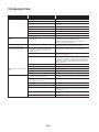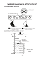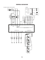
1
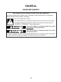
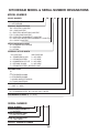
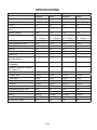
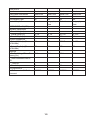
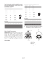
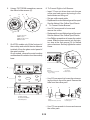
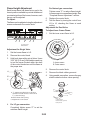
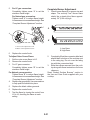
KAC-49
TECHNICAL EDUCATION
FLUSH-MOUNT
GAS COOKTOP
MODELS: KFGS306VSS, KFGU706VSS,
KFGS366VSS, KFGU766VSS
JOB AID 4317428
FORWARD
This KitchenAid Job Aid “Flush-Mount Gas Cooktop” (Part No. 4317428), provides the In-Home
Service Professional with information on the installation, operation, and service of the Flush-Mount
Gas Cooktop. For specific information on the model being serviced, refer to the “Use and Care
Guide,” or “Wiring Diagram” provided with the cooktop.
The Wiring Diagram used in this Job Aid is typical and should be used for training purposes only.
Always use the Wiring Diagram supplied with the product when servicing the cooktop.
GOALS AND OBJECTIVES
The goal of this Job Aid is to provide information that will enable the In-Home Service Professional
to properly diagnose malfunctions and repair the Flush-Mount Gas Cooktop.
The objectives of this Job Aid are to:
• Understand and follow proper safety precautions.
• Successfully troubleshoot and diagnose malfunctions.
• Successfully perform necessary repairs.
• Successfully return the cooktop to its proper operational status.
WHIRLPOOL CORPORATION assumes no responsibility for any repairs made on
our products by anyone other than authorized In-Home Service Professionals.
Copyright © 2008, Whirlpool Corporation, Benton Harbor, MI 49022
- ii -
TABLE OF CONTENTS
Page
GENERAL ............................................................................................................................... 1-1
Cooktop Safety................................................................................................................... 1-1
Model & Serial Number Designations................................................................................. 1-2
Model & Serial Number Label And Tech Sheet Locations................................................... 1-3
Specifications...................................................................................................................... 1-4
INSTALLATION INFORMATION ............................................................................................ 2-1
LP Gas And High Altitude Conversion Instructions............................................................2-11
PRODUCT OPERATION ....................................................................................................... 3-1
COMPONENT ACCESS ......................................................................................................... 4-1
Component Locations......................................................................................................... 4-1
Removing The Cooktop...................................................................................................... 4-2
Removing The Spark Switches, And The Standard Or Crown Burner Gas Valves............. 4-4
Removing The Power Supply Transformer And The Spark Module.................................... 4-7
Removing The Gas Shutoff Valve....................................................................................... 4-8
Removing A Spark Ignitor From Standard Or Crown Burner.............................................. 4-9
Removing Standard or Crown Burner................................................................................4-11
Removing The Power Supply Cord................................................................................... 4-13
COMPONENT TESTING ........................................................................................................ 5-1
Spark Switches................................................................................................................... 5-1
Crown Burner Switch.......................................................................................................... 5-2
Power Supply Transformer................................................................................................. 5-2
DIAGNOSTICS & TROUBLESHOOTING .............................................................................. 6-1
WIRING DIAGRAM & STRIP Circuit.................................................................................. 7-1
- iii -
— NOTES —
- iv -
GENERAL
COOKTOP SAFETY
Your safety and the safety of others are very important.
We have provided many important safety messages in this manual and on the appliance.
Always read and obey all safety messages.
This is the safety alert symbol.
This symbol alerts you to potential hazards that can kill or hurt you and others.
All safety messages will follow the safety alert symbol and either the word “DANGER” or “WARNING.” These words mean:
DANGER
You can be killed or seriously injured if you don’t
immediately follow instructions.
WARNING
You can be killed or seriously injured if you don’t
follow instructions.
All safety messages will tell you what the potential hazard is, tell you how to reduce the chance
of injury, and tell you what can happen if the instructions are not followed.
1-1
KITCHENAID MODEL & SERIAL NUMBER DESIGNATIONS
MODEL NUMBER
MODEL NUMBER K FG
PRODUCT GROUP
K = KITCHENAID
PRODUCT IDENTIFICATION
EC = ELECTRIC COOKTOP
GC = GAS COOKTOP
IC = ELECTRIC INDUCTION COOKTOP
FG = FLUSH GAS COOKTOP
ED = ELECTRIC DOWNDRAFT COOKTOP
ID = ELECTRIC INDUCTION DOWNDRAFT COOKTOP
GL = GAS LP COOKTOP
MERCHANDISING SCHEME
K = STANDARD KITCHENAID
S = SUPERBA
U = ULTIMA
MATERIAL / STYLE / WIDTH
1ST POSITION
2ND POSITION
0 = TEMPERED GLASS 0 = 30" WIDE
1 = STAINLESS STEEL 5 = 15" WIDE
4 = COMMERCIAL STYLE 6 = 36" WIDE
5 = CERAMIC GLASS 8 = 48" WIDE
7 = STAINLESS STEEL W/CLEAR COAT
FEATURE CODE
0=
1=
5 = STANDARD KNOBS
6 = STANDARD KNOBS
7 = KNOBS W/ELECTRONICS
8 = TOUCH CONTROLS
YEAR OF INTRODUCTION
T = 2007 V = 2008
COLOR CODE
SS = STAINLESS STEEL BL = BLACK WH = WHITE
ENGINEERING CHANGE (0, 1, 2, ETC.)
SERIAL NUMBER
SERIAL NUMBER
X
DIVISION RESPONSIBILITY
X = OXFORD
YEAR OF PRODUCTION
U = 2007 W = 2008
WEEK OF PRODUCTION
41 = 41ST WEEK
PRODUCT SEQUENCE NUMBER
W
41
01002
1-2
S 30
6
V
SS
0
MODEL & SERIAL NUMBER LABEL
AND TECH SHEET LOCATIONS
The Model/Serial Number label and Tech Sheet locations are shown below.
Tech Sheet Location
(On Inside Of Cooktop)
Model/Serial Number Location
(On Bottom Of Cooktop)
1-3
SPECIFICATIONS
Model Number
Canadian Model Number
Colors
Installs Over Undercounter
Oven
Agency Ratings
Electric Supply
Power Cable Location
Total Connected Load
COOKTOP
Surface
Clear Coat
BURNERS
Electronic Ignition with Electronic Re-ignition
L.P. Convertible (No Additional
Kit Needed)
Number of Burners & Burner
BTU (Nat./L.P..)
Left Front
Right Front
Left Rear
Right Rear
Center
Low Turn Down - LR Burner
Removable Burner Caps
BURNER GRATES
Grates
Grate Finish
Contiguous Grates
30”
Superba
KFGS306VSS
KFGS306VSS
SS
Yes
36”
Ultima
Superba
KFGU706VSS KFGS366VSS
KFGU706VSS KFGS366VSS
SS
SS
Yes
Yes
Ultima
KFGU766VSS
KFGU766VSS
SS
Yes
CSA
120 VAC, 60
HZ, 10 Amps
Center Rear
2VA
CSA
120 VAC, 60
HZ, 10 Amps
Center Rear
9,8VA
CSA
120 VAC, 60
HZ, 10 Amps
Center Rear
2VA
CSA
120 VAC, 60
HZ, 10 Amps
Center Rear
9,8VA
SS
No
SS
Yes
SS
No
SS
Yes
Yes
Yes
Yes
Yes
Yes
Yes
Yes
Yes
5
5
5
5
9,100
10,000
6,000
7,000
15,000
1200
Yes
9,100
12,000
6,000
7,000
15,000
1200
Yes
10,000
10,000
6,000
7,000
18,000
1200
Yes
12,000
10,000
6,000
7,000
20,000
1200
Yes
3-piece
Matte Bk
Yes
3-piece
Matte Bk
Yes
3-piece
Matte Bk
Yes
3-piece
Matte Bk
Yes
1-4
CONTROLS
Location
Removable Dials/Knobs
Lock Out
Hot Indicator Light
Control Graphics
DIMENSIONS - IN. (CM)
Exterior Dimensions
Overall Height (in)
Overall Width (in)
Overall Depth (in)
Cutout Dimensions
Cutout Width (in) (Measure
Or Min/Max)
Cutout Depth (in) (Measure
Or Min/Max)
Ratings
Electric Voltage/Phase/Frequency (Hz)
Total Connected Load In
kW
120V AC
Circuit Amps
ACCESSORIES
LP Conversion Kit Part/
Comment
Front
Metal Puck
No
No
Etched
Front
Metal Puck
Yes
Yes
Serigraphy on
glass
Front
Metal Puck
No
No
Etched
Front
Metal Puck
Yes
Yes
Serigraphy on
glass
30 1/4”
21”
30 1/4”
21”
36 7/32”
21”
36 7/32”
21”
29”
29”
35 1/4”
35 1/4”
20”
20”
20”
20”
60 Hz
60 Hz
60 Hz
60 Hz
15
15
15
15
8287082
8287082
8287082
8287082
1-5
— NOTES —
1-6
INSTALLATION INFORMATION
INSTALLATION REQUIREMENTS
TOOLS AND PARTS
Gather the required tools and parts before starting installation. Read and follow the instructions
provided with any tools listed here.
Tools needed
• Tape measure
• Flat-blade screwdriver
• 3/32" (#0 [2 mm]) flat blade screwdriver
(screwdriver shaft must be a minimum of
1 1/8" [28 mm] long) 1˝ (25 mm) drill bit (for
wall cabinet installations)
• 15/16" combination wrench
• Pipe wrench
• Wrench or pliers
• Needle-nose pliers
• Marker or pencil
• Pipe-joint compound resistant to LP gas
• Noncorrosive leak-detection solution
Parts needed
Check local codes and consult gas supplier.
Check existing gas supply and electrical supply. See “Electrical Requirements” and “Gas
Supply Requirements” sections.
Parts supplied
• Gas pressure regulator
• Burner grates
• Burner caps
• Clamping brackets (2)
• 2 1/2" (6.4 cm) clamping screws (2)
A
A. Model/serial rating plate
• To eliminate the risk of burns or fire by reaching over heated surface units, cabinet storage space located above the surface units
should be avoided. If cabinet storage is to be
provided, the risk can be reduced by installing a range hood that projects horizontally a
minimum of 5" (12.7 cm) beyond the bottom
of the cabinets
• The cooktop should be installed in a location away from strong draft areas, such as
windows, doors and strong heating vents or
fans.
• All openings in the wall or floor where cooktop
is to be installed must be sealed.
• Cabinet opening dimensions that are shown
must be used. Given dimensions are minimum
clearances.
• Grounded electrical supply is required. See
“Electrical Requirements” section. Proper gas
supply connection must be available. See
“Gas Supply Requirements” section.
• The cooktop is designed to hang from the
countertop by its side flanges.
• The gas and electric supply should be located
as shown in “Installation Clearances” section
so that they are accessible without requiring
removal of the cooktop.
LOCATION REQUIREMENTS
IMPORTANT: Observe all governing codes and
ordinances. Do not obstruct flow of combustion
and ventilation air.
• It is the installer’s responsibility to comply
with installation clearances specified on the
model/serial rating plate. The model/serial
rating plate is located on the underside of
the cooktop base.
2-1
Installation Clearances
• Provide cutout in right rear corner of cutout
enclosure as shown to provide clearance for
gas inlet, power supply cord, and to allow the
rating label to be visible.
IMPORTANT: To avoid damage, check with your
builder or cabinet supplier to make sure that the
materials used will not discolor, delaminate or
sustain other damage.
Product Dimensions
A
B
C
J
D
K
E
G
F
A
B
M
L
H
N
I
C
A. 30 �⁄�� " (76.7 cm) on 30" (76.2 cm) models,
36 �⁄� " (92.0 cm) on 36" (91.4 cm) models
B. 21" (53.3 cm)
C. 3 �⁄� " (8.3 cm)
A. 30 " (76.2 cm) on 30 " (76.2 cm) models; 36" (91.4 cm) on
36 " (91.4 cm) models
B. Combustible area above countertop (shown by dashed box above)
C. 30 " (76.2 cm) minimum clearance between top of cooktop platform
and bottom of unprotected wood or metal cabinet (24" [61.0 cm]
minimum clearance if bottom of wood or metal cabinet is protected by
not less than �⁄� " [0.6 cm] flame retardant millboard covered with not
less than No. 28 MSG sheet steel, 0.015" [0.04 cm] stainless steel, or
0.024 " [0.06 cm] aluminum or 0.020 " [0.05 cm] copper). If installing a
range hood see NOTES.*
D. 13 " (33.0 cm) recommended upper cabinet depth
E. 1 �⁄� " (2.8 cm)
F. 20 " (50.8 cm)
G. 18" (45.7 cm) minimum clearance from upper cabinet to countertop
within minimum horizontal clearances to cooktop
H. Grounded outlet - Locate within 24" (61.0 cm) of right rear corner of
cutout
I. 29" (73.7 cm) on 30" (76.2 cm) models; 35¼" (89.5 cm) on
36" (91.4 cm) models
J. 24" (61.0 cm) minimum countertop depth is required
K. 2 �⁄� " (7.3 cm) minimum distance to rear combustible surface
L. Gas line opening - Wall: anywhere 5" (12.7 cm) below underside of
countertop. Cabinet floor: anywhere within 6" (15.2 cm) of rear wall is
recommended
M. 8" (20.3 cm) minimum distance to nearest left side combustible
surface.**
N. 8" (20.3 cm) minimum distance to nearest right side combustible
surface.**
30" (76.2 cm) Cooktop Overall: M + N must equal 48" (122.0 cm)
minimum + 29" (73.7 cm) cutout for cooktop or 77" (195.6 cm)
36" (91.4 cm) Cooktop Overall: M + N must equal 48" (122.0 cm)
minimum + 35¼" (89.5 cm) cutout for cooktop or 83¼" (211.5 cm)
**M + N combined must be at least 48" (122.0 cm) minimum overall
Example 1: M = 8" (20.3 cm) left side + N = 40" (101.6 cm) right side
= 48" (122.0 cm)
Example 2: M = 24" (61.0 cm) left side + N = 24" (61.0 cm) right side
= 48" (122.0 cm)
2-2
NOTES:
After making the countertop cutout, some
installations may require notching down
the base cabinet side walls to clear the
cooktop base. To avoid this modification,
use a base cabinet with sidewalls wider
than the cutout.
If cabinet has a drawer, a 4" (10.2 cm) depth
clearance from the countertop to the top
of the drawer (or other obstruction) in base
cabinet is required. The drawer depth may
need to be shortened to avoid interfering
with the regulator.
* If installing a hood above the range, follow the
hood instructions for dimensional clearances above the cooktop surface.
• The Tech Sheet provided is located inside
the cooktop on the left wall of the cooktop
base
GAS SUPPLY REQUIREMENTS
Observe all governing codes and ordinances.
IMPORTANT: This installation must conform
with all local codes and ordinances. In the absence of local codes, installation must conform
with American National Standard, National Fuel
Gas Code ANSI Z223.1 - latest edition or CAN/
CGA B149 - latest edition.
IMPORTANT: Leak testing of the cooktop must
be conducted according to the manufacturer’s
instructions.
Type of Gas
Natural Gas:
This cooktop is design-certified by CSA International for use with Natural gas or, after proper
conversion, for use with LP gas.
• This cooktop is factory set for use with Natural
gas. If converting to LP gas, see the following
“LP Gas Conversion” section. The model/
serial rating plate located on the underside
of the cooktop base has information on the
types of gas that can be used. If the types
of gas listed do not include the type of gas
available, check with the local gas supplier.
LP Gas Conversion:
Conversion must be done by a qualified service
technician.
No attempt shall be made to convert the cooktop from the gas specified on the model/serial
rating plate for use with a different gas without
consulting the serving gas supplier. See the
Gas Conversion instructions provided in the
literature package.
ELECTRICAL REQUIREMENTS
IMPORTANT: The cooktop must be electrically
grounded in accordance with local codes and
ordinances, or in the absence of local codes,
with the National Electrical Code, ANSI/NFPA
70 or Canadian Electrical Code, CSA C22.1.
If codes permit and a separate ground wire is
used, it is recommended that a qualified electrical installer determine that the ground path
is adequate.
A copy of the above code standards can be
obtained from:
National Fire Protection Association
One Batterymarch Park
Quincy, MA 02269
CSA International
8501 East Pleasant Valley Road
Cleveland, OH 44131-5575
• A 120-volt, 60 Hz, AC only, 15-amp, fused
electrical circuit is required. A time-delay fuse
or circuit breaker is also recommended. It is
recommended that a separate circuit serving
only this cooktop be provided.
• Electronic ignition systems operate within
wide voltage limits, but proper grounding
and polarity are necessary. Check that the
outlet provides 120-volt power and is correctly grounded.
2-3
Gas Supply Line
• Provide a gas supply line of 3/4" (1.9 cm) rigid
pipe to the cooktop location. A smaller size
pipe on longer runs may result in insufficient
gas supply. Pipe-joint compounds that resist
the action of LP gas must be used. Do not
use TEFLON®† tape. With LP gas, piping
or tubing size should be 1/2" minimum. Usually, LP gas suppliers determine the size and
materials used in the system.
Flexible metal appliance connector:
• If local codes permit, use a 1/2" or 3/4" I.D.
flexible stainless steel tubing gas connector,
designed by CSA to connect the cooktop to
the rigid gas supply line.
• Must include a shutoff valve:
The supply line must be equipped with a
manual shutoff valve. This valve should be
located in the same room but external to the
cooktop. It should be in a location that allows
ease of opening and closing. Do not block
access to shutoff valve. The valve is for turning on or shutting off gas to the cooktop.
B
A
C
A. Gas supply line
B. Shutoff valve “open” position
C. To cooktop
Gas Pressure Regulator
The gas pressure regulator supplied with this
cooktop must be used. The inlet pressure to
the regulator should be as follows for proper
operation:
Natural Gas:
Minimum pressure: 5" (12.7 cm) WCP
Maximum pressure: 7" to 14" (17.8 cm to 35.5
cm) WCP
LP Gas:
Minimum pressure: 11" (27.9 cm) WCP
Maximum pressure: 14" (35.5 cm) WCP
Contact local gas supplier if you are not sure
about the inlet pressure.
Burner Input Requirements
Input ratings shown on the model/serial rating
plate are for elevations up to 2,000 ft (609.6
m).
For elevations above 2,000 ft (609.6 m), ratings
are reduced at a rate of 4% for each 1,000 ft
(304.8 m) above sea level (not applicable for
Canada).
For elevations above 6,560ft (1999.5 m) a high
altitude kit is needed to avoid any reduced
power output. See separate LP gas conversion
instructions sheet.
• A 1/2" male pipe thread is needed for connection to the female pipe threads of the inlet
to the cooktop pressure regulator.
• Do not kink or damage the flexible metal
tubing when moving the cooktop.
Rigid pipe connection:
The rigid pipe connection requires a combination
of pipe fittings to obtain an in-line connection
to the cooktop. The rigid pipe must be level
with the cooktop connection. All strains must
be removed from the supply and fuel lines so
cooktop will be level and in line.
2-4
INSTALLATION REQUIREMENTS
INSTALL COOKTOP
2. The clamping brackets can be installed
before or after the cooktop is placed into
the cutout. Complete the following steps
for the option you choose.
Installing Brackets Before Placing Cooktop in Cutout
1. Using 2 or more people, place the cooktop
upside down on a covered surface.
2. Remove the attachment screws for the
selected bracket locations from the bottom
of the cooktop base.
3. Select bracket mounting holes that will allow the bracket to extend far enough out
from the cooktop for the installation of
2 1/2" (6.4 cm) clamping screws. See “Attach Cooktop to Countertop” for illustration
of clamping screw installation.
WARNING
Excessive Weight Hazard
Use two or more people to move and
install cooktop.
Failure to do so can result in back or
other injury.
Style 1: Cooktop over undercounter builtin oven
IMPORTANT: Clamping brackets should not
be used.
1. Using 2 or more people, place cooktop
right side up into the cutout.
NOTE: Make sure that the front edge of
the cooktop is parallel to the front edge of
the countertop. If repositioning is needed,
lift entire cooktop up from cutout to avoid
scratching the countertop.
Style 2: Cooktop over cabinets
1. Determine whether your cabinet construction provides clearance for installing clamping brackets at cooktop base ends. This
is the recommended location. Clamping
brackets can be installed on the front and
back of cooktop base bottom, if necessary.
A
B
A. Edge of cooktop base bottom
B. Clamping bracket
A
4. Attach brackets to cooktop base bottom
with bracket attachment screws using the
bracket mounting holes selected in Step
2.
5. Rotate brackets so they do not extend
beyond edge of cooktop base.
6. Tighten screws just enough to hold brackets
in place when cooktop is put in cutout.
7. Using 2 or more people, turn the cooktop
right side up and place in cutout.
C
D
B
E
A. Attachment screw holes for optional front and back
location.
B. Clamping bracket (end locations recommended)
C. cooktop base bottom
D. Attachment screw
E. Attachment screw location (recommended)
2-5
NOTE: Make sure that the front edge of
the cooktop is parallel to the front edge of
the countertop. If repositioning is needed,
lift entire cooktop up from cutout to avoid
scratching the countertop.
8. Loosen the screws and rotate the brackets
so that they are perpendicular to the edge
of the cooktop base and extend beyond its
edge. Securely tighten screws.
Installing Brackets After Placing Cooktop
in Cutout
1. Using 2 or more people, place cooktop right
side up into the cutout.
NOTE: Make sure that the front edge of
the cooktop is parallel to the front edge of
the countertop. If repositioning is needed,
lift entire cooktop up from cutout to avoid
scratching the countertop.
2. Remove the attachment screws for the
selected bracket locations from the bottom
of the cooktop base.
3. Select bracket mounting holes that will allow the bracket to extend far enough out
from the cooktop for the installation of 2
1/2" (6.4 cm) clamping screws.
4. Attach brackets to cooktop base bottom
with bracket attachment screws using the
bracket mounting holes selected in Step
3. Securely tighten screws.
MAKE GAS CONNECTION
To Assemble Pressure Regulator:
1. Using 2 or more people, stand the cooktop
on its side or back.
2. Connect the flexible stainless steel connector to the pressure regulator using a
½" male pipe thread adapter and nipple. A
combination of pipe fittings must be used
to connect the cooktop to the existing gas
line. Shown following is a typical connection. Your connection may be different,
according to the supply line type, size and
location.
3. Install the pressure regulator with the arrow pointing up toward the bottom of the
cooktop base and in a position where you
can reach the regulator cap.
B
F
A
A
C
D
B
E
A. Access cap
B. Rear of cooktop
C. Gas pressure regulator
D. Up arrow. Regulator must be installed with
arrow pointing up to cooktop bottom.
D
C
A. Cooktop
B. Cooktop base
C. Attachment screw
D. Clamping bracket (extends far enough beyond cooktop
base to allow installation of clamping screws)
E. 2½" (6.4 cm) clamping screw (to be installed in “Attach
Cooktop to Countertop”)
F. Countertop
2-6
IMPORTANT: All connections must be
wrench-tightened. Do not make connections to the gas regulator too tight. Making
the connections too tight may crack the
regulator and cause a gas leak. Do not allow the regulator to turn on the pipe when
tightening fittings.
Complete Connection
1. Open the manual shutoff valve in the gas
supply line. The valve is open when the
handle is parallel to the gas pipe.
Use only pipe-joint compound made for use
with Natural and LP gas.
Do not use TEFLON® tape. You will need to
determine the fittings required depending on
your installation.
A
Typical flexible connection
1. Apply pipe-joint compound made for use
with LP gas to the smaller thread ends of
the flexible connector adapters (see G in
following illustration).
2. Attach 1 adapter and nipple to the gas
pressure regulator and the other adapter
and nipple to the gas shutoff valve. Tighten
both adapters and nipples.
3. Use a 15/16" combination wrench and
pliers to attach the flexible connector to
the adapters. Check that connector is not
kinked.
B
A. Closed valve
B. Open valve
2. Test all connections by brushing on an
approved noncorrosive leak-detection
solution. Bubbles will show a leak. Correct
any leak found.
3. Remove surface burner caps and grates
from parts package. Align notches in burner
caps with pins in burner base. Burner caps
should be level when properly positioned.
If burner caps are not properly positioned,
surface burners will not light. Place burner
grates over burners and caps.
B
A
D
C
F
H
A. �⁄� " nipple
B. �⁄� " adapter
C. Flexible connector
D. ½" nipple
G
E
B
E. Gas pressure regulator
F. ½" adapter
G. Use pipe-joint compound.
H. Manual gas shutoff valve
A
C
A. Igniter electrode
B. Burner cap
C. Burner base
2-7
COMPLETE INSTALLATION
WARNING
Electronic Ignition System
Initial lighting and gas flame adjustments Surface burners use electronic igniters in place of
standing pilots. When the cooktop control knob
is pushed in and turned to the “LITE” position,
the system creates a spark to light the burner.
This sparking continues, as long as the control
knob is pushed in and turned to “LITE.”
Check Operation of Surface Burners
1. Push in and turn the surface burners control
knobs to the “LITE” position.
The surface burner flame should light within
4 seconds. The first time a surface burner
is lit it may take longer than 10 seconds to
light because of air in the gas line.
2. Check the flame on HI for a blue color.
It should be clean and soft in character.
No yellow tip, blowing or lifting of flame
should occur. Occasional orange flashes
are normal and reflect different elements
in the air or gas.
3. Repeat at LO position.
4. After verifying the proper burner operation, authorized service company for assistance
If burners do not light properly:
• Turn surface burner control knob to the OFF
position.
• Check that the power supply cord is plugged
in and the circuit breaker has not tripped or
the fuse blown.
• Check that the gas shutoff valves are set to
the “open” position.
• Check that burner caps are properly positioned on burner bases.
Recheck operation of surface burners. If a
burner does not light at this point, turn control
knobs to Off and contact your dealer or authorized service company for assistance
Electrical Shock Hazard
Plug into a grounded 3 prong outlet.
Do not remove ground prong.
Do not use an adapter.
Do not use an extension cord.
Failure to follow these instructions can
result in death, fire, or electrical shock.
4. Plug into a grounded 3 prong outlet.
ATTACH COOKTOP TO
COUNTERTOP
NOTE: This section applies only if you are using
clamping brackets.
F
A
B
E
D
C
A. Glass cooktop
B. Cooktop base
C. Attachment screw
D. Clamping bracket (extends far
enough beyond cooktop base
to allow installation of
clamping screws)
E. 2½" (6.4 cm) clamping screw
F. Countertop
1. Place the 2 1/2" (6.4 cm) clamping screws
into the brackets.
2. Check that the cooktop is still level.
3. Use a flat-blade screwdriver to tighten the
screws against the countertop. Do not
overtighten.
2-8
Turn adjustment screw “C” to the right to reduce
flame height, turn adjustment screw to the left
to increase flame height.
Adjust Flame Height
The surface burner “low” flame should be a
steady blue flame approximately 1/4" (0.64
cm) high.
A
B
A
C
B
A. Low flame
B. High flame
A. �⁄�� " (#0 [2.0 mm]) flat blade screwdriver
(screwdriver shaft must be a minimum of
1 �⁄� " (28.0 mm) long)
B. Control knob stem opening
C. Adjustment screw location
If the “low” flame needs to be adjusted:
The flame can be adjusted using the adjustment
screws underneath the control knob.
A
A
B
A
4. Replace the control knob.
5. Test the flame by turning the control from
LO to HI, checking the flame at each setting
Adjustment for Dual Valve:
1. Set the inner crown flame to LO.
A
A. Single valve
B. Dual valve
A
Adjustment for Single Valve:
1. Set the burner flame to LO.
2. Remove the control knob.
3. Hold knob stem with a pair of pliers. Use
a 3/32" (#0 [2 mm]) flat blade screwdriver
to turn the screw located within the shaft
of the control knob stem until the flame is
the proper size.
B
A. Inner crown
B. Outer crown
2-9
2. Remove the control knob.
3. Remove the black rubber grommet.
4. Using needle-nose pliers, remove the gray
shield inside the burner valve opening.
A
Med
B
12. Replace the control knob.
13. Test the flame by turning the control from
LO to HI, checking the flame at each setting.
If you need Assistance or Service:
Please reference the “Assistance or Service”
section of the Use and Care Guide or contact
the dealer from whom you purchased your
cooktop.
C
A. Control knob
B. Black rubber grommet
C. Gray shield
5. Tighten screw “A” to reduce flame height.
Loosen screw to increase flame height.
A
B
A. Adjustment screw - inner crown
B. Adjustment screw - outer crown
6. 7. 8. 9. Replace the control knob.
Set the outer crown flame to LO.
Remove the control knob.
Tighten screw “B” to reduce flame height.
Loosen screw to increase flame height.
10. Replace the gray shield. Use a screwdriver
to help push the shield into place.
11. Replace the black rubber grommet.
2-10
LP GAS AND HIGH ALTITUDE CONVERSION
INSTRUCTIONS
TOOLS AND PARTS
WARNING
Gather the required tools and parts necessary
for correct LP gas conversion.
Tools needed
• Flat-blade screwdriver
• T20 TORX®† screwdriver
• 3/32"(#0[2mm]) flat blade screwdriver (screwdriver shaft must be a minimum of 1 1/8"
[28.0 mm] long)
• Phillips screwdriver
• Adjustable wrench
• 7 mm nut driver
• 10 mm wrench
• 15 mm wrench
• 17 mm wrench
Parts supplied
• LP orifice package (8287082)
• Conversion instructions (W10181980)
• Conversion label (8287070)
High Altitude Conversion
To convert the cooktop for elevations above
6,560ft (1999.5 m), order a High Altitude Conversion Kit.
• Part Number W10163349 - LP high altitude
• Part Number W10163727 - Natural gas high
altitude
To order, see the “Assistance or Service” section of the Use andCare Guide.
†®TORX is a registered trademark of Textron
Innovations Inc.
IMPORTANT: Gas conversions from Natural
gas to LP gas must be done by a qualified
installer. Before proceeding with conversion,
shut off the gas supply to the cooktop prior to
disconnecting the electrical power.
2-11
This conversion kit shall be installed
by a qualified service agency in accordance with the manufacturer's instructions and all applicable codes and
requirements of the authority having
jurisdiction. If the information in these
instructions is not followed exactly, a
fire, explosion or production of carbon
monoxide may result causing property
damage, personal injury or loss of life.
The qualified service agency is responsible for the proper installation of this
kit. The installation is not proper and
complete until the operation of the converted appliance is checked as specified in the manufacturer's instructions
supplied with this kit.
In the State of Massachusetts, the following
installation instructions apply:
• Installations and repairs must be performed by a qualified or licensed contractor,
plumber, or gas fitter qualified or licensed
by the State of Massachusetts.
• If using a ball valve, it shall be a T-handle
type.
• A flexible gas connector, when used, must
not exceed 3 feet.
To Convert Gas Pressure Regulator
B
A
C
Explosion Hazard
Use a new CSA International approved
gas supply line.
Install a shut-off valve.
Securely tighten all gas connections.
If connected to LP, have a qualified
person make sure gas pressure does
not exceed 14˝ (36 cm) water column.
Examples of a qualified person include:
licensed heating personnel,
authorized gas company personnel, and
authorized service personnel.
Failure to do so can result in death,
explosion, or fire.
D
A. Access cap
B. Rear of cooktop
C. Gas pressure regulator
D. Gas flow
Convert from Natural Gas to LP Gas
1. Turn manual shutoff valve to the closed
position.
2. Unplug cooktop or disconnect power.
3. Determine the type of regulator you
have:
Style 1: The cap has a slot and “NAT” printed
on it.
Remove access cap by using a flat-blade
screwdriver or coin, turning the access cap
counterclockwise.
The gas pressure regulator has 2 settings that
are stamped on either side of the cap. Turn the
cap and reinstall into regulator with the stamp
“LP” visible from the outside of the regulator.
B
A
C
A. To cooktop
B. Shutoff valve (closed position)
C. Gas supply line
2-12
Style 2: The cap does not have a slot and
requires a wrench to be removed.
Remove the access cap by using a wrench,
turning the access cap counterclockwise.
Remove spring retainer from the cap by pushing against the flat side of the spring retainer.
Look at the spring retainer to locate the “NAT”
or “LP” position. Turn over the spring retainer
so the “LP” is showing on the bottom. Snap the
spring retainer back into the cap. Reinstall the
cap onto the regulator.
Line pressure testing at ½ psi gauge (14"
WCP) or lower
The cooktop must be isolated from the gas
supply piping system by closing its individual
manual shutoff valve during any pressure testing
of the gas supply piping system at test pressures
equal to or less than ½ psi (3.5 kPa).
5. If installed, remove the burner grates.
Use the following charts to match the correct
gas orifice spud with the burner location and
model being converted.
LP Gas Orifice Spud Chart
Burner
Rating
A
B
E
D
A. Access cap
B. Gasket
C. Gas pressure regulator
Color
5,000 BTU
C
D. LP position
E. NAT position
White
(no color)
Stamp
(A)
066
Size
0.66 mm
6,000 BTU
Green
074
8,000 BTU
Yellow
083
0.83 mm
9,100 BTU
Black
089
0.89 mm
11,000 BTU
Orange
097
0.97 mm
12,000 BTU
Outer
Inner
White
099
6
0.99 mm
0.5*0.5 mm
14,000 BTU
Outer
Inner
Yellow
108
6
1.08 mm
0.5*0.5 mm
16,000 BTU
Outer
Inner
Orange
115
6
1.15 mm
0.5*0.5 mm
No color
No color
No color
0.74 mm
A
A. Size
stamp
Burner Models
4. Test the gas pressure regulator and gas
supply line.
The regulator must be checked at a minimum
1" (2.5 cm) water column above the set pressure. The inlet pressure to the regulator should
be as follows for operation and checking the
regulator setting:
LP Gas:
Minimum pressure 10" (25.4 cm) W.C.P.
Supply pressure 14" (35.5 cm) W.C.P.
Gas Supply Pressure Testing
Line pressure testing above ½ psi gauge
(14" WCP)
The cooktop and its individual shutoff valve
must be disconnected from the gas supply
piping system during any pressure testing of
that system at test pressures in excess of ½
psi (3.5 kPa).
2-13
Model
No.
Right
front
Right
rear
Center
(outer)
Center
(inner)
Left
front
Left rear
KFGS306
089
Black
074
Green
099
White
6
No color
083
Yellow
066
White
(no color)
KFGS366
089
Black
074
Green
108
Yellow
6
No color
089
Black
066
White
(no color)
KFGU706
097
Orange
074
Green
099
White
6
No color
083
Yellow
066
White
(no color)
KFGU766
089
Black
074
Green
115
Orange
6
No color
097
Orange
066
White
(no color)
High Altitude Conversions
IMPORTANT: You must convert LP gas with
LP gas high altitude or Natural gas with Natural gas high altitude. If you need to convert
LP gas to Natural gas high altitude or Natural
gas to LP gas high altitude you must convert
the pressure regulator, for this you must follow
steps 1, 2, and 3 of the respective conversion
that you need.
LP Gas Orifice Spud Chart for High Altitude
Conversion
Burner Rating
Stamp (A)
6. Remove all burner caps and burner bases.
If necessary, remove the burner ring.
D
B
C
062
0.62 mm
6,000 BTU
070
0.70 mm
8,000 BTU
079
0.79 mm
9,100 BTU
085
0.85 mm
11,000 BTU
092
0.92 mm
093
6
0.93 mm
0.5*0.5 mm
14,000 BTU
Outer
Inner
100
6
1.00 mm
0.5*0.5 mm
16,000 BTU
Outer
Inner
107
6
1.07 mm
0.5*0.5 mm
E
C
A. Burner cap
B. Igniter electrode
C. Burner base
D. Gas tube opening
E. Burner ring
7. Using a T20 TORX® screwdriver, remove
the orifice holder screws (C).
A
12,000 BTU
Outer
Inner
D
B
Size
5,000 BTU
A
A
C
A
A
B
A. Size stamp
C
Burner Models
Model
No.
Right
front
Right
rear
Center
(outer)
Center
(inner)
Left
front
Left
rear
KFGS306
085
070
093
6
079
062
KFGS366
085
070
100
6
085
062
KFGU706
092
070
093
6
079
062
KFGU766
085
070
107
6
092
062
D
C
A. Igniter electrode
B. Orifice holder
C. Orifice holder screws
D. Orifice spud
Burner locations
D
C
B
E
8. On KFGU models only, lift the front part of
the cooktop and unhook the wire harness
to detach it from the glass control panel of
the metal cooktop.
A
A. Left front
B. Left rear
C. Center
B
D. Right rear
E. Right front
2-14
On all models, remove the metal cooktop and
the sheet of insulation from the cooktop base.
A B
C D
A
E
B
A. Orifice
B. Venturi
C. Second Groove
(16.0 mm LP gas
setting)
D. First groove (12.0 mm
natural gas setting)
E. Venturi screw
C
• Use 15.0 mm wrench to loosen the nut securing the tube to the orifice pack. Remove the
tube from the orifice pack.
A. Metal cooktop
B. Sheet of insulation
C. Cooktop base
A
9. To Convert Right or Left Burners:
• Insert 7.0 mm nut driver down onto the gas
orifice spud and remove by turning it counterclockwise and lifting out.
• Set gas orifice spud aside.
• Replace with correct LP gas orifice spud. See
the LP Gas Orifice Spud Charts.
10. To Convert Center Burners:
• Use 10.0 mm wrench to loosen and remove
the orifice.
• Replace with correct LP gas orifice spud. See
the LP Gas Orifice Spud Charts.
• Use Phillips screwdriver to loosen the venturi
screw. Slide the brass venturi into the injector, stop at the second groove (C). Securely
tighten the venturi screw.
B
C
A. Tube
B. Attachment nut (15.0 mm)
D
C. Adapter nut (17.0 mm)
D. Orifice spud
• Use 17.0 mm wrench to loosen and remove
the orifice pack.
• Replace with correct LP gas orifice spud.
See the LP Gas Orifice Spud Charts.
• Replace adapter nut and secure with 17.0
mm wrench. Reattach tube and secure attachment nut with 15.0 mm wrench.
11. Place Natural gas orifice spuds in plastic
parts bag for future use and keep with
literature package.
12. Replace sheet of insulation.
13. On KFGU models only, reattach wire harness to the control panel on the cooktop
glass.
14. Replace the metal cooktop and tighten all
the screws to secure cooktop to base.
15. Replace burner bases and tighten all the
orifice holder screws. Replace burner caps.
If necessary, replace burner ring.
2-15
IMPORTANT: The igniter electrode is ceramic
and could break during conversion. Be sure
that the electrode comes through the hole
in the burner head smoothly while tightening
screws.
A
The gas pressure regulator has 2 settings
which are stamped on either side of the cap.
Turn the cap and reinstall into regulator with
the stamp “NAT” visible from the outside of the
regulator.
B
NAT
C
A. Burner cap
B. Electrode
C. Burner base
16. Open shutoff valve in the gas supply line.
The valve is open when the handle is parallel to the gas pipe.
17. Plug in cooktop or reconnect power.
18. Adjust single and dual valve according to
"Flame Height Adjustment" section.
REMEMBER: Once you have completed
converting all the cooktop burners, test the
cooktop for leaks by brushing on an approved
noncorrosive leak-detection solution. Bubbles
will show, indicating a leak. Correct any leaks
found.
Style 2: The cap does not have a slot and
requires a wrench to be removed.
Remove the access cap by using a wrench,
turning the access cap counterclockwise.
Remove spring retainer from the cap by pushing against the flat side of the spring retainer.
Look at the spring retainer to locate the “LP”
or “NAT” position. Turn over the spring retainer
so the “NAT” is showing on the bottom. Snap
the spring retainer back into the cap. Reinstall
the cap onto the regulator.
A
B
Convert from LP Gas to Natural Gas
1. Turn manual shutoff valve to the closed
position.
2. Unplug cooktop or disconnect power.
3. Determine the type of regulator you
have:
Style 1: The cap has a slot and “LP” printed
on it.
Remove access cap by using a flat-blade
screwdriver or coin, turning the access cap
counterclockwise.
E
D
A. Access cap
B. Gasket
C. Gas pressure regulator
C
D. NAT position
E. LP position
4. If they are installed, remove the burner
grates.
2-16
Use the following charts to match the correct
gas orifice spud with the burner location and
model being converted.
Natural Gas Orifice Spud Chart for High Altitude Conversion
Burner Rating
Natural Gas Orifice Spud Chart
Burner Rating
Stamp (A)
Size
Stamp (A)
Size
6,000 BTU
105
1.05 mm
7,000 BTU
118
1.18 mm
9,100 BTU
128
1.28 mm
6,000 BTU
110
1.10 mm
10,000 BTU
142
1.42 mm
7,000 BTU
118
1.18 mm
12,000 BTU
148
1.48 mm
9,100 BTU
134
1.34 mm
10,000 BTU
142
1.42 mm
15,000 BTU
Outer
Inner
153
10
1.53 mm
0.5*0.82 mm*
12,000 BTU
155
1.55 mm
18,000 BTU
Outer
Inner
173
10
1.73 mm
0.5*0.82 mm*
20,000 BTU
Outer
Inner
183
10
1.83 mm
0.5*0.82 mm*
15,000 BTU
Outer
Inner
168
10
18,000 BTU
Outer
Inner
1.68 mm
0.5*0.82 mm
184
10
20,000 BTU
Outer
Inner
A
1.84 mm
0.5*0.82 mm
193
10
Burner Models
Model
No.
Right
front
Right
rear
KFGS306
142
118
Center
(outer)
168
Center
(inner)
10
Left
front
134
Left
rear
110
KFGS366
142
118
184
10
142
110
KFGU706
155
118
168
10
134
110
KFGU766
142
118
193
10
155
110
A. Size stamp
Burner Models
A. Size stamp
1.93 mm
0.5*0.82 mm
A
Model
No.
Right
front
Right
rear
Center
(outer)
Center
(inner)
Left
front
Left
rear
KFGS306
142
118
153
10
128
105
KFGS366
142
118
173
10
142
105
KFGU706
148
118
153
10
128
105
KFGU766
142
118
183
10
148
105
5. Remove all burner caps and burner bases.
If necessary, remove the burner ring.
High Altitude Conversions
IMPORTANT: You must convert LP gas with
LP gas high altitude or Natural gas with Natural gas high altitude. If you need to convert
LP gas to Natural gas high altitude or Natural
gas to LP gas high altitude you must convert
the pressure regulator, for this you must follow
steps 1, 2, and 3 of the respective conversion
that you need.
A
A
D
B
D
B
C
E
C
A. Burner cap
B. Igniter electrode
C. Burner base
D. Gas tube opening
E. Burner ring
2-17
6. Using a T20 TORX® screwdriver, remove
the orifice holder screws (C).
C
A
A
B
C
D
C
B
A. Igniter electrode
B. Orifice spud
C. Orifice holder screws
D. Orifice holder
7. On KFGU models only, lift the front part of
the cooktop and unhook the wire harness
to detach it from the glass control panel of
the metal cooktop.
On all models, remove the metal cooktop
and the sheet of insulation from the cooktop
base.
8. To Convert Right or Left Burners:
• Insert 7.0 mm nut driver down onto the gas
orifice spud and remove by turning it counterclockwise and lifting out.
• Set gas orifice spud aside.
• Replace with correct Natural gas orifice spud.
See the Natural Gas Orifice Spud Charts.
9. To Convert Center Burners:
• Use 10.0 mm wrench to loosen and remove the orifice.
• Replace with correct Natural gas orifice spud.
See the Natural Gas Orifice Spud Charts.
• Use Phillips screwdriver to loosen the venturi
screw. Slide the brass venturi into the injector, stop at the first groove (D) for Natural
gas conversions. Securely tighten the venturi
screw.
A B
CD
E
A
A. Orifice
B. Venturi
C. Second Groove (16.0 mm
LP gas setting)
B
D. First groove (12.0 mm Natural
gas setting)
E. Venturi screw
• Use 15.0 mm wrench to loosen the nut securing the tube to the orifice pack. Remove the
tube from the orifice pack.
C
A
A. Metal cooktop
B. Sheet of insulation
C. Cooktop base
B
C
A. Tube
B. Attachment nut (15.0 mm)
D
C. Adapter nut (17.0 mm)
D. Orifice spud
• Use 17.0 mm wrench to loosen and remove
the orifice pack.
2-18
LO
M
HI LITE
A
The cooktop burners use electronic igniters
in place of standing pilots. When the cooktop
control knob is pushed, the system creates a
spark to light the burner. This sparking continues
until the control knob is turned to the desired
setting.
To Check Operation of the Cooktop
Burners:
1. Push in and turn knobs to the LITE position. The cooktop burner flame should light
within 4 seconds. The first time a burner
is lit, it may take longer than 4 seconds to
light because of air in the gas line. Do not
leave the knob in the LITE position after
burner lights.
ED
10. Place LP gas orifice spuds in plastic parts
bag for future use and keep with literature
package.
11. Replace sheet of insulation
12. On KFGU models only, reattach wire harness to the control panel on the cooktop
glass.
13. Replace the metal cooktop and tighten all
the screws to secure cooktop to base.
14. Replace burner bases and tighten all the
orifice screws. Replace burner caps. If
necessary, replace burner ring.
IMPORTANT: The igniter electrode is ceramic and could break during conversion.
Be sure that the electrode comes through
the hole in the burner head smoothly while
tightening screws.
Lighting the Electronic Igniters
OFF
• Replace with correct Natural gas orifice spud.
See Natural Gas Orifice Spud Charts.
• Replace adapter nut and secure with 17.0
mm wrench. Reattach tube and secure attachment nut with 15.0 mm wrench.
B
C
A. Burner cap
B. Electrode
C. Burner base
15. Open shutoff valve in the gas supply line.
The valve is open when the handle is parallel to the gas pipe.
16. Plug in cooktop or reconnect power.
17. Adjust single and dual valve according to
"Flame Height Adjustment" section.
REMEMBER: Once you have completed
converting all the cooktop burners, test
the cooktop for leaks by brushing on an
approved noncorrosive leak-detection
solution. Bubbles will show, indicating a
leak. Correct any leaks found.
2. If burners do not light properly, turn the
control knob to the OFF position. Make
sure the burner caps are in the proper
position.
3. Check that the power supply cord is plugged
in. Check that the circuit breaker has not
tripped or the household fuse has not
blown.
4. Check that the shutoff valve is in the open
position.
5. Check burner operation again.
If one or all of the burners do not light at this
point, see “Assistance or Service” section in
the Use and Care Guide.
2-19
Flame Height Adjustment
Each burner flame has been factory set to the
lowest position available to provide reliable and
constant reignition of the burner; however, each
burner can be adjusted.
To Adjust:
The flame can be adjusted using the adjustment
screws underneath the control knob.
For Natural gas conversion:
Tighten screw “C” to reduce flame height.
Loosen screw to increase flame height. See
“Complete Burner Adjustment” section.
5. Replace the control knob.
6. Test the flame by turning the control from
LO to HI, checking the flame at each
setting.
Adjustment for Dual Valve
To Adjust Inner Crown Flame:
1. Set the inner crown flame to LO.
A
A
A
B
A
A
B
A. Single valve
B. Dual valve
Adjustment for Single Valve
1. Set the burner flame to LO.
2. Remove the control knob.
3. Hold knob stem with a pair of pliers. Use a
3/32" (#0 [2.0 mm]) flat blade screwdriver
to turn the screw located within the shaft
of the control knob stem until the flame is
the proper size.
A. Inner crown
B. Outer crown
2. Remove the control knob.
3. Remove the black rubber grommet.
4. Using needle-nose pliers, remove the gray
shield inside the burner valve opening.
A
B
C
A
Med
B
A. �⁄�� " (#0 [2.0 mm]) flat blade screwdriver
(screwdriver shaft must be a minimum of
1 �⁄� " (28.0 mm) long)
B. Control knob stem opening
C. Adjustment screw location
C
A. Control knob
B. Black rubber grommet
C. Gray shield
4. For LP gas conversion:
Completely tighten screw “C” to set the
minimum flame height.
2-20
5. For LP gas conversion:
Completely tighten screw “A” to set the
minimum flame height.
For Natural gas conversion:
Tighten screw “A” to reduce flame height.
Loosen screw to increase flame height. See
“Complete Burner Adjustment” section.
Complete Burner Adjustment
1. Check burner flame(s) for proper size and
shape. The cooktop “low” burner flame
should be a steady blue flame approximately 1/4" (0.64 cm) high.
A
A
B
B
A. Inner crown adjustment screw
B. Outer crown adjustment screw
A. Low flame
B. High flame
6. Replace the control knob.
To Adjust Outer Crown Flame:
1. Set the outer crown flame to LO.
2. Remove the control knob.
3. For LP gas conversion:
Completely tighten screw “B” to set the
minimum flame height.
For Natural gas conversion:
Tighten screw “B” to reduce flame height.
Loosen screw to increase flame height. See
“Complete Burner Adjustment” section.
4. Replace the gray shield. Use a screwdriver
to help push the shield into place.
5. Replace the black rubber grommet.
6. Replace the control knob.
7. Test the flame by turning the control from
LO to HI, checking the flame at each
setting.
2. Completely fill out the conversion label and
attach label to bottom of the cooktop next
to the rating tag. Do not cover the rating
tag with the conversion label.
3. Save the orifices removed from the cooktop along with these instructions for future
reference.
Read “Sealed Surface Burners” section in
the Use and Care Guide supplied with your
cooktop.
2-21
— NOTES —
2-22
PRODUCT OPERATION
Control Panel (Glass)
A
B
C
A. Left rear burner control knob
B. Surface burner locator
C. Left front burner control knob
D
E
F
D. Hot surface indicator
E. Center burner control knob
F. Control lock keypad and indicator light
Cooktop
F
H
G
G. Right front burner control knob
H. Right rear burner control knob
G
E
D
H
C
I
B
A
J
K
A. 12,000 Btu/h burner on 36" (91.4 cm) models
9,100 Btu/h burner on 30" (76.2 cm) models
B. Surface burner cap
C. Left surface burner grate
D. 6,000 Btu/h burner
E. Model and serial number plate (under cooktop)
F. 20,000 Btu/h burner on 36" (91.4 cm) models
15,000 Btu/h burner on 30" (76.2 cm) models
G. Center grate
H. 7,000 Btu/h burner
I. Right surface burner grate
J. 10,000 Btu/h burner on 36" (91.4 cm)
models
12,000 Btu/h burner on 30" (76.2 cm)
models
K. Control panel
Re-Ignition Features
Cooktop Lock
During the cooking cycle, if one or more burners
power off due to external causes (such as water
spillage, wind, etc.), The ignition system will
turn on to re-ignite the flame. When the flame
comes back on, the system will stop sparking.
Sparking may also occasionally occur when
using the low setting on a burner.
If the flame does not recover within 4 seconds,
the cooktop will lock. The Cooktop Lock indicator
light will turn on and a long beep will sound.
To unlock the cooktop, turn all control knobs to
the Off position, the Cooktop Lock indicator light
will turn off. Before restarting, check that the
burners are clean. See “Sealed Surfaces Burners” section. You may then continue cooking.
The Cooktop Lock helps to avoid unintended
use of the surface burners. If a control knob
is turned to Lite when the Cooktop Lock is on,
you will hear clicking and you may see the
igniter sparking, but the burner will not light.
To activate:
Turn off all burners and touch the lock key for
3 seconds. When the Cooktop Lock activates.
The Cooktop Lock Indicator Light will turn on
and 1 long beep will sound.
To deactivate:
Touch the lock key for 3 seconds, the indicator
light will turn off and 1 long beep will sound.
3-1
Tones
To Light:
Tones are audible signals, indicating the
following:
One Long Beep
• Activation/deactivation of the Cooktop Lock
function
Three Short Beeps
• Invalid operation - attempting to lock or unlock
cooktop with 1 or more burners are on.
1. Push in and turn knob counterclockwise to
LITE. All surface burners will click. Only the
burner with the control knob turned to Lite
will produce a flame.
2. Turn knob to anywhere between HI and LO.
Use the following chart as a guide when setting heat levels.
SETTING
Hot Surface Indicator Light
The Hot Surface Indicator Light is located between the left front and center control knobs.
The Hot Surface Indicator Light will glow as
long as any surface cooking area is too hot to
touch, even after the surface cooking area(s)
is turn off. If the cooktop is on when a power
failure occurs, the Hot Surface Indicator Lights
will remain on after the power is restored to the
cooktop. They will remain on until the cooktop
has cooled completely.
After a power failure, when the power failure
is restored the Hot Surface Indicator Light can
stay on for up to 30 minutes
Times when this is most likely to occur:
• After the cooktop is first installed.
• After a power failure.
• After a power failure while the cooktop is still
cooling (30 to 40 minutes after cooking).
• Any time power is disconnected from the
cooktop.
RECOMMENDED USE
Lite
Light the burner.
Hi
Start food cooking.
Bring liquid to a boil.
Medium
Between Hi and Lo
Fry or sauté foods.
Maintain a slow boil.
Cook soups, sauces and gravies.
Stew or steam foods.
Simmer
Simmer
Lo
Keep food warm.
REMEMBER: When cooktop is in use, the entire cooktop
area may become hot.
Power Failure
Cooktop will not operate during a power
failure. (Models KFGU Only)
3-2
COMPONENT ACCESS
This section instructs you on how to service each component inside the KitchenAid Flush-Mount
Gas Cooktop. The components and their locations are shown below.
COMPONENT LOCATIONS
Power Supply Cord
Left Standard Burners
Spark Module
Crown Burner
Gas Valves & Spark
Switches (5)
Right Standard Burners
Power Supply Transformer
Electronic Control (Part Of Cooktop)
4-1
Gas Shutoff Valve
(KFGU Model Only)
REMOVING THE COOKTOP
WARNING
Spreader
Cap
Cap
Electrical Shock Hazard
Disconnect power before servicing.
Replace all parts and panels before
operating.
Failure to do so can result in death or
electrical shock.
Spreader
Bezel
NOTE: The electronic control is part of the
cooktop and cannot be serviced separately.
1. Turn manual gas line shutoff valve to the
closed position.
2. Unplug cooktop or disconnect power.
3. Remove the burner grates from the cooktop.
4. Pull the knobs off the gas valves.
5. Remove the burner caps and bezels from
the standard burner bases.
6. Remove the components from the Crown
burner.
Bezel
Burner Grates
Gas Valve Knobs
7.
Remove the three T-20 screws from the
crown burner base and the two screws
from each of the standard burner bases.
Crown Burner
Screws (3 )
Standard Burner
Screws (2 each)
4-2
8. Lift the front of the cooktop just high enough
to access the electronic control connector,
and pull the wire connector off the connector pins. (KFGU models only)
Lift Cooktop
8. Lift the cooktop off the burner box and
remove it.
Connector
9. Lift the cooktop off the burner box and
remove it.
4-3
REMOVING THE SPARK SWITCHES, AND THE
STANDARD OR CROWN BURNER GAS VALVES
b) Pull the spark switches off each of the
standard gas valves. Pull the switches
straight out from the valves to unclip
and remove them.
WARNING
Standard Burner
Electrical Shock Hazard
Disconnect power before servicing.
Replace all parts and panels before
operating.
Failure to do so can result in death or
electrical shock.
P
O ull
ut
Spark Switch
1. Unplug cooktop or disconnect power.
2. Remove the cooktop (see page 4-2 for the
procedure).
c) To remove the spark switch on the (center) Crown burner, use a small-blade
screwdriver, and pry the switch off the
valve. NOTE: When you reinstall the
spark switch on the Crown burner, press
down on the spark switch actuator so
that it fits under the valve actuator.
Gas Valves
NOTE: The spark switches are serviced as an
assembly and cannot be serviced separately.
3. To remove the spark switches:
a) Remove the rubber covers from each
of the gas valves.
Spark Switch
Actuator
y
Pr f f
O
Crown Burner
Valve
Actuator
Gas Valve Covers
Continued on the next page.
4-4
d) Remove the screw from the gas manifold clamp and remove the gas valve.
d) Unlatch and disconnect the main wire
connector from the spark switches and
remove the switches.
Spark Switch
Connector
4. To remove a standard gas valve:
a) Remove the spark switch from the valve
you are accessing (see step 3).
b) Remove the six screws from the front
burner box access panel and remove
the panel.
Gas Manifold
Clamp Screw
e) Check the rubber seal on the gas
valve stem and make sure that it is
not cracked, or torn. If so, replace the
seal.
Access Panel & 6 Screws
c) Disconnect the 1/2˝ gas outlet line fitting from the gas valve.
Gas Valve
Seal
Gas Line
Fitting
4-5
5. To remove the Crown burner gas valve:
a) Remove the spark switch from the Crown
burner gas valve (see step 3c).
b) Remove the six screws from the front
burner box access panel and remove
the panel.
f) Remove the screw from the gas manifold
clamp and remove the Crown burner
gas valve.
Access Panel & 6 Screws
c) Disconnect the two wire connectors
from the from the switch terminals on
the Crown burner gas valve.
d) Push the locking tab and lift the switch
off the Crown burner gas valve holder
pins.
Crown Burner Gas Valve
Pins
Gas Manifold
Clamp Screw
Switch
g) Check the rubber seal on the Crown
burner gas valve stem and make sure
that it is not cracked, or torn. If so, replace the seal.
GY Wire
WH Wire
Gas Valve
Seal
Locking Tab
e) Disconnect the two 1/2˝ gas line fittings
from the gas valve.
Gas Line Fittings
4-6
REMOVING THE POWER SUPPLY TRANSFORMER
AND THE SPARK MODULE
WARNING
5-Wire
Connector
2-Wire
Connector
Electrical Shock Hazard
Disconnect power before servicing.
Replace all parts and panels before
operating.
Failure to do so can result in death or
electrical shock.
Power Supply Transformer
4. To remove the spark module:
a) Remove the two screws from the shield
and remove the shield.
1. Unplug cooktop or disconnect power.
2. Remove the cooktop (see page 4-2 for the
procedure).
Spark Module Shield
Screws
Spark Module
Power Supply Transformer
3. To remove the power supply transformer:
a) Unlatch and disconnect the 2-wire and
5-wire connectors from the transformer
(see the top right photo).
b) Remove the two screws from the transformer and remove it.
b) Disconnect the burner ignitor wire connectors, and the 8-, 4-, and 10-wire
connectors from the spark module
terminals.
c) Remove the two screws from the spark
module and remove the module.
Ignitor Connectors
8-Wire Connector
4-Wire Connector
Not Used
RF
RR
C
LR
LF
Spark Module
Screw
Screw
10-Wire Connector
4-7
REMOVING THE GAS SHUTOFF VALVE
WARNING
5. Remove the burner assembly then 4 screws
securing manifold pipe.
Manifold Pipe Screws
Electrical Shock Hazard
Disconnect power before servicing.
Replace all parts and panels before
operating.
Failure to do so can result in death or
electrical shock.
1. Unplug cooktop or disconnect power.
2. Remove the cooktop (see page 4-2 for the
procedure).
Gas Shutoff Valve
Gas Shutoff Valve
3. Disconnect the two wire connectors from
the gas shutoff valve terminals (see the
top right photo).
4. Remove the manifold pipe. (The gas shutoff
valve is serviced with the manifold pipe)
(see page 4-11 removing standard burner
from cooktop for the procedure).
Locknut
Wire Connectors
4-8
REMOVING A SPARK IGNITOR FROM
STANDARD OR CROWN BURNER
b) Remove igniter retainer clip from standard burner.
WARNING
Electrical Shock Hazard
Disconnect power before servicing.
Replace all parts and panels before
operating.
Igniter
Igniter
Retainer
Clip
Failure to do so can result in death or
electrical shock.
1. Unplug cooktop or disconnect power.
2. Remove the cooktop (see page 4-2 for the
procedure).
Igniter
Retainer
Clip
Crown Burner
c) Remove igniter from standard burner.
Standard Burners
3. To remove spark ignitor from standard
burner.
a) Disconnect spark ignitor wire from spark
module.
Continued on the next page.
Spark Module
Igniter Wires
4-9
4. To remove spark igniter from crown
burner.
a) Disconnect spark ignitor wire from spark
module.
Spark Module
d) Lift crown burner up and rotate to expose two screws on back of mounting
plate.
e) Remove two screws from back of
mounting plate attached to crown
burner and remove mounting plate.
Igniter Wires
b) Disconnect two gas fittings from crown
burner.
Mounting Screws
Crown Burner
f) Remove c-clip from crown burner igniter
to release igniter from crown burner.
Gas Fittings
c) Remove two screws from crown burner
mounting plate.
C-Clip
g) Pull igniter and igniter wire out of top
of crown burner to remove.
Mounting Screws
4-10
REMOVING STANDARD OR CROWN BURNER
WARNING
Hold Down
Clamp Screw
Mounting Screws
Ground Screw
Electrical Shock Hazard
Disconnect power before servicing.
Replace all parts and panels before
operating.
Failure to do so can result in death or
electrical shock.
Mounting Screws
1. Unplug cooktop or disconnect power.
2. Remove the cooktop (see page 4-2 for the
procedure).
c) Remove 4 mounting screws located on
outside of burner box holding burner
supports to burner box.
d) Remove ground screw holding ground
wire to burner box.
e) Unlatch and disconnect the 2-wire
and 5-wire connectors from the
transformer.
5-Wire
Connector
2-Wire
Connector
Crown Burner
Standard Burners
3.
a)
b)
To remove standard burner from
cooktop.
Remove gas regulator from gas inlet line.
Remove 4 mounting screws holding burner
assembly to base and 1 hold down clamp
screw holding gas line.
4-11
Power Supply Transformer
Continued on the next page.
g) Disconnect gas line fitting from standard
burner.
h) Remove igniter from standard burner
(see removing a spark igniter from
standard or crown burner 4-9).
i) Turn burner assembly upside down on
protected surface.
j) Remove 2 screws from bottom of
standard burner attaching it to burner
support.
Mounting Screws
Mounting Screws
f) Lift burner assembly out of burner
box.
Gas Line Fitting
Burner Assembly
Mounting Screws
4. To remove crown burner from
cooktop.
a) Remove igniter from crown burner (see
removing a spark igniter from standard
or crown burner 4-9).
b) Remove crown burner from burner
assembly.
4-12
REMOVING THE POWER SUPPLY CORD
3. Remove the screw from the power supply
cord ground wire.
4. Press the locking tab on the power supply
cord connector and disconnect it from the
main connector.
WARNING
5. Remove the strain relief from the power
supply cord and pull the cord out of the
burner box mounting hole.
Electrical Shock Hazard
Disconnect power before servicing.
Replace all parts and panels before
operating.
Failure to do so can result in death or
electrical shock.
Strain Relief
1. Unplug cooktop or disconnect power.
2. Remove the cooktop (see page 4-2 for the
procedure).
Power Supply Cord
4-13
Ground Wire Screw
Power Supply Cord
Connector
— NOTES —
4-14
COMPONENT TESTING
Before testing any of the components, perform
the following checks:
• The most common cause for control failure
is corrosion on connectors. Therefore, disconnecting and reconnecting wires will be
necessary throughout test procedures.
• All tests/checks should be made with a
VOM or DVM having a sensitivity of 20,000
ohms-per-volt DC, or greater.
• Check all connections before replacing
components, looking for broken or loose
wires, failed terminals, or wires not pressed
into connectors far enough.
• Resistance checks must be made with
power cord unplugged from outlet, and
with wiring harness or connectors disconnected.
WARNING
Electrical Shock Hazard
Disconnect power before servicing.
Replace all parts and panels before operating.
Failure to do so can result in death or electrical shock.
SPARK SWITCHES
6-Pin Connector
Refer to page 4-3 for the procedure for accessing the spark switches.
1. Unplug cooktop or disconnect power.
2. Disconnect the spark switch 6-pin connector.
3. Set the ohmmeter to the R x 1 scale.
4. Rotate the valve to the setting shown in
the chart. Touch the ohmmeter test leads
to the indicated connector pins. The meter
should indicate an open or closed state.
5-1
Test
Points
Switch
Location
Pins P2-1
& P2-7
LF
Pins P2-2
& P2-7
LR
Pins P2-3
& P2-7
C
Pins P2-5
& P2-7
RF
Pins P2-4
& P2-7
RR
Valve
Setting
Meter
Reading
OFF
Open (∞)
LITE
Closed (0 Ω)
OFF
Open (∞)
LITE
Closed (0 Ω)
OFF
Open (∞)
LITE
Closed (0 Ω)
OFF
Open (∞)
LITE
Closed (0 Ω)
OFF
Open (∞)
LITE
Closed (0 Ω)
WARNING
Electrical Shock Hazard
Disconnect power before servicing.
Replace all parts and panels before operating.
Failure to do so can result in death or electrical shock.
CROWN BURNER SWITCH
POWER SUPPLY TRANSFORMER
Switch (N.O.)
Primary Connector
Refer to page 4-3 for the procedure for accessing the Crown burner switch.
1. Unplug cooktop or disconnect power.
2. Disconnect the wire connectors from the
switch terminals.
3. Set the Crown burner to the OFF position.
4. Set the ohmmeter to R x 1.
5. Touch the ohmmeter test leads to the switch
terminals. The meter should indicate an open
circuit (infinite).
6. Set the Crown burner to the LITE position.
The meter should indicate a closed circuit
0Ω
Refer to page 4-6 for the procedure for accessing the power supply transformer.
1. Unplug cooktop or disconnect power.
2. Disconnect the power supply transformer
primary (2-pin) connector.
3. Set the ohmmeter to the R x 1 scale.
4. Touch the ohmmeter test leads to the transformer connector pins. See transformer
table below.
TRANSFORMER TABLE
R ES IS TANCE
TES T
TYP
UNITS
CONDITIONS
Rp
Primary Coil
Resistance
60 ± 6
Ω
22 °C
Rs 1-2
Secondary Coil
Resistance
4.7 ± 0.5
Ω
22 °C
Rs 2-3
Secondary Coil
Resistance
4.7 ± 0.5
Ω
22 °C
Rs 4-5
Secondary Coil
Resistance
306 ± 30
Ω
22 °C
5-2
DIAGNOSTICS & TROUBLESHOOTING
WARNING
Electrical Shock Hazard
Disconnect power before servicing.
Replace all parts and panels before operating.
Failure to do so can result in death or electrical shock.
DIAGNOSTICS
IMPORTANT
Electrostatic Discharge (ESD)
Sensitive Electronics
ESD problems are present everywhere.
ESD may damage or weaken the electronic control assembly. The new control
assembly may appear to work well after
repair is finished, but failure may occur at
a later date due to ESD stress.
• Use an anti-static wrist strap. Connect
wrist strap to green ground connection
point or unpainted metal in the appliance.
Disconnect power and perform the following
checks:
• A potential cause of a control not functioning is corrosion on connections. Observe
connections and check for continuity with
an ohmmeter.
• All tests/checks should be made with a VOM
or DVM having a sensitivity of 20,000 ohms
per volt DC or greater.
• Check all connections before replacing components, looking for broken or loose wires,
failed terminals, or wires not pressed into
connectors far enough. Damaged harness
must be entirely replaced. Do not re-work a
harness.
-OR Touch your finger repeatedly to a green
ground connection point or unpainted
metal in the appliance.
• Resistance checks must be made with power
cord unplugged from outlet, and with wiring
harness or connectors disconnected.
• Before removing the part from its package, touch the anti-static bag to a green
ground connection point or unpainted
metal in the appliance.
• Avoid touching electronic parts or terminal contacts; handle electronic control
assembly by edges only.
• When repackaging failed electronic control assembly in anti-static bag, observe
above instructions.
6-1
TROUBLESHOOTING
P R OB LEM
P OS S I B LE CAUS E
ACTI ON
No spark when any control is turned. 1. No power to unit.
1. Check power is on.
2. Control connection not correctly plugged in
2. Check connector for contamination or loose connections.
3. Transformer not properly working.
3. Check transformer coil resistances according to transformer table,
page 6-3.
4. Bad ground connection.
4. Check all ground connections for continuity.
5. Burners not properly grounded.
5. Check ground continuity.
6. Spark leads damaged, sparking onto nearby metal.
6. Visually check in dimmed light for sparking to nearby metal.
7. Grease or dirt build-up around electrode.
7. Clean and dry electrode and cap.
8. Spark gap to burner cap not correctly set.
8. Check if cap is correctly seated on burner.
No spark when one control knob is
turned.
1. Bad connection to switch harness or faulty reignition 1. Check to ensure switch harness connection is OK.
control board.
2. Check if wires are correctly attached to switch.
3. Check switch is correctly assembled on gas valve shaft.
4. Replace switch harness if necessary.
Power to ignition unit is OK.
One electrode is not sparking.
1. Faulty spark lead/electrode or faulty ignition unit
Intermittent sparking after ignition
Sparking occurs and burner does not
light.
Continual sparking after ignition
1. Easy check: To determine if ignition unit or lead is faulty, swap
spark lead to another terminal and check for spark.
1. Generally the cause is a bad ground which can be
caused by a build-up of cooking oils, solids,
cleansers, etc.
1. Clean and dry all parts. Ensure burner is correctly seated.
2. Burner ports blocked.
2. Clean and dry burner and electrode. R emember: flame mus t be near
electrode to sense current.
3. Low micro amp reading.
3. The unit will not s park if the current s ens ed by the reignition control
board drops below a certain level. This generally occurs at simmer or
when the flame is unstable due to winds, etc. Check on high power if
sparking stops. Adjust gas valve regulation screws. Clean and dry
burner and elctrode.
4. Spark gap to burner cap not correctly set
4. Check if cap is correctly seated on burner. Check electrode integrity.
5. Faulty reignition control board.
5. Replace after checking all the above.
1. No gas to appliance.
1. Verify proper gas s upply.
2. Burner not correctly s eated.
2. Check and tes t.
3. Burner port wet or dirty.
3. Clean and dry. Als o clean electrode.
1. Electrode wire does not correspond to relevant
reignition control board output.
1. Check if the electrode wire is assembled according to electrode map
assembly instructions located close to reignition control board.
2. Burner ports blocked or wet and not allowing
electrode to sense the current.
2. Clean and dry ports and electrodes.
3. Spark gap to burner not correctly set.
3. Check if cap is correctly seated on burner.
4. Bad ground connection.
4. Check all ground connections for continuity.
5. Faulty electrode.
5. Verify electrode integrity.
NOTE: The unit may still spark even if the spark lead is faulty, but it will
not detect flame.
6. Transformer not properly working.
6. Check transformer coil resistances according to transformer table,
page 6-3.
7. Faulty reignition control board.
7. Replace and test (only after checking all of the above).
6-2
TRANSFORMER TABLE
R ES IS TANCE
TES T
TYP
UNITS
CONDITIONS
Rp
Primary Coil
Resistance
60 ± 6
Ω
22 °C
Rs 1-2
Secondary Coil
Resistance
4.7 ± 0.5
Ω
22 °C
Rs 2-3
Secondary Coil
Resistance
4.7 ± 0.5
Ω
22 °C
Rs 4-5
Secondary Coil
Resistance
306 ± 30
Ω
22 °C
ELECTRODE ASSEMBLY FOR CENTER BURNER
ELECTRODE GAP FOR CENTER BURNER
6.31
CAP
+0.70
-1.20 mm
(0.248"
+0.028
-0.047
)
OUTER
SPREADER
SEE DETAIL B
BEAUTY
RING
DETAIL B
CROSS
RING
1.70
INNER CROWN
SUPPORT
+0.028
-0.047
)
A
SPRING
A
FASTEN SPRING
ELECTRODE ASSEMBLY FOR
RF, RR, LF, LR BURNERS
(0.067"
SECTION A-A
ELECTRODE
BURNER
BODY
+0.70
-1.20 mm
ELECTRODE GAP FOR RF, RR, LF, LR BURNERS
2.50±0.5mm (0.098"±0.019)
CAP
ELECTRODE
INJECTOR
HOLDER
ELECTRODE
CLIP
6-3
— NOTES —
6-4
WIRING DIAGRAM & STRIP CIRCUIT
CONTROL POWER INDICATOR
CENTER POWER
ON INDICATOR
SEE OPERATION DIAGRAM 1 & 2
HOT
SURFACE
15°±10°
CONTROL LOCK
HOLD FOR 5 SEC
0°
0°
230°
165°±10°
SWITCH ELECTRIC CONTACTS CLOSED
OPERATION DIAGRAM 1
230°
SWITCH ELECTRIC CONTACTS CLOSED
OPERATION DIAGRAM 2
ELECTRONIC CONTROL STRIP CIRCUIT
P2-10
W
BK
SOLENOID VALVE
P2-9
BK
NEUTRAL
LINE
P2-8 GR
HOT SURFACE
INDICATOR SWITCH
PN 8286917
SEE OPERATION DIAGRAM 2
P2-7 W
P2-6 GY
W
W
P2-5 BR
RF BURNER SWITCH
P2-4 BU
RR BURNER SWITCH
P2-3
P2-2
GY
CENTER
BURNER SWITCH
Y
LR BURNER SWITCH
P2-1 OR
LF BURNER SWITCH
7-1
SWITCH HARNESS
PN8286687
SEE OPERATION
DIAGRAM 1
7-2
JI
CONTR OL LOCK
HOLD FOR 5 S EC
P4-4
P4-6
P4-7
P4-8
V
R
GR
OR P4-5
GY
P4-3
W
ELECTRODES OUTPUT
HOT
S UR FACE
W
P2-1
P2-2
OR
Y
GY
ELECTRODE
POWER
CONTROL CONNECTION
COMMUNICATION
S WITCH HAR NES S
PN 8286687
LF BUR NER S WITCH
LR BUR NER S WITCH
CENTER
BUR NER S WITCH
R R BUR NER S WITCH
BU
P2-4
P2-3
R F BUR NER S WITCH
BR
P2-5
W
HOT S UR FACE
INDICATOR S WITCH
PN 8287058
W
W
BK
BK
P4-2
P4-1
W
P2-7
GY
GR
P2-8
S OLENOID VALVE
NOR MALLY CLOS ED
PN 9758382
P2-6
BK
P2-9
5 OR
OR
BK
3R
4 BR
2 BU
BU
R
1R
R
P2-10
P1-4
P1-3
P1-2
P1-1
N
GND
GR
W
BK
S1
S2
S3
S4
S5
L
W
R R BUR NER ON INDICATOR
R F BUR NER ON INDICATOR
OR
Y
GY
BU
BR
TRANS FOR MER
PN 8286690
S EE TRANS FOR MER TABLE, PAGE 4.
ELECTRONIC CONTROL WIRING DIAGRAM
UI PN8286666
CONTR OL LOCK
CENTER BUR NER ON INDICATOR
HOT S UR FACE INDICATOR
EOL TES TER
LR BUR NER ON INDICATOR
CONNECTOR
LF BUR NER ON INDICATOR
US ER INTER FACE HAR NES S PN 8286987
LF BUR NER
LR BUR NER
CENTER BUR NER
R R BUR NER
R F BUR NER
ELECTR ODES
IGNITOR S
R EIGNITION CONTR OL BOAR D
PN 8286829
POWER COR D
PN 8286692
WIRING DIAGRAM
SYMBOLS
GROUND (CHASSIS)
TRANSFORMER
PLUG WITH FEMALE
CONNECTOR
RELAY CONTACTS
RECEPTACLE WITH
MALE CONNECTOR
SOLENOID VALVE
SWITCH
PRODUCT SPECIFICATIONS
AND
WARRANTY INFORMATION SOURCES
IN THE UNITED STATES:
FOR PRODUCT SPECIFICATIONS AND WARRANTY INFORMATION CALL:
FOR WHIRLPOOL PRODUCTS: 1-800-253-1301
FOR KITCHENAID PRODUCTS: 1-800-422-1230
FOR ROPER PRODUCTS: 1-800-447-6737
FOR TECHNICAL ASSISTANCE WHILE AT THE CUSTOMER’S HOME CALL:
THE TECHNICAL ASSISTANCE LINE: 1-800-832-7174
HAVE YOUR STORE NUMBER READY TO IDENTIFY YOU AS AN
AUTHORIZED IN-HOME SERVICE PROFESSIONAL
FOR LITERATURE ORDERS:
PHONE: 1-800-851-4605
FOR TECHNICAL INFORMATION AND SERVICE POINTERS:
www.servicematters.com
IN CANADA:
FOR PRODUCT SPECIFICATIONS AND WARRANTY INFORMATION CALL:
1-800-461-5681
FOR TECHNICAL ASSISTANCE WHILE AT THE CUSTOMER’S HOME CALL:
THE TECHNICAL ASSISTANCE LINE: 1-800-488-4791
HAVE YOUR STORE NUMBER READY TO IDENTIFY YOU AS AN
AUTHORIZED IN-HOME SERVICE PROFESSIONAL