1
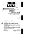
Operator's
Manual
MnN
2-Cycle
WEEDWACKER® GAS TRIMMER
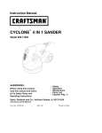
Model No. 316.791860
_BEL_EVABL_
STARTINO
EA S E _
*
*
*
*
*
*
SAFETY
ASSEMBLY
OPERATION
MAINTENANCE
PARTS LIST
ESPANOL, P. 13
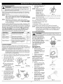
CAUTION:
Before using this
product, read this manual and
follow all safety rules and
operating
instructions.
Sears, Roebuck
and Co., Hoffman
Visit our website:
769-03835A
Estates, IL 60179, U.S.A.
www.sears.com/craftsman
3/08
CALIFORNIA
PROPOSITION
65 WARNING
THE ENGINE EXHAUST FROM THIS PRODUCT CONTAINS
CHEMICALS KNOWN TO THE STATE OF CALIFORNIA TO CAUSE
CANCER, BIRTH DEFECTS OR OTHER REPRODUCTIVE HARM.
TABLE OF CONTENTS
Safety Rules ..........................................
Warranty .............................................
Know Your Unit ........................................
Assembly Instructions ...................................
Oil and Fuel Information .................................
Starting/Stopping
Instructions ............................
Operating Instructions ...................................
Maintenance and Repair Instructions .......................
Cleaning and Storage ...................................
Troubleshooting Chart ...................................
Specifications
........................................
Parts List ...........................................
Service Numbers ..............................
SPARK ARRESTOR
2
4
4
4
5
5
6
7
8
9
10
E14
Back Cover
NOTE
NOTE: For users on U.S. Forest Land and in the states of California,
Maine, Oregon and Washington. All U.S. Forest Land and the state of
California (Public Resources Codes 4442 and 4443), Oregon and
Washington require, by law that certain internal combustion engines
operated on forest brush and/or grass-covered areas be equipped with a
spark arrestor, maintained in effective working order, or the engine be
constructed, equipped and maintained for the prevention of fire. Check
with your state or local authorities for regulations pertaining to these
requirements. Failure to follow these requirements could subject you to
liability or a fine. This unit is factory equipped with a spark arrestor. If
it requires replacement, ask your LOCAL SERVICE DEALER to installthe
Accessory Part #753-05169 Spark Arrestor Kit.
• IMPORTANT
READ ALL INSTRUCTIONS
SAFETY
BEFORE OPERATING
WARNING:
When using the unit, you must follow the
safety rules. Please read these instructions before operating
the unit in order to ensure the safety of the operator and any
bystanders. Please keep these instructions for later use.
• Read the instructions carefully. Be familiar with the controls and
proper use of the unit.
• Do not operate this unit when tired, ill or under the influence of
alcohol, drugs or medication.
• Children must not operate the unit. Teens must be accompanied
and guided by an adult.
• Inspect the unit before use. Replace damaged parts. Check for
fuel leaks. Make sure all fasteners are in place and secure.
Replace trimmer attachment parts that are cracked, chipped or
damaged in any way.
• Use only Hassle Free TM XTRA QUIET Spiral Line. Never use
metal-reinforced line, wire, chain or rope. These can break off
and become dangerous projectiles.
• Be aware of risk of injury to the head, hands and feet.
• Clear the area to be cut before each use. Remove rocks, broken
glass, nails, wire, string and other objects which may be thrown
or become entangled in the trimmer attachment. Clear the area of
children, bystanders and pets; keep them outside a 50-foot
(15 m) radius, at a minimum. Even then, they are still at risk from
thrown objects. Encourage bystanders to wear eye protection. If
you are approached, stop the unit immediately.
• Squeeze the throttle control and check that it returns
automatically to the idle position. Make all adjustments or repairs
before using the unit.
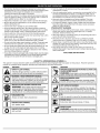
The purpose of safety symbols is to attract your attention to possible
dangers. The safety symbols, and their explanations, deserve your
careful attention and understanding. The safety warnings do not by
themselves eliminate any danger. The instructions or warnings they
give are not substitutes for proper accident prevention measures.
SYMBOL
MEANING
SAFETY
Indicates
warningpersonal
or caution.
Attention isALERT:
required in
order to danger,
avoid serious
injury. May be used in conjunction with other symbols or
pictographs.
NOTE:
Advises you of information or instructions vital to the
operation or maintenance of the equipment.
i, 1
serious injury to yourself or to others. Always follow the
safety precautions to reduce the risk of fire, electric shock
DANGER:
and
personal Failure
injury. to obey a safety warning will result in
injury to yourself Failureto
WARNING:
and others.
obey
Always
a safety
follow
warning
the safety
can result
precautions
in
to reduce the risk of fire, electric shock and personal injury.
CAUTION:
property damage
Failure
or personal
to obey injury
a safety
to yourself
warning or
may
to result
others.in
Always follow the safety precautions to reduce the risk of fire
electric shock and personal injury.
All information, illustrations, and specifications in this manual are based
on the latest product information available at the time of printing. We
reserve the right to make changes at any time without notice.
Read the Operator's Manual and follow all warnings and safety
instructions. Failure to do so can result in serious injury to the
operator and/or bystanders.
FOR QUESTIONS, CALL 1-800-659-5917
INSTRUCTIONS
•
FUEL SAFETY WARNINGS
WARNING:
I
Gasoline is highly flammable and its vapors
can exp ode f gn ted. Take the fo ow ng precaut ons:
I
m
• Store fuel only in containers specifically designed and approved
for the storage of such materials.
• Always stop the engine and allow it to cool before filling the fuel
tank. Never remove the fuel tank cap or add fuel when the engine is
hot. Never operate the unit without the fuel cap securely in place.
• Loosen the fuel tank cap slowly to relieve any pressure in the tank.
• Mix and add fuel in a clean, well-ventilated outdoor area where
there are no sparks or flames. Remove the fuel cap slowly, and
only after the engine stops. Do not smoke while fueling or mixing
fuel. Wipe up any spilled fuel from the unit immediately.
• Avoid creating a source of ignition for spilled fuel. Do not start the
engine until fuel vapors dissipate.
• Move the unit at least 30 feet (9.1 m) from the fueling source and site
before starting the engine. Do not smoke. Keep sparks and open
flames away from the area while adding fuel or operating the unit.
WHILE OPERATING
• Never start or run the unit inside a closed room or building.
Breathing exhaust fumes can be fatal. Operate this unit only in a
well-ventilated outdoor area.
• Wear safety glasses or goggles that meet ANSI Z87.1-1989 standards
and are marked as such. Wear ear/hearing protection when operating
this unit. Wear a face or dust mask if the operation is dusty.
• Wear heavy long pants, boots, gloves and a long sleeve shirt. Do
not wear loose clothing, jewelry, short pants, sandals or go
barefoot. Secure hair above shoulder level.
• Thetrimmer
attachment
shieldmustalways
beinplacewhile
operating
theunit.Donotoperate
unitwithoutbothtrimming
lines
extended,
andtheproperlineinstalled.
Donotextend
the
trimming
linebeyond
thelengthoftheshield.
• Thisunithasa clutch.Thetrimmer
attachment
remains
stationary
whentheengine
isidling.If itdoesnot,taketheunittoaSearsor
otherqualified
service
dealer
foranadjustment.
• AdjusttheD-handle
toyoursizeinordertoprovide
thebestgrip.
• Besurethetrimmer
attachment
isnotincontact
withanything
before
starting
theunit.
• Usetheunitonlyindaylight
orgoodartificial
light.
• Avoidaccidental
starting.
Beinthestarting
position
whenever
pullingthestarter
rope.Theoperator
andunitmustbeina stable
position
whilestarting.
RefertoStarting/Stopping
Instructions.
• Usetherighttool.Onlyusethistoolforitsintended
purpose.
• Always
holdtheunitwithbothhandswhenoperating.
Keepa firm
griponbothhandles
orgrips.
• Keephands,
face,andfeetawayfromallmoving
parts.Donot
touchortrytostopthetrimmer
attachment
whenitrotates.
• Donottouchtheengine,
gearhousing
ormuffler.
Thesepartsget
extremely
hotfromoperation,
evenaftertheunitisturnedoff.
• Donotoperate
theengine
faster
thanthespeedneeded
tocut,trim
oredge.Donotruntheengine
athighspeed
whennotcutting.
• Always
stoptheengine
whencuttingisdelayed
orwhenwalking
fromonecuttinglocation
toanother.
• Ifyoustrikeorbecome
entangled
withaforeign
object,
stoptheengine
immediately
andcheck
fordamage.
Donotoperate
before
repairing
damage.
Donotoperate
theunitwithloose
ordamaged
parts.
• Turntheengine
tooffanddisconnect
thesparkplugfor
maintenance
orrepair.
• Useonlyreplacement
partsoraccessories
recommended
forthis
toolthataredistributed
bySears
oraCraftsman
outlet.Useof
anyreplacement
partsoraccessories
purchased
elsewhere
may
behazardous,
andwillalsovoidyourwarranty.
• Keepunitcleanofvegetation
andothermaterials.
Theymay
become
lodged
between
thetrimmer
attachment
andshield.
• Toreduce
firehazard,
replace
afaultymuffler
andsparkarrestor.
Keeptheengine
andmuffler
freefromgrass,leaves,
excessive
grease
orcarbon
buildup.
OTHER SAFETY WARNINGS
• Never store the unit with fuel in the tank, inside a building where
fumes may reach an open flame (pilot lights, etc.) or sparks
(switches, electrical motors, etc.).
• Allow the engine to cool before storing or transporting. Be sure to
secure the unit while transporting.
• Store the unit in a dry place, secured or at a height to prevent
unauthorized use or damage. Keep out of the reach of children.
• Never douse or squirt the unit with water or any other liquid. Keep
handles dry, clean and free from debris. Clean after each use, see
Cleaning and Storage instructions (p. 8).
• Keep these instructions. Refer to them often and use them to
instruct other users. If you loan this unit to others, also loan them
these instructions.
SAVE THESE INSTRUCTIONS
• SAFETY & INTERNATIONAL
SYMBOLS
*
This operator's manual describes safety and international symbols and pictographs that may appear on this product.
manual for complete safety, assembly, operating and maintenance and repair information.
SYMBOL
MEANING
• SAFETY ALERT SYMBOL
,m
m
I ndicates danger, warning or caution. May be used in
I conjunct on w th other symbo s or p ctographs.
SYMBOL
MEANING
_1_O
_ _
"THROWN OBJECTS AND ROTATING CUTTER CAN I
CAUSE SEVERE INJURY
I
j_,_
WARNING: Small objects canbe propelled at high I
speed, causing injury. Keep away from the rotating rotor. I
' WARNING - READ OPERATOR'S MANUAL
Read the operator's manual(s) and follow all warnings
and safety instructions. Failure to do so can result in
serious injury to the operator and/or bystanders.
_i;_'_k
I
I Donot touch a hot muffler or cylinder, You may get
I burned. These parts get extremely hot from operationi
Thrown objects and loud noise can cause
severe eye injury and hearing loss.Wear eye protection
meeting ANSI Z87.1-1989 standards and ear protection when
operating this unit. Use a fullface shield when needed.
_"_
I Always use clean, fresh unleaded fuel
• ON/OFF STOP CONTROL
ON / START / RUN
I
I. HOTSURFACE
WARNING:
• UNLEADED FUEL
• KEEP BYSTANDERS AWAY
Keep al! bystanders, especially children
I WARNING:
I and pets, at least 50 feet (15 rn.) from the operating area.
lEAR EYE AND HEARING PROTECTION
r_
Read the operator's
I when
turned off they remain hot for a short time:
.OIL
A I Referto operator,s manUal f0rthe
_'/
" PRIMER BULB
_w_,jr__l/ I Push primer bulb fully and slowly
_mmr,,J/ I
._
proper type of oil.
10times.
I
..............
I
WARNING:
Sharp b!ade on trimmer attachment shield. I
• SHARP B_DE
I
prevent set ous nJury,d0 n°t t°uch the ne Cutt ng b ade. I
CRAFTSMAN FU LL WAR RANTY
If this Craftsman product fails due to a defect in material or workmanship within two years from the date of purchase, return it to any Sears
store, Parts and Repair Service Center, or other Craftsman outlet in the United States for free repair (or replacement if repair proves impossible).
This warranty applies for only 90 days if this product is ever used for commercial or rental purposes.
This warranty covers ONLY defects in materal and workmanship.
Sears will NOT pay for"
• Expendable items that can wear out from normal use within the warranty period, such as cutting line, filters or spark plugs.
• Repairs necessary because of accident or failure to operate or maintain the product according to all supplied instructions.
• Preventive maintenance, or repairs necessary due to improper fuel mixture, contaminated or stale fuel.
This warranty gives you specific legal rights, and you may also have other rights which vary from state to state.
Sears, Roebuck and Co., Hoffman Estates, IL 60179
Repair Protection Agreements
Congratulations on making a smart purchase. Your new Craftsman® product is designed and manufactured for years of dependable operation. But
like all products, it may require repair from time to time. That's when having a Repair Protection Agreement can save you money and aggravation.
Here's what the Repair Protection Agreement* includes:
[]
Expert service by our 10,000 professional repair specialists
[]
Unlimited service and no charge for parts and labor on all covered repairs
[]
Product replacement up to $1500 if your covered product can't be fixed
[]
Discount of 10% from regular price of service and related installed parts not covered by the agreement; also, 10% off regular price of
preventive maintenance check
[]
Fast help by phone - we call it Rapid Resolution - phone support from a Sears representative. Think of us as a "talking owner's manual."
Once you purchase the Repair Protection Agreement, a simple phone call is all that it takes for you to schedule service. You can call anytime
day or night, or schedule a service appointment online.
The Repair Protection Agreement is a risk-free purchase. If you cancel for any reason during the product warranty period, we will provide a
full refund. Or, a prorated refund any time after the product warranty period expires. Purchase your Repair Protection Agreement today!
Some limitations and exclusions apply. For prices and additional information
in the U.S.A. call 1-800-827-6655.
*Coverage in Canada varies on some items. For full details call Sears Canada at 1-800-361-6665.
Sears Installation Service
For Sears professional installation of home appliances, garage door openers, water heaters, and other major home items, in the U.S.A. or
Canada call 1-800-4-MY-HOME®.
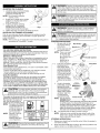
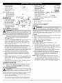
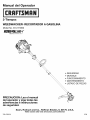
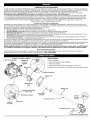
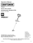
On/Off Stop Control
Fuel Cap
APPLICATIONS
As a trimmer:
•
Cutting grass and light weeds.
•
Edging
•
Decorative trimming around trees, fences, etc.
Other optional accessories may be used with this unit.
Starter
Rope Grip
Shaft Grip
Throttle
Control
D-Handle
Shoulder Strap
Loop
Shaft Housing
Air Filter/
Muffler Cover
Convertible
Primer Bulb
TM
Coupler
Line
Blade
Muffler
Spark Plug
Trimmer
Attachment
Trimmer
Shield-_
Hassle Free ® Cutting
d
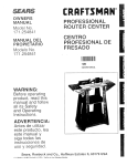
ADJUSTING THE D-HANDLE
1.
\
Locate the wing nut on the D-Handle.
Loosen the wing nut enough to
loosen the D-Handle (Fig. 1).
NOTE: Do not remove wing nut,
washer, or bolt.
2. Rotate the D-Handle to the upright
position on the front side of the
shaft housing (Fig. 1).
3. Hold the unit in the operating
position (Fig. 8). If necessary,
reposition the D-handle to the
Fig. 1
location that provides the best grip.
4. Tighten the wing nut until the D-Handle is secure.
INSTALLING THE TRIMMER ATTACHMENT
Prior to use, make sure trimmer attachment is installed correctly.
Please refer to Operating the Convertible TM Coupler System for
proper installation.
NOTE: Remove red cap or hanger from lower shaft housing prior to
assembling to Convertible TM coupler.
I
vapors may explode. Always stop the engine and allow it
to cool before filling the fuel tank. Do not smoke while
the tank. Gasoline
Keep sparks
and openflammable.
flames at a
distance
[ filling
WARNING:
is extremely
Ignited
from the area.
i,_
area. Wipe up any spilled fuel immediately. Avoid creating
source of ignition
for spilt
Dowell
notventilated
start the engine
i aWARNING:
Add fuel
in a fuel.
clean,
outdoor
until fuel vapors dissipate.
i_
WARNING:
outdoor area. Carbon
Operatemonoxide
this unit only
exhaust
in a well-ventilated
fumes can be
lethal in a confined area.
WARNING:
Avoid accidental
starting.
Make rope
sure (Fig.
you are
in the starting position
when pulling
the starter
5).
To avoid serious injury, the operator and unit must be
in a stable position while starting.
STARTING INSTRUCTIONS
1.
Mix gas with oil. See
Off and Fuel Mixing
Stop/Off (O)-_
/_- y/___
/
2.
OIL AND FUEL MIXING INSTRUCTIONS
Old and/or improperly mixed fuel are the main reasons for the unit not
running properly. Be sure to use fresh, clean unleaded fuel. Follow the
instructions carefully for the proper fuel/oil mixture.
Definition of Blended Fuels
Today's fuels are often a blend of gasoline and oxygenates such as
ethanol, methanol, or MTBE (ether). Alcohol-blended fuel absorbs
water. As little as 1% water in the fuel can make fuel and oil
separate. It forms acids when stored. When using alcohol-blended
fuel, use fresh fuel (less than 60 days old).
Using Blended Fuels
If you choose to use a blended fuel, or its use is unavoidable, follow
recommended precautions:
• Always use the fresh fuel mix explained in your operator's manual
• Always agitate the fuel mix before fueling the unit
• Drain the tank and run the engine dry before storing the unit
Using Fuel Additives
The bottle of 2-cycle oil that came with your unit contains a fuel additive
which will help inhibit corrosion and minimize the formation of gum
deposits. It is recommended that you use our 2-cycle oil with this unit. If
unavailable, use a good 2-cycle oil de-signed for air-cooled engines along
with a fuel additive, such as STA-BIL®Gas Stabilizer or an equivalent. Add
0.8 oz. (23 ml.) of fuel additive per gallon of fuel according to the insfructions
on the container. NEVER add fuel additives directly to the unit's fuel tank.
i,_
I
reliability, pay strict attention to the oil and fuel mixing
instructions on the 2-cycle oil container. Using improperly
For proper engine operation and maximum
mixed fuel can severely damage the engine.
JCAUTION:
Thoroughly mix the proper ratio of 2-cycle engine oil with unleaded
gasoline in a separate fuel can. Use a 40:1 fuel/oil ratio. Do not mix
them directly in the engine fuel
tank. See the table below for
specific gas and oil mixing ratios.
NOTE: One gallon (3.8 liters)
of unleaded gasoline
mixed with one 3.2
oz. (95 ml.) bottle of
2-cycle oil makes a
UNLEADED GAS
2 CYCLE OIL
40:1 fuel/oil ratio.
NOTE: Dispose of the old
1 GALLON US
3.2 FL. OZ.
fuel/oil mix in
(3.8 LITERS)
(95 ml)
accordance to
1
LITER
25 ml
Federal, State and
Local regulations.
MIXING RATIO - 40:1
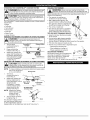
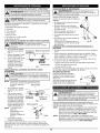
Fill the fuel tank with
the fuel/oil mixture.
NOTE: There is no need
Instructions.
to turn the unit
on. The On/Off
Stop Control is in /Y//i_ Throttle Control
the ON (I)
_J
position at all
Fig. 2
times (Fig. 2).
_3.
Fully pressand release
Primer Bulb
the primer bulb 10
times, slowly. Some
amount of fuel should
be visible inthe primer
bulb and fuel lines (Fig.
3). Ifyou can't see fuel
inthe bulb, press and
releasethe bulb as
many times as it takes
until you can see fuel in
Fig. 3
it.
_
Starting
4.
Crouch in the starting
/_qJ_;_'o"_%_
Position
position (Fig. 4). Do not II_I.P_L/_--P
squeeze the throttle,
and pull the starter rope X,.,_"_',_,"_/
with a controlled and
steady motion until the
unit starts. Wait 10 to
15 seconds, then
squeeze the throttle.
NOTE: The unit uses the
INCREDI.PULLTM
Fig. 4
starting system, which significantly reduces the effort required
to start the engine. You must pull the starter rope out far
enough to hear the engine attempt to start. There is no need
to pull the rope briskly-- there is no harsh resistance when
pulling. Be aware that this starting method is vastly different
from (and much easier than) what you may be used to.
IF... The engine does not start, go back to step 3.
NOTE: If the unit is hot and fails to start within 3 pulls of the
starter rope, squeeze the throttle control and pull the
starter rope until the unit starts.
STOPPING
INSTRUCTIONS
1.
Release your hand from the throttle control. Allow the engine to
cool down by idling.
2.
Press and hold On/Off Stop Control in the OFF (O) position until
engine comes to a complete stop (Fig. 2).
i lW,°..o
e ue
ove
ca sowI toavoidinu
fuel spray. Never operate the unit without the fuel cap
securely in place.
OPERATING THE CONVERTIBLE
TM
COUPLER SYSTEM
Before you begin using any attachment, read
and understand the manual that came with the attachment.
Follow all safety information contained within.
I
CAUTION:
[
WARNING:
These attachments are to be snapped into
the primary hole only. Using the wrong hole could lead to
personal injury or damage to the unit.
The Convertible
attachments.
•
•
•
•
•
•
HOLDING THE TRIMMER
TM
I
coupler system enables the use of these optional
Edger
Cultivator
Turbo Blower
Brushcutter
Pole Saw
Blade Pruner
Toavoidse
e sona'
ious
and [
damage to the unit, shut the unit off before removing or
installing attachment.
1.
Turn the knob
Convertible
Release Button
counterclockwise
to
loosen (Fig. 7).
2,
Press and hold the
release button (Fig. 5).
3. While firmly holding the
upper shaft housing, pull
the trimmer attachment or
Guide Recess
other attachment straight
out of the Convertible TM
Fig. 5
coupler (Fig. 6).
INSTALLING THE TRIMMER A'n'ACHMENT OR OTHER A'n'ACHMENT
TM
[A [
1.
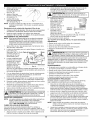
• Keep the trimmer attachment parallel
to the ground.
_,_ _,=
• Cut from left to right whenever possible.
Fig. 8
Trimmer to the right improves the unit's
trimmer efficiency. Clippings are thrown away from the operator.
• Trim only when grass and weeds are dry.
• The life of your trimmer line is dependent upon:
Following the trimming tips
What vegetation is being cut
Where vegetation is being cut
DECORATIVE TRIMMING
Decorative trimming is accomplished by
removing all vegetation around trees,
posts, fences and more. Rotate the
whole unit so that the trimmer
attachment is at a 30 ° angle to the ground (Fig. 9).
=e'o eo e atin0thisun't
esu ethatthe
[
release button is fully snapped into the primary hole (Fig. 6),
and that the knob (Fig. 7) is securely tightened.
NOTE:
Before operating the unit, stand in the operating position (Fig. 8).
Check for the following:
• The operator is wearing eye
protection and proper clothing
• With a slightly-bent right arm, the
operator's hand is holding the shaft grip
• The operator's left arm is slightly bent,
the left hand holding the D-handle
• The unit is at waist level
• The trimmer attachment is parallel to
the ground and easily contacts the
grass without the need to bend over
TIPS FOR BEST TRIMMING RESULTS
• Hedge Trimmer
REMOVING THE TRIMMER AI-rACHMENT OR OTHER AI-rACHMENT
[A [
protection to reduce the risk of injury when operating this unit.
To make installing or removing the attachment
the unit on the ground
or on a work bench.
Primary Hole
easier, place
Turn knob
counterclockwise
to
loosen (Fig. 7).
2. While firmly holding the
trimmer attachment or
other attachment, push it
straight into the
Housing
Housing
Convertible TM coupler
until the release button
Fig. 6
snaps firmly into the
90° Edging Hole
primary hole (Fig. 6).
NOTE: Aligning the release
button with the guide
recess will help
installation (Fig. 5).
3. Turn the knob clockwise
(Trimm__,,,
" Knob
to tighten (Fig. 7).
For decorative edging with the
line head trimmer attachment
Fig. 7
or other attachment, lock the
release button of the attachment into the 90 ° hole (Fig. 7).
Fig. 9
MAINTENANCE
,_1
SCHEDULE
6.
WARNING:
To prevent serious injury, never perform
I maintenance or repairs with unit running. Always service
I and repair a cool unit. Disconnect the spark plug wire to
I ensure that the un t cannot start.
Perform these required maintenance procedures at the frequency
stated in the table. These procedures should also be a part of any
seasonal tune-up.
NOTE: Some maintenance procedures may require special tools or
skills. If you are unsure about these procedures take your unit to
Sears or other qualified service dealer. Call 1-800-4-MY-HOME ®
for more information.
NOTE:
Maintenance, replacement, or repair of the emission
control devices and system may be performed by a Sears
or other qualified service dealer. Call 1-800-4-MY-HOME ¢
for more information.
In order to assure peak performance of your engine, inspection of the
engine exhaust port may be necessary after 50 hours of operation. If
you notice lost RPM, poor performance or general lack of acceleration,
this service may be required. If you feel your engine is in need of this
inspection, refer service to a Sears or other qualified service dealer.
Call 1-800-4-MY-HOME ®for more information. DO NOT attempt to
perform this process yourself as engine damage may result from
contaminants involved in the cleaning process for the port.
FREQUENCY
MAINTENANCE
REQUIRED
Before starting
engine
Fill fuel tank with fresh fuel
SEE
p. 5
Every 10 hours
Clean and re-oil air filter
p. 7
Every 25 hours
Check and clean spark arrestor
Check spark plug condition and gap
p. 8
p. 8
Every 50 hours
Inspect exhaust port and spark
arrestor screen for clogging or
obstruction
p. 8
LINE REPLACEMENT
Always use Craftsman Hassle-Free TM XTRA QUIET Spiral Line.
Choose the line size best suited for the job at hand. Red colored line
is designed for cutting grass and small weeds. Black colored line is
designed for cutting larger weeds and light brush.
NOTE: Before inserting new line into the holes in the cutting head,
identify the proper holes. Follow directions as shown on the
line glide plate. Do Not attempt to remove the cutting head
from the unit when replacing line.
1. Remove the old line and line glide plate from the cutting head.
2. Clean entire surface of cutting head. Note positions "A" and
"B" on the cutting head.
Arrow
3. Reinstall line glide plate
(Fig. 10). Align arrow with:
"A" when using medium
(red) or large (black) line,
or
"B" when using lines with
diameters smaller than
Cuttinc Head
medium (red)line
Glide Plate
NOTE: Line glide plate must
Fig. 10
be reinstalled in
cutting head before
inserting new line.
4. Insert both ends of your
_
POsiTtionlng
line through the proper
holes in the side of the
cutting head (Fig. 11).
5. Pull the line and make
sure the line is against the
hub and is fully extended
through the positioning
Fig. 11
tunnels (Fig. 12).
Correctly installed line will
be the same length on
both sides.
NOTE: Make sure that when
installing new line,
that the line is as
close to even as
possible. Any
variation in lengths
Fig. 12
may cause the unit to
vibrate excessively. If this happens, stop the unit and make
sure the line is even.
NOTE: Do not rest the Hassle-Free TM Cutting Head on the ground
while the unit is running.
Some line breakage will occur from:
• Entanglement with foreign matter
• Normal line fatigue
• Attempting to cut thick, stalky weeds
• Forcing the line into objects such as walls or fence posts
NOTE: During normal use the trimming line may become worn
unevenly which may cause excessive vibrations in the unit.
If this becomes uncomfortable or uncontrollable, stop the
unit and replace the line. Refer to the Line Replacement
instructions above.
AIR FILTER MAINTENANCE
iA i
To
avoid
serious
ersona'
in,ua'wa
turn
s
your unit off and allow it to cool before you clean or service it.
The condition of the air filter is
important to the operation of the
unit. A dirty air filter will restrict air
flow and change the air/fuel
mixture. This is often mistaken for Screws
an out of adjustment carburetor.
Check the condition of the air filter
before adjusting the idle speed
screw. Referto Air Filter
Maintenance.
Removing the Air
Filter/Muffler
Cover
Remove the four (4)screws
securing the air filter/
muffler cover (Fig. 13). Use
a flat blade or T20 Torx bit
screwdriver.
2.
Pull the cover from the
Air Filter _r
engine. Do not force.
Cleaning the Air Filter
Failure to maintain your air
filter properly can result in
poor performance or can
cause permanent damage to
your engine.
1. Remove air filter/muffler
cover. Refer to Removing
the Air Filter/Muffler
Cover above.
2. Turn cover over and look
inside to locate the air filter.
Remove the air filter from
inside the air filter/muffler
cover (Fig. 14).
,Screws
Fig. 13
1,
3.
4.
Wash the filter in detergent
and water (Fig. 15). Rinse
the filter thoroughly.
Squeeze out excess water.
Allow it to dry completely.
Apply enough clean SAE
30 oil to lightly coat the
filter (Fig. 16).
Fig. 14
J
Fig. 15
Fig. 16
5. Squeeze
thefilterto
spread
andremove
excess
oil(Fig.17).
6. Replace
theairfilter
insidetheairfilter/muffler
cover(Fig.14).
NOTE:Operating
theunit
without
theairfilter
andairfilter/muffler
coverassembly
will
VOIDthewarranty.
Reinstalling the Air
Filter/Muffler Cover
1. Place the air filter/muffler
Spark Arrestor Hood
2,
3.
4.
5.
4.
Install a correctly-gapped
spark plug in the cylinder
0.025 in.
head. Tighten by turning the (0.635 ram)
5/8-inch socket clockwise
until snug. If using a torque
wrench, torque to:
,/
110-120 in..Ib.
Engine
(12.3-13.5 N.m).
t
Fig. 20
Do not over-tighten.
5.
Reattach the plug boot.
TRANSPORTING
Slo_,
Muffler
• Allow the engine to cool before transporting.
• Drain fuel from unit.
• Tighten fuel cap before transporting.
• Secure the unit while transporting.
CLEANING
_,
WARNING:
To avoid serious personal injury, always turn your I
tr mmer off and a ow t to coo before you c ean or manta n t.
I
m
'*thes ar Iarrestorhoodan
screen are not tightened securely, they could fall off causing
damage to the unit and possible serious personal injury.
NOTE:
1.
Replace a cracked, fouled
or dirty spark plug. Set
the air gap at 0.025 in.
(0.635 ram) using a feeler
gauge (Fig. 20).
Fig. 17
carburetor and muffler.
Align the screw holes.
c°ver°vertheback°fthe
cr_ew_sp_ark
_
2. Insert
the four (4) screws
into the holes in the air
S
filter/muffler cover (Fig.
Tabs
Screen
13) and tighten. Do not
Fig. 18
over tighten.
SPARK ARRESTOR MAINTENANCE
i
3.
Pay close attention when disassembling the muffler so you
can put it back together correctly. Failure to do so will
damage the unit and may cause serious personal injury.
Remove air filter/muffler cover. Refer to Removing the Air
Filter/Muffler Cover.
Locate the muffler, but do not remove it. Find the screw on the
bottom of the muffler (Fig. 18). This screw holds the Spark
Arrestor Hood Assembly and the spark arrestor screen to the
bottom of the muffler. Remove this screw using either a Torx
T20 or flat blade screwdriver.
Using a small flat blade screwdriver, carefully pry up the spark
arrestor screen from the recessed hole, taking care to notice that
the "raised" part of the spark arrestor screen is inside the
recessed hole. Remove the spark arrestor screen from the muffler.
Clean the spark arrestor screen with a wire brush. Replace it if it
is damaged, or if you are unable to clean it thoroughly.
Reinstall the spark arrestor screen by putting the "raised"
portion of the screen inside the recessed hole of the muffler.
Make sure that the spark arrestor screen fits flat against the
muffler.
6.
Place the spark arrestor hood on top of the spark arrestor plate
with the "raised" side up and the opening facing AWAY from the
engine (Fig. 18). Verify that the exhaust will be directed AWAY
from the engine.
7. Replace the screw you removed in Step 2 and tighten securely.
8. Reinstall the air filter/muffler cover (Fig. 13).
CARBURETOR ADJUSTMENT
Use a small brush to clean off the outside of the unit. Do not use strong
detergents. Household cleaners that contain aromatic oils such as pine
and lemon, and solvents such as kerosene, can damage plastic housing
or handle. Wipe off any moisture with a soft cloth.
STO RAG E
• Never store a fueled unit where fumes may reach an open flame or spark.
• Allow the engine to cool before storing.
• Store the unit locked up to prevent unauthorized use or damage.
• Store the unit in a dry, well-ventilated area.
• Store the unit out of the reach of children.
LONG TERM STORAGE
If you plan on storing the unit for an extended time, use the
following storage procedure:
1. Carefully drain the fuel tank by running the unit dry or remove
fuel cap and tip the motor housing over and drain oil/gas fuel
into a container with the same 2-cycle fuel mixture. Do not use
fuel that has been stored for more than 60 days.
2.
Start the engine and allow it to run until it stalls. This ensures
that all fuel has been drained from the carburetor.
3.
Allow the engine to cool. Remove the spark plug and put 1 oz.
(30 ml) of any high quality motor oil or 2-cycle oil into the
cylinder. Pull the starter rope slowly to distribute the oil.
Reinstall the spark plug.
NOTE: Remove the spark plug and drain all of the oil from the
cylinder before attempting to start the trimmer after storage.
4. Thoroughly clean the unit and inspect it for any loose or
damaged parts. Repair or replace damaged parts and tighten
loose screws, nuts or bolts. The unit is ready for storage.
NOTE:
Careless adjustments can seriously damage your unit. Contact
a Sears or other qualified service dealer to make carburetor
adjustments. Call 1-800-4-MY-HOMEefor
more information.
REPLACING THE SPARK PLUG
iw.o...o=
oonotsand
scra eorc.eans
.ast,
I
ar .u0
electrodes. Grit in the engine could damage the cylinder.
Use a Champion RDJ7Y spark plug or equivalent. Remove the plug
after every 25 hours of operation and check its condition.
1. Stop the engine and allow it to cool. Grasp the plug boot firmly
and pull it from the spark plug.
2. Clean around the spark plug. Remove the spark plug from the
cylinder head by turning a 5/8-inch socket counterclockwise.
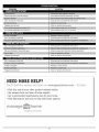
PROBLEM
SOLUTION
Primer bulb wasn't pressed enough
Press primer bulb fully and slowly 10 times
Old or improperly mixed fuel
Drain gas tank and add fresh fuel mixture
Plugged spark arrestor
Clean or replace spark arrestor
The outside temperature
is above 90 ° F
Pull the starter rope up to 10-15 times
I::IZ[_IZI::Iiv;JlillaHZ[e]idII.)ml=l
Old or improperly mixed fuel
Drain gas tank and add fresh fuel mixture
I=IZ[_IZI=ILv,
vJIiliHZ[e]iilF:T_ =1il=1t,T;'a
d=
Old or improperly mixed fuel
Drain gas tank and add fresh fuel mixture
Trimmer attachment
Stop the engine and clean the trimmer attachment
bound with grass
Plugged spark arrestor
Clean or replace spark arrestor
:!_[elI_I::gO':To,]
[T.I ".Zo_V_Vl
::1-'[o] -'![..1IP':11
I_lV_Vl:I::1
_ [o]ll II / I_[€
Old or improperly mixed fuel
Drain gas tank and add fresh fuel mixture
Air filter is plugged
Replace or clean air filter
Plugged spark arrestor
Clean or replace spark arrestor
NEED MORE HELP:'
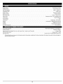
Engine Type ....................................................................................
Displacement .....................................................................................
Idle Speed RPM ..................................................................................
Operating RPM ........................................................................................
Ignition Type ......................................................................................
Ignition Switch ......................................................................................
Spark Plug Gap .................................................................................
Spark Plug .........................................................................
Lubrication .........................................................................................
Fuel/Oil Ratio ................................................................................................
Air-Cooled, 2-Cycle
32 cc (1.95 cu in.)
2,600 - 3,600 rpm
6,800+ rpm
Electronic Ignition
Rocker Switch
0.025 in. (0.635 mm)
Champion RDJ7Y or equivalent plug
Fuel/Oil Mixture
40:1
Carburetor ...................................................................................
Starter .............................................................................
Muffler ..........................................................................................
Incredi-Pull
Throttle .......................................................................................
Fuel Tank Capacity ...................................................................................
Diaphragm, All-Position
Starting Auto Rewind
Baffled with Guard
TM
Manual Spring Return
13 oz. (384 ml)
IB];tkv__1_']: r:l a iIt_?l/d:t hVAhV_l
_ ;1[:11 q:[+]: hVAI
_ Z/ _-_
Drive Shaft Housing ................................................................
Throttle Control ...................................................................................
Approximate Unit Weight (No fuel, with Hassle Free+_,shield, and D-handle) ........................................
Trimmer Mechanism ..............................................................................
Trimming Line ....................................................................
*
Steel Tube (Craftsman Convertible TM)
Finger-Tip Trigger
14 Ibs. (6 kg)
Hassle Free TM Head
Hassle Free TM XTRA QUIET Spiral Line
All specifications are based on the latest product information available at the time of printing. We reserve the right to make changes at
any time without notice.
10
CALIFORNIA / EPA EMISSION CONTROL WARRANTY STATEMENT
Your Warranty Rights and Obligations
The California Air Resources Board, the Environmental Protection Agency, and Sears, Roebuck and Co. (Sears) are pleased to explain the emission
control system warranty on your 2007 and later small off-road engine. In California and the 49 states, new small off-road engines must be designed,
built and equipped to meet the state's stringent anti-smog standards. Sears must warrant the emission control system on your small off-road engine
for the periods of time listed below provided there has been no abuse, neglect or improper maintenance of your small off-road engine.
Your emission control system may include parts such as the carburetor or fuel-injection system, the ignition system, and catalytic converter. Also
included may be hoses, belts, connectors and other emission-related assemblies.
Where a warrantable condition exists, Sears will repair your small off-road engine at no cost to you including diagnosis, parts and labor.
The 2007 and later small off-road engines are warranted for two years. If any emission-related part on your engine is defective, the part will be repaired
or replaced by Sears.
Owners Warranty Responsibilities
As the small off-road engine owner, you are responsible for the performance of the required maintenance listed in your operator's manual. Sears
recommends that you retain all receipts covering maintenance on your small off-road engine, but Sears cannot deny warranty solely for the lack
of receipts or for your failure to ensure the performance of all scheduled maintenance.
•
As the small off-road engine owner, you should however be aware that Sears may deny you warranty coverage if your small off-road engine
or a part has failed due to abuse, neglect, improper maintenance or unapproved modifications.
•
You are responsible for presenting your small off-road engine to a Sears Authorized Service Center as soon as a problem exists. The
warranty repairs should be completed in a reasonable amount of time, not to exceed 30 days.
If you have any questions regarding your warranty rights and responsibilities, you should call 1-800-4-MY-HOME ®.
Manufacturer's
Warranty Coverage
•
The warranty period begins on the date the engine or equipment is delivered to the retail purchaser.
•
The manufacturer warrants to the initial owner and each subsequent purchaser, that the engine is free from defects in material and
workmanship which cause the failure of a warranted part for a period of two years.
•
Repair or replacement of warranted part will be performed at no charge to the owner at an Authorized Sears Service Center. For the nearest
location please contact Sears at: 1-800-4-MY-HOME ®.
•
Any warranted part which is not scheduled for replacement, as required maintenance or which is scheduled for only for regular inspection
to the effect of "Repair or Replace as Necessary" is warranted for the warranty period. Any warranted part which is scheduled for
replacement as required maintenance will be warranted for the period of time up to the first scheduled replacement point for that part.
•
The owner will not be charged for diagnostic labor which leads to the determination that a warranted part is defective, if the diagnostic work
is performed at an Authorized Sears Service Center.
•
The manufacturer is liable for damages to other engine components caused by the failure of a warranted part still under warranty.
•
Failures caused by abuse, neglect or improper maintenance are not covered under warranty.
•
The use of add-on or modified parts can be grounds for disallowing a warranty claim. The manufacturer is not liable to cover failures of
warranted parts caused by the use of add-on or modified parts.
•
In order to file a claim, go to your nearest Authorized Sears Service Center. Warranty services or repairs will be provided at all Authorized
Sears Service Centers.
•
Any manufacturer approved replacement part may be used in the performance of any warranty maintenance or repair of emission related
parts and will be provided without charge to the owner. Any replacement part that is equivalent in performance or durability may be used
in non-warranty maintenance or repair and will not reduce the warranty obligations of the manufacturer.
Emission Warranty Parts List:
The following components are included in the emission-related warranty of the engine: air filter, carburetor, primer, fuel lines, fuel pick up/fuel
filter, ignition module, spark plug, and muffler. Valves and Cam are additionally included if your engine is a 4-Stroke Model.
11
CALIFORNIA
EVAPORATIVE EMISSION CONTROL WARRANTY
STATEMENT
Your Warranty Rights and Obligations
The California Air Resources Board and Sears, Roebuck and Co. (Sears) is pleased to explain the evaporative emission control system's warranty
on your 2007 model year and later small off-road (equipment type) engine. In California, new equipment that use small off-engines must be designed,
built, and equipped to meet the State's stringent anti-smog standards Sears must warrant the evaporative emission control system on your small
off-road Lawn & Garden engine for the period listed below provided there has been no abuse, neglect or improper maintenance of your equipment.
Your evaporative emission control system may include parts such as: carburetors, fuel tanks, fuel lines, fuel caps, valves, canisters, filters, vapor
hoses, clamps, connectors, and other associated components. For engines less than or equal to 80 cc, only the fuel tank is subject to the
evaporative emission control warranty requirements
of this section. The displacement
of your small off road engine is less than 80 cc.
Manufacturer's
Warranty Coverage
This evaporative emission control system is warranted for two years. If any evaporative emission-related part on your equipment is defective,
the part will be repaired or replaced by Sears.
Owner's Warranty Responsibilities
•
As the small off-road Lawn & Garden engine owner, you are responsible for performance of the required maintenance listed in your owner's
manual. Sears recommends that you retain all receipts covering maintenance on your Lawn & Garden Engine but Sears cannot deny
warranty solely for the lack of receipts.
•
As the small off-road Lawn & Garden engine owner, you should however be aware that the Sears may deny you warranty coverage if your
fuel tank has failed due to abuse, neglect, or improper maintenance or unapproved modifications.
•
You are responsible for presenting your Lawn & Garden fuel tank to Sears distribution center or service center as soon as the problem exists.
The warranty repairs should be completed in a reasonable amount of time, not to exceed 30 days. If you have a question regarding your
warranty coverage, you should contact Sears at 1-800-4-MY-I-IOME ®.
Defects Warranty Requirements
(a) The warranty period begins on the date the engine or equipment is delivered to an ultimate purchaser.
(b) General Evaporative Emissions Warranty Coverage. The fuel tank must be warranted to the ultimate purchaser and any subsequent owner
that the evaporative emission control system when installed was:
(1) Designed, built, and equipped so as to conform with all applicable regulations; and
(2) Free from defects in materials and workmanship that causes the failure of a warranted part for a period of two years.
(c) The warranty on evaporative emissions-related parts will be interpreted as follows:
(1) Any warranted part that is not scheduled for replacement as required maintenance in the written instructions must be warranted for the
warranty period defined in subsection (b)(2). If any such part fails during the period of warranty coverage, it must be repaired or replaced
by Sears. Any such part repaired or replaced under the warranty must be warranted for a time not less than the remaining warranty
period.
(2) Any warranted part that is scheduled only for regular inspection in the written instructions must be warranted for the warranty period defined in
subsection (b)(2).A statement in such written instructions to the effect of "repair or replace as necessary" will not reduce the period of warranty
coverage. Any such part repaired or replaced under warranty must be warranted for a time not less than the remaining warranty period.
(3) Any warranted part that is scheduled for replacement as required maintenance in the written instructions must be warranted for the
period of time prior to the first scheduled replacement point for that part. If the part fails prior to the first scheduled replacement, the
part must be repaired or replaced by the Sears. Any such part repaired or replaced under warranty must be warranted for a time not less
than the remainder of the period prior to the first scheduled replacement point for the part.
(4) Repair or replacement of any warranted part under the warranty provisions of this article must be performed at no charge to the owner
at a warranty station.
(5) Not withstanding the provisions of subsection (4) above, warranty services or repairs must be provided at distribution centers that are
franchised to service the subject engines or equipment.
(6) The owner must not be charged for diagnostic labor that leads to the determination that a warranted part is in fact defective, provided
that such diagnostic work is performed at a warranty station.
(7) Throughout the evaporative emission control system's warranty period set out in subsection (b)(2), Sears must maintain a supply of
warranted parts sufficient to meet the expected demand for such parts.
(8) Manufacturer approved replacement parts must be used in the performance of any warranty maintenance or repairs and must be provided
without charge to the owner. Such use will not reduce the warranty obligations of the manufacturer issuing the warranty.
(9) The use of any add-on or modified parts will be grounds for disallowing a warranty claim made in accordance with this article. The
manufacturer issuing the warranty will not be liable under this Article to warrant failures of warranted parts caused by the use of an addon or modified part.
(10) Sears shall provide any documents that describe the warranty procedures or policies within five working days of request by the Air Resources Board.
Emission Warranty Parts List
(1) Fuel Tank
Written instructions for the maintenance and use of the evaporative emissions control system by the owner shall be furnished with each new engine or equipment.
12
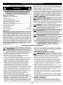
Manual
del Operador
MnN
2-Tiempos
WEEDWACKER® RECORTADOR
A GASOLINA
Model No. 316.791860
_BEL_EVABL_
STARTINO
EA S E _
*
*
*
*
*
SEGURIDAD
MONTAJE
FUNCIONAMIENTO
MANTENIMIENTO
LISTADO DE PIEZAS
PRECAUCION: Lea el manual
del operador y siga todas las
advertencias e instrucciones
de seguridad.
Sears, Roebuck
and Co., Hoffman
Estates, IL 60179, U.S.A.
Visite nuestro sitio web: www.sears.com/craftsman
769-03835A
3/08
PROPOSICION
Toda la informaci6n,las ilustracionesy las especificaciones contenidas en
este manual se basan en la informaci6n mas reciente disponible en el
momento de impresi6n del manual. Nos reservamos el derecho de hacer
cambios en cualquier momento sin aviso previo.
65 DE CALIFORNIA
LAS EMISIONES DEL MOTOR DE ESTE PRODUCTO CONTIENEN
SUBSTANCIAS QUlMICAS QUE EL ESTADO DE CALIFORNIA
CONOCE COMO CAUSANTES DECANCER, DEFECTOS DE
NACIMIENTO U OTROS DANOS REPRODUCTIVOS.
Los simbolos de seguridad se utilizan para Ilamar su atenci6n sobre
posibles peligros. Los simbolos de seguridad y sus explicaciones merecen
toda su atenci6n y comprensi6n. Los simbolos de seguridad no eliminan
ningun peligro por si mismos. Las instrucciones o advertencias que ofrecen
no substituyen las medidas adecuadas de prevenci6n de accidentes.
INDICE DE CONTENIDOS
Normas para una operacion segura .......................
E2
Garantia .............................................
E4
Conozca su unidad ....................................
E4
Instrucciones de ensamble ..............................
E4
Informacion del aceite y del combustible ...................
E5
Instrucciones de arranque y apagado .....................
E5
Instrucciones de operacion ..............................
E6
Instrucciones de mantenimiento y reparacion ...............
E7
Limpieza y almacenamiento
.............................
E8
Resolucion de problemas ...............................
E9
Especificaciones
.....................................
E10
Lista de piezas ......................................
E14
Numeros de servicio .........................
Contraportada
SIMBOLO
ALERTA
DE SEGURIDAD:
advertencia
o
precaucion. Debe
prestar atencion paraIndicapeligro,
evitarsufrir graves
lesiones
personales. Puede ser utilizadojunto con otros simbolos o figuras.
NOTA:
,_
PELIGRO: El no obedecer una advertenciade seguridad puede
conducir a que usted u otras personassufrangraves lesiones.Siga
siemprelas precaucionesde seguridad para reducirel riesgode
incendio, descargaelectricay lesionespersonales.
El no seguir una advertencia de seguridad
puede conducir a que usted u otras personas sufran lesiones.
Siga siempre las precauciones de seguridad para reducir el
riesgo de incendio, descarga electrica y lesiones personales.
NOTA:Para los usuariosen tierrasforestales de los EE.UU.y en losestados
de California,Maine, Oregon y Washington.Todos los terrenosforestales de
los EE.UU.y el estado de California(Codigos de RecursosPublicos4442y 4443),
Oregony Washington,requierenpor decreto,que ciertos motores de combustion
interna que se hagan funcionar en zonas boscosas y/o zonas cubiertas por
pastizales,esten equipados con un parachispas,que sean mantenidos en buen
estado de funcionamiento o que el motor sea construido, este equipado y sea
mantenido para evitar incendios. Consulte los reglamentos pertinentes a esos
requisitos con las autoridades estatales o locales. El incumplimiento de esos
requisitospuede responsabilizarleo someterlea laimposicion de unamulta. Esta
unidadfue equipada en lafAbricacon un parachispas. Si requieresustitucion,
hay una Pantalla Parachispas disponible, Pieza #753-05169 al contactar el
departamento de servicio.
• IMPORTANTE
I_I_
Le ofrece informacion o instrucciones que son esenciales
para la operacion o mantenimiento del equipo.
ADVERTENCIA:
PARAC H ISPAS
LEA TODAS LAS INSTRUCCIONES
SIGNIFICADO
PRECAUCION:
El no seguir una advertencia de
seguridad puede conducir a da_o patrimonial o a que usted
u otras personas sufran lesiones personales. Siga siempre
las precauciones de seguridad para reducir el riesgo de
incendio, descarga electrica y lesiones personales.
Lea el manual del operador y siga todas las advertencias e
instrucciones de seguridad. De no hacerlo, el operador y/o los
espectadores pueden sufrir graves lesiones.
SI TIENE PREGUNTAS, LLAME AL 1-800-659-5917
INFORMACION
ANTES DE LA OPERACION
DE SEGURIDAD •
alguien se le acerca, pare el motor y el accesorio de corte de inmediato.
• Esta unidad no fue dise_ada para ser usada como cortamalezas.
No conecte ni opere esta unidad con ningQn tipo de cuchilla ni
accesorio para cortar malezas.
ADVERTENCIAS DE SEGURIDAD A GASOLINA
I
reglas de seguridad. Lea estas instrucciones antes de operar la
unidad a fin de garantizar la seguridad del operador y cualquier
I ADVERTENCIA:
AI instrucciones
utilizar la unidad,
observar las
transeQnte. Guarde estas
paradebe
uso posterior.
i& i.ow....c..
"0asonaes
n'a a eIu
• Lea todas las instrucciones con cuidado. Conozca bien los
controles y el uso correcto de la unidad.
• No opere esta unidad siesta cansado, enfermo, o bajo los
efectos del alcohol, drogas o medicamentos.
• Los ni_os y los adolescentes menores de 15 a_os no deben operar
las unidades, excepto por los adolescentes guiados por un adulto.
• Inspeccione la unidad antes de utilizarla. Cambie las partes daSadas.
Verifiquesi existen perdidas de combustible. Asegurese de que los
sujetadores esten bien colocados y asegurados. Cambie las partes
accesorias de corte que esten quebradas, cascadas o daSadas de
cualquier forma. Asegurese de que el accesorio de corte esta bien
instalado y ajustado con firmeza. Asegurese de que laproteccion
accesoria de corte este bien conectada y colocada segun se recomienda.
• Use solo linea despiral Hassle Free TM XTRA QUIET. No use nunca
linea reforzada con metal, alambre, cadena ni soga, etc. Estas
pueden desprenderse y convertirse en un proyectil peligroso.
• Tenga en cuenta el riesgo de lesiones en la cabeza, manos y pies.
• Oprima el control del regulador y verifique que regrese
automAticamente a la posicion de minima. Haga todos los
ajustes o reparaciones antes de usar la unidad.
• Limpie el Area de corte antes de cada uso. Retireto(los los objetos como
rocas, vidrios rotos, clavos, alambre o cuerda los cuales pueden ser
despedidos o enredarse en el accesorio de corte. Aleje a to(los los niSos,
espectadores y animales domesticos. Mantenga todos los niSos,
espectadores y animales domesticos a un radio de por Io menos 50 pies
(15 m); aun asi puede existir un rieego de objetos despedidos contra los
espectadores. Los espectadores (:lebenusar protecci6n para sus ojos. Si
pueden explotar si se encienden. Tome lassiguientes precauciones:
• Guarde el combustible en envases que hayan sido dise_ados y
aprobados para el almacenamiento de dichos materiales.
• Antes de Ilenar el tanque de combustible, apague siempre el
motor y espere que se enfrie. No retire nunca la tapa del tanque
de combustible ni cargue combustible mientras el motor est6
caliente. No opere nunca la unidad sin la tapa del combustible
colocada firmemente en su lugar. Afloje la tapa del combustible
lentamente para disipar la presion del tanque.
• Mezcle y cargue el combustible en un Area exterior bien ventilada
donde no haya chispas ni llamas. Quite lentamente la tapa del
combustible solo despues de apagar el motor. No fume mientras
carga o mezcla el combustible. Limpie de inmediato todo el
combustible que se haya derramado.
• Evite crear una fuente de encendido por combustible derramado.
No arranque el motor hasta que se hayan disipado los vapores
del combustible.
• Aleje la unidad a por Io menos 30 pies (9.1 m.) del lugar de carga
de combustible antes de arrancar el motor. No fume, mantenga
las chispas y las llamas abiertas lejos del Area mientras carga el
combustible u opera la unidad.
DURANTE LA OPERACION
• No arranque ni opere la unidad en una sala o edificio cerrado. Los
gases de escape de mon6xido de carbono pueden ser letales en un
Area cerrada. Opere esta unidad s61oen un Area exterior bien ventilada.
E2
• Uselentes
ogafasdeproteccion
quecumplan
conlas
normas
ANSIZ87.1-1989,
yproteccion
parasusoidos/audicion
mientras
opereestaunidad.
Usesiempre
unamascara
facialo
paraprotegerse
contraelpolvosi laoperacion
levanta
polvo.
• Usepantalones
largos
ygruesos,
botas,
guantes
ycamisa
demanga
larga.
Nouseropaholgada,
alhajas,
pantalones
cortos,
sandalias
ni
estedescalzo.
Sostenga
elcabello
sobre
elniveldeloshombros.
• Laproteccion
accesoria
decortedebeestarsiempre
colocada
en
sulugarmientras
operelaunidad.
Nooperelaunidad
conlasdos
lineasdecorteextendidas,
y lalineacorrecta
instalada.
No
extienda
lalineadecortemasaliadelaIongitud
delaproteccion.
• Estaunidad
cuenta
conunembrague.
Elaccesorio
decorte
permanece
estacionario
cuando
elmotorestA
enmarcha
lenta.
Sino
Iohace,
hagaajustar
launidad
porunt6cnico
deservicio
autorizado.
• Ajuste
lamanija
enDasutama_o
demodo
quelebrinde
elmejor
agarre.
• AsegQrese
dequeelaccesorio
decortenoestAencontacto
con
ningQn
objetoantesdearrancar
launidad.
• Uselaunidad
Qnicamente
conlaluzdeldiaoconbuena
luzartificial.
• Evitearrancar
launidad
accidentalmente.
Coloquese
enposicion
deiniciosiempre
quetiredelacuerda
dearranque.
Eloperador
y
launidad
debenestarenunaposicion
estable
alcomenzar.
Lea
lasinstrucciones
deArranque
yApagado.
• Uselaherramienta
adecuada.
Nouseestaunidad
paraninguna
tareaparalacualnohasidodise_ada.
• Noseestiredemasiado.
Mantenga
siempre
unaposicion
y
equilibrio
adecuados.
• Sostenga
siempre
launidad
conambas
manos
mientras
esteen
funcionamiento.
Sostenga
confirmeza
tantoelmangocomola
manija
auxiliar.
• Mantenga
lasmanos,
lacaraylospieslejosdetodas
laspartes
moviles.
Nointente
tocarnidetener
elaccesorio
decortemientras
gira.
• Notoqueelmotor,
elbastidor
delengranaje
nielsilenciador.
Estaspartes
secalientan
mucho
conlaoperacion.
Luegode
apagar
launidad,
permanecen
calientes
durante
untiempo
breve.
• Noopereelmotora unavelocidad
mayorquelanecesaria
para
cortar,
recortar
orecortar
losbordes.
Nohagafuncionar
elmotor
aaltavelocidad
mientras
noestAcortando.
• SIMBOLOS
DE SEGURIDAD
• Apague
siempre
elmotorcuando
demore
elcorteo mientras
camina
entrezonas
decorte.
• Sigolpea
oseenreda
conalgQn
objeto
extra,o,
apague
elmotorde
inmediato
yverifique
sihayda_os.
Repare
todoslosda_os
antes
de
volver
aintentar
operar
launidad.
Noopere
launidad
sitienepiezas
flojas
oda_adas.
• Apague
elmotorpararealizar
todoelmantenimiento,
reparaciones
o cambio
delaccesorio
decorteu otrosaccesorios.
• Uses61o
piezas
yaccesorios
derepuesto
delfabricante
delequipo
original
para
estaunidad.
Puede
obtenerlos
ensuproveedor
deservicio
autorizado.
Elusodepiezas
yaccesorios
quenosonequipo
origina;
puede
causar
graves
lesiones
aloperador
oelda_odesuunidad,
yla
cancelaci6n
desugarantia.
• Mantenga
launidad
libredevegetacion
yotrosmateriales.
Pueden
alojarse
entreelaccesorio
decorteylaproteccion.
• Para
reducir
elriesgo
deincendio,
cambie
lossilenciadores
y
amortiguadores
dechispas
defectuosos,
mantenga
elmotor
yelsilenciador
libredepasto,
hojas,
grasa
excesiva
oacumulaciones
decarbono.
OTRAS ADVERTENCIAS DE SEGURIDAD
• No guarde nunca la unidad con combustible en el tanque en un edificio
donde los gases puedan Ilegar a una llama abierta o a una chispa.
• Espere que el motor se enfrie antes de guardar o transportar la
unidad. AsegQrese de que la unidad est6 segura al transportarla.
• Guarde la unidad bajo Ilave en un lugar adecuado y seco para
evitar que sea usada por personas no autorizadas y se da_e,
fuera del alcance de los ni_os.
• Nunca moje ni rode la unidad con agua ni con ningun otro liquido.
Mantenga las manijas secas, limpias y sin residuos. Limpie la unidad
luego de cada uso, lea las instrucciones de Limpieza y Almacenamiento
(p. Ea).
• Guarde estas instrucciones. ConsQItelas con frecuencia y
utilicelas para ense_ar a otros usuarios. Si le presta esta unidad a
alguien, prestele tambien estas instrucciones.
CONSERVE
E INTERNACIONALES
ESTAS INSTRUCCIONES
•
Este manual del operador describe los simbolos y figuras de seguridad e internacionales que pueden aparecer en este producto. Lea el
manual del operador para obtener informacion completa acerca de la seguridad, ensamble, operacion y mantenimiento y reparacion.
SIMBOLO
A
_
k
A,
_r[_ I [_
SIGNIFICADO
SIMBOLO
• LOS OBJETOS DESPEDIDOS Y LA CUCHILLA
ROTATIVA PUEDEN CAUSAR GRAVES LESIONES
,, SIMBOLO DE ALERTA DE SEGURIDAD
Indica peligro advertencia o precauci6n: Puede ser
utilizado junto Con otros simbolos o figuras.
ADVERTENCIA:
N0 opere esta unidad si la
protecci6n p!astica de linea no esta colocada en SUlugar.
Mantengase alejado del accesorio de corte giratorio.
ADVERTENCIA- LEA EL MANUAL DEL
OPERADOR
Lea el manual dei operador y siga todas las adVertencias
e instruociones de seguridadl De no hacerlo, el operador
los espectadores pueden sufrir graves lesiones.
ADVERTENCIA:
Mantenga a t0d0s !os espectadores,
" MANTENGA ALEJADOS A LOS ESPECTADORES
en especial a niSos y animales d0m6sticos a por Io menos
50 pies (15 m) del Area de corte.
objetos Yariojad0s
pot la unidad
t _ ,ADVERTENCIA:
USE PROTECCION Los
OCULAR
AUDITIVA
|
e! ruido fuerte pueden causar graves lesiones0cu!aresy
F perdida auditiva. Utilice protecci6n ocular que cumpla con las
normas ANSIZ8711--1989 y protecci6n auditivacuando opere
esta unidad. Use una caretacompleta cuando la necesite.
r_,_
.._I_
,,COMBUSTIBLE
|
|
CONTROLD
,, ADVERTENCl A DE CALIEN'rE
;
SIN PLOMO
I Use siempre combustib!e!imPio
SIGNIFICADO
__
I
No toque un silenciador ni un cilindro calientei Puede I
quemarse: Estas partes se calientan mucho con e! I
uso, Luego de apagarse pe[manecen ca entes
durante un corto tiempo.
I
* INDICADOR DE ACEITE
1...,=Y i
Consulte el manual del opeiador paia obtener informacion I
....
I acerca del tip° c°rrect° de aceite"
........
I
, nuevo y sin p!0mo I
E ENC EN DIDO Y APAGADO
DO/ARRANQUE
!MARCH
A
• CUCHILLA AFI_DA
._"lrl
ADVERTENCIA:
La protecci6n
I
de! accesorio de
corte contiene una cuchi!!a afilada. Para prevenir
graves es ones, no toque a ouch a.
E3
GARANTIA TOTAL DE CRAFTSMAN
Si este producto de Craftsman Professional falla debido a un defecto en el material o en la mano de obra dentro de un periodo de tres a_os
a partir de la fecha de compra, devuelvalo a cualquier tienda o Centro de Servicio de Piezas y Reparaciones Sears u otro establecimiento de
Craftsman en los Estados Unidos para que sea reparado sin costo alguno (o ser reemplazado si resulta imposible repararlo).
Esta garantia se aplica solamente durante 90 dias si este producto en algQn momento se utiliza para fines comerciales o de alquiler.
Esta garantia abarca SOLAMENTE los defectos en el material o en la mano de obra. Sears NO pagar_:
• Los articulos consumibles que se desgasten debido al uso normal dentro del periodo de garantia, tal como lineas de corte, filtros de aire o bujias.
• Las reparaciones necesarias debidas a accidente o por no operar o no mantener el equipo de acuerdo con todas las instrucciones provistas.
• Los mantenimientos preventivos o las reparaciones necesarias debido a mezcla incorrecta de combustible, combustible contaminado o viejo.
Esta garantia le concede a usted derechos legales especificos, y usted pudiera tener otros derechos que varian de un estado a otro.
Sears, Roebuck and Co., Hoffman Estates, IL 60179
Convenio de Protecci6n de Reparaci6n
Felicidades por haber realizado una compra inteligente. Su nuevo producto Craftsman@ esta dise_ado y fabricado para ofrecerle a_os de
funcionamiento confiable. Pero como todos los productos, es posible que sea necesario repararlo de vez en cuando. Ahi es cuando tener un
Convenio de Proteccion de Reparacion puede ahorrarle dinero y problemas.
Esto es Io que incluye el Convenio de Proteccion de Reparacion*:
[]
Servicio experto de nuestros 10,000 especialistas profesionales en reparaciones
[]
Servicio ilimitado y sin costo alguno por piezas y mano de obra en todas las reparaciones cubiertas
[]
Reemplazo del producto por un valor de hasta $1500 si el producto cubierto no se puede reparar
[]
Descuento del 10% en el precio regular del servicio, asi como de las piezas instaladas, que el convenio no cubra; igualmente, 10% de
descuento en el precio regular de comprobacion de mantenimiento preventivo
[]
Ayuda rapida per tel6fono - la Ilamamos Solucion Rapida - asistencia tecnica por tel6fono de un representante de Sears. Piense en
nosotros como si fu6ramos un "manual del usuario que habla".
Una vez que adquiera el Convenio de Proteccion de Reparacion, todo Io que necesita es hacer una simple Ilamada para programar el servicio
de reparacion. Puede Ilamar a cualquier hora del dia o de la noche, o hacer una cita de servicio por Internet.
El Convenio de Proteccion de Reparacion es una compra libre de riesgo. Si usted cancela por cualquier motivo durante el periodo de garantia
del producto, proporcionaremos un reembolso completo. O, un reembolso prorrateado en cualquier momento despu6s de que venza el
periodo de garantia del producto, iAdquiera hoy mismo su Convenio de Proteccion de Reparaci6n!
Aplican algunas limitaciones y exclusiones. Para obtener precios e informacibn adicional en los Estados Unidos, Ilame al 1-800-827-6655.
*La cobertura en Canada varia en algunos articulos. Para obtener todos los detalles, Ilame a Sears en Canada al 1-800-361-6665.
Servicio de Instalaci6n Sears
Para la instalacion de electrodomesticos,
abridores de puertas de garaje, calentadores de agua, y otros productos para el hogar por
profesionales de Sears, en los Estados Unidos o CanadA, Ilame al 1-800-4-MY-HOME®.
Control de encendido
Tapa del combustible
APLICACIONES
y apagado
Como recortadora;
• Corte de cesped y hierbas delgadas
• Recorte de bordes
• Recorte decorativo alrededor de arboles, cercos, etc.
Puede usar otros accesorios con la unidad. Lea la lista de accesorios.
Manija de la
cuerda de
arranque
Mango del
eje
Control del regulador
Manija en D
Adaptadorde
apoyo
Bastidor del
eje
Cubierta del silenciador /
filtro de aire
Convertible
Bombilla del cebador
TM
acoplador
Accesorio
Cuchilla
de corte
de linea
de code
Silenciador
Bujia de
encendido
Protector de corte
Hassle Free ®
E4
ADVERTENCIA:
latapa del
combustiblelentamente
para evitar lesionarseconSaque
elrociadodel
combustible.
Noopere nunca
la unidad sinlatapa del combustible firmemente colocada en su lugar.
AJUSTE DE LA MANIJA EN D
"\
1. Ubique la tuerca de mariposa en el
mango en forma de D. Aflojela
suficientemente para soltar el mango
en forma de D (Fig. 1).
NOTA" No quite la tuerca de
,,
mariposa, la arandela o el perno,
i
2. Gire el mango en forma de D hacia
',,
la posicion vertical anfrente de la
,,
cubierta del eje (Fig. 1).
_(,;
ii
3. Sostenga la unidad enla posicion
":'-'.--L\-_-L'.',';
de funcionamiento (Fig. 8). Si es
necesario, reubique el mango en
Fig. 1
forma de D hacia el punto que
ofrezca el mejor agarre.
4. Apriete la tuerca de mariposa hasta que el mango est6 seguro.
INSTALACION DEL ACCESORIO RECORTADOR
Antes del uso, la marca la fijacion segura de trimmer es instalada
correctamente. Refierase por favor a Operar el Convertible TM
Sistema de Acoplador para la instalacion apropiada.
NOTA: Quite la tapa roja o el gancho de la cubierta inferior del eje
antes de ensamblar al acoplador Convertible TM
\
ADVERTENCIA:
es muy Apague
inflamable.
Los el
gases pueden explotarLa sigasolina
se encienden.
siempre
motor y espere que se enfrie antes de cargar el tanque de
combustible. No fume mientras Ilena el tanque. Mantenga
las chispas y las llamas lejos del Area.
ADVERTENCIA:
Carguede
el combustible
en combustible
un Area exterior
limpia y bien ventilada. Limpie
inmediato todo
que se haya derramado. Evite crear una fuente de encendido con
el combustible derramado. No arranque el motor hasta que se
hayan evaporado los gases del combustible.
I_1
exterior bien ventilada. Los gases de escape de monoxido
ADVERTENCIA:
Useletales
esta unidad
solo cerrada.
en un Area
de carbono pueden ser
en un Area
I _lb
en posicion de inicio cuandotire de lacuerda de arranque (Fig.5).El
y la unidad deben
estar
en una posicionestable
al arrancar
I operador
ADVERTENOIA:
evite
losarranques
accidentales.Col6quese
la unidad para evitar graves lesionespersonales.
INSTRUCCIONES
INSTRUCCIONES PARA MEZCLAR EL ACEITE Y EL COMBUSTIBLE
El combustible viejo o mal mezclado son los motivos principales del
mal funcionamiento de la unidad. AsegOrese de usar combustible
nuevo, limpio y sin plomo. Siga las instrucciones en detalle para
mezclar correctamente el aceite y el combustible.
Definicibn de los combustibles de mezcla
Los combustibles actuales con frecuencia son una mezcla de gasolina y
oxigenantes como por ejemplo etanol, metanol o MTBE (eter).EI combustible
mezclado con alcohol absorbe agua. Una cantidad tan peque_a como el 1%
de agua en el combustible puede causar la separacion del combustible y el
aceite. Forma ficidos cuando estfi almacenado. Cuando use combustible
mezclado con alcohol, use combustible nuevo (de menos de 60 dias).
Uso de combustibles
de mezcla
Si usted opta por usar un combustible de mezcla o si su uso es
inevitable, tome las precauciones recomendadas.
• Use siempre una mezcla fresca de combustible segOn Io indica
su manual del operador.
• Agite siempre la mezcla de combustible antes de cargarlo en la unidad.
• Drene el tanque y haga funcionar el motor en seco antes de
guardar la unidad.
Uso de aditivos en el combustible
La botella de aceite de 2 ciclos que vino con su unidad contiene un aditivo
en elcombustible que ayudarfi a inhibir lacorrosi6n y a reducir la formaci6n
de dep6sitos de goma. Se recomienda que use s61oel aceite de 2 ciclos
con esta unidad. Si es inevitable, use un buen aceite de 2 ciclos elaborado
para motores enfriados por airejunto con un aditivopara el combustible
como por ejemplo el estabilizador de gasolina STA-BIL® o similar.Agregue
23 mL (0,8 onzas) de aditivo de combustible por gal6n de combustible de
acuerdo con las instrucciones del envase. NUNCA agregue aditivos
directamente en el tanque de combustible de la unidad.
A
]_
1.
2.
Para que el motor funcione correctamente
y con la mayor fiabilidad, preste mucha atenci6n alas
instrucciones de mezcla de aceite y combustible del envase de
aceite de 2 ciclos. El uso de combustible mezclado en forma
incorrecta puede da_ar seriamente el motor.
Mezcle bien la proporci6n correcta de aceite para motor de 2 ciclos y
gasolina sin plomo en una lata de combustible por separado. Use una
proporci6n de 40:1 de combustible y aceite. No los mezcle directamente
en eltanque de combustible de la unidad. Consulte las proporciones
especificas de mezcla de gasolina
y aceite enla tabla siguiente.
NOTA: 3,8 litros (un galon) de
gasolina sin plomo
mezclada con una
botella de 95 mL (3,2
onzas) de aceite de 2
ciclos es una
GASOLINA SIN
ACEITE DE 2
proporcion de 40:1 de
PLOMO
CICLOS
combustible y aceite.
NOTA: Elimine la mezcla vieja
95 mL
3,8 LITROS
de aceite y
(1 GALON de
(3,20NZAS
combustible de
EE.UU.)
FLUIDAS)
acuerdo con los
1 LITRO
25 mL
reglamentos federales
estatales y locales.
PROPORCION
Mezcle la gasolina con A_a_ado aO_
el aceite. Vea las
_, u
_ __/ff _/X-_"
Instrucciones para
.......
_-//
_ _-_
Mezclar el Aceite y el _ncenalao In)y/Y/d'
jJ
Oomb.st,
b,e
Llene eltanque de com-_
_\ (_
ibustible con la mezcla ) \
/
de combustible/aceite.
_\_/
NOTA: No hay necesidad de
_
J/f/'-_
girar la unidad.
Encendido/de parada
(_/"_-regulador
elcontrol (Fig.2) estfi
enla posici6n de
Fig. 2
trabajo siempre(I).
_3.
Oprimacompletamenteel
Bulbo cebador
cebador y sueltelo10
veces. Hfigalo lentamente.Se deberfi ver un
poco de combustible en el
cebador y en lastuberias
de alimentacionde
combustible (Fig.3).Si no
puedever elcombustible
en el cebador,oprimaloy
sueltelotantas veces
como sea necesariohasta
que vea combustibleen el
Fig. 3
mismo.
_
Posici6n de
4. Col6quese en la posici6n /_q_,_
Arranque
de arranque (Fig.4) y hale
el cord6n de arranque
_'P/M_I_
con energia hasta que el
_. rr_r_jLPun /
motor arranque. Espera
10 a 15 segundos,
entonces exprima la
vfilvula reguladora para
controlar el corte o la
velocidad que sopla.
Control del
NOTA: Launidad usa
regulador
INCREDI-PULL TM
Fig. 4
Io cual reduce
considerablemente el esfuerzo requerido para arrancar el
motor. Debe halar el cordon de arranque Io suficiente para oir
que el motor trata de arrancar. No es necesario halar el cordon
con energia: no hay fuerte resistencia al halar.Tenga en cuenta
que este metodo de arranque es muy diferente (y mucho mils
fficil) del que usted pudiera estar acostumbrado a usar.
SI... El motor no arranca, regrese al paso 3.
NOTA: Si la unidad estfi caliente y no Iograarrancar despu_s de halar
3 veces el cordon de arranque, apriete el control del obturador
y hale el cordon de arranque hasta que la unidad arranque.
INSTRUCCIONES DE APAGADO
1. Saque la mano del control del regulador. Deje enfriar el motor
en marcha en vacio.
2.
Coloque el control de encendido y apagado en posicion de
APAGADO (O)(Fig. 2).
] PRECAUCION:
]
]
]
]
DE ARRANQUE
DE LA MEZCLA = 40:1
E5
OPERACION
DEL SISTEMA
DEL ACOPLADOR
CONVERTIBLE
COMO SOSTENER EL RECORTADOR
TM
de'
des0aste
e'o'r,
i I.ow.. .C..'AntesdeiAo enz r uso,o
reste
oce
proteccion del pie y del cuerpo para reducir el riesgo de
lesion al funcionar esta unidad.
lea y comprenda el manual que viene con el accesorio. Siga toda I
la informaciSnde seguridad contenida en el mismo.
I
I _IL
I ADVERTENCIA:
Para
lesi°nes
pers°nales' I_
apague la unidad antes
de evitar
sacar graves
o instalar
accesorios.
I
El sistema del acoplador Convertible
accesorios optativos.
• Recortador de bordes de c6sped
• Cultivador
TM
le permite el uso de estos
• Turbo soplador
• Cortamalezas
• Sierra de poste
• Podadora con cuchilla circular
• Recortador de setos
COMO SACAR EL ACCESORIO DE CORTE U OTRO ACCESORIO
personales, apague la unidad antes de sacar o instalar
Para evitar graves lesiones
I_
I ADVERTENCIA:
accesorios.
1.
Gire la perilla en sentido
antihorario para aflojarla
Acoplador de
I
(Fig. 7).
ConvertibleT_
_._
Opima y sostenga el boton --|
&
-_[
de desconexion (Fig. 5).
3. A la vez que sujeta la caja
del eje superior, tire del
accesorio de corte o
cualquier otro accesorio
recto hacia afuera del
Hueco de guia
acoplador Convertible TM
Fig. 5
(Fig. 6).
INSTALACION DEL ACCESORIO DE CORTE U OTROS
ACCESORIOS
• Corte de derecha a izquierda siempre que sea posible. Cortar
hacia la izquierda mejora la eficiencia de la unidad. Los recortes
salen arrojados en sentido contrario al operador.
• Recorte Onicamente cuando el pasto y las hierbas esten secas.
• La vida de su linea de corte depende de:
• Seguir todas las tecnicas de corte indicadas anteriormente
• El tipo de vegetacion que corte
• El lugar donde se corta
Por ejemplo, la linea se desgastara m_is r_ipido cuando corte contra
un muro que cuando corte alrededor de un arbol.
RECORTE DECORATIVO
El recorte decorativo se realiza
eliminando toda la vegetacion de
alrededor de los Arboles, postes,
cercos, etc.
Gire toda la unidad a modo de que el
accesorio de corte se ubique a un
Angulo de 30 ° con el suelo (Fig. 9).
I
que el bot6n de la liberaci6n es chasqueado completamente
el hoyo primario (Fig.
6), yoperar
que laesta
perilla
(Fig. 7)
es seguro
apretado
I en
PRECAUCION:
Antes
unidad,
est&
firmemente.
NOTA:
1.
• El accesorio de corte esta paralelo al
suelo y hace facil
contacto con la vegetacion que va a
Fig. 8
ser cortada sin que el operador tenga
que inclinarse.
CONSEJOS PARA OBTENER MEJORES RESULTADOS AL
RECORTAR
• El angulo correcto para ubicar el accesorio de corte es paralelo al
suelo.
Botbn de desconexi6n
2.
I_ll
Antes de operar esta unidad, parese en
posicion de operacion (Fig. 8). Verifique Io
siguiente:
• El operador tiene proteccion ocular y
ropa adecuada.
• El brazo derecho esta levemente
doblado, y la mano estA sosteniendo
el mango del eje.
• El brazo izquierdo esta recto y la
mano sostiene la manija en D.
• La unidad esta debajo del nivel de la
cintura.
Para facilitar la instalacion o remocion de los
accesorios, coloque la unidad sobre el suelo
o sobre un banco de
Hoyo primario
trabajo.
Gire la perilla en sentido
antihorario para aflojarla
(Fig. 7).
PROGRAMA DE MANTENIMIENTO
J_
A la vez que sostiene
firmemente el accesorio
de corte u otro accesorio,
Bastidor del
Bastidor del
empOjelo derecho hacia
eje superior
eje inferior
el interior del acoplador
Fig. 6
Convertible TM hasta que
el boton de desconexion
Orificio lateral 90°
encaje solidamente en el
orificio principal (Fig. 6).
NOTA: La alineacion del
boton de
desconexi6n con el
hueco de guia
_P_rilla
facilitar_i la instalacion
(Fig. 5).
3.
Gire la perilla en sentido
Fig. 7
horario para ajustarla (Fig. 7).
Para realizar recortes decorativos con el accesorio de corte de
cabezal de linea u otro accesorio, trabe el boton de desconexion
del accesorio de corte u otro accesorio en el interior del agujero de
90 ° (Fig. 7).
2.
nunca realice manteni-miento ni reparaciones con la unidad
funcionando. Realicesiempre el mantenimiento y las reparaciones
con la unidad fria. Desconecte el cable de la bujia de encendido
para cerciorarse de que la unidad no arrancar&
Estos procedimientos requeridos para el mantenimiento deben ser
realizados con la frecuencia indicada en latabla. Deben ser incluidos como
parte de toda puesta a punto de cada temporada.
NOTA: Es posible que algunos procedimientos de mantenimiento
requieran herramientas o habilidades especiales. Si no
esta seguro sobre estos procedimientos, Ileve la unidad a
Sears o a otro proveedor de servicio calificado. Para m_s
informacion, Ilame al 1-800-4-MY-HOME ®.
NOTA:
E6
El mantenimiento, el reemplazo o la reparacion de los
dispositivos y del sistema de control de emisiones puede ser
realizado por Sears o por otra agencia de servicio calificada.
Para m_s informacion, Ilame al 1-800-4-MY-HOME ®.
Afindegarantizar
elrendimiento
mb_imo
desumotor,
pudiera
ser
necesaria
lainspecci6n
delalumbrera
deescape
delmotor
despues
de50
horas
deoperaci6n.
Siusted
notaperdida
deRPM,
unrendimiento
insuficiente
ounafaltageneral
deaceleraci6n,
pudiera
requerirse
este
servicio.
Siusted
considera
quesumotor
necesita
estainspecci6n,
consulte
conSears
uotraagencia
deservicio
calificada.
Para
mas
informaci6n,
Ilame
al1-800-4-MY-HOME®.
NOtratederealizar
este
proceso
usted
mismo
yaquepudiera
dafiar
elmotor
como
resultado
de
contaminantes
presentes
enelproceso
delimpieza
delalumbrera.
FRECUENCIA
MANTENIMIENTO
REQUERIDO
La linea que est6 instalada correctamente tendrA la misma
Iongitud en ambos lados.
NOTA" AI instalar la linea nueva, asegOrese de que la linea quede Io
mas uniforme posible. Cualquier variacion en la Iongitud
puede ocasionar que la unidad vibre excesivamente. Si esto
sucede, pare la unidad y asegOrese de que la linea este pareja.
NOTA" No descanse el JHassle-Free TM Cortando Cabeza en el
suelo mientras la unidad corre.
La linea puede cortarse por:
• Enredarse con un objeto extrafio
• Fatiga normal de la linea
• Intentar cortar hierbas gruesas y lefiosas
• Forzar la linea en objetos como paredes o postes de cercos.
NOTA" Durante el uso normal, la linea de corte puede desgastarse
disparejamente Io cual puede ocasionar exceso de
vibraciones en la unidad. Si esto se torna incomodo o
incontrolable, pare la unidad y cambie la linea. Vea las
Instrucciones sobre Reemplazo de la Linea mas arriba.
MANTENIMIENTO
DEL FILTRO DE AIRE
CONSULTE
Antes de
arrancar el motor
Llene el tanque de combustible
con la mezcla correcta de aceite
y combustible
p. E5
Cada 10 horass
Limpie y vuelva a aceitar el
filtro de aire
p. E7
Cada 25 horass
Examine el parachispas y limpielo
Inspeccione la condicion y la
separacion de la bujia de
encendido
p. E8
p. E8
Cada 50 horas
Inspeccione si la lumbrera de
escape y la rejilla del
parachispas estan tupidas u
obstruidas para garantizar los
niveles m&ximos de rendimiento
p. E8
REEMPLAZO
6.
iA
La condicion del filtro de aire
es importante para la
operacion de la unidad. Un
filtro de aire sucio limitara el
Tornillos,
flujo de aire y cambiara la
mezcla de combustible y aire
en el carburador. Esto con
frecuencia se confunde con
un carburador mal ajustado.
Verifique la condicion del filtro
de aire antes de ajustar el
tornillo de marcha lenta.
Consulte Mantenimiento del
Filtro de Aire.
Remocibn de la cubierta del
silenciador/filtro
de aire
DE LA LiNEA
Siempre uso Craftsman Hassle-Free TM XTRA QUIET la Linea
Espiral. Escoja el tamafio de la linea mejor convenido para el trabajo
en mano. Rojo coloro la linea es disefiada para cortar cesped y
pequefias hierbas. Negro coloro la linea es disefiada para cortar
cepillo mas grande de hierbas y luz.
NOTA: Antes de insertar la
nueva linea en los
Flecha
agujeros de la cabeza
de corte, identifique
los agujeros
adecuados. Siga las
directrices que se
indican en la placa de
deslizamiento de la
linea. No trate de
Deslicese Plato
quitarle la cabeza de
Fig. 10
corte a la unidad al
reemplazar la linea.
1. Quitele a la cabeza de
corte la linea vieja y la
placa de deslizamiento
de la linea.
2.
1,
2.
Limpie toda la superficie
de la cabeza de corte.
Reinstale la placa de
deslizamiento (Fig. 10):
Fig. 11
"A" cuando se usa medio
(rojo) o grande (negro)la
linea, o
"B" forra cuando se usa
con diametros mas
pequefios que medio
(rojo) la linea
NOTA" La placa de
deslizamiento de la
Fig. 12
linea se debe
reinstalar en la cabeza de corte antes de insertar la nueva
linea.
Inserte ambos extremos de su linea a trav6s de los agujeros
adecuados en el lado de la cabeza de corte (Fig. 11).
5.
Hale la linea y cerciorese de que la linea este contra el cubo y
que est6 totalmente extendida a trav6s de los tOneles de
posicionamiento (Fig. 12).
E7
Tornillos
Fig. 13
t
Saque los cuatro (4)
tornillos que sostienen la Filtriod _dor
cubierta del silenciador /
filtro de aire (Fig. 13). Use
un destornillador de
vastago piano o de broca
Torx N ° T20.
Fig. 14
Quite la tapa del motor al
empujarla hacia arriba y
halarla hacia atrAs. No la
fuerce.
Limpieza del Filtro de Aire
No mantener debidamente el
filtro de aire puede resultar en
funcionamiento inadecuado o
puede causar dafio
permanente a en el motor.
3.
4.
a aevita 0eaves
sooa
apague siempre su recortador y espere que se enfrie antes
de limpiarlo o realizar todo tipo de mantenimiento.
Fig. 15
1.
Saque la cubierta del
silenciador / filtro de aire.
Lea la seccion de
Remocion e Instalacion
de la cubierta del
silenciador / filtro de aire.
2.
Gire la tapa y ubique el
filtro de aire adentro.
Fig. 16
Saque el filtro de aire de adentro de la tapa del filtro de aire /
silenciador (Fig. 14).
3.
Lave el filtro con agua y detergente (Fig. 15). Enjuague bien el
filtro. Escurra el exceso de agua. D6jelo secar por completo.
4. Aplique
suficiente
aceite
limpioSAE30para
recubrir
ligeramente
el
filtro(Fig.16).
5. Apriete
elfiltropara
esparcir
yretirar
elexceso
deaceite
(Fig.17).
6. Cambie
elfiltrodeaire
dentro
delatapadelfiltrode
2.
I_
3.
Fig. 17
aire / silenciador (Fig. 13).
NOTA" Si opera la unidad sin el filtro de aire y el ensamble de la
cubierta del silenciador / filtro de aire, su garantia quedarA
ANULADA.
Reinstalacibn de la cubierta del silenciador/filtro
de aire
NOTA: El flujo de las emisiones puede ser en una direcci6n solamente:
APARTANDOSEdel motor. Preste mucha atenci6n a c6mo se
ensambla el silenciador, de modo que Io pueda volver a armar
exactamente como est& El no hacerlo asf dafiara a la unidad y
pudiera causar lesiones personales graves.
1. Quite el filtro de aire / tapa del silenciador. Ver Remocion de la
Tapa del Filtro / Silenciador.
2.
Localice el silenciador, pero no Io quite. Busque el tornillo en la
parte inferior del
silenciador (Fig. 18). Quite Cap6___del parachispas
Motor
el tornillo usando una
/Ranuras
4
Ilave torx No. 20 o un
5.
6.
7.
8.
9.
El motor podria dafiarse si
Cambie las bujias que
est6n rajadas, sucias o
deterioradas. Fije la
separacion de aire a
0,635 mm (0,025
pulgadas) utilizando un
• Espere que el motor se enfrie antes de su transporte.
• Drene el combustible de la unidad.
• Ajuste la tapa del combustible antes del transporte.
• Asegure la unidad durante su transporte.
LIMPIEZA
A
I_
I --
ADVERTENOIA:
Para evitar graves lesiones personales, I
I apague siempre su recortador y espere que se enfrie antes
I de limpiarlo o realizar cualquier tipo de mantenimiento.
I
Use un cepillo pequefio para limpiar la parte exterior de la unidad. No use
detergentes fuertes. Los limpiadores domesticos que contienen aceites
aromaticos como pino y lim6n, y con solventes como el queroseno pueden
dafiar el bastidor de plastico y la manija. Seque toda la humedad con un
patio suave.
ALMACENAMIENTO
_.,,_
_nta
_
Pa
I
Torm.of
_,-Z_._Z,_,
/
Leng0etas parachispassilenciador
Fig. 18
del parachispas. Dos
lengQetas actOan como
bisagras en el lado
derecho de la cubierta.
Abra con un golpe rapido la cubierta del parachispas, como si
fuera una puerta, y despu6s hale las lengQetas para sacarlas de
las ranuras del silenciador.
4.
raspe ni limpie los electrodos.
I ADVERTENCIA:
No limpie en
conel chorro
penetran pequefias particulas
cilindro.de arena, ni
calibrador (Fig. 19).
0,635 mm
Instale una bujia de
(0,025 in.)
encendido con la
t
separacion correcta en la
cabeza del cilindro.
Fig. 19
Ajuste girando la Ilave de casquillo de 5/8 pulg. en sentido
horario hasta que est6 ajustada sin huelgo.
Si usa una Ilave de torsion, ajuste a:
12,3-13,5 N.m (110-120 pulg..libras).
No ajuste demasiado.
TRANSPORTE
Coloque la cubierta del silenciador / filtro de airesobre la parte posterior
del carburador y del silenciador.Alinee los orificios de los tornillos.
2.
Inserte los cuatro (4)tornillos en los orificios de la cubierta del
silenciador / filtro de aire (Fig. 13)y ajustelos. No los ajuste demasiado.
MANTENIMIENTO DEL PARACHISPAS
Levante cuidadosamente
haciendo palanca el lado
destornillador
izquierdo de laplane.
cubierta
I
4.
1.
3.
Limpie alrededor de la bujia de encendido. Saque la bujia de
encendido de la cabeza del cilindro girando una Ilave de
casquillo de 5/8 de pulgada en sentido antihorario.
• No guarde nunca la unidad con combustible en el tanque donde
los vapores puedan Ilegar a una llama o chispa.
• Espere que el motor se enfrie antes de guardar la unidad.
• Guarde la unidad bajo Ilave para prevenir el uso por
personas no autorizadas y su dafio.
• Guarde la unidad en un Area seca y bien ventilada.
• Guarde la unidad fuera del alcance de los nifios.
ALMAOENAMIENTO
PROLONGADO
Con un destornillador de punta plana, levante cuidadosamente
haciendo palanca la rejilla del parachispas, sacAndola del
interior de la cubierta del parachispas.
Limpie la rejila del parachispas con un cepillo de cerdas metalicas.
Cambiela siesta dafiada o si no la puede limpiar completamente.
Reinstale la rejilla del parachispas, ajustandola en forma cefiida
de nuevo en la cubierta del parachispas.
Reinstale las dos lengQetas de la cubierta en las dos ranuras y
cierre la cubierta del parachispas con un golpe rApido.
Si planea guardar la unidad durante un largo periodo de tiempo,
siga el siguiente procedimiento para su almacenamiento.
1.
Vuelvaa colocar el tornillo que quit6 en el Paso2 y aprietele firmemente.
Reinstale la tapa del filtro de aire / silenciador.
Drene todo el combustible del tanque de combustible en un
recipiente que contenga la misma mezcla de combustible de 2
ciclos. No use combustible que haya permanecido guardado
durante mas de 60 dias. Deseche la mezcla vieja de combustible y
aceite de acuerdo a las regulaciones federales, estatales y locales.
2.
Arranque el motor y dejelo funcionar hasta que se ahogue. Esto
asegura que todo el combustible ha sido drenado del carburador.
3. Espere que el motor se enfrie. Retire la bujia de encendido y
coloque alrededor de 30 ml (1 onza) de cualquier aceite para motor
de 2 ciclos de buena calidad dentro del cilindro. Tire de la cuerda
de arranque lentamente para esparcir el aceite. Vuelva a instalar la
bujia de encendido.
NOTA: Saque la bujia de encendido y drene todo el aceite del
cilindro antes de intentar arrancar el recortador despu6s de
su almacenamiento.
parachispas no se aprieta fijamente se puede caer y causarle
I dafio
ADVERTENOIA:
si el cap6
de' parachispas
Y pantalla del I
a la unidad y posibles
lesiones
personales graves.
I _IL
AJUSTE DEL CARBURADOR
NOTA:
Los ajustes realizados sin cuidado pueden dafiar seriamente su
unidad. Contacte una Quemaduras u otro comerciante
calificado del servicio para hacer los ajustes de carburador.
Llame 1-800-4-MY-HOME ® para mas informaci6n.
CAMBIO DE LA BUJIA DE ENCENDIDO
Use una bujia de encendido Champion RDJ7Y (o similar). La
separaci6n correcta es de 0,635 mm (0,025 pulgadas). Retire la
bujia luego de cada 25 horas de operaci6n e inspeccione su estado.
1.
4,
Apague el motor y espere que se enfrie. Tome el alambre de la
bujia con firmeza y sAquelo de la bujia de encendido.
E8
Limpie bien la unidad e inspeccione para ver si existen partes
flojas o dafiadas. Repare o cambie las partes dafiadas y ajuste
los tornillos, tuercas o pernos que puedan estar flojos. La
unidad estA ahora lista para ser guardada.
CAUSA
ACCION
La bombilla de cebado no fue oprimida Io suficiente
Oprima la bombilla de cebado total de 10 veces
El combustible
Drene el tanque de gasolina / Agregue mezcla de combustible nueva
es viejo o esta mal mezclado
Parachispas obstruido
Limpie o cambie el parachispas
La temperatura
Hale el cordon de arranque hasta un maximo de 10-15 veces
exterior es por debajo de 32 ° C (90° F)
I=_N
ELvA
Co_n
[o]_=t
E_Eo_
I=LUJ
_[o,][o]_P'._I
=!_IhVAI
I_IhV_
r._l
El combustible
es viejo o esta mal mezclado
Drene el tanque con combustible/Agregue mezcla de combustible nueva
El combustible
es viejo o esta mal mezclado
Drene el tanque con combustible/Agregue mezcla de combustible nueva
El accesorio de corte esta atascado de hierba
Pare el motor y limpie el accesorio de corte
Parachispas obstruido
Limpie o cambie el parachispas
:111_v_
[e) lie]:! _[e]l / I:!_I:l,.'!,lJ3 [_]1:1_// :1 "Je)/ =_[_ r:le_l _:I: [eI_V:
El combustible
![e{e]-'_lIt:1."
es viejo o esta mal mezclado
Drene el tanque con combustible/Agregue mezcla de combustible nueva
El filtro de aire esta sucio
Limpie o cambie el filtro de aire
Parachispas obstruido
Limpie o cambie el parachispas
NECESITA MAS AYUDA?
Encont_ua
loa,_espuesta
_'_muc, ho ma_,}ex managemyhome_<em
- g_at_s!
_iiiiiiiiii
o Busqueestey todos
susdemosmanua[es
deproductos
en[inea.
° Obtengarespuestas
de nuestros
expertos
en productos
parae[hogan
o Redba un p[ande manten_m_ento
persona[_zado
parasu hogan
_iii!!i!i!i
¸
iiii
Encuentre
[a_nformad6n
y [asherram_entas
que[eayudar_n
en susproyectos
parasuhogar.
p_esentade
ti}
pe_ Sea_s
..........
;i::_÷
E9
hV_
loin
u[o)
:TfI
Tipo de motor .........................................................................................................................................................
Enfriado por aire, de 2 ciclos
Desplazamiento .........................................................................................................................................................................
32 cc (1,95 cu in)
R.RM. de velocidad minima ....................................................................................................................................................
2.600 - 3.600 rpm
R.RM. de operacion (Recortador) ......................................................................................................................................................
6.800+ rpm
Tipo de encendido ...................................................................................................................................................................
Electronic Ignition
Interruptor de encendido ..............................................................................................................................................................
Rocker Switch
Separacion de la bujia de encendido ...................................................................................................................................
0,635 mm (0,025 in)
Bujia de encendido ...........................................................................................................................................
Champion RDJ7Y o bujia similar
Lubricacion ........................................................................................................................................................
Mezcla de combustible y aceite
Proporcion de combustible - aceite ..............................................................................................................................................................
40:1
Carburador .................................................................................................................................................................
Diafragma, multiposicional
Arranque .............................................................................................................................................
Incredi-Pull TM Empezar el Auto Rebobina
Silenciador ....................................................................................................................................................................
Desviado con proteccion
Regulador .................................................................................................................................................................
Retroceso manual a resorte
Capacidad del tanque de combustible ....................................................................................................................................
384 ml (13 onzas)
I_J :INILV_l'.,l
UJU(.._o]
:i'L V:T_):_'-_'_o]-'t
[*)I fl :::[_o]_:m
J_
Bastidor del eje impulsor .....................................................................................................................
Tubo de acero (Craftsman Convertible TM)
Control del regulador .............................................................................................................................................................
Gatillo para el dedo
Peso de la unidad (sin combustible, con la manija en D, protector accesorio de corte y Hassle Free TM) .................................... 6 kg (14 libras)
Mecanismo de corte .................................................................................................................................................
Cabeza de Hassle Free IVTM
Bobina de linea ..................................................................................................................................
Linea Espiral Hassle Free TM XTRA QUIET
*
Toda las especificaciones contenidas en este manual se basan en la informacion mas reciente disponible en el momento de impresion
del manual. Nos reservamos el derecho de hacer cambios en cualquier momento sin aviso previo.
EIO
DECLARACION
DEGARANTiA
DECONTROL
DEEMISIONES
EVAPORATIVAS
DELAEPAPARA
CALIFORNIA
LosDerechos
yObligaciones
deUstedsegdnlaGarantfa
El Consejo de Recursos del Aire (Air Resources Board) de California, la Agencia de Protecci6n del Medic Ambiente (EPA)y Sears, Roebuck and Co. (Sears)
tienen el placer de explicar la garantia del sistema de control de emisiones en su motor "off-road" pequefio modelo del afio 2008 y posterior. En California
y los 49 estados, los nuevos motores "off-road" pequefios deben ser disefiados, construidos y equipados para que cumplan con las exigentes normas del
Estado contra el "smog". Sears debe garantizar el sistema de control de emisiones en el motor "off-road" pequefio de usted para los periodos de tiempo
que se indican a continuaci6n siempre y cuando no haya habido maltrato, negligencia o mantenimiento inadecuado de su motor "off-road" pequefio.
El sistema de usted de control de emisiones pudiera incluir piezas tales como el carburador o sistema de inyecci6n de combustible, el sistema de encendido
y el convertidor catalftico. Tambien pudiera incluir mangueras, correas, conectores y otros conjuntos relacionados con las emisiones.
Cuando exista una condici6n que este dentro de la garantfa, Sears reparara su motor "off-road" pequefio sin costo alguno para usted, incluyendo diagn6stico,
piezas y mano de obra.
Los motores "off-road" pequefios de12007 y posteriores estan garantizados por dos afios. Si alguna pieza de su motor relacionadacon emisiones es defectuosa,
Sears la reparara o la reemplazar&
Responsabilidades
del Propietario segQn la Garantia
Como propietario del motor "off-road" pequefio, usted es responsable de realizar el mantenimiento requerido que se indica en su manual del operador. Sears
recomienda que usted conserve todos los recibos que cubren el mantenimiento de su motor "off-road" pequefio, pero Sears no puede denegar la garantfa
solamente porque usted no tenga los recibos ni porque usted no pueda asegurar que se ha realizado todo el mantenimiento programado.
•
Sin embargo, como propietario del motor "off-road" pequefio, usted debera estar consciente de que Sears pudiera denegarle cobertura de la garantia si su
motor "off-road" pequefio o una piezadel mismo ha presentadofallas debido a maltrato,negligencia,mantenimientoinadecuadoo modificaciones no aprobadas.
•
Usted es responsable de presentar su motor "off-road" pequefio a un Centro de Servicio Autorizado por Sears tan pronto se detecte el problema. Las
reparaciones en garantfa deberan terminarse en un perbdo de tiempo razonable, no mayor de 30 dfas.
Si tiene alguna pregunta en relacion con sus derechos y responsabilidades de acuerdo con su garantia, deberA Ilamar al 1-800-4-MY-HOME ®.
Cobertura de la Garantia del Fabricante
•
•
•
•
•
•
•
•
•
•
El periodo de garantia comienza en la fecha en que se entrega el motor o el equipo al comprador del minorista.
El fabricante garantiza al propietario inicial, y a cada comprador subsiguiente, por un periodo de dos afios, que el motor no tiene defectos
en los materiales ni la mano de obra que ocasionen la falla de una pieza garantizada.
La reparacion o el reemplazo de una pieza garantizada se realizara sin costo alguno para el propietario en un Centro de Servicio Autorizado
por Sears. Para conocer la ubicacion mas cercana comuniquese con Sears Ilamando al 1-800-4-MY-HOME ®.
Cualquier pieza garantizada que no este programada para reemplazo, segun Io exige el mantenimiento, o que este programada solamente para inspecci6n
regular a los efectos de "Reparar o Reemplazar Segun sea Necesario" esta garantizada por el perbdo de garantfa. Cualquier pieza garantizada que este
programada para reemplazo segun Io exige el mantenimiento, estara garantizada por el perbdo de tiempo hasta el primer punto de reemplazo programado
para esa pieza.
No se le cobrara al propietario por el trabajo de diagn6stico que Ileve a la determinaci6n de que una pieza garantizada esta defectuosa, si el trabajo de
diagn6stico se Ileva a cabo en un Centro de Servicio Autorizado por Sears.
El fabricante es responsable de los dafios a otros componentes del motor causados por la falla de una pieza garantizada que este todavia en garantfa.
Las fallas ocasionadas debido a maltrato, negligencia o mantenimiento inadecuado no estan cubiertas por esta garantfa.
El uso de accesorios o piezas modiflcadas puede ser motivo para desestimar una reclamaci6n de garantfa. El fabricante no es responsable de cubrir fallas
de piezas garantizadas causadas por el uso de accesorios o piezas modiflcadas.
Para presentar una reclamaci6n, vaya a su Centro de Servicio Sears Autorizado mas cercano. Los servicios o reparaci6n por motivo de garantfa se
realizaran en todos los Centros de Servicio Sears Autorizados.
Cualquier pieza de reemplazo aprobada por elfabricante se puede usar al realizarcualquier mantenimiento o reparaci6n de piezas bajo garantfa relacionadas
con emisiones y se proporcionaran sin cargo alguno para el propietario. Cualquier pieza de reemplazo que sea equivalente en rendimiento o durabilidad
se puede usar en mantenimiento o reparaci6n sin garantfa y no reducira las obligaciones de garantfa del fabricante.
Lista de Piezas de Emisiones en Garantia
Los siguientes componentes se incluyen en la garantfa del motor relacionada con emisiones: filtro de aire, carburador, cebador, tuberfas de combustible,
recuperaci6n de combustible/flltro de combustible, m6dulo de encendido, bujfay silenciador.
DECLARACION DE GARANTiA DE CONTROL DE EMISlONES EVAPORATIVAS PARA CALIFORNIA
Los Derechos y Obligaciones
de Usted segQn la Garantia
El Consejo de Recursos del Aire (Air Resources Board) de California y Sears, Roebuck and Co. (Sears)tienen el placer de explicar la garantfa del sistema de
control de emisiones evaporativas en su motor "off-road" pequefio (tipo de equipo) modelo del afio 2007 y posterior. En California, los nuevos equipos que usen
motores "off-road" pequefios deben ser disefiados, construidos y equipados para que cumplan con las exigentes normas del Estado contra el "smog". Sears
debe garantizar el sistema de control de emisiones evaporativas en su motor "off-road" Lawn & Garden (para el cesped y el jardfn) pequefio para el perbdo
que se indica a continuaci6n siempre y cuando no haya habido maltrato, negligencia o mantenimiento inadecuado de su equipo.
Su sistema de control de emisiones evaporativas pudiera incluir piezas tales como: carburadores, tanques de combustible, tuberfas de combustible, tapas de
combustible, valvulas, recipientes, filtros, mangueras de vapor, abrazaderas, conectores y otros componentes relacionados. En el caso de los motores de 80
cc o menos, solamente el tanque de combustible est_ sujeto a los requisitos de la garantia de control de emisiones evaporativas de esta seccibn. El
desplazamiento de su motor "off-road" pequeho es de menos de 80 cc.
Cobertura de la Garantia del Fabricante
Este sistema de control de emisiones evaporativas esta garantizado por dos afios. Si cualquier pieza relacionada con las emisiones evaporativas de su equipo
es defectuosa, la pieza sera reparada o reemplazada por Sears.
Ell
Responsabilidades
delPropietario
segdnlaGarantia
•
Como propietario del motor "off-road" Lawn & Garden pequefio, usted es responsable de realizar el mantenimiento requerido que se indica en su manual
de propietario. Sears recomienda que usted conserve todos los recibos que cubren el mantenimiento de su Motor Lawn & Garden, pero Sears no puede
denegar la garantia solamente porque usted no tenga los recibos.
•
Sin embargo, como propietario del motor "off-road" Lawn & Garden pequefio, usted debera estar consciente de que Sears pudiera denegarle cobertura
de la garantia si su tanque de combustible ha presentado fallas debido a maltrato, negligencia, mantenimiento inadecuado o modificaciones no aprobadas.
•
Usted es responsable de presentar su tanque de combustible Lawn & Garden al centro de distribucidn o al centro de servicio de Sears tan pronto se detecte
el problema. Las reparaciones en garantia deberan terminarse en un periodo de tiempo razonable, no mayor de 30 dias. Si tiene alguna pregunta en
relaci6n con la cobertura de su garantia, debera comunicarse con Sears Ilamando al 1-800-4-MY-HOME ®.
Requisitos de la Garantia por Defectos
(a) El periodo de garantia comienza en la fecha en que se entrega el motor o el equipo a un comprador final.
(b) Cobertura General de la Garantia de Emisiones Evaporativas. El tanque de combustible debe estar garantizado al comprador final y a cualquier propietario
posterior en cuanto a que cuando se instal6 el sistema de control de emisiones evaporativas estaba:
(1) Disefiado, construido y equipado de forma tal que cumplia con todas la regulaciones aplicables; y
(2) Sin defectos en los materiales ni la mano de obra que ocasionen la falla de una pieza garantizada durante un periodo de dos afios.
(c) La garantia de las piezas relacionadas con las emisiones evaporativas sera interpretada como sigue:
(1) Cualquier pieza garantizada que no este programada para reemplazo segun requiere el mantenimiento en las instrucciones por escrito, debe estar
garantizada por el periodo de garantia definido en la subseccidn (b)(2).Si alguna de esas piezas falla durante el periodo de cobertura de lagarantia, debe
ser reparada o reemplazada por Sears. Cualquier pieza reparada o reemplazada bajo la garantia debe estar garantizada por un tiempo no menor que
el periodo de garantia restante.
(2) Cualquier pieza garantizada queen las instrucciones por escrito este programada solamente para inspeccidn regular, debe estar garantizada por el
periodo de garantia definido en la subsecci6n (b)(2).Una declaracidn en dichas instrucciones por escrito al efecto de "reparar o reemplazar segun sea
necesario" no reducira el pen'odo de cobertura de la garantia. Cualquier pieza reparada o reemplazada bajo la garantia debe estar garantizada por un
tiempo no menor que el periodo de garantia restante.
(3) Cualquier pieza garantizada que este programada para reemplazo, segun exige el mantenimiento en lasinstrucciones por escrito, debe estar garantizada
por el periodo de tiempo anterior al primer punto de reemplazo programado para esa pieza. Si la pieza falla antes del primer reemplazo programado, la
pieza debe ser reparada o reemplazapor Sears. Cualquier pieza reparada o reemplazada bajo la garantia debe estar garantizada por un tiempo no menor
que Io que resta del periodo anterior al primer punto de reemplazo programado para esa pieza.
(4) La reparacidn o el reemplazo de cualquier pieza garantizada bajo las disposiciones de garantia de este articulo se debe realizar sin costo alguno para
el propietario en una estacidn donde se hagan trabajos de garantia.
(5) Independientemente de las disposiciones de la subsecci6n (4) anterior, los servicios o reparaciones en garantia se deben proporcionar en centros de
distribucidn que esten franquiciados para prestar servicios a los motores o equipos en cuesti6n.
(6) No se debe cobrar al propietario por el trabajo de diagndstico para determinar que una pieza garantizada esta realmente defectuosa, siempre y cuando
dicho trabajo de diagndstico se Ileve a cabo en una estaci6n donde se hagan trabajos de garantia.
(7) Durante el periodo de garantia del sistema de control de emisiones evaporativas establecido en lasubseccidn (b)(2),Sears debe mantener un suministro
de piezas garantizadas suficiente para satisfacer la demanda esperada de dichas piezas.
(8) AI realizar cualquier mantenimiento o reparacidn en garantia se deben usar piezas de reemplazo aprobadas por el fabricante y se deben proporcionar
sin cargo alguno para el propietario. Tal uso no reducira las obligaciones de garantia del fabricante que emite la garantia.
(9) El uso de cualquier accesorio o pieza modificada sera motivo para desestimar una reclamacidn de garantia hecha en conformidad con este articulo. El
fabricante que emite la garantia no sera responsable, segun este Articulo, de garantizar fallas de piezas garantizadas causadas por el uso de un accesorio
o una pieza modificada.
(10) Sears proporcionara los documentos que describen los procedimientos o normas de la garantia, en un plazo de cinco dias habiles desde que los solicite
el Consejo de Recursos del Aire.
Lista de Piezas de Emisiones en Garantia
(1) Tanque de Combustible
Con cada motor o equipo nuevo se proporcionaran instrucciones por escrito para el mantenimiento y uso del sistema de control de emisiones evaporativas
por parte del propietario.
E12
E13
REPLACEMENT
PARTS
2-CYCLE
GAS TRIMMER
- MODEL
316.791860
[
@
Item
1
2
3
4
5
6
7
8
9
10
11
12
13
14
15
16
17
18
19
20
21
22
23
Part No.
753-05214
791-180350B
791-180351
753-05216
753-05215
791-610675
791-181860
791-683974B
753-05217
791-684451
753-05487
791-612134
753-04606
791-182612
791-181086
753-05219
791-145308
753-05091
753-05240
791-181525
753-05221
753-05769
791-182396
Description
Air Cleaner Assembly
Air Cleaner Filter
Carburetor Mounting
Choke Plate
Carburetor Assembly
Carburetor Gasket
Carb Mount Screw
Item
24
25
26
27
28
29
30
31
32
33
34
(includes 2 & 27)
Screw Assembly
(includes 6 & 16)
Primer and Hose Assembly
Carb Mount Assembly (includes 7, 10 & 11)
Reed Assembly
Carburetor Mount Gasket
Rear Mounting Pad
Fuel Tank Assembly (includes 14-16)
Fuel Cap Assembly
Fuel Return Line
Fuel Line Assembly
Front Mounting Pad
Shroud Extension & Stand (includes 27)
Flywheel Assembly
Spacer
ACL Lever Assembly
Starter Housing Assembly (includes 21,42 & 43)
Clutch Washer
Part No.
791-182369
791-153592
753-04497
791-181345
791-182519
753-04003
791-180217
753-05025
791-611063
753-05226
791-610311B
35
36
37
38
39
40
41
42
43
*
*
753-05169
753-04619
753-04620
753-04814
753-04367
753-04182
791-182723
753-05222
791-182474
753-1209
753-05227
*
791-181599
Description
Clutch Rotor
Clutch Drum
Clutch Cover
Cover Screw
Anti-Rotation
Screw
Clamping Screw
Clamping Nut
Wire Leads and Sleeve
Ground Tab
Module Assembly (includes 32)
Spark Plug
Muffler Assembly (includes 36 & 37)
Exhaust Gasket
Muffler Mounting Bolt Assembly
Cylinder Assembly (includes 40 & 41)
Piston and Rod Assembly
Cylinder Gasket
Cylinder Bolt
ACL Throttle Cable
ACL Screw
Piston Ring Set
Short Block Assembly
(includes 7, 19, 20, 34 & 38-41)
Clutch Springs (Qty. 2)
Items Not Shown
E14
Assembly
Assembly
Assembly (includes 27-30)
REPLACEMENT
Item
Part No.
1
2
3
4
5
6
7
8
9
10
11
12
13
14
15
16
17
18
19
20
21
22
23
*
753-04234
753-04119
791-182690
791-182405
753-04405
753-04344
753-05461
791-181587
753-1190
791-181981
791-182057
791-181617
753-04386
791-613300
791-182541
791-182200
753-05569
791-182195
791-145569
791-682061
791-182189
753-05489
753-05036
753-05038
Description
Throttle Housing Assembly (includes 2-4)
Throttle Trigger
Throttle Trigger Spring
Switch Assembly
Throttle Cable Assembly
Upper Drive Shaft Housing
D-Handle Assembly (includes 8)
D-Handle Hardware
Split Boom Coupler (includes 10-13)
Adjustment Knob (includes 13)
Screw
Bolt
Nut
Lower Flexible Drive Shaft
Lower Drive Shaft Housing
Shield Mount Screw Assembly
Gearbox Assembly
Gearbox Screw
Anti-Rotation Screw
Blade Assembly
Shield Assembly (includes 20)
Cutting Head Assembly (includes 23)
Cutting Head Cap
Tube of Line
Items Not Shown
E15
PARTS - MODEL 316.791860
2-CYCLE GAS TRIMMER
Your Home
For expert troubleshooting and home solutions advice:
anage
www.managemyhome.com
For repair - in your home - of all major brand appliances,
lawn and garden equipment, or heating and cooling systems,
no matter who made it, no matter who sold it!
For the replacement parts, accesspries and
owner's manuals that you need to do-it-yourself.
For Sears professional installation of home appliances
and items like garage door openers and water heaters.
1-800-4-MY-HOME
Call anytime,
®
(1-800-469-4663)
day or night (U.S.A. and Canada)
www.sears.com
www.sears.ca
Our Home
For repair of carry-in items like vacuums, lawn equipment,
and electronics, call anytime for the location of your nearest
Sears Parts & Repair Service
1-800-488-1222
(U.S.A.)
www.sears.com
To purchase
a protection
1-800-827-6655
Para pedir servicio
a domicilio,
1-800-SU-
(Canada)
www.sears.ca
on a product serviced
(U.S.A.)
1-800-361-6665
piezas:
HOGAR ®
1-800-469-4663
agreement
de reparaci6n
y para ordenar
Center
by Sears:
(Canada)
Au Canada pour service
en fran£;ais:
1-800-LE-FOYER
uc
(1-800-533-6937)
(1-888-784-6427)
® Registered Trademark / TMTrademark / SM Service Mark of Sears Brands, LLC
® Marca Registrada / TMMarca de F_brica / SMMarca de Servicio de Sears Brands, LLC
MCMarque de commerce / MDMarque d6pos6e de Sears Brands, LLC
i
www.sears.ca
® Sears Brands, LLC