1
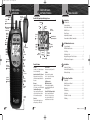
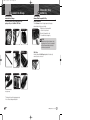
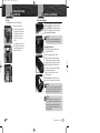
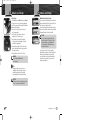
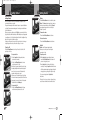
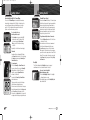
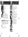
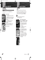
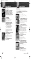
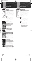
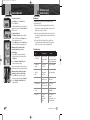
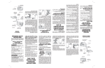
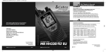
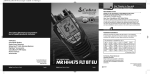
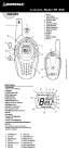
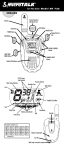
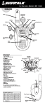
400-BR-F
6/23/04
2:09 PM
Page 1
Introduction
Our Thanks to You and
Customer Assistance
Thank you for purchasing a CobraMarine™ VHF radio.
Properly used, this product will give you many years
of reliable service.
How Your CobraMarine™ VHF Radio Works
Owner’s Manual
This radio is a battery powered portable transceiver for use afloat. It gives you
2-way vessel-to-vessel and vessel-to-shore station communications, primarily
for safety and secondarily for navigation and operational purposes. With it, you
can call for help, get information from other boaters, talk to lock or bridge tenders
and make radiotelephone calls to anywhere in the world through a marine operator.
Customer Assistance
Customer Assistance
Should you encounter any problems with this product, or not understand
its many features, please refer to this owner’s manual. If you require further
assistance after reading this manual, please contact your local dealer.
The Cobra Electronics Corporation
line of quality products includes:
™
This equipment is intended for use in:
a
❑ AT
a
❑ BE
CB Radios
a
❑ CZ
❑ CY
microTALK® Radios
❑ DE
a
❑ DK
a
❑ EE
a
❑ ES
Radar/Laser Detectors
Safety Alert® Traffic Warning Systems
GPS (Global Positioning System)
HighGear® Accessories
CobraMarine™ VHF Radios
Power Inverters
Nothing comes close to a Cobra®
For more information or to
order any of our products,
please visit our website:
www.cobra.com
English
Printed in China Part No. 480-119-P
Accessories
a
❑ LT
a
❑ LV
a
❑ LI
a
❑ LU
a
❑ MT
a
❑ NL
a
❑ NO
a
❑ PL
a
❑ PT
a
❑ SE
a
❑ CH
a
❑ SK
❑ SI
❑ TR
For Warranty, Product Service and
Accessory Information
Please contact your local dealer or distributor.
See the enclosed leaflet that provides contact
information for the CobraMarine™ international
distributors.
VHF MARINE RADIO
©2004 Cobra Electronics Europe Limited
Dungar House
Northumberland Avenue
Dun Laoghaire
County Dublin, Ireland
www.cobra.com
MR HH400 EU
Nothing comes close to a Cobra®
a
❑ FI
a
❑ FR
a
❑ GB
a
❑ GR
a
❑ HU
a
❑ IE
a
❑ IS
a
❑ IT
English
A1 English
400-BR-F
6/23/04
2:09 PM
Page A2
Radio Controls
and Indicators
Introduction
Antenna
Squelch
Knob
Backlit LCD Screen
and Product Features
Introduction
Belt Clip
Engagement
Knob
Backlit LCD (Liquid Crystal Display) Screen
Introduction
•
Tri Watch
Icon
Channel
Numbers
Scan
Icon
On-Off Power/
Volume Knob
Backlight/
Key Lock
Button
High/Low
Power Icons
Transmit
Icon
Transmit/Received
Signal Strength Icons
Table of Contents
Introduction
Our Thanks to You . . . . . . . . . . . . . . . . . . . . . . . . . . . . . . . . . . . . . . . A1
Customer Assistance . . . . . . . . . . . . . . . . . . . . . . . . . . . . . . . . . . . . . A1
Radio Controls and Indicators . . . . . . . . . . . . . . . . . . . . . . . . . . . . . . A2
Backlit LCD Screen . . . . . . . . . . . . . . . . . . . . . . . . . . . . . . . . . . . . . . . A3
Product Features . . . . . . . . . . . . . . . . . . . . . . . . . . . . . . . . . . . . . . . . A3
Important Safety Information . . . . . . . . . . . . . . . . . . . . . . . . . . . . . . . . 2
Recommendations for Marine Communication . . . . . . . . . . . . . . . . . . 5
Talk
Button
Channel
Up/Down
Buttons
Wrist
Strap
Connector
UIC Button
Memory
Button
High/Low
Power Button
Scan
Button
Backlit
LCD Screen
Speaker/
Microphone
Instant
Channel
16 Button
Tri-Watch
Button
Charging
Contacts
A2 English
Battery
Power Icon
VHF Marine Radio Protocols
Licensing Information . . . . . . . . . . . . . . . . . . . . . . . . . . . . . . . . . . . . . . 6
VHF Marine Radio Procedures . . . . . . . . . . . . . . . . . . . . . . . . . . . . . . . 7
Voice Calling . . . . . . . . . . . . . . . . . . . . . . . . . . . . . . . . . . . . . . . . . . . . . 8
Radiotelephone Calls . . . . . . . . . . . . . . . . . . . . . . . . . . . . . . . . . . . . . . 9
Emergency Messages and Distress Procedure . . . . . . . . . . . . . . . . . . 10
VHF Marine Channel Assignments . . . . . . . . . . . . . . . . . . . . . . . . . . . 14
U-I-C Active
Channel Map
Icons
Button
Lock
Icon
Battery
Compartment
Memory
Location
Number
Simplex
Operation
Icon
Memory Icon
Product Features
Dual Power
Selectable to 1 or 5 watts output power
for near or distant calling.
International/Canada/U.S.A. Channels
Allows operation on any of the three
different channel maps established for
these areas.
Waterproof
Submersible to 1 metre of water
for 30 minutes — meets JIS7 Standards.
Channel Scan/Memory Scan
Lets you scan through all channels or
up to ten selected memory locations
to find conversations in progress.
Button Lock
Prevents accidental changes to your
settings when you set this feature.
A3 English
•
Instant Channel 16
Instant access to priority Channel 16.
Tri-Watch
Lets you monitor three channels
at once — Channel 16 and two user
programmable channels.
Six AA Rechargeable
NiMH Batteries Included
Provides extended operating time
compared to alkaline batteries with
no memory effect.
Drop-in AC/DC Desk Charger Included
Lets you charge the batteries right
in the radio — at home, in your car
or in your boat. In addition, a UKcompatible connector is included.
Installation
Included in this Package . . . . . . . . . . . . . . . . . . . . . . . . . . . . . . . . . . . 25
Antenna, Wrist Strap and Belt Clip . . . . . . . . . . . . . . . . . . . . . . . . . . . 26
Batteries and Charger . . . . . . . . . . . . . . . . . . . . . . . . . . . . . . . . . . . . . 27
Operating Your Radio
Getting Started . . . . . . . . . . . . . . . . . . . . . . . . . . . . . . . . . . . . . . . . . . 30
Standby/Receive and Transmit . . . . . . . . . . . . . . . . . . . . . . . . . . . . . . 34
Advanced Operation . . . . . . . . . . . . . . . . . . . . . . . . . . . . . . . . . . . . . . 36
Maintenance . . . . . . . . . . . . . . . . . . . . . . . . . . . . . . . . . . . . . . . . . . . . 43
Troubleshooting . . . . . . . . . . . . . . . . . . . . . . . . . . . . . . . . . . . . . . . . . 43
Specifications . . . . . . . . . . . . . . . . . . . . . . . . . . . . . . . . . . . . . . . . . . . 44
Declaration of Conformity . . . . . . . . . . . . . . . . . . . . . . . . . . . . . . . . . . 45
CE Marking . . . . . . . . . . . . . . . . . . . . . . . . . . . . . . . . . . . . . . . . . . . . . 45
Nothing comes close to a Cobra®
1
400-BR-F
6/23/04
Introduction
2:09 PM
Page 2
Important Safety Information
Important Safety Information
™
Before assembling and using your CobraMarine VHF radio,
please read these general precautions and warnings.
Warning and Caution Statements
To make the most of this radio, it must be assembled and used properly.
Please read the assembly and operating instructions carefully before assembling
and using it. Special attention must be paid to the WARNING and CAUTION
statements in this manual.
WARNING
Statements identify conditions that could result in personal injury or loss of life.
CAUTION
Statements identify conditions that could cause damage to the radio
or other equipment.
Introduction
•
Important Safety Information
General Precautions
The following WARNINGS and CAUTIONS will make you aware of RF exposure
hazards and how to assure you operate the radio within the recommended RF
exposure limits established for it.
WARNINGS
Your CobraMarine™ radio generates electromagnetic RF (radio frequency)
energy when it is transmitting. To ensure that you and those around you are
not exposed to excessive amounts of that energy (beyond recommended
allowable limits for occupational use):
ALWAYS hold the radio, especially the antenna, at least 5 cm away from
you when you are transmitting.
NEVER allow the antenna to touch any part of your body when transmitting.
KEEP the radio and antenna at least as far from bystanders as from yourself.
DO NOT operate the radio without the supplied antenna or a Cobra Electronics
Corporation™ authorized replacement attachment. In addition to the RF energy
exposure hazard, doing so may damage the radio.
DO NOT transmit more than 50% of the time the radio is in use — 50%
duty cycle. The radio is transmitting when the Talk button is pressed and
the Transmit icon shows on the LCD screen.
ALWAYS use only Cobra Electronics Corporation™ authorized accessories
(antennas, batteries, belt clips, etc.).
DO NOT operate the radio where RF energy generated during transmission
may cause electromagnetic interference or incompatibility with other devices
or systems. This includes aircraft, blasting sites and hospitals.
TURN OFF the radio in explosive atmospheres and where signs are posted
prohibiting radio transmissions.
Failure to observe any of these warnings may cause you to exceed
recommended RF exposure limits or create other dangerous conditions.
2
English
Nothing comes close to a Cobra®
3
400-BR-F
6/23/04
2:09 PM
Page 4
Important Safety Information
Introduction
CAUTIONS
Your radio is only waterproof when the antenna and batteries
are properly installed.
Introduction
Recommendations for
Marine Communication
Recommendations for Marine Communication
•
AVOID using or storing the radio at temperatures below -20˚C
or above 60˚C.
The frequencies your radio uses are set aside to enhance safety afloat and for vessel
navigation and operational messages over a range suitable for nearshore voyages. If the
5 watt maximum output of your radio isn’t sufficient for the distances you travel from
the coast, consider installing a CobraMarine™ fixed mount radio with up to 25 watts of
output power. (Visit www.cobra.com or your local dealer for model availability.)
KEEP your radio at least 1 m away from your vessel’s magnetic
navigation compass.
If you will be going far offshore, you should consider adding even more powerful
radio equipment such as HF single side band or satellite radio for your vessel.
DO NOT attempt to service any internal parts yourself. Have any
necessary service performed by a qualified technician.
The coastguard does not endorse mobile phones as substitutes for marine radios.
They generally cannot communicate with rescue vessels and, if you make a distress
call on a mobile phone, only the party you call will be able to hear you. Additionally,
mobile phones may have limited coverage over water and can be hard to locate. If
you don’t know where you are, the coastguard will have difficulty finding you if
you’re using a mobile phone.
This radio is supplied with six NiMH (Nickel-Metal Hydride)
rechargeable batteries.
■
Use only the CobraMarine™ charger to recharge
NiMH batteries in the radio.
■
Do not short circuit the battery pack.
■
When replacing the batteries, dispose of the old batteries properly.
NiMH batteries may explode if disposed of in a fire.
■
The charger is to be used for charging purposes only.
It is not to be used during normal operation.
However, mobile phones can have a place on board where mobile coverage
is available — to allow social conversations and keep the marine frequencies
uncluttered and available for their intended uses.
Changes or modifications to your radio MAY VOID its compliance with
government rules and make it illegal to use.
4
English
Nothing comes close to a Cobra®
5
400-BR-F
6/23/04
2:09 PM
VHF Marine Radio Protocols
Page 6
Licensing Information
Licensing Information
The radio operates on all currently allocated marine channels and is switchable for
use according to International, Canadian or U.S.A. regulations. It features instant
access to emergency Channel 16 by pressing one key.
CobraMarine™ VHF radios comply with the U.S. FCC (Federal Communications
Commission) requirements that regulate the Maritime Radio Service.
VHF Marine Radio Protocols
•
Station License
The UK requires a ships radio license and a marine radio operator’s certificate before
transmitting equipment can be used aboard a vessel. Other European countries have
specific requirements of their own.
For detailed information and applications, contact the Radio Licensing Centre run
by Royal Mail in the UK. In other countries contact the relevant national postal or
telecommunications authority.
Canadian or U.S.A. Station License
If your vessel will be entering the sovereign waters of Canada or the U.S.A., you
should contact Industry of Canada, Radio Regulatory Branch or the U.S. Federal
Communications Commission for licensing and operating information.
Radio Call Sign
A radio call sign is included as part of the ships radio license in the UK.
Other countries may have different practices; contact your local regulatory
authority for information.
User Responsibility and Operating Locations
All users are responsible for observing domestic and foreign government regulations
and are subject to severe penalties for violations. The VHF frequencies on your radio
are reserved for marine use and require a special license to operate from land,
including when your boat is on its trailer.
VHF Marine Radio Procedures
VHF Marine Radio Procedures
•
Maintain Your Watch
Whenever your boat is underway, the radio must be turned On and
be tuned to Channel 16 except when being used for messages.
Power
Try 1 watt first if the station being called is within a few kilometres. If there
is no answer, switch to a higher power. This will conserve your battery
and minimize interference to other users.
Calling Coast Stations
Call a coast station on its assigned channel. You may use Channel 16
when you do not know the assigned channel.
Calling Other Vessels
Call other vessels on Channel 16. You may also call on ship-to-ship channels
when you know that the vessel is listening on a ship-to-ship channel.
Limits on Calling
You must not call the same station for more than 30 seconds at a time.
If you do not get a reply, wait at least 2 minutes before calling again.
After three calling periods, wait at least 15 minutes before calling again.
Change Channels
After contacting another station on a calling channel, change immediately
to a channel which is available for the type of message you want to send.
Station Identification
Identify your station by your call sign, ship name or other official number
at both the beginning and end of each message.
Prohibited Communications
You MUST NOT transmit:
6
English
■
False distress or emergency messages.
■
Messages containing obscene, indecent or profane words or meaning.
■
General calls, signals or messages (messages not addressed to a particular
station) on Channel 16, except in an emergency or if you are testing your radio.
■
When you are on land.
Nothing comes close to a Cobra®
7
400-BR-F
6/23/04
2:09 PM
VHF Marine Radio Protocols
Page 8
Voice Calling
Voice Calling
VHF Marine Radio Protocols
•
To call another vessel or a shore installation such as a lock or bridge tender:
■
Make sure your radio is On.
■
Select Channel 16 and listen to make sure it is not being used.
■
When the channel is quiet, press the Talk button and call the ship you
wish to contact. (Hold the radio at least 5 cm from your face and speak
directly into it in a normal tone of voice — clearly and distinctly.) Say
“[name of station being called] THIS IS [your vessel’s name or call sign]”.
■
Once contact is made on the calling channel, you must switch to a proper
working channel. See the channel listing on page 14 – 23.
For Example
Radiotelephone Calls
Radiotelephone Calls
•
Boaters may make and receive radiotelephone calls to and from any number on
the telephone network by using the services of public coast stations. Calls can be
made — for a fee — between your VHF radio and telephones on land, sea and in the
air. See pages 14 – 23 for the public correspondence (marine operator) channels.
If you plan to use these services, consider registering with the operator of the
public coast station that you plan to work through. Those services can provide
you with detailed information and procedures to follow.
CAUTION
You may disclose privileged information during a radiotelephone call.
Keep in mind that your transmission is NOT private, as it is on a regular
telephone. Both sides of the conversation are being broadcast and can be
heard by anyone who has a radio and tunes to the channel you are using.
The vessel Corsair calling the vessel Vagabond:
Corsair: “Vagabond, this is Corsair.”
Vagabond: “Corsair, this is Vagabond. Reply 72 (or any proper working channel).”
Corsair: “72.” or “Roger.”
■
After communications are completed, each vessel must sign off with its
call sign or vessel name and switch to Channel 16.
NOTE
For the best sound quality at the station you’re calling, hold the radio
at least 5 cm from your mouth and slightly off to one side. Speak in
a normal tone of voice.
8
English
Nothing comes close to a Cobra®
9
400-BR-F
6/23/04
2:09 PM
VHF Marine Radio Protocols
Page 10
Emergency Messages
and Distress Procedure
Emergency Messages and Distress Procedure
The ability to summon assistance in an emergency is the primary reason
to have a VHF marine radio. The marine environment can be unforgiving,
and what may initially be a minor problem can rapidly develop into a
situation beyond your control.
The coastguard monitors Channel 16, responds to all distress calls,
and coordinates all search and rescue efforts. Depending on the availability
of other capable vessels or commercial assistance operators in your vicinity,
coastguard or coastguard auxiliary craft may be dispatched.
In any event, do communicate with the coastguard as soon as you experience
difficulties and before your situation becomes an emergency. Use the emergency
message procedures only after your situation has become grave or you are faced
with a sudden danger threatening life or property and requiring immediate help.
If you are merely out of fuel, do not send an emergency message. Drop your
anchor and call a friend or marina to bring the fuel you need or give you a tow.
VHF Marine Radio Protocols
•
Emergency Messages
and Distress Procedure
Marine Emergency Signals
The three spoken international emergency signals are:
MAYDAY
The distress signal MAYDAY is used to indicate that a station is threatened
by grave and imminent danger and requests immediate assistance.
PAN PAN
The urgency signal PAN PAN is used when the safety of the vessel or person
is in jeopardy. (This signal is properly pronounced pahn-pahn.)
SECURITE
The safety signal SECURITE is used for messages about the safety of navigation or
important weather warnings. (This signal is properly pronounced see-cure-it-tay.)
When using an international emergency signal, the appropriate
signal is to be spoken three times prior to the message.
If You Hear a Distress Call
You must give any message beginning with one of these signals priority
over any other messages. ALL stations MUST remain silent on Channel 16
for the duration of the emergency unless the message relates directly to
the emergency.
If you hear a distress message from a vessel, stand by your radio. If it is
not answered, YOU should answer. If the distressed vessel is not nearby,
wait a short time for others who may be closer to acknowledge. Even if
you cannot render direct assistance, you may be in a position to relay
the message.
10 English
Nothing comes close to a Cobra® 11
400-BR-F
6/23/04
2:09 PM
VHF Marine Radio Protocols
Page 12
Emergency Messages
and Distress Procedure
Marine Distress Procedure
Speak slowly — clearly — calmly.
1. Make sure your radio is On.
VHF Marine Radio Protocols
Emergency Messages
and Distress Procedure
Keep the radio nearby. Even after your message has been received, the coastguard can
find you more quickly if you can transmit a signal for a rescue boat to home in on.
For Example
2. Select VHF Channel 16.
“Mayday — Mayday — Mayday”
3. Press Talk button and say:
“MAYDAY — MAYDAY — MAYDAY”
(or “PAN PAN — PAN PAN — PAN PAN”
or “SECURITE — SECURITE — SECURITE”)
“This is Corsair — Corsair — Corsair”
4. Say:
“THIS IS [your vessel name or call sign].”
“Struck submerged object and flooding — need pump and tow”
5. Say:
“MAYDAY” (or “PAN PAN” or “SECURITE”)
[your vessel name or call sign].
“Estimate we will remain afloat one-half hour”
6. Tell where you are:
(Your position or what navigational aids or landmarks are near.)
7. State the nature of your distress.
8. State the kind of assistance needed.
9. Give number of persons aboard and conditions of any injured.
“Mayday Corsair”
“Point Lynas bears 220 degrees magnetic — distance 5 kilometres”
“Four adults, three children aboard — no one injured”
“Corsair is an 8 metre sloop with blue hull and tan deck house”
“I will be listening on Channel 16”
“This is Corsair”
“Over”
It is a good idea to write out a script of the message form and post it where you
and others on your vessel can see it when an emergency message needs to be sent.
10. Estimate present seaworthiness of your vessel.
11. Briefly describe your vessel (length, type, colour, hull).
12. Say:
“I WILL BE LISTENING ON CHANNEL 16.”
13. End message by saying:
“THIS IS [your vessel name or call sign] OVER.”
14. Release Talk button and listen. Someone should answer.
If not, repeat the call, beginning at item 3 above.
For medical problems such as crew hit by sailboat boom or heart
trouble, make a PAN PAN call as above with the word medico added.
“PAN PAN MEDICO — PAN PAN MEDICO — PAN PAN MEDICO”
The coastguard will try to link you to a doctor who can give
expert advice and evaluate the need for evacuation.
12 English
Nothing comes close to a Cobra® 13
400-BR-F
6/23/04
2:09 PM
VHF Marine Radio Protocols
Page 14
VHF Marine
Channel Assignments
VHF Marine Channel Assignments
Three sets of VHF Channel Maps have been established for marine use
internationally, in Canada and in the U.S.A. Most of the channels are the
same for all three maps, but there are definite differences (see table on
the following pages). Your radio has all three maps built into it and will
operate correctly in whichever area you choose. When shipped from
the factory, your radio will be set to the International Channel Map.
(See page 32 for instructions on how to change the Channel Map.)
The following is a brief outline of the channel assignments in the
International Channel Map.
Distress, Safety and Calling
VHF Marine Radio Protocols
•
VHF Marine
Channel Assignments
Commercial
Channels 8, 9, 10, 11, 17, 67, 88, 88A
Working channels for working ships only. Messages must be about business or
needs of the ship. Use Channels 8, 67, 88 and 88A only for ship-to-ship messages.
Public Correspondence (marine operator)
Channels 1, 2, 3, 4, 5, 7, 23, 24, 25, 26, 27, 28, 60, 61,
62, 63, 64, 65, 66, 78, 82, 84, 85, 86, 87, 88
For calls to marine operators at public coast stations. You can make and receive
telephone calls through these stations.
Port Operations
Channel 16
Getting the attention of another station (calling) or in emergencies
(distress and safety).
Channels 4, 5, 7, 12, 14, 18, 19, 20, 21, 22, 61, 62,
63, 64, 65, 66, 69, 71, 73, 74, 77, 79, 80, 81, 82, 83
Used for directing the movement of ships in or near ports, locks or waterways.
Messages must be about operational handling, movement and safety of ships.
Intership Safety
Navigational
Channel 6
Ship-to-ship safety messages and for search and rescue messages to
coastguard ships and aircraft.
Channels 13, 67
Channels are available to all vessels. Messages must be about navigation,
including passing or meeting other vessels. These are also the main working
channels for most locks and drawbridges. You must keep your messages
short and power output at no more than 1 watt.
On-Board Communication
Channel 15
Used for communication between parts of large ships.
Non-Commercial
Channels 68, 72
Working channels for small vessels. Messages must be about needs
of the vessel, such as fishing reports, berthing and rendezvous.
Use Channel 72 only for ship-to-ship messages.
14 English
Digital Selective Calling
Channel 70
This channel is set aside for distress, safety and general calling using
only digital selective calling techniques. Voice communication is prohibited;
your radio cannot transmit voice messages on this channel.
NOTE
The U.S.A. and Canada impose restrictions on the use of many channels
within their territorial waters. These are noted in the channel assignment
chart. If operating your vessel in U.S.A. or Canadian waters, consult the
national communication authority or a knowledgeable local radio operator
for further guidance
Nothing comes close to a Cobra® 15
400-BR-F
6/23/04
2:09 PM
VHF Marine Radio Protocols
Channel
Number
01
VHF Marine
Channel Assignments
Channel Map
Int’l Canada USA
•
•
•
01A
02
03
•
•
•
•
•
03A
04
•
•
04A
05
•
05A
06
07
Page 16
•
•
•
•
•
•
Frequency
Transmit Receive
VHF Marine Radio Protocols
Power
Limits
Channel
VHF Marine
Channel Assignments
Use
156.050
160.650
01
Public Correspondence (marine operator)
156.050
156.050
01A
156.100
160.700
02
Public Correspondence (marine operator)
156.150
160.750
03
Public Correspondence (marine operator)
156.150
156.150
03A
156.200
160.800
04
156.200
156.200
04A
156.250
160.850
05
156.250
156.250
05A
156.300
156.300
06
Intership Safety
156.350
160.950
07
Public Correspondence (marine operator); Port Operations; Ship Movement
156.350
07A
156.400
156.400
08
Commercial (intership only)
156.450
156.450
09
Boater Calling Channel; Non-Commercial (recreational)
156.500
156.500
10
Commercial
156.550
156.550
11
Commercial; VTS in selected areas
12
Port Operations; VTS in selected areas
13
Intership Navigation Safety (bridge-to-bridge); in U.S. waters,
large vessels maintain a listening watch on this channel
Port Operations and Commercial; VTS in selected areas
Government Only
Public Correspondence (marine operator); Port Operations; Ship Movement
West Coast (coastguard only); East Coast (commercial fishing)
Public Correspondence (marine operator); Port Operations; Ship Movement
Port Operations; VTS in selected areas
12
•
•
•
•
•
•
156.350
•
•
•
•
•
•
•
•
•
•
•
156.600
156.600
13
•
•
•
156.650
156.650
14
•
•
•
•
156.700
156.700
14
Port Operations; VTS in selected areas
Rx Only
156.750
15
Environmental (receive only); used by class C EPIRB’s.
156.750
156.750
15
International (on-board communication); Canada (EPIRB buoys only)
156.800
156.800
16
International Distress, Safety and Calling
156.850
156.850
17
State Controlled (U.S.A. only)
07A
08
09
10
11
15
15
16
17
16 English
•
•
•
•
•
•
•
•
1 Watt CAN and USA
1 Watt INT and CAN
1 Watt CAN
Commercial
Nothing comes close to a Cobra® 17
400-BR-F
6/23/04
2:10 PM
VHF Marine Radio Protocols
Channel
Number
18
•
•
•
•
•
20A
21
•
21A
22
•
•
•
•
25
26
27
28
60
61
•
•
•
•
•
•
•
62A
18 English
•
•
•
•
•
•
•
61A
62
•
•
•
23A
24
•
•
•
•
22A
23
•
•
19A
20
VHF Marine
Channel Assignments
Channel Map
Frequency
Int’l Canada U.S.A. Transmit Receive
18A
19
Page 18
•
•
•
•
•
•
•
•
•
VHF Marine Radio Protocols
Power
Limits
Channel
VHF Marine
Channel Assignments
Use
156.900
161.500
18
156.900
156.900
18A
156.950
161.550
19
156.950
156.950
157.000
161.600
157.000
157.000
20A
157.050
161.650
21
157.050
157.050
21A
157.100
161.700
22
157.100
157.100
157.150
161.750
23
157.150
157.150
23A
157.200
161.800
24
Public Correspondence (marine operator)
157.250
161.850
25
Public Correspondence (marine operator)
157.300
161.900
26
Public Correspondence (marine operator)
157.350
161.950
27
Public Correspondence (marine operator)
157.400
162.000
28
Public Correspondence (marine operator)
156.025
160.625
60
Public Correspondence (marine operator)
156.075
160.675
61
Public Correspondence (marine operator); Port Operation; Ship Movement
156.075
156.075
156.125
160.725
62
156.125
156.125
62A
19A
1 Watt CAN
20
22A
61A
Port Operations; Ship Movement
Commercial
Port Operations; Ship Movement
Commercial
International (port operations, ship movement); Canada (coastguard only)
Port Operations
Port Operations; Ship Movement
U.S. (government only); Canada (coastguard only)
Port Operations; Ship Movement
U.S. and Canadian coastguard Liaison and Maritime Safety Information
Broadcasts that are announced on Channel 16
Public Correspondence (marine operator)
Government Only
U.S. (government only); Canada (coastguard only);
West Coast (coastguard only); East Coast (commercial fishing)
Public Correspondence (marine operator); Port Operations; Ship Movement
West Coast (coastguard only); East Coast (commercial fishing)
Nothing comes close to a Cobra® 19
400-BR-F
6/23/04
2:10 PM
VHF Marine Radio Protocols
Channel
Number
63
VHF Marine
Channel Assignments
Channel Map
Int’l Canada USA
•
•
63A
64
•
64A
65
•
•
•
•
•
65A
66
Page 20
•
•
66A
Frequency
Transmit Receive
VHF Marine Radio Protocols
Power
Limits
Channel
156.175
160.775
63
156.175
156.175
63A
156.225
160.825
64
156.225
156.225
64A
156.275
160.875
65
156.275
156.275
65A
156.325
160.925
66
•
•
156.325
156.325
1 Watt CAN
1 Watt USA
67
•
•
•
156.375
156.375
68
•
•
•
156.425
156.425
66A
67
U.S. (government only); Canada (Commercial Fishing)
Public Correspondence (marine operator); Port Operations; Ship Movement
Port Operations
Public Correspondence (marine operator); Port Operations; Ship Movement
Port Operations
U.S. (commercial); used for bridge-to-bridge communications in lower
Mississippi River (intership only); Canada (commercial fishing), S&R
70
Digital Selective Calling (voice communications not allowed)
71
International (port operations, ship movement);
U.S. and Canada (non-commercial, recreational)
72
Non-Commercial (intership only)
73
International (intership, port operations, ship movement);
U.S. (port operations); Canada (commercial fishing only)
74
International (Intership, Port Operations, Ship Movement);
U.S. (port operations); Canada (commercial fishing only)
77
Port Operations (intership only); restricted to communications
with pilots for movement and docking of ships
156.475
156.475
70
•
•
•
RX only
156.525
71
•
•
•
156.575
156.575
72
•
•
•
156.625
156.625
73
•
•
•
156.675
156.675
74
•
•
•
156.725
156.725
77
•
•
•
156.875
156.875
78
•
156.925
161.525
78
156.925
156.925
78A
20 English
Public Correspondence (marine operator); Port Operations; Ship Movement
Non-Commercial (recreational)
•
•
Port Operations and Commercial; VTS in selected areas
International (intership, port operations, ship movement);
U.S. (non-commercial, recreational); Canada (commercial fishing only)
•
•
Public Correspondence (marine operator); Port Operations; Ship Movement
69
•
78A
Use
68
69
1 Watt CAN
VHF Marine
Channel Assignments
Public Correspondence (marine operator)
Non-Commercial (recreational)
Nothing comes close to a Cobra® 21
400-BR-F
6/23/04
2:10 PM
VHF Marine Radio Protocols
Channel
Number
79
•
•
82
83
•
83A
84
85
•
•
•
•
•
•
87
•
88
88
157.025
157.025
80A
157.075
161.675
81
157.075
157.075
81A
157.125
161.725
82
157.125
157.125
82A
157.175
161.775
83
157.175
157.175
83A
157.225
161.825
84
157.225
157.225
84A
Public Correspondence (marine operator)
157.275
161.875
85
Public Correspondence (marine operator)
157.275
157.275
85A
Public Correspondence (marine operator)
157.325
161.925
86
Public Correspondence (marine operator)
157.325
157.325
86A
Public Correspondence (marine operator)
157.375
161.975
87
Public Correspondence (marine operator)
157.375
157.375
87
Public Correspondence (marine operator)
•
157.375
157.375
87A
Public Correspondence (marine operator)
•
157.425
162.025
157.425
157.425
•
•
•
•
•
•
•
•
•
•
87A
88A
80
•
86A
87
79A
161.625
•
85A
86
156.975
157.025
•
84A
•
•
Port Operations; Ship Movement
Commercial (also non-commercial only in Great Lakes)
Port Operations; Ship Movement
Commercial (also non-commercial only in Great Lakes)
Port Operations; Ship Movement
U.S. (government only; environmental protection operations)
Public Correspondence (marine operator); Port Operation; Ship Movement
U.S. (government only); Canada (coastguard only)
Canada (coastguard only)
U.S. (government only); Canada (coastguard only)
Public Correspondence (marine operator)
88
Public Correspondence (ship to coast); in U.S. only within
121 kilometres of Canadian Border
157.425
88
Commercial Intership only
157.425
88A
Commercial Intership only
NOTE
Many of the plain numbered channels, such as 01, 02 and 03, transmit and
receive on different frequencies. This is termed duplex operation. The rest of
the plain numbered channels and all of the A channels, such as 01A, 03A,
and 04A, transmit and receive on a single frequency, which is termed simplex
operation. Your radio automatically adjusts to these conditions. When in simplex
operation, the A icon will appear on the LCD (see illustration on page A2).
22 English
Use
156.975
•
•
•
•
•
•
Channel
79
•
82A
Power
Limits
161.575
•
81A
VHF Marine Radio Protocols
VHF Marine
Channel Assignments
156.975
•
80A
81
VHF Marine
Channel Assignments
Channel Map
Frequency
Int’l Canada U.S.A. Transmit Receive
79A
80
Page 22
NOTE
All the listed channels are pre-programmed at the factory according to
international regulations, those of Industry Canada (Canada) and those
of the FCC (U.S.A.). They cannot be altered by the user nor can modes
of operation be changed between simplex and duplex. In some countries,
additional channels are available. These can be programmed on the
radio by the local dealer or distributor.
Nothing comes close to a Cobra® 23
400-BR-F
6/23/04
2:10 PM
Installation
Page 24
Included in this Package
Included in this Package
•
You should find all of the following items in the
package with your CobraMarine™ VHF radio:
Radio
Wrist Strap
Installation
Drop-In Battery Charger*
Antenna, Wrist Strap
and Belt Clip
Antenna, Wrist Strap and Belt Clip
•
Antenna Installation
The flexible Antenna for the radio is shipped separately in the package
and must be attached before you use the radio.
1. Align the base of the antenna with the
Install Antenna
socket in the top of the radio.
2. Screw it all the way into the socket.
Be sure that the seal seats properly.
CAUTION
Operating the radio without the antenna in place
may damage the unit. The radio is not waterproof
until the antenna and battery pack are in place
with their seals properly seated.
Flexible Antenna
Battery Charger Power Cord
Battery Tray with
Six AA NiMH Batteries
Wrist Strap
Your radio comes with the Wrist Strap already attached. It can be easily
removed if you choose not to use it.
Wrist Strap
For connection to AC wall outlet.
Battery Charger Power Cord
Operating Instruction Manual
Belt Clip
For connection to 12 volt source
through cigarette lighter.
* The charger is to be used for charging purposes only.
It is not to be used during normal operation.
24 English
Nothing comes close to a Cobra® 25
400-BR-F
6/23/04
Installation
2:11 PM
Page 26
Antenna, Wrist Strap
and Belt Clip
Belt Clip
Use the Belt Clip to carry your radio around with you.
1. Slide the clip onto your belt.
Slide Belt Clip onto Belt
2. Insert the knob on the back of the
radio into the channel on the back
of the belt clip. You must have the
radio upside-down, as shown,
to insert or remove it from the
belt clip.
3. Once the knob has been inserted
Insert Knob onto Belt Clip
all the way into the belt clip channel,
the radio will swing freely while
being securely retained.
Batteries and Charger
Installation
Batteries and Charger
Six Rechargeable Batteries
Battery Compartment Lock
•
The radio is shipped with six rechargeable NiMH (NickelMetal Hydride) Batteries in the package. When your
rechargeable Batteries begin to discharge too quickly,
it is time to install new ones. It will also operate with
six high quality AA alkaline Batteries.
CAUTION
The charger is to be used for charging purposes
only. It is not to be used during normal operation.
Installing the Batteries
Install Batteries
Secure Radio
ar
nd
co
Se
Waterproof Sealing
ns
co
yI
1. Open the battery compartment by turning the
screw anticlockwise 1⁄4 turn.
2. Slide the empty battery tray out of the radio.
3. Align the batteries with the slots in the battery
tray and insert them. Be sure to match the polarity
markings on the batteries with those on the tray.
4. Slide the full battery tray into the radio. Be sure
the seal is in its groove and not pinched between
the tray and the body of the radio.
5. Turn the screw 1⁄4 turn clockwise to lock the
battery tray in place.
After the NiMH batteries are installed in the radio,
they will need to be charged before they can be used.
CAUTION
The gasket on the base of the battery pack is essential
for the radio to be waterproof. Be certain that it is not
dislodged and that it fits properly into the radio.
CAUTION
NiMH batteries are toxic. Please dispose of the
old ones properly. Some marine suppliers accept
old batteries for recycling and many municipal
waste disposal agencies have special provisions
for battery disposal.
26 English
Nothing comes close to a Cobra® 27
400-BR-F
6/23/04
Installation
Power Sources
Insert Radio
2:11 PM
Page 28
Batteries and Charger
Initial Charge
The CobraMarine™ provided NiMH batteries can be Charged
at home, in your car or in your boat using the appropriate
AC or 12 volt power cord with the charger. A UK compatible
adapter is included if required.
1. Insert one of the power cords into the back of the
drop-in charging cradle.
2. Insert the other end of the power cord into the
appropriate AC or 12 volt power source.
3. Insert the radio into the charger. The metal pads
on the radio will contact mating pads in the charger
to transfer the charging current.
4. Observe that the red light on the front of the charger
glows to indicate that the radio is properly seated and
the charger is operating.
5. Allow the batteries to charge for 12 to 15 hours.
WARNING
Only the rechargeable NiMH batteries
can be recharged.
Installation
Fully Charged
Partially Charged
Fully Discharged
Batteries and Charger
Maintaining the Battery Charge
As you use your radio, the battery power icon will show the
battery power remaining. When the icon begins to flash, it is
time to recharge or change the batteries.
You can monitor incoming calls while the radio is charging.
However, you should remove it from the charger to transmit.
Charging will be quicker if the radio is turned Off.
CAUTION
Use only the drop-in charger provided by Cobra
Electronics Corporation™. Do not use the charger
with alkaline batteries; only the NiMH batteries
are rechargeable. Spent alkaline batteries must
be discarded and replaced.
It is a good idea to keep a set of fresh, high quality
alkaline batteries with your radio. Should the rechargeable
batteries become discharged and no electrical power
source be available, you can insert the alkaline batteries
and continue to use your radio until you can return to
using the rechargeable ones.
NOTE
If the drop-in charger is to be used on a boat,
CobraMarine™ recommends you attach it to a shelf
or bulkhead (using the screw holes provided) to
prevent damage due to the boat rolling or pitching.
CAUTION
The charger is to be used for charging purposes only.
It is not to be used during normal operation.
28 English
Nothing comes close to a Cobra® 29
400-BR-F
6/23/04
2:11 PM
Operating Your Radio
Page 30
Getting Started
Getting Started
Operating Your Radio
•
On-Off Power/Volume Knob
Squelch Knob
On-Off Power/Volume Knob
On-Off Power/Volume Knob
30 English
To increase the volume:
1. Turn the On-Off Power/Volume knob clockwise.
To decrease the volume:
1. Turn the On-Off Power/Volume knob anticlockwise.
Squelch Knob
The On-Off Power/Volume knob on the top of the radio is held in the Off
position by a click stop.
To turn your radio On:
1. Turn the Squelch knob half-way anticlockwise
(when viewed from above).
2. Turn the On-Off Power/Volume knob clockwise
until you hear and feel a click.
When the radio is powered On, a brief tone will sound,
the display backlight will turn On, and the display will
show all icons for two seconds. All buttons will be
inoperative during these two seconds.
After two seconds, the radio will return to the settings
in effect when it was last powered Off, the LCD will show
the appropriate icons, and all controls will be operative.
The radio will then be in Standby mode.
Volume
The On-Off Power/Volume knob also controls the speaker
Volume. The Volume adjustment applies only to what you
hear from the speaker and does not affect the Volume of
your outgoing messages, which is controlled by the
circuitry of your radio.
Refer to the foldout on the front cover of this manual to identify the various
controls and indicators on your radio.
Throughout this manual you will be instructed to press or to press and hold buttons
on the radio. Press means a momentary press, then release; press and hold means
to hold the button down.
Whenever you press any button except the Talk button on your radio, a brief tone
(beep) will sound to confirm the button press. With all button presses, the appropriate
icon will appear on the LCD and the backlight will turn On. The backlight will stay
On for five seconds after the button is released.
At times you will hear two other sounds. Two beeps will sound to confirm your
setting changes and three beeps will sound to notify you of an error.
Power On-Off
Getting Started
Squelch
Squelch control filters weak signals and radio
frequency noise so that you can hear the signals
you want more clearly.
To squelch your radio:
1. With the Squelch knob turned fully anticlockwise,
turn the On-Off Power/Volume knob clockwise until
you hear a hissing (noise) sound.
2. Turn the Squelch knob clockwise until the hissing
sound stops. Turning the Squelch knob further clockwise
will filter weak and medium strength signals until only the
strongest signal can get through at its highest setting.
To receive weaker signals, turn the Squelch knob
anticlockwise.
If the squelch is set so you can hear a continuous hissing
sound, the scan and tri-watch functions will be blocked.
To turn your radio Off:
1. Turn the On-Off Power/Volume knob all the way
anticlockwise until you hear and feel a click.
Nothing comes close to a Cobra® 31
400-BR-F
6/23/04
Operating Your Radio
2:11 PM
Page 32
Getting Started
International/Canada/U.S.A. Channel Maps
Three sets of VHF Channel Maps have been established for marine use
internationally, in Canada and in the U.S.A. Most of the channels are the
same for all three maps, but there are definite differences (see table on
pages 14 – 23). Your radio has all three maps built into it and will
operate correctly in whichever area you choose.
UIC Button
Active Channel Map Icon
To set your radio for the area
in which you will be using it:
1. From Standby mode, press and hold the UIC
button for two seconds. The radio will shift
one channel map and the Active Channel
Map icon on the LCD will show the change
on the LCD.
Repeat step 1 to shift to the next channel map(s).
Operating Your Radio
Low Power Mode
High Power Mode
High/Low Power Button
Channels
Channel Up/Down Buttons
Currently on Channel 88
32 English
Your radio will receive and transmit VHF signals
on the Channel indicated on the LCD. You can change
the Channel at any time using the Channel Up and
Channel Down buttons.
To change channels:
1. Press the Channel Up or Channel Down button.
If you are on Channel 88, pressing the Channel Up
button will advance to Channel 1. If you are on
Channel 1, pressing the Channel Down button
will advance to Channel 88.
You can hold the Channel Up or Channel Down
button for fast advance.
The beep sound will occur only at the first press
of the button and not during fast advance.
If the new channel selected is restricted to low power,
the radio will automatically switch to Low Power mode
and the Low Power icon will appear on the LCD.
If the radio is in the Key Lock mode, the channel will
not change and the three-beep error signal will sound.
Getting Started
Transmit Power Output
Your radio can Transmit selectively at 1 or 5 watts of power.
Cobra Electronics Corporation™ suggests you maintain the
low power setting for short-range communications, to
conserve battery life and to avoid overpowering nearby
stations with your signal. Use the high power setting for
long-range communications or when you do not receive
a response to a signal sent at 1 watt.
To toggle between the High and Low Power modes:
1. Press the High/Low Power button. The LCD will show
which mode is in effect.
Some channels are restricted to use at a maximum of
1 watt. Your radio will automatically set the power
to Low Power mode when you select those channels.
While using the U.S.A. channel map, if, in an emergency,
you need to increase the output power on Channel 13 and
Channel 67 for your signal to be heard, you can override
the Low Power mode by pressing and holding the High/
Low Power button.
Backlight
The LCD will be illuminated by the Backlight when any key is pressed
and will remain on for five seconds after the button is released.
Backlight/Key Lock Button
If you need to turn On the backlight
without disturbing any settings:
1. Press the Backlight/Key Lock button. The backlight
will remain On for ten seconds.
If the backlight is On, a press of the Backlight/Key Lock
button will turn it Off.
Nothing comes close to a Cobra® 33
400-BR-F
6/23/04
Operating Your Radio
Locked Buttons
Backlight/Key Lock Button
Key Lock Icon
2:11 PM
Page 34
Standby/Receive and Transmit
Key Lock
Check Channel Number
To prevent accidental changes to your settings,
you can Lock:
■ Channel Up Button
■ Channel Down Button
■ Scan Button
■ Memory Button
■ UIC Button
■ 16 Button
■ High/Low Power Button
■ Tri-Watch Button
Low Power Mode
5 cm from Mouth
Talk Button
•
Standby and Receive
Standby mode is the usual mode for the radio whenever it is turned On. From this
mode, you can change your settings using the buttons on the front of the radio
and switch to Transmit mode using the Talk button. Signals will be Received on
the selected channel(s) and alerts broadcast by the coastguard will activate the
corresponding routines in your radio.
NOTE
Coastguard alerts are broadcast on Channel 16.
Standby/Receive and Transmit
Transmit
Transmit mode gives you the ability to interact with
safety services, other vessels and shore stations. When
you use this capability, be sure to follow the procedures
and to observe the courtesies that govern its use so
everyone benefits. (See pages 14 – 23 to help you
select the proper channels.)
To lock or unlock the buttons:
1. Press and hold the Backlight/Key Lock button.
The key icon will appear or disappear in the LCD.
When key lock is On, pressing any of the listed buttons
on the front of the radio will result in a three-beep error
message. Both the Backlight/Key Lock button and the
Talk button are active — you can receive or transmit
a message with key lock On, but you cannot change
the channel.
Standby/Receive and Transmit
Operating Your Radio
To transmit a message:
1. Check to see that your radio is set to a proper
channel for the type of message you plan to send.
2. Toggle to the low power setting.
3. With the microphone about 5 cm from your mouth, press
and hold the Talk button and speak into the microphone.
The Transmit icon and meter will appear on the LCD.
4. Release the Talk button when you have finished
speaking. Your radio can only operate in either the
Transmit or the Receive mode at any given time.
You will not hear the response to your message
unless the Talk button is released.
If the Battery Power icon begins blinking on the
LCD when the Talk button is depressed, the radio
will NOT transmit and the Transmit icon will blink.
If the Talk button is held down for five minutes,
the radio will automatically cease transmitting to
prevent unwanted signal generation and battery
drain. As soon as the Talk button is released,
it can be pressed again to resume transmission.
Transmit Lo Power
While in Standby mode, you will receive any messages sent on the
channel to which you are tuned.
Transmit High Power
34 English
Nothing comes close to a Cobra® 35
400-BR-F
6/23/04
Operating Your Radio
2:12 PM
Page 36
Advanced Operation
Advanced Operation
Operating Your Radio
•
Channel 16
This function gives you quick access to the calling Channel 16 from any
operational mode.
Channel 16 Button
Channel 16
To switch to Channel 16:
1. Press the Channel 16 button to change to Channel 16.
To exit the Channel 16 mode and return to whatever status
existed before entering this mode, press the Channel 16
button a again.
While in the Channel 16 mode, you can also press
the Channel Up and Channel Down buttons to
change channels.
If you press this button when Key Lock mode is On,
you will get a three-beep error message and your
radio will not change mode.
Tri-Watch
Tri-Watch gives you one button access to scan the three locations of
most importance to you. Channel 16 will always be one of the scanned
locations. The other two locations will be stored in the radio. They can
be edited and/or recalled for future engagements of Tri-Watch mode.
NOTE
The radio must be squelched for tri-watch to function.
See page 31 for squelch procedure.
Tri-Watch Button
Tri-Watch and Memory Icons
Channel Up/Down Buttons
36 English
Advanced Operation
To program or edit the tri-watch locations:
1. Press and hold the Tri-Watch button. The Tri-Watch
and Memory icons on the LCD will be turned On.
2. Press the Channel Up or Channel Down button
to move to the channel you want to enter into
tri-watch location one.
3. Press the Tri-Watch button. You will hear a
two-beep confirmation signal.
4. Press the Channel Up or Channel Down button
to move to the channel you want to enter into
tri-watch location two.
5. Press the Tri-Watch button. You will hear a
two-beep confirmation signal and the Memory
icon will disappear from the LCD. The radio will
immediately engage tri-watch (see page 38
for further details).
Nothing comes close to a Cobra® 37
400-BR-F
6/23/04
Operating Your Radio
2:12 PM
Page 38
Advanced Operation
To enter Tri-Watch mode:
1. From Standby mode, press the Tri-Watch button.
The Tri-Watch icon will appear on the LCD and the
radio will scan among Channel 16, tri-watch location
one and tri-watch location two. A signal on any one
of the three locations will stop the scan for ten seconds
to allow you to listen to the traffic on that location.
Tri-Watch Button
To exit Tri-Watch mode:
1. Press the Tri-Watch button.
The icon will disappear from the LCD and the
radio will return to Standby mode status.
Tri-Watch Mode
During Tri-Watch (while receiving an incoming
transmission), you can choose from the following:
a. Press the Talk button to remain on that
tri-watch location and return to Standby mode.
b. Press the Channel Up or Channel Down button
to resume scanning tri-watch locations.
If you do not press any buttons within ten seconds,
your radio will automatically resume scanning
tri-watch locations.
Talk or Channel Up/Down
a
b
During Tri-Watch (while not receiving a transmission),
you can choose from the following:
a. Press the Talk button to communicate on the
last tri-watch location scanned and return to
Standby mode.
b. Press the Channel Up or Channel Down button
to change scan direction.
Operating Your Radio
Advanced Operation
Memory Locations
Your radio has ten Memory Locations for storing your most frequently used
channels. These Memory Locations can be selected individually or can be scanned.
(See page 41 under memory location scan.)
Memory Button
Memory Location Number
Channel Up/Down Buttons
Channel Number
Memory Icon
To program memory locations:
1. Press and hold the Memory button. The memory
location number will start flashing and the Memory
icon will be turned On.
2. Use the Channel Up or Channel Down button to change
to the memory location (0 to 9) you want to program.
3. Press the Memory button to select the memory location.
The memory channel number will stop flashing and the
channel number will start flashing.
4. Use the Channel Up or Channel Down buttons to
change to the channel you want to store in the selected
memory location.
5. Press the Memory button to program that channel.
The memory location number will flash again.
Repeat steps 2 to 5 to program as many additional
memory locations as you want, up to a total of ten.
6. Press and hold the Memory button. This will return
the radio to Memory mode.
7. Press and release the Memory button again to
return to Standby mode.
To recall a stored memory location:
1. Press the Memory button. The Memory icon
will be turned On.
2. Press the Channel Up or Channel Down button to
select the memory location (0 to 9). If a memory
location has been programmed, its associated channel
will be shown on the LCD.
Your radio is now in Standby mode on the selected
memory location.
To exit Memory Location mode:
1. Press the Memory button to return the radio to
Standby mode on the last channel shown on the
LCD before entering Memory Location mode.
38 English
Nothing comes close to a Cobra® 39
400-BR-F
6/23/04
Operating Your Radio
2:12 PM
Page 40
Advanced Operation
Channel Scan
Scanning
30
88
75
During Channel Scan, the radio will rapidly switch from
channel to channel through all the channels. Whenever
any activity is detected, the radio will stop the scan for ten
seconds to allow you to listen briefly on that channel. It will
then continue to scan unless you switch out of the Scan mode.
NOTE
The radio must be squelched for the channel scan
to function. See page 31 for squelch procedure.
To enter channel scan:
1. From Standby mode, press the Scan button.
The radio will immediately begin to scan the entire
channel map selected in the active channel map.
The Scan icon will show on the LCD.
To exit channel scan:
1. From Scan mode, press the Scan button.
This will return the radio to Standby mode
on the last scanned channel.
Scan Icon
Talk or Channel Up/Down
a
40 English
b
68
69
71
79A
72
Advanced Operation
Memory Location Scan
Memory Location Scan
78A
60
Scan Button
Operating Your Radio
During Memory Location Scan, the radio will rapidly switch
from memory location to memory location. Whenever any
activity is detected, the radio will stop the scan for ten
seconds to allow you to listen briefly on that memory
location. It will then continue to scan unless you switch
out of the Scan mode.
NOTE
The radio must be squelched for the memory location
scan to function. See page 31 for squelch procedure.
NOTE
If there are fewer than two memory locations
programmed in the radio, the memory location
scan option will not be available. To program at
least two memory locations, see page 39.
During channel scan (while receiving an incoming
transmission), you can choose from the following:
a. Press the Talk button to remain on that channel
and end scanning. This will return the radio to
Standby mode.
b. Press the Channel Up or Channel Down button
to resume scanning channels.
If you do not press any buttons within ten seconds,
your radio will automatically resume scanning channels.
During channel scan (while not receiving a
transmission), you can choose from the following:
a. Press the Talk button to communicate on the last
memory location scanned and return to Standby mode.
b. Press the Channel Up or Channel Down button to
change scan direction.
Nothing comes close to a Cobra® 41
400-BR-F
6/23/04
Operating Your Radio
Scan Button
Advanced Operation
To exit memory location scan:
1. From Memory Location Scan mode, press the Scan
button. This will return the radio to Memory mode on
the last scanned memory location.
2. Press the Memory button to return to Standby mode on
the last channel shown before entering memory scan.
Memory Scan Mode
Talk or Channel Up/Down
42 English
Page 42
To enter memory location scan:
1. From Standby mode, press the Memory button.
2. Press the Scan button.
The radio will immediately begin to scan the channels you
programmed into the memory. The Scan and Memory icons
will show on the LCD.
Memory Button
a
2:12 PM
b
During memory location scan (while receiving
an incoming transmission), you can choose
from the following:
a. Press the Talk button to remain on that memory
location and end scanning. This will return the radio
to Standby mode.
b. Press the Channel Up or Channel Down button to
resume scanning memory locations.
If you do not press any buttons within ten seconds, your
radio will automatically resume scanning memory locations.
During memory location scan (while not receiving a
transmission), you can choose from the following:
a. Press the Talk button to communicate on the last
memory location scanned and return to Standby mode.
b. Press the Channel Up or Channel Down button to
change scan direction.
Operating Your Radio
Maintenance and
Troubleshooting
Maintenance
•
Very little maintenance is required to keep your CobraMarine™ VHF radio
in good operating condition.
■ Keep the radio and charger clean by wiping with a soft cloth and mild
detergent. Do not use solvents or harsh or abrasive cleaners, which could
damage the case or scratch the LCD screen.
■
If the radio is exposed to salt water, wipe with a soft, moist cloth at least
once a day to prevent build-up of salt deposits, which could interfere with
button operation.
■
If the radio will be stored for a long period, such as over the winter,
remove the batteries from the battery tray and store them in a separate
package. This is especially so if you are using alkaline batteries.
Troubleshooting
Problem
•
Possible Cause(s)
Solution(s)
No display on LCD when
radio is turned On
Batteries are exhausted
Recharge or replace batteries
Batteries not installed
properly
Remove batteries and reinstall
according to polarity markings
NiMH batteries run
down quickly
Batteries are at the
end of their life
Replace with new batteries
Will transmit at
1 watt, but not
at 5 watts
Batteries are low
Recharge or replace batteries
Selected channel is
limited to 1 watt
Switch to another channel
Will not transmit
Selected channel is
limited to receive only
Switch to
another channel
No sound from speaker
Volume level is too low or
squelch level is too deep
Re-adjust volume
and squelch
No response to
button press
Key lock is On
Press Backlight/
Key Lock button
No answer to calls
Out of range of
other station
Switch to 5 watts or
move closer
Signal is blocked
by terrain
Move until you have a “line-ofsight” to the other station
Nothing comes close to a Cobra® 43
400-BR-F
6/23/04
2:12 PM
Operating Your Radio
Page 44
Specifications
Specifications
•
General
Number of Channels
Channel Spacing
Modulation
Input Voltage
Battery Life:
5% TX, 5% RX, 90% Stand-by
Current Drain:
Stand-by
Receive
Transmit
Temperature Range
Radio Dimensions
Radio Weight
All International, Canadian and U.S.A.
25 kHz
16 KOF3E
7.2 VDC
Alkaline Batteries:
8 Hours @ 5 Watts, 10 hours @ 1 Watt
40 mA
200 mA
1.8 A @ High power 0.7 A @ Low
-20˚C to 60˚C
139.7 mm x 55.9 mm x 35.6 mm
499 g
Receiver
Frequency Range
Receiver Type
Sensitivity:
20 dB Quieting
12 dB Sinad
Adjacent Channel Selectivity
Intermodulation and Rejection
Spurious and Image Rejection
AF Output
155.500 MHz to 162.425 MHz
Double Conversion Super-Heterodyne
0.35 uV
0.30 uV
-60 dB
-60 dB
-60 dB
250 mW @ 8 Ohms
Transmitter
Frequency Range
RF Output Power
Spurious Emissions
Microphone Type
Frequency Stability
FM Hum and Noise
Operating Your Radio
155.500 MHz to 162.425 MHz
1 and 5 Watts
-60 dB High -55 dB Low
Condenser
+/-5 ppm
-40 dB
Declaration of Conformity
and CE Marking
Declaration of Conformity
Declare under our sole responsibility that the product
Portable Marine Radio : MR HH400EU
MR HH300EU
To which this declaration relates, is in conformity with the
following standards and/or other normative documents.
EN60945 (2002) – EMC
EN60950-1 (2001) – SAFETY
ETSI EN301 178-1 (2000-08), ETSI EN301 178-2 (2000-08) – RADIO
We hereby declare that [all essential radio tests suites have been carried out and that] the above
named product is in conformity to all the essential requirements of Directive 1999/5/EC.
The conformity assessment procedure referred to in Article 10 and detailed in Annex [III] or [IV] of
Directive 1995/5/EC has been followed with the involvement of the following Notified Body(ies):
BABT, Claremont House, 34 Molesey Road, Walton-on-Thames, KT12 4RQ, UK
Identification mark:
0168
The equipment will also carry the Class 2 equipment identifier.
The technical documentation relevant to the above equipment will be held at:
Dungar House
Northumberland Avenue
Dun Laoghaire, County Dublin, Ireland
(Name and address of EU representative)
Mike Kavanagh
(Name)
Managing Director of CEEL
(Title)
(Signature of authorized person)
44 English
•
We, Cobra Electronics Europe Limited of
Dungar House
Northumberland Avenue
Dun Laoghaire
County Dublin, Ireland,
May 13, 2004
(Date)
Nothing comes close to a Cobra® 45