1
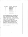
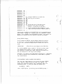
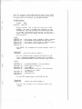
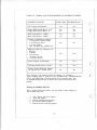
VIASYN
Customization Guide
Concurrent DOS 8-16
CompuPro
CUSTOMIZATION GUIDE
FOR
CONCURRENT DOS 8-16
CONCURRENT DOS 8-16 CUSTOMIZATION GUIDE
Copyright 1985 Viasyn Corporation
Hayward, CA 94545
First Edition: February, 1985
Latest Printing: June, 1985
Part No. 8221-0022
Filename: CDOSCUST.MAN
DISCLAIMER - Viasyn Corporation makes no representations or
warranties with respect to the contents hereof and specifically
disclaims any implied warranties of merchantability or fitness
for any particular purpose. Further, Viasyn reserves the right
to revise this publication and to make any changes from time to
time in the content hereof without obligation of Viasyn to notify
any person of such revision or changes.
Registered trademarks: Televideo, Televideo, Inc. Zenith, Zenith
Radio Corporation, CompuPro, Viasyn Corporation.
Compound trademarks: Concurrent DOS 8-16 is a compound trademark
of Digital Research, Inc. and Viasyn Corporation.
Trademarks:
Digital Research, Digital Research. Qume, Qume
Corporation.
All rights reserved. No part of this publication may be
reproduced or transmitted in any form, or by any means, without
the written permission of Viasyn. Printed and assembled in the
United States of America.
CONCURRENT DOS 8-16 CUSTOMIZATION GUIDE
Copyright 1985 Viasyn Corporation
Hayward, CA 94545
First Edition: February, 1985
Latest Printing: June, 1985
Part No. 8221-0022
Filename: CDOSCUST.MAN
DISCLAIMER - Viasyn Corporation makes no representations or
warranties with respect to the contents hereof and specifically
disclaims any implied warranties of merchantability or fitness
for any particular purpose. Further, Viasyn reserves the right
to revise this publication and to make any changes from time to
time in the content hereof without obligation of Viasyn to notify
any person of such revision or changes.
Registered trademarks: Televideo, Televideo, Inc. Zenith, Zenith
Radio Corporation, CompuPro, Viasyn Corporation.
Compound trademarks: Concurrent DOS 8-16 is a compound trademark
of Digital Research, Inc. and Viasyn Corporation.
Trademarks: Digital Research, Digital Research. Qume, Qume
Corporation.
All rights reserved. No part of this publication may be
reproduced or transmitted in any form, or by any means, without
the written permission of Viasyn. Printed and assembled in the
United States of America.
CONTENTS
Using This Guide
Two Methods for
1
Customization........................................................
1
XIOS Files Supplied with Concurrent DOS 8-16
1-2
Possible Changes Using DDT86
2-3
Possible Changes with Reassembling
3
Customizing the XIOS Using DDT86
Modifying the Device Tables
Saving DDT86 Changes
3-6
6-8
8
Customizing Your Loader Using DDT86
8-10
Customizing Your XIOS by Editing and Reassembling
10
The Source Files
10-11
The GLOBAL.EQU and HEADENTR.A86 Files................................11-12
Editing the GLOBAL.EQU File
12-14
Editing the HEADENTR.A86 File
14-16
Reassembling Your XIOS
16-17
Generating a New System - GENCCPM
18
USING THIS GUIDE
This guide is for those of you who have setup Concurrent DOS 8-16
using one of the XIOS files provided, and now wish to customize
certain parameters. Customizing should only be done if one of
the standard XIOS files does not meet all of the needs of your
system. You may also want to customize parameters in the loader
you have chosen for your system such as the baud rate of the
system console or the step rate of your floppy drives.
Note that customization of printer or terminal related
characteristics may require changes in the TTYS or LPRS files.
Refer to your "Concurrent DOS 8-16 Installation Guide" for
information on making changes to the TTYS or LPRS file.
TWO METHODS FOR CUSTOMIZATION
There are two methods for customizing your operating system.
Which one you use depends on the particular changes you want to
make.
The first method uses DDT86, the Digital Research dynamic
debugging tool. DDT86 allows you to interactively change, or
"patch", already assembled machine language programs. With
Concurrent DOS 8-16 you can use DDT86 to patch the XIOS and the
loader files supplied on the distribution diskettes.
The second method of customization involves editing certain
modules of source code provided by CompuPro on the distribution
diskettes. The edited modules are then assembled using RASM86,
and linked with already assembled code modules supplied by
Digital Research to produce a new XIOS file.
When customizing a XIOS file by DDT86 patch or the RASM86
assembler, you must then use GENCCPM to build that XIOS file into
a useable CCPM.SYS file. Customizing the loader only requires
DDT86 patching.
Both DDT86 and RASM86 are explained in more detail in the
"Programmer's Utility Guide" found in your Digital Research
Concurrent CP/M documentation. GENCCPM is explained in detail in
the "System Guide" from Digital Research.
XIOS FILES SUPPLIED WITH CONCURRENT DOS 8-16
XIOS stands for extended Input/Output System. The XIOS is a code
module that handles the physical interface to Concurrent CP/M and
can be modified to handle a variety of specific needs. CompuPro
supplies an assortment of assembled XIOS files set up for various
different hardware configurations. In addition, CompuPro
supplies the source for certain key parts of the XIOS for
reassembly and customization. (These files are explained in the
section Editing and Reassembling the XIOS.)
Your Concurrent DOS 8-16 Installation Guide from CompuPro lists
the 14 XIOS files offered on your operating system diskettes.
They are repeated here for your convenience.
Generic Terminal Files (end in 'G')
Generic refers to a terminal with no internal pages
of RAM such as a Qume 102.
XIOS305G - DISK 3, ST506 5 Mbyte hard disk
XIOS320G - DISK 3, 20 Mbyte hard disk
XIOS340G - DISK 3, 40 Mbyte hard disk
XIOS380G - DISK 3, 80 Mbyte hard disk
XIOS220G - DISK 2, 20 Mbyte hard disk
XIOS240G - DISK 2, 40 Mbyte hard disk
XIOSFLPG - DISK 1 or DISK 1A, floppy only system
Televideo Terminal Files (end in 'T')
Televideo refers to a terminal with screen switching
capabilities identical to those of the Televideo 925/925 or
Qume 108.
XIOS305T
XIOS320T
XIOS340T
XIOS380T
XIOS220T
XIOS240T
XIOSFLPT
- DISK 3, ST506 5 Mbyte hard disk
- DISK 3, 20 Mbyte hard disk
- DISK 3, 40 Mbyte hard disk
- DISK 3, 80 Mbyte hard disk
- DISK 2, 20 Mbyte hard disk
- DISK 2, 40 Mbyte hard disk
- DISK 1 or DISK 1A, floppy only system
POSSIBLE CHANGES USING DDT86
The parameters of the XIOS of Concurrent DOS 8-16 that may be
changed using DDT86 (Dynamic Debugging Tool) are as follows:
* Number of physical consoles (from 1 to 14).
* Number of virtual consoles per physical console (from 1 to
4),
* Number of list devices (printers, from 0 to 5) .
* Number of auxiliary devices (modems, from 0 to 4).
* Console baud rate and setup parameters (System Support 1).
NOTE: Changing the baud rate of the system console
requires the loader and the XIOS to be changed along with
the TTYS file. Changing the baud rate of any other
terminal requires only the TTYS file to be changed.
* Console, list and auxiliary device physical mapping onto
the interfacer user ports.
* Floppy disk (8" and 5.25") step rates.
NOTE: Changing the step rate of a floppy drive requires
changes to the XIOS and loaders.
* Terminal dependent codes for screen switching.
Patches that can be made to the loaders are changes to the baud
rate of the system console and the step rate of the floppies on
the floppy loaders. Changes to a loader do not require a GENCCPM
be done afterward.
POSSIBLE CHANGES WITH REASSEMBLING
Reassembling the XIOS requires DR ASSEMBLER + TOOLS, an assembler
package available from CompuPro but not included with Concurrent
DOS 8-16.
The parameters of Concurrent DOS 8-16 that may be changed with
reassembly of the XIOS include those changes that can be made
using DDT86 as well as the following:
* Number and type of hard disks supported.
* Number of floppy disks supported.
-Four 8" floppies
-Four 5.25" floppies
-Two 8" and two 5.25" floppies
* terminal drivers.
* DPB's and DPH's for all drives.
CUSTOMIZING THE XIOS USING DDT86
DDT86 allows you to make changes to your XIOS file as well as
changes to your loader. Changes to the XIOS file must be
followed by a GENCCPM in order to generate the new CCPM.SYS file.
First, choose the XIOS file you want to customize. Then, create
a backup by typing:
0A>PIP XIOS.CON=XIOS????.CON[V]
[RET]
where XIOS????.CON is the XIOS file you have chosen to use from
the above list of XIOS files offered as part of Concurrent DOS
8-16.
You are now ready to enter into DDT86. The listings outlined in
this guide are applicable to each of the standard XIOS files
supplied by CompuPro.
A brief description of DDT86 commands will help you understand
exactly what DDT is doing. For a more detailed understanding of
DDT86, refer to the "Programmer's Utilities Guide" from Digital
Research.
D - displays memory in hexadecimal and ASCII
L - lists memory using assembler mnemonics
R - reads a program for subsequent testing
S - substitutes memory values
X - examines and optionally alters the CPU state
W - writes changed file back to disk
The DDT86 prompt for you to enter your commands is '-'. In the
following instructions, the commands listed after the DDT86
prompt '-', indicate the commands you should type in. The
characters to be input at the keyboard by you are underlined.
Enter into DDT86 by typing:
OA>DDT86
[RET]
At the '-' prompt, you may begin your entries as follows:
DDT86 1.2
-rXIOS.CON
START
END
XXXX:YYYY
XXXX:0000
-xcs
CS
0000 zzzz
(ZZZZ=XXXX + 0008, this value should be
DS 0 0 0 0 zzzz
placed in the CS and DS registers to
SS WXYZ
initialize them for the correct segments.)
-s0C10
(Typing "s0C10" starts listing the locations and contents of
values which determine the number of consoles and printers.
It also puts the operator into the substitute mode.
Type a carriage return at a line to leave the contents
there unchanged; type a new value and a carriage return to
replace the value shown. All values are in hex.)
ZZZZ.:0C10 07
ZZZZ:0C11 0E
(This is the number of physical consoles;
values from 01 to OE.)
(This is the total number of virtual consoles.
The value equals virtual consoles per individual
physical console multiplied by the number of
physical consoles; values from 01 to 3C.)
ZZZZ.:0C12 0E
(Total console control blocks; same as virtual
consoles.)
ZZZZ:0C13 02
(This is the number of list devices; values
from 0 to 5. This value indicates how many
significant entries there are in the list
device table starting at address 0C50.)
ZZZZ:0C14 00
A period ends the listing of locations in the substitute mode and
returns you to the DDT86 prompt.
-s0C3A
(Typing "s0C3A" puts you in the substitute mode at the
locations of the 8" and 5" floppy disk step rates.)
ZZZZ:0C3A CF
(8" floppy disk step rate; Values DF=3 ms.,
8F=8 ms.)
ZZZZ:0C3B 46
(a return will enter the default value)
ZZZZ:0C3C DF
(5.25" floppy disk step rate; Values are the
same as 8" disks)
ZZZZ:0C3D
1E
(enter default value)
(The locations of the SYSTEM SUPPORT I initialization bytes
follow.)
ZZZZ:0C3E EE
ZZZZ:0C3F 7E
ZZZZ:0C40 27
(System Support 1, USART mode register 1)
(System Support 1, USART mode register 2,
includes baud rate value)
(System Support 1, USART command register)
(The locations of the I/O CONSOLE TABLE follow.
Instructions on modification of this table are given below.)
ZZZZ:0C41 00
ZZZZ:0C42 08
ZZZZ:0C43 07
ZZZZ:0C44 04
ZZZZ:0C45 03
ZZZZ:0C46 02
ZZZZ:0C47 01
ZZZZ:0C48 0A.
ZZZZ:0C49 0B
ZZZZ:0C4A 0C
ZZZZ:0C4B 0D
ZZZZ:0C4C 0E
ZZZZ:0C4D 0F
ZZZZ:0C4E 10
(Console 0, System Support 1)
(Console 1, Interfacer 3/4, User 7 (8-1=7))
(Console 2, Interfacer 3/4, User 6 (7-1=6))
(Console 3, Interfacer 3/4)
(Console 4, Interfacer 3/4)
(Console 5, Interfacer 3/4)
(Console 6, Interfacer 3/4)
(Console 7, Second Interfacer 3/4, User 09 (0A1=09))
(Console 8, Second Interfacer 3/4, User 10)
(Console 9, Second Interfacer 3/4, User 11)
(Console 10, Second Interfacer 3/4, User 12)
(Console 11, Second Interfacer 3/4, User 13)
(Console 12, Second Interfacer 3/4, User 14)
(Console 13, Second Interfacer 3/4, User 15)
(The locations of the LIST DEVICE TABLE follow.
Instructions on modification of this table are given below.)
ZZZZ:0C4F 05
ZZZZ:0C50 06
ZZZZ:0C51 09
ZZZZ:0C52 00
ZZZZ:0C53 00
(Printer 0, Interfacer 3/4, User 4)
(Printer 1, Interfacer 3/4, User 5)
(Printer 2, Interfacer 3/4, User 8; Note that
this is the third entry of the LIST DEVICE TABLE,
and even though it is set up for USART 09, it
will only be significant at boot time if the
value determining the number of printers
[location 0C13] is three or greater.)
(Printer 3)
(Printer 4)
(The locations of the AUX DEVICE TABLE follow. Instructions
on modifications of this table are given below.)
ZZZZ:0C54 00
ZZZZ:0C55 00
ZZZZ:0C56 00
ZZZZ:0C57 00
ZZZZ:0C58 00
(Aux 0)
(Aux 1)
(Aux 2)
(Aux 3)
(Number of auxiliary devices; Value from 0 to
3)
(Finally, at locations 0C5E to 0C60 are values which relate
to the virtual console characteristics of the terminal
drivers.)
ZZZZ:0C5E 02
ZZZZ:0C5F 01
ZZZZ:0C60 30
(Number of virtual consoles per physical
consoles; Value 1 to 4)
(Above value minus 1)
(Value of the first page of memory in the
terminal; ex: 108, 925, 950, etc.; this value
is FF with a generic 'G' XIOS file or a
Televideo 'T' XIOS file)
Modifying the Device Tables
Each of the three tables shown above are are limited in effect by
a byte value. The I/O CONSOLE TABLE has a total of thirteen
entries, but only as many entries as there are PHYSICAL CONSOLES
(as designated by the constant at location 0C10) will be read in
by the system at boot time. The LIST DEVICE TABLE has a total of
five entries, but only as many entries as there are LIST DEVICES
(as designated by the constant at location 0C13) will be read in
by the system at boot time. The AUX DEVICE TABLE has a total of
four entries, but only as many entries as there are AUX DEVICES
(as designated by the constant at location 0C58) will be read in
at boot time.
Each of the entries in these tables contain hex values
corresponding to USARTs assigned to the that entry's device. The
USART numbers are mapped to the actual physical I/O boards in the
manner illustrated in TABLE # 1.
TABLE #1: MAPPING OF USART NUMBERS TO ACTUAL I/O DEVICES
PCON NUMBER
0
1
2
3
4
5
6
8
9
A
B
C
D
E
I/O BOARD
RELATIVE USER
SYSTEM SUPPORT I
INTERFACER 3/4
INTERFACER 3/4
INTERFACER 3/4
INTERFACER 3/4
INTERFACER 3/4
INTERFACER 3/4
INTERFACER 3/4
2nd INTERFACER 3/4
2nd INTERFACER 3/4
2nd INTERFACER 3/4
2nd INTERFACER 3/4
2nd INTERFACER 3/4
2nd INTERFACER 3/4
7
6
3
2
1
0
9
10
11
12
13
14
15
In the software as supplied by CompuPro the tables are set up for
fourteen consoles and three printers using a SYSTEM SUPPORT I and
two INTERFACER 3s. The number of PHYSICAL CONSOLE DEVICES is set
for seven, and the number of LIST DEVICES is set for two; these
values are the maximum possible for systems with only one
INTERFACER 3 (the average system). So for most systems, to add
another printer, you would either have to add another
INTERFACER 3 OR 4 or rearrange a USART assignment from the I/O
CONSOLE TABLE to the LIST DEVICE TABLE. In either case, you
would have to adjust the device constants accordingly.
For example, if you want to add a third printer on your system,
but you only have one INTERFACER 3, you have to decrease your
total of consoles from seven to six. You could remove console 6
by replacing the 01 (USART 01) at location 0C47 with the 0A from
location 0C48 below it, and moving each entry in the table up one
(0B where 0A was, 0C where 0B was, etc.) until you get to the
last CONSOLE DEVICE entry (0C4E) which would be set to 00. Then
you could reassign that USART 01 to the third entry in the LIST
DEVICE TABLE (0C51). Finally you would decrease the PHYSICAL
CONSOLES constant (0C10) from 07 to 06, and increase the LIST
DEVICES constant (0C13) from 02 to 03. If you changed the table
in this way it would look like this:
ZZZZ:0C44
ZZZZ:0C45
ZZZZ:0C46
ZZZZ:0C47
ZZZZ:0C48
ZZZZ:0C49
ZZZZ:0C4A
ZZZZ:0C4B
ZZZZ:0C4C
ZZZZ:0C4D
ZZZZ:0C4E
ZZZZ:0C4F
ZZZZ:0C50
ZZZZ:0C51
00
08
07
04
03
02
01
0A
0B
0C
0D
0E
0F
10
05
06
09
ZZZZ:0C52
00
ZZZZ:0C41
ZZZZ:0C42
ZZZZ:0C43
—
—
—
—
—
—
0A
0B
0C
0D
0E
0F
10
00
--01
(reassign USART 0A as console 06)
(move up rest of entries)
(set the last entry of the table to 00)
(Printer 0, first entry in list table)
(Printer 1, second entry in list table)
(replace USART 09 with USART 01 in third
entry of the LIST DEVICE TABLE, printer 2)
Changing the assignment of AUX DEVICES can be accomplished in the
same manner: reassign the USARTs in the I/O CONSOLE TABLE,
assign a free USART to the AUX DEVICE TABLE, and change the
PHYSICAL CONSOLE and AUX DEVICE constants accordingly.
Saving DDT86 Changes
To save changes in DDT86, end the address listing with a period.
At the next '-', type the command 'W' followed by the file name
on the same line and all changes made in DDT86 will then be
saved.
-WXIOS.CON
(This will save your changes to the XIOS file)
To exit from DDT86, press a control C. Be sure you have saved
your changes before exiting. It is also a good practice to save
your XIOS file to another drive under a different file name to be
sure you always have a safe copy of your changes.
Remember, any changes to the XIOS must be followed by a GENCCPM
in order to generate a new CCPM.SYS file. GENCCPM is explained
later in this manual.
CUSTOMIZING YOUR LOADER USING DDT86
You may also make changes to your loader file using DDT86.
First, load the loader file you are using into DDT86. The
loader files offered are listed in your "Concurrent DOS 8-16
Installation Guide". To read your loader into DDT86, type:
0A>DDT86
[RET]
After a quick sign-on, you will be given the DDT86 prompt '-'.
Type 'R' to read in a file followed by the name of your loader
file. For example, to work on the loader file for a system using
8" floppies with a CPU 8085/88, type "RLDRCCPM8.88":
-RLDRCCPM8.88
START
END
8400:0000 8400:1F7F
(Listing locations 153F to 1542 will reveal two 16-bit
pointers, one used to compute the locations for the
initialization bytes for the console I/O and the other used
to compute the locations for the step rate for the boot
floppy. The pointers may change, but they will always be at
these locations.)
-S153F
8400:153F A9
8400:1540 19
8400:1541 88
8400:1542 1A
8400:1543 81
-- (This pointer, 19A9, is added to
-- the location of the console I/O
-- (This pointer, 1A88, is added to
-- the location of the floppy step
369H to compute
init. bytes.)
300H to compute
rate.)
(The DDT86 "H" command can be used to add the offset of
369H.)
-H19A9,369
1D12 1641
(1D12 is the effective address.)
(Use the substitute mode to display the console I/O init.
bytes. A thorough explanation of these bytes is available
in the SYSTEM SUPPORT I technical manual. Type "s1D12".)
-S1D12
8400:1D12 5E
8400:1D13 5A
8400:1D14 5E
8400:1D15 7E
8400:1D16 5F
8400:1D17 27
8400:1D18 57
(SYSTEM SUPPORT 1 I/O port address.)
(mode register 1 init. byte)
(port address)
(mode register 2 init. byte; 7E for baud rate
of 9600, 7F for 19.2K)
(port address)
(command byte)
(Use the "H" command again to add 1A88 and 300)
-H1A88,300
1D88 1788
(1D88 is the effective address.)
(List the step rate byte in the substitute mode; type
"slD88".)
-sD188
8400:1D88 CF -- (Step rate byte for boot floppy, either 8" or
5.25". In this byte, the first nibble
determines the step rate. A value of FF is
for a step rate of 1 ms., EF for 2 ms., DF for
3 ms., CF for 4 ms. and so on to OF for 16 ms.)
8400:1D89 .
(This concludes the loader changes you can make using DDT86.
Any changes can be saved by typing "w" followed by the name
of the file to which you wish to save the results. To save
the changes in file "LDRNEW.88" type "wLDRNEW.88":)
-wLDRNEW.88
This completes the changes you may make to the parameters of the
XIOS file and LOADER.CMD file using DDT86.
CUSTOMIZING YOUR XIOS BY EDITING AND REASSEMBLING
You can customize much of the characteristics of the Concurrent
DOS 8-16 operating system by editing source code, assembling it,
linking it with other assembled code modules, and building it
into a CCPM.SYS file using the GENCCPM program.
This section explains what source code is supplied with
Concurrent DOS 8-16, how to edit it, and how to reassemble and
link it. All of the following changes require reassembling your
XIOS with DR Assembler + Tools, an assembler package not included
with Concurrent DOS 8-16 but available from CompuPro.
The Source Files
Four source files are supplied with the Concurrent DOS 8-16
distribution diskettes: HEADENTR.A86, GLOBAL.EQU, DPBS.EQU, and
DPBS.A86. Two other files are included by assembler directives
in the assembly of HEADENTR.A86 and must be present on the
working disk when the assembly process begins. These files are
SYSTEM.LIB and SYSDAT.LIB. A brief definition of each of these
files follows:
HEADENTR.A86 - This file contains the Concurrent CP/M
XIOS entry points and header block,
terminal specific codes, floppy disk
specify bytes, and character I/O device
mapping tables.
SYSTEM.LIB
General system equates that have been
defined by Digital Research and are
not subject to change.
SYSDAT.LIB
Digital Research defined equates not
subject to change.
GLOBAL.EQU
General system configuration equates
that may be changed to accomodate
changes involving hard disks,
terminals, etc.
DPBS.EQU
General equates applied to DPB's (Disk
Parameter Block) and DPH's (Disk
Parameter Header) generation. Instructions
on modifying this file are not available
from CompuPro.
DPBS.A86
DPB and DPH data. Instructions on modifying
this file are not available from CompuPro.
Note that while the files DPBS.EQU and DPBS.A86 are included on
the distribution diskettes, CompuPro does not support
modifications to them through this document or any other. They
are included so that experienced systems level assembly language
programmers may undertake to modify the characteristics of the
logical drives which CompuPro supports (e.g. logical drive size)
or even to support drives available from sources other than
CompuPro. Documentation on the data structures involved in these
files can be found in the Digital Research Concurrent CP/M-86
System Guide included with Concurrent DOS 8-16.
The files explained here are HEADENTR.A86 and GLOBAL.EQU.
The GLOBAL.EQU and HEADENTR.A86 Files
Both the GLOBAL.EQU file and the HEADENTR.A86 file contain many
specific values you may want to change to better adapt your
operating system to your needs.
Table #2 illustrates the changes that can be made to
the HEADENTR.A86 and GLOBAL.EQU files.
TABLE #2: GLOBAL.EQU AND HEADENTR.A86 POSSIBLE CHANGES
POSSIBLE CHANGES
GLOBAL.EQU HEADENTR.A86
5.25" Floppy Disk Equates
Yes
No
Floppy Disk Specify Bytes - 5.25"
Floppy Disk Specify Bytes - 8"
No
No
Yes
Yes
Hard Disk Equates - DISK 2
Hard Disk Equates - DISK 3
Yes
Yes
No
No
Console Configuration Equates*
-# of physical consoles (Pcon)
-# of Vcons per Pcon
-# of list devices
-type of console (e.g. QUME 102)
Yes
No
Mapping Tables for Character I/O
Devices*
-Consoles
-List devices
-Auxiliary devices
-# of Aux devices
No
Yes
System Support Initialization
No
Yes
Terminal Specific Driver Tables
No
Yes
Yes
No
Console Screen Buffering Equates
(as required for a Zenith Z-19)
*Any changes to the console, list device (printer), or auxiliary
device mapping must be reflected in the GLOBAL.EQU, HEADENTR.A86,
TTYS, and LPRS files. Console and list device mapping may also
be patched through DDT86 as shown in the previous section of this
manual.
Editing the GLOBAL.EQU File
There are five basic areas where you may need to make changes to
the GLOBAL.EQU file:
1.
2.
3.
4.
5.
5.25" floppy disk drive equates
Hard disk equates
Console configuration equates
PC Graphics Board equates
Console screen buffering equates
Here are explanations of all of the pertinent equates in the order
in which they appear.
FLOPPY5
- Set True if you have 5.25" drives; False if you do not
have 5.25" drives.
HEADS5
- Set to the number of heads of your 5.25" drives.
to 2 for CompuPro 5.25" drives.
TRK5
- Set to the number of tracks of your 5.25" floppy. Set
to 80 for CompuPro 5.25" drives.
Set
FLPYORDR - Set to 0 if physical drive 0 should be the "A8"
drive in a floppy only system. Set to 2 if physical
drive 2 should be the "A8" drive in a floppy only
system, i.e. 5.25" drives. (Only values 0 and 2 are
valid. Has no effect on hard disks systems.)
DISK2
- Set to true if a DISK 2 is present. (Set to false if a
Disk3 is present.)
DISK3
- Set to true if a DISK 3 is present. (Set to false if a
DISK 2 is present.)
D2M20
- Set to true when using 20 Mbyte Fujitsu HD.
D2F40b
- Set to true when using 40 Mbyte Fujitsu HD.
D3ST506
- Set to true when using 5 Mbyte ST506 HD.
D3Q520
- Set to true when using a 20 Mbyte Quantum HD.
D3Q540
- Set to true when using a 40 Mbyte Quantum HD.
D3Q80
- Set to true when using an 80 Mbyte Quantum HD.
NPCONS
- Number of physical consoles.
VCOFF
- Number of virtual consoles per physical console.
NLST
- Number of list devices.
Z19
- Set to true if terminal type is Zenith Z-19. Only one
terminal can be set to true. The Zenith Z-19 is a
terminal without RAM paging capability for which
Digital Research has included drivers which emulate the
RAM paging in main memory. These drivers consist
mostly of equates which correspond to the terminal's
control codes. CompuPro includes them with the
distribution diskettes as an example for those who wish
to support screen switching on other terminals which do
not have RAM paging capability. CompuPro will not
assist in supporting terminals other than those mentioned
in this document.
TELEVIDEO- Set to true if terminal type is Televideo 925 or
Qume QVT-108.
QUME102
- Set to true if terminal type is Qume QVT-102. The QVT102 is also a terminal without RAM paging capability.
CompuPro has not implemented buffered console screen
switching for this terminal, but it has implemented
code which does a clear screen and homes the cursor
after a screen switch.
PCBRD
- Indicates presence of PC Graphics Board. Set to false
unless PC Graphics Board documentation indicates
otherwise.
CONBUFF - This is a value indicating how much memory to allot for
a console screen buffer. It is only significant if the
Z-19 equate is true or if you are developing console
buffering for a terminal other than those supported by
ComnpuPro.
Any equates in GLOBAL.EQU that are not explained above are not
intended for change by CompuPro at this time.
Editing the HEADENTR.A86 File
There are four basic areas which you might need to change in the
HEADENTR.A86 file:
1.
2.
3.
4.
Floppy disk specify bytes
SYSTEM SUPPORT I I/O port reinitialization string
I/O character device mapping tables
Terminal definition tables
These areas are explained below:
1.
The floppy disk specify bytes are equates which determine
the step rate for both 5.25" and 8" floppy disks. Here are
explanations of the equates:
SRT8 -
8" floppy drive step rate. Set to "16 - 4" by VIASYN
for a step rate of 4 ms. The number subtracted from 16
is equal to the resultant step rate.
SRT5 -
5" floppy drive step rate. Set to "16 - 3" by CompuPro
for a step rate of 3 ms. Same formula as for SRT8.
2.
The SYSTEM SUPPORT I is first initialized by the loader and
then reinitialization by the XIOS. The bytes for the second
initialization are represented in binary form on the fourth page
of the HEADENTR.A86 file. The programming comments in the code
explain clearly the functions of the bytes. For information on
how the bytes can be changed, consult the SYSTEM SUPPORT I
Technical Manual.
3. There are three character device tables: CONTABLE for I/O
consoles, LSTABLE for list devices, and AUXTBL for auxiliary
devices. They are shown below:
NOTE: System Support 1 should always be the first console.
CONTABLE
DB
0,8,7,4,3,2,1,10,11,12,13,14,15,16
LSTABLE
DB 5,6,9,0,0
AUXTBL
DB
0,0,0,0
AUXNUM
DB
0
The numbers in these tables are USART numbers as explained in
TABLE #1 in this manual.
In CONTABLE, there are fourteen entries corresponding to
consoles 0 to 13 counting from left to right. This assumes that
there are two INTERFACER 3s in the system.
In LSTABLE, there are five entries corresponding to printers 0 to
4. The third entry in LSTABLE assumes that there are two
INTERFACER 3's in the system. The last two entries in LSTABLE
are zero meaning no USART is assigned to them.
In AUXTBL there are four entries corresponding to auxiliary
devices 0 to 3. All entries in AUXTBL are zero meaning no USARTs
are assigned for auxiliary devices.
All of these tables are limited by a constant elsewhere in the
code. If the constant for number of physical consoles (NPCONS in
the GLOBAL.EQU file) is set to 07, then only the first seven
entries in CONTABLE are read in at boot time. The remaining
entries are insignificant. LSTABLE is limited by NLST in the
GLOBAL.EQU file, and AUXTBL is limited by AUXNUM here in the
HEADENTR.A86 file.
To reassign USARTs in these tables to support a different
combination of character devices:
A. Remove the appropriate USART number from one table.
B. Move the remaining entries in the table over to the left
to fill in the gap left by the removal in step 1.
C. Enter a zero at the now empty last entry on the table.
D. Enter the USART number into the first free entry, or in
place of an entry that is not significant, in the table
for the devices you wish to increase.
E. Make sure that the values NPCONS, NLST, and AUXNUM are
all updated to reflect the new table configuration.
For example, if we want to remove console 6 and add printer 3 in
its place, and if our system has only one INTERFACER 3, the new
table would look like this:
CONTABLE
DB
0,8,7,4,3,2,10,11,12,13,14,15,16,0
LSTABLE
DB
5,6,1,0,0
AUXTBL
DB
0,0,0,0
4. There are three terminal definition tables in the
HEADENTR.A86 file: one for Televideo 925 or Qume QVT-108
terminals, one for QUME QVT-102 terminals, and one for Zenith Z19 terminals. These tables contain constants related to terminal
control characters that are used when a screen switch is
requested by the user. They are supplied by CompuPro as examples
to assist programmers developing drivers for terminals other
than those which CompuPro supports. No further support for other
terminals is available from CompuPro.
The remaining constants in HEADENTR.A86 are defined by CompuPro
and should not be changed.
Reassembling Your XIOS
STEP 1. To assemble the new HEADENTR.A86 file with the new
GLOBAL.EQU equates, type:
0A>RASM86 HEADENTR
$PZSZLO
[RET]
$PZSZLO - The CompuPro recommended parameters for
reassembly. (Consult your Digital
Research documentation for details.)
This produces the file HEADENTR.OBJ
STEP 2. Pick the hard disk file appropriate to your system and
rename it HDISK.OBJ by typing:
0A>PIP
HDISK.OBJ=HDISK?.OBJ[VROW]
where HDISK?.OBJ = HDISK240.OBJ
= HDISK220.OBJ
= HDISK3.OBJ
= HDISKNHD.OBJ
-
[RET]
for DISK 2, 40 Mbytes
for DISK 2, 20 Mbytes
for DISK 3, any size
for systems with no
hard disk
HDISK.OBJ is a file containing the assembled but not
linked hard disk support code.
STEP 3. Pick the appropriate file for the PC Video board by
typing:
0A>PIP
VSCPG.OBJ=VSC???.OBJ[VROW]
[RET]
where VSC???.OBJ is VSCNPC.OBJ - for a system without a
PC Video board; and VSC???.OBJ is VSCYPC.OBJ - for a
system with a PC Video board.
VSCPC.OBJ is the file containing the assembled but not
linked PC Video card code.
STEP 4. Pick the appropriate serial terminal driver file by
typing:
0A>PIP VSCREEN.OBJ=VSC???.OBJ[VROW] [RET]
where VSC???.OBJ is VSCREENG.OBJ - for most types of
terminals; and VSC???.OBJ is VSCZ19.OBJ - for Zenith Z19
terminals.
VSCREEN.OBJ is the file containing the assembled but not
linked terminal dependent screen drivers.
STEP 5. The object files you've just created and others must now
be linked together. The necessary files are:
HEADENTR.OBJ
INITENT.OBJ
INTVEC.OBJ
PIC.OBJ
CTC.OBJ
TICK.OBJ
NP8087.OBJ
CONOUT.OBJ
SEROUT.OBJ
VSCREEN.OBJ
CONIN.OBJ
SERIN.OBJ
SSINT.OBJ
I3INT.OBJ
SERVAR.OBJ
LIST.OBJ
SWITCH.OBJ
STATLIN.OBJ
VCCB.OBJ
SERDATA.OBJ
FUNC56.OBJ
VSCPC.OBJ
DENTRY.OBJ
RESKEW.OBJ
MDISK.OBJ
FD.OBJ
PCMODE.OBJ
CPROXIOS.INP
HDISK
PCKEY
To link all the object files together, type:
0A>LINK86 CPROXIOS[I]
[RET]
NOTE: Depending on the version of LINK86, you may get
undefined symbols dealing with the 8087. This is because
some versions of LINK86 do not support 8087 references.
These will have no effect on the final result.
STEP 6. The resulting command file, CPROXIOS.CMD, must be renamed
by typing:
0A>REN XIOS.CON=CPROXIOS.CMD
[RET]
This completes the changes you may make to your XIOS. After
making any changes to your XIOS, you must run a GENCCPM in order
to generate a new system that incoroporates these changes.
GENERATING A NEW SYSTEM - GENCCPM
In order to build a CCPM.SYS file we will need to run the GENCCPM
program. The necessary files are:
SUP.CON
MEM.CON
PIN.RSP
VOUT.RSP
STATLINE.RSP*
SYSDAT.CON
XIOS.CON
CIO.CON
BDOS.CON
RTM.CON
SHELL.RSP or SHELL.NPC (only one)**
ABORT.RSP
* STATLINE.RSP replaces CLOCK.RSP in the Digital Research
documentation.
** SHELL.RSP includes the PC module; SHELL.NPC does not include
the PC module.
You may also want to include DIR.RSP. This will allow you to run
DIR without loading it from the disk. However, do not include
DIR.RSP in systems that will use the network. DIR.RSP does not
operate properly on the network.
Your Concurrent DOS 8-16 diskettes include an input file called
COMPUPRO.IN to be used when doing a GENCCPM. The input file
allows you to input the system generation commands for a GENCCPM.
In the programmer's section of your Digital Research
documentation, the System Guide gives an explanation of GENCCPM
input files. Review this section to familiarize yourself with
input files.
To run the GENCCPM program with the input file, type:
0A>GENCCPM <COMPUPRO.IN
[RET]
The screen will rapidly scroll several pages of output and then
stop with a MENU. At this point, type:
GENSYS
The GENCCPM program will complete the building of a new CCPM.SYS
file.
After running a GENCCPM, reassembly of the XIOS is completed.
You now have a custom CCPM.SYS file and your customization is
complete.