1
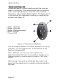
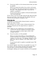
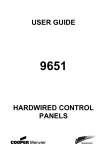
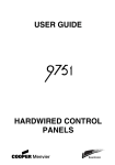
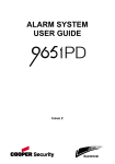
Homelink 75
Security System
Administrator’s Guide
Contents
Introduction ........................................................ 3
Controls and Displays ..........................................5
The Display ....................................................6
Keys:.............................................................7
Administration..................................................... 8
Entering the User Menu .......................................8
Voice Memo .......................................................9
Recording a Voice Memo...................................9
Deleting a Voice Memo .....................................9
Omit Zones ...................................................... 10
Users .............................................................. 11
Adding Users ................................................ 11
Editing Existing Users..................................... 16
Deleting Users .............................................. 17
View Log ......................................................... 17
Facilities On/Off ................................................ 18
Test ................................................................ 19
System Configuration ........................................ 21
Set Date and Time......................................... 21
Outputs........................................................ 21
Re-Programming Telecommands for Users ........ 23
Starting a Call To Downloader ......................... 24
Summer/Winter Time..................................... 25
Message Volume ........................................... 26
Installer Access ............................................. 26
About Comms ............................................... 27
Follow Me ........................................................ 27
Outputs ........................................................... 28
Telephone Call.................................................. 28
List of Menu Options.......................................... 30
Page 2
Introduction
The Homelink75 is a wireless intruder alarm system that
provides several features specially for domestic use.
These include social alarm monitoring (including remote
listen-in capabilities), inactivity alarm monitoring, direct
communication to mobile telephones and voice
messaging.
The heart of the Homelink75 system is the 7510r control
unit. The control unit has:
A graphic display and keypad from which you can
operate the system.
A high output siren for alarms.
A speaker for operating tones, voice prompts and
speech messages.
A power supply, including stand-by batteries.
Signalling equipment supporting all major alarm
reporting formats, including speech messaging.
A proximity tag reader.
Speech recording and playback facilities.
A microphone for remote listen-in.
The control unit can operate a range of wireless
peripherals; Figure 1 shows some examples. (Not shown
in Figure 1 are the special receiver units required to
provide wireless outputs. These will be fitted by the
installer to operate the equipment you specify.)
In addition to wireless peripherals the control unit also
provides sets of connectors for two hardwired detectors
and two relay outputs. If necessary the installer can use
these connectors to link the control unit to older wired
detectors or siren/strobe units.
Page 3
Introduction
1. Single button pendant panic
alarm.
2. Single button wrist/pendant
panic alarm.
3. Two button panic alarm.
4. Two button panic alarm with
tiltswitch.
5. Four button telecommand.
6. Door Contact/Universal
Transmitter.
7. Smoke Detector.
8. Passive Infra Red.
9. External siren/strobe.
Figure 1. Homelink75 Peripherals
A complete Homelink75 system comprises a control unit
and up to:
32 wireless alarm zones
32 wireless outputs
one external siren/strobe unit
16 four button telecommands
16 panic alarm buttons
50 users.
This rest of this guide shows the simple procedures
required to operate the control unit, and administer the
system. For information on installing the 7510r control
unit please read 7510r Installation Guide. Each of the
radio peripherals also have their own guides.
Page 4
Introduction
Controls and Displays
Figure 2 shows the controls and displays available on the
control unit.
1
2
3
4
5
6
7
8
9
0
#
8
1. LCD display .
2. Set key.
3. Navigation and “soft” keys.
4. Numeric keypad.
5. Unset key.
6. Emergency keys.
7. Social care alarm key.
8. Microphone.
Figure 2. Controls and Displays
Page 5
Introduction
The Display
The display shows messages and prompts to help guide
you through setting, unsetting and programming the
system.
When the system is idle
(either while set or
unset) the display shows
the “standby screen”,
comprising the time and
date:
01:12
01/01/2004
Menu
The word “Menu” on the bottom left indicates that if you
press the left hand soft key then you can gain access to
the User Menu (see page 8).
To draw your attention to special events the standby
screen may also display the following icons:
A voice memo is waiting (see page 9).
The social care activity monitor is working
(see page 18).
The control unit has some information for
you to look at.
A partition is set.
A partition is unset.
A partition is part set.
Page 6
Introduction
Keys:
Full sets the system.
Unsets the system.
u
Scroll up.
n
Scroll down.
(no markings) The function of these keys
depends on the guiding text shown on the
bottom line of the display above the keys.
In the instructions on the following pages a
name shown in capitals, for example SELECT or
DONE, means the key under that word in the
bottom line of the display.
1 to 0,
*, #
Used when keying in user codes and telephone
numbers.
#
When keying in text for names press # to
change between capitals or small letters. The
top right corner of the display shows “ABC” for
capitals and “abc” for small letters.
Press to start a social care alarm.
To operate the following keys press both at the same
time:
v
To start a Fire alarm.
To start a PA alarm.
M
To start a Medical alarm.
Page 7
Administration
To make changes to the way your system works you
must enter the User Menu. Your degree of access to the
User Menu depends on what type of user you are:
Administrator or Normal User. An Administrator has
access to all the options of the User Menu. A Normal
User:
Can change their own access code.
Cannot add or delete other users.
Cannot use the System Config option.
Entering the User Menu
1.
Make sure the display shows the standby screen.
2.
Press MENU.
3.
Key in an Administrator access code.
The display shows the first item in a list of options.
The slider bar on the right of the screen indicates
how far down the list you are. (See page 30 for a
complete list of options.)
4.
Press u or n to scroll through the list of options
available, followed by SELECT to gain access to an
option.
5.
Press EXIT to leave an option when you have
finished making changes.
6.
Press EXIT again to leave User Menu.
The rest of this chapter describes each of the main
options in the User Menu.
Page 8
Administration
Voice Memo
You can leave a short voice message on the system. Any
user can play back the message, either when they unset
the system or by entering User Menu – Voice Memo –
Play Message. The standby screen shows a small icon
) to indicate that a message is waiting (see page 8).
(
Recording a Voice Memo
1.
Enter the User Menu and select Voice Memo.
The display shows a short menu: (you will see
“Record Message” by itself if there is no message
already recorded).
2.
Select Record Message and start speaking.
As you talk a progress bar shows how much time
you have left.
Press DONE to finish recording.
3.
Select Play Message to hear the message.
Press u or n to increase or decrease the volume.)
Press CANCEL to stop playing the message.
At the end of the message the display shows
“Playback Complete”.
4.
EITHER press RESTART to play the message again.
OR press DONE to return to the Voice Memo menu.
Deleting a Voice Memo
Select User Menu – Voice Memo – Delete Message to
delete a stored voice memo.
Page 9
Administration
Omit Zones
You may wish to prevent a zone causing an alarm. For
example, if you have a fire door that is normally closed
and protected by a detector you may wish to leave it
open for fresh air or to move goods in and out. To do this
the control unit allows you to "Omit" a zone.
The control unit allows you to omit a zone for one
setting/unsetting cycle. You will have to omit the zone
again for the next setting/unsetting cycle.
1.
Enter the User Menu and select Omit Zones.
The display shows the first of a list of zones.
2.
Press u or n to highlight the zone you wish to
omit.
3.
Press CHANGE to mark the zone for omission.
The character at the end of the line changes to an
"O" to show that the zone will be omitted.
If you change your mind then press CHANGE until
the end of the line shows an "I".
4.
Repeat steps 2 and 3 for any other zone you wish
to omit (or include).
5.
Press DONE to store the changes you have made.
Page 10
Administration
Users
The control unit can recognise up to 50 individual users.
Select Users in the User Menu to add new users, change
their details, or delete them from the system.
Adding Users
Note: When adding a new user you can also assign them
to partitions, and allocate them proximity tags,
telecommands, pendants and panic alarm transmitters.
The instructions to do this extend to page 16.
To add a new user:
1.
Enter the User Menu and select Users.
The display shows the options for the Users menu.
2.
Select Add User.
The display shows the current name given to the
user, and places a cursor at the end of the name.
3.
Press DELETE to remove letters to the left of the
cursor. (See Note.) Key in the new name from the
keypad. Press each key one or more times to obtain
the letter you want (see Figure 3, the letters of the
alphabet appear on the keys in the same
arrangement as on many mobile phones.)
u moves the cursor left, n moves the cursor to the
right.
Press # to change between capitals and small
letters.
4.
Press OK when finished.
Note: If you keep pressing DELETE until the whole name
is gone, and then press DELETE once more the
control unit assumes you do not wish to add a new
user.
Page 11
Administration
ABCÆÅÄ
DEF
GHI
JKL
MNOØÖ
PQRS
TUV
WXYZ
Space'():.-!&
Figure 3. Letters Assigned to Keys
User Types
When you complete the user name, the display shows
which user types are available. The highlighted line
shows which type is currently assigned to the user.
6.
Highlight the user type you wish to give the user
and press SELECT.
See page 8 for a brief explanation of Administrator and
Normal User.
Partitions
Once you have selected the user type, the display shows
a list of partitions that you can assign to the user.
YES at the end of the line means that the user can set
and unset that partition.
(In your system the installer may have given each
partition its own name.)
7.
Press u or n to highlight a partition and then press
CHANGE to assign the user to or remove them from
the partition.
8.
Press OK when you have assigned the user to all
the partitions they need.
Page 12
Administration
Access Code
After assigning users to one or more partitions, the
display requests you to assign an access code to the
user.
9.
Key in an access code for the user.
When you press the last digit of the access code the
display asks you to key in the same access code
again. Make sure that you key in the same digits in
the same order.
Proximity Tags
A proximity tag is a small plastic token with a low
powered radio transmitter inside. Each tag contains a
unique identity code. Inside the control unit, at the top
left corner of the case, is a sensor. When you present the
tag within about 10mm of the front of the case, at the
top left corner, the control unit senses the presence of
the tag and reads its identity code.
If a user presents a tag that the control unit recognises
then the control unit allows the user to access the system
in the same way as if they had keyed in a recognised
access code.
When you have finished giving the new user an access
code, the control unit then gives you the opportunity of
registering an proximity tag for the same user.
10.
Present a tag to the top left corner of the case.
The control unit learns the identity of the tag, and
the display asks you to register a telecommand
(see below).
You cannot register more than one tag per user. If
you present a tag that the control unit has already
registered to another user then you will hear a
single low tone and the display will remain asking
you to present the tag.
If you do not wish to register a tag for the user
then press "NO TAG"
Page 13
Administration
Telecommands
A telecommand is a small remote control that you can
attach to a keyring. The telecommand has four buttons
and a small light that glows when the telecommand
transmits a signal. When delivered from the factory three
of the buttons are dedicated to setting or unsetting the
system (see Figure 4).
1. Button 1 (Full Set).
2. Button 2 (Part Set).
3. Button 3 (Not programmed).
4. Button 4 (Unset).
5. Transmit LED.
Figure 4. Telecommand Buttons.
You can program Button 3 to switch outputs on or off. (If
you wish, you can program any of the buttons to any
function, see page 23.)
When adding a new user you may register one
telecommand to that user. If you wish to register more
telecommands to a user employ the Users - Edit User
option.
After asking if you wish to add a tag, the control unit
gives you the opportunity to register a telecommand for
the user.
Page 14
Administration
11.
Press any button on the telecommand that you wish
to register.
.
When you press the button the control unit learns
the identity of the telecommand and registers it to
the user. (The display then asks if you wish to
register a pendant.)
If you do not wish to register a telecommand press
"NO TELECOMMAND".
If the control unit has already learned that telecommand
then you will hear a low tone and the display tells you
that the telecommand is already in use.
Pendants
A pendant is a single button telecommand, used as a
social care alarm button.
After asking if you wish to learn a telecommand, the
control unit gives you the opportunity to register a
pendant.
Note: While you are registering a new pendant the
control unit will not respond to an alarm signal
from any pendant or panic alarm (PA) it has
already learned.
12.
Press the button on the pendant.
When you press the button on the pendant the
control unit learns the identity of the pendant and
registers it to the user. The display changes to ask
you if you wish to register a PA (Panic Alarm, see
below).
If you do not wish to register a pendant press "NO
PENDANT".
You cannot register more than one pendant to a user. If
the control unit has already learned that pendant then
you will hear a low tone and the display remains
unchanged, asking you to press a button on the pendant.
Page 15
Administration
PA (Panic Alarms)
A PA is a two button telecommand, used to start a Panic
Alarm. To activate the transmitter you must press both
buttons at the same time. A third button acts as a lock so
that you can prevent the PA going off when carrying it in
your pocket.
After asking if you wish to learn a pendant, the control
unit gives you the opportunity to register a PA.
Note: While you are registering a new PA the control unit
will not respond to an alarm signal from any
pendant or PA it has already learned.
13.
Squeeze both buttons on the PA.
When you squeeze the buttons the control unit
learns the identity of the PA and registers it to the
user.
If you do not wish to register a pendant press "NO
PA".
You cannot register more than one PA per user. If the
control unit has already learned that PA then you will
hear a low tone and the display remains unchanged,
asking you to press the buttons on the PA.
Editing Existing Users
If you wish to change the details for an existing user
then:
1.
Enter the User Menu and select Users - Edit User
The display shows a list of the users already
programmed into the control unit, one user per
screenfull.
2.
Press u or n to display the user you wish to edit,
and then press Select.
The display shows a list of the options that you can
edit. Use the u or n keys to see more options.
Page 16
Administration
3.
Select the option you wish to edit.
The options available are the same as those shown
when adding a user.
4.
Press DONE when you have finished.
Note that you can delete tags, telecommands, pendants
and PAs from each user. If you wish to reprogram the
function of telecommand buttons see page 23.
Deleting Users
To remove a user from the system:
1.
Enter the User Menu and select Users - Delete User.
The display shows a list of the users.
2.
Press u or n until the display highlights the user
you want to delete.
3.
Press DELETE and then OK.
Once you delete a user, the system does not respond to
their access code or to their proximity tag. In addition,
the control unit "forgets" the identity of all telecommands
and pendants and PAs registered to the user.
View Log
The control unit keeps a log of the last 250 events (for
example, alarms and setting/unsetting). You can read
the log when the system is completely unset.
1.
Enter the MENU and select View Log.
The display shows you the most recent log event.
2.
Press u or n to scroll through the log.
n shows earlier events.
u shows more recent events.
3.
Press EXPANDED to see details of the time and
date.
4.
Press Back when you have finished reading the Log.
Page 17
Administration
Facilities On/Off
You can switch the following facilities on or off:
When you
switch on:
The control unit:
Chime
Gives a tone whenever something
triggers a zone programmed with the
Chime attribute.
Voice Prompts
Uses a pre-recorded voice message to
announce the setting and unsetting
stages of the system
Activity
Monitor
Monitors zones that the installer has
programmed as Activity Monitor zones.
If nothing triggers these zones for a
specified number of hours then the
control unit raises an alarm. While
Activity Monitoring is on the display
icon in the top right
shows a small
corner.
To switch these one of these facilities on or off:
1.
Enter the User Menu and select Facilities On/Off.
2.
Select the facility you want to switch on or off.
3.
Press CHANGE until the word ON or OFF appears at
the end of the line.
4.
Press DONE.
Page 18
Administration
Test
If you think that part of the system is not working
correctly then you can use the Test option to test various
peripherals. If the test confirms that part of the system is
not working then contact your installer.
The Test option also lets you check the identity of
Telecommands, Pendants and Tags.
To start testing, make sure the system is idle then:
1.
Enter the User Menu and select Test.
The display shows the Test menu.
2.
Select the part of the system that you wish to test.
You can test each part listed in the Test menu as follows:
Siren
Press On/Off to turn the siren on and off
again. The word "On" or "Off" at the top
right of the display shows whether you
should be hearing the siren.
Loudspeaker
Press On/Off to play a test message from
the loudspeaker. The word "Playing"
appears at the top right of the display
when you should be hearing the message.
Keypad
Press each key once. The display shows a
character in response. Press both dual
keys together to test. Press OK to end the
test.)
Walk test
The display shows a list of all the
detectors installed on the system. Walk
round and trigger each detector. Every
time you trigger a detector the control
unit gives a double tone and the display
shows an "A" at the end of the line for
that detector. Note that you cannot test
24 hour or fire zones.
Page 19
Administration
Outputs
The display shows a list of the outputs
installed on the system. Select the output
you wish to test. Press DONE to finish the
test.
NOTE: Make sure no one tries to activate
the radio output module using a
telecommand or pendant when you
perform the test.
When you complete the test check that
the output is still in the state you wish it
to be in.
Telecommands
Press any button on the telecommand.
The display shows the identity and user of
the telecommand, and the button that the
control unit believes you pressed. Press all
the buttons on the telecommand in turn.
Pendants
Press the button on the pendant. The
display shows the identity and user
assigned to the pendant.
Panic Alarms
Press both buttons on the panic alarm
transmitter. The display shows the identity
of the user assigned to the panic alarm.
Tag
Present the tag to the top left hand corner
of the front of the control unit. The display
shows the user assigned to the tag.
Page 20
Administration
System Configuration
The System Configuration option allows you to set up
parts of the system to suit your particular needs. If you
need more extensive changes to the operation of the
system then you can select Menu - Call to Downloader to
connect your control unit to an installer's PC. Downloader
software on the PC provides more extensive
programming facilities.
Make sure the system is idle.
1.
Enter the User Menu and select System Config.
The display shows the System Configuration menu.
2.
Select the item you wish to configure.
Set Date and Time
When setting the date use u or n to adjust the day
number. Press NEXT to highlight the month. Again, use
u or n to adjust the month number. Press NEXT to
select the year and use u or n to adjust the year
number. Press NEXT to move on to setting the time.
When setting the time use u or n to adjust the hours.
Press NEXT to highlight the minutes and use u or n to
adjust the minutes. Press OK to store the new setting.
Outputs
The 7510r can control several radio output modules,
each of them capable of switching an attached electrical
device on or off on command.
The control unit operates a radio output module by
broadcasting a message every time it wants the module
to react. Each message contains the identity of the
control unit, a channel number, and an instruction to
either "Activate", "Deactivate" or "Toggle". Every radio
output module in range hears the broadcast. To make
sure that only selected modules respond the installer
makes them learn the identity of the control unit, and
which channel number they are supposed to respond to.
Page 21
Administration
During programming the installer may allocate some
outputs so that they can be reprogrammed by an
Administrator. The following section describes how the
Administrator can use those outputs.
Programming an Output Channel
If you wish to program an output that an installer has
allocated for use by an Administrator:
1.
In the User Menu select System Config - Outputs Edit Output.
The display shows the Edit Output menu, with a list
of the outputs.
2.
Select the output Channel you wish to edit
The display shows a menu that allows you to
change the name of the selected output, and to set
an “On” and “Off” time for the output.
3.
Select Name to give the output a meaningful name.
The keypad allows you to enter letters as shown in
Figure 3.
The name you give the output appears in all the
other menus the display offers for controlling
outputs.
4.
Select “On Time” to set a time when the control
unit will switch the output on. Select “Off Time” to
set a time when the control unit will switch the
output off. If you do not wish the output to switch
on and off at set time then leave these two options
set to “00:00”.
Note: You can switch the output on and off from the User
Menu by selecting Outputs On/Off (see page 28).
If you want to program a telecommand to control
the output, see page 23.
Page 22
Administration
Re-Programming Telecommands for
Users
The System Config - Telecommands option allows you to
re-program buttons on a telecommand.
1.
Enter the User Menu and select System Config Telecommands - Edit.
2.
Press the button you want to reprogram on the
telecommand.
Note: If you do not have the telecommand press "NO
TELECOMMAND".
The display presents a list of the registered
telecommands and their users. Select the
telecommand you want to edit. Press u or n to
select the button you wish to re-program.
Once you have selected the button you wish to reprogram the display gives you the option of reprogramming the button to either set/unset some
part of the system, or to operate one of the
outputs. Select the option you wish to use from the
display.
Deleting Telecommands
If a user has lost a telecommand you should delete it
from the system to make sure that no unauthorised
person can use it to gain access. Also, if you wish to
reassign a device to another user, you must first delete it
from the system.
1.
Enter the User Menu and select System Config.
2.
Select Telecommand – Delete.
The display shows a message asking you to identify
the telecommand you wish to delete.
2.
Press a button on the device that you wish to
delete.
Page 23
Administration
Note: If you do not have the device press "NO
TELECOMMAND".
The display shows a list of the registered devices.
Select the device you wish to delete.
The display shows the details of the device you
have selected.
3.
Press YES to confirm that you wish to delete the
device.
The control unit will let you delete all telecommands in
one operation. Think carefully before you use this
feature.
1.
Enter the User Menu and select System Config Telecommand - Delete All.
the display asks you for confirmation.
2.
Press Yes.
The control unit "forgets" all telecommands that
were registered to it.
To register telecommands with users once again enter
the User Menu and select Users - Edit User.
Starting a Call To Downloader
Your Installer may be using a personal computer to
program your alarm system remotely. The software the
Installer uses for this purpose is called <Downloader>.
There may be times when your Installer asks you to
make your alarm system start a call out to the Installer's
<Downloader>. Your alarm system is programmed to call
one of two different telephone numbers or one of two
different Internet numbers. You do not have to know
these numbers, your Installer has programmed them for
you, and will tell you which one to select.
Page 24
Administration
To start the call:
1.
Enter the User Menu and select System Config Call Downloader.
The display shows the Call to Downloader menu.
2.
Select Telephone Number 1 or 2, or IP Address 1 or
2 as instructed by your installer.
The control unit calls the installer's computer on the
number you selected.
Your system may be connected to Downloader for
several minutes.
When Downloader has finished and the connection
is broken the display shows the time and date.
Summer/Winter Time
The 7510r can alter its internal clock to allow for the
change over to or from daylight saving time in spring and
autumn. However, if you live in a region where the
change over does not take place at the customary time
(last weekend of March or last weekend of October) then
you can change the time yourself.
1.
Enter the User Menu and select System Config –
Summer/Winter Time.
The display shows the Summer/Winter Time menu.
2.
Either: Select “Automatic” to allow the 7510r to
change between Summer and Winter time on its
own.
Or: Select “Manual” to change the time at a date of
your own choosing.
If you select manual you must change to Summer or
Winter time using System Config – Set Time menu.
Page 25
Administration
Message Volume
If you have voice prompts switched on (see page 18),
then you may wish to adjust their volume.
1.
Enter the User Menu and select System Config –
Message Volume.
The display shows “Message Volume – Set Volume”
2.
Press u to make voice prompts lounder, or n to
make them quieter. Every time you press one of
those keys the 7510r plays a beep to demonstrate
its new volume.
3.
Press Done to accept the volume you have
selected.
Installer Access
You may wish to ensure that an installer or maintainer
cannot gain access to program your system unless a user
is present. To do this:
1.
Enter the User Menu and select System Config –
Installer Access.
The display shows “User code to prog” with either
the letter Y or N at the end of the line.
2.
Press CHANGE to change Y to N or N to Y.
A “Y” means that after the installer/maintainer
enters their access code, the system asks for a user
access code before allowing access to the Installer
Menu.
A “N” means that the installer/maintainer can enter
the Installer Menu by simply keying in their own
code.
3.
Press Done to confirm your choice.
Page 26
Administration
About Comms
If you wish to check what type of telecommunication line
your control unit has, enter the User Menu and select
System Config – About Comms.
The display shows “PSTN” if your control unit is
connected to a land line, “GSM” if you have a GSM
module, or “ISDN” if your control unit is connected to an
ISDN line.
If your 7510r has a GSM module fitted, the screen
displays the IMEI number, the signal strength, network
provider and GSM telephone number. (Note that some
mobile phone service providers withhold the GSM number
from the display.)
Follow Me
Your alarm system can be programmed to call one or
more telephone numbers to report alarms. However, you
may intend to stay at another address and would like
alarm calls diverted to a telephone at that address. The
control unit allows you to enter one telephone number
that it will use temporarily for reporting alarms.
1.
Enter the User Menu and select Follow Me.
The display shows the current "Follow Me"
telephone number.
2.
Key in the new "Follow Me" telephone number and
press OK.
Page 27
Administration
Outputs
You can operate radio output modules from the keypad,
as well as by using a telecommand. To operate an
output:
1.
Enter the User Menu and select Outputs.
The display shows a list of outputs.
2.
Use the u or n keys to select the output you want
to operate and then press CHANGE.
The selected output shows the word ON or OFF at
the end of its line
3.
Press DONE.
The display returns to the list of outputs, and the
control unit sends a signal to the radio output
module to operate the appropriate output.
Telephone Call
If your 7510r is connected to a telecommunications line,
then you can start and end a telephone call from the
keypad. However, depending on the type of line
connected to your 7510r, you may not have complete
two way speech. If you are connected to:
PSTN
You can dial out and listen to the remote end,
and also send DTMF tones from the 7510r
keypad. You can use this service for choosing
options from an automated answering service,
or to control equipment at the far end of the
line.
ISDN
You can dial out and have a complete two way
speech with a person at the far end. You can
also send DTMF tones from the keypad.
GSM
You can dial out and listen to the remote end,
and also send DTMF tones from the 7510r
keypad. This type of line should work with an
automated answering service, such as those
Page 28
Administration
used by many mobile phone providers to
register SIM cards and check their credit level.
If you attempt two way speech then a person
at the far end of the line may find it difficult to
hear you well.
To start a telephone call:
1.
Enter the User Menu and select Telephone Call.
2.
Key in the telephone number you wish to dial and
then press OK.
The control unit makes the telephone call. When
the called party answers you will be able to hear
them. If the called party is operating an automatic
answering service, you can press the number keys
on the control unit keypad to generate tones to
control the answering service.
Page 29
Administration
List of Menu Options
Item
Voice Memo
Play
Record
Delete
Omit Zones
(Zone 01, 02, …)
Users
Edit User
(for each user:)
Name
Type
Partitions
Code
Tag
Telecommands
Pendants
PA
Add User
Delete User
View Log
Facilities On/Off
Chime
Voice prompts
Activity monitor
Test
Siren
Loudspeaker
Keypad
Walk test
Outputs
Telecommands
Pendants
Panic Alarms
Tags
Page 30
Page
9
9
9
9
10
8
16
11
12
12
11
13
14
14
16
11
17
17
18
18
18
18
19
19
19
19
19
20
20
20
20
20
Administration
Item (cont’d)
System Config
Set Date & Time
Ouputs
Telecommands
Call Downloader
Summer/Winter Time
Message Volume
Installer Access
About Comms
Follow Me
Follow Me Number
Outputs
Output 01, 02, …
Telephone Call
Number to Dial
Page
21
21
21
23
24
25
26
26
27
27
28
28
Page 31
© Cooper Security Ltd. 2006
Every effort has been made to ensure that the contents of this book are
correct. However, neither the authors nor Cooper Security Limited
accept any liability for loss or damage caused or alleged to be caused
directly or indirectly by this book. The contents of this book are subject
to change without notice.
Printed and published in the U.K
Part Number 11673833 Issue 1
Page 32