1
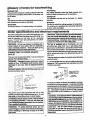
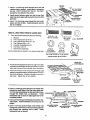
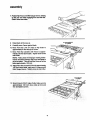
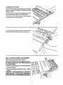
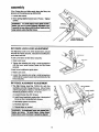
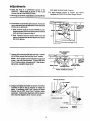
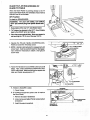
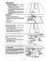
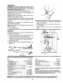
Save This Uanuam For
Future Reference
MODEL NO'S,
113o298722
113.298762
SAW WITH LEGS
TWO CAST IRON
TABLE EXTENSIONS
MOTOR AND
QUICK RELEASE
RiP FENCE
Serial
Number
Modelandserialnumbermaybefound
at the left-handside ofthe base.
SEAFW / CRRFTSMRH
You should record both model and
serial number in a sale place for future
use.
IO.INCH TABLE SAW
FOR YOUR
SAFETY:
• assembly
ooperating
° repair parts
Read ALL
INSTRUCTIONS
CAREFULLY.
_,,
Sold by SEARS,
Part No. SP5627
ROEBUCK
illll
AND CO., Chicago,
IL. 60684 U.S.A.
Printed in U.S.A.
FULLONEYEARWARRANTY
ONCRAFTSMAN
TABLESAW
If wlth|noneyearfromthedaleof purchase,
this Craftsman
TableSawfallsdueto
a defect in
mstedal or wo_manshlp, Sears will repair it, free of charge. This warranty applies only while this
product is in use in the United States.
WARRANTY SERVICE IS AVAILABLE BYSIMPLY CONTACTING THE NEAREST SEARS SERVICE
CENTER/DEPARTMENT THROUGHOUT THE UNITED STATES.
THIS WARRANTY APPLIES ONLY WHILE THiS PRODUCT iS USED IH THE UNITED STATES.
This warranty gives you specific legal rights, and you mayalso have other rights which vary from
state to state.
SEARS, ROEBUCK AND CO., D/817 WA Hoffman Estales, IL 60195
v
.....
safety instructions for table saw
Safety is a combination of common sense, staying alert
and knowing how your table saw works. Read this
manual to understand this saw.
BEFORE USING THE SAW
serious,
Injury,
do not
the saw In
until the permanent
following steps
have
beenplug
satisfactorily
completed.
Guard, Spreader, Anti-Kickbackdevice, Miter Gauge,
Fence, Table Insert and Blade Elevation and Bevel
Controls. (See page 25)
4. Review of the maintenance methods for this saw.
(See page 43)
Read the DANGER label found on the front of the saw,
2. To avoid injury from unexpected saw movement:
A. Put the saw on a firm level surface where there is
4. GROUND THE SAW- This saw has an approved 3conductor cord and a 3-prong grounding type plug.
The plug fits grounding type outlets desig ned for 120
volt 15 amp circuits. The green conductor in the cord
isthegrounding wire. To avoid electrocution, NEVER
connect the green wire to a live terminal.
5. To avoid injuryfrom electrical shock, make sure your
fingers do not touch the plug's metal prongs when
plugging in or unplugging the saw.
6. To avoid back injury, get help or use recommended
casters when you need to move the saw. Always get
help if you need to lift the saw. Hold the saw close to
your body. Bend your knees so you can lift with your
legs, not your back.
7. NEVER STAND ON TOOL. Serious injury could
occur ifthe tool tips or you accidentally hit the cutting
tool. Do not store anything above or near the tool
where anyone might stand on the tool to reach them.
BEFORE EACH USE:
anything.
B. Check for alignment of moving parts, binding of
moving parts, breakage of parts, mounting, and
i
•
_ua
r_j
_
goggles that meet
ANSI 2:871 standa_s.
E 3. _notDo
trot macfi around Or over saw
II:_
.
p
gL,_rd down and i_ 7. When rtppixtg. use push stick when
place f_r through cut_
fence ,Is set 2 _nches or more from
5. Do not do freehamd cuts.
bla6_.
6. Keep hands out of path of saw 8. Know how to reduce the risk af
9. When
riPPing,
auxiliaw
between
blade.
Do
use
push
blOCk
and
fence wherl fence
_s set
V2 and 2 irt_hes from
not nlake
rip cuts
narrower than _/2 inch
10. Turn
_0owex
to stop
off and
before
walt
adjusting
fo_ blade
or
|
__
E. REMOVE ADJUSTING KEYS AND WRENCHES.
Form habit of checking for and removing keys and
adjusting wrencheslrem tool before turning it on.
F. To avoid injury from jams, slips or thrown pieces
(kickback and throwback):
1. USE ONLY
"RECOMMENDED
ACCESSO-
RIES" (See page 43). Follow the instructions
that come with the accessories. Using other accessories may be dangerous.
2. Choose the right blade or cutting accessory for
the material and the type of cutting you plan to
do.
3. Never use grinding wheels, abrasive cut-off
wheels, friction wheels (metal slitting blades)
wire wheels or buffing wheel. They can fly apart
explosively.
4. Choose and inspect your cutting tool carefully.
a. To avoid cutting toolfailure and thrown shrapnel (broken pieces of blade), use only 10" or
smaller blades or other cutting tools marked
for speeds of 3450 rpm or higher.
B. Dress for safety:
1. Do not wear loose clothing, gloves, neckties or
jewelry (dngs, wristwatches). They can get
caught and draw you into moving parts.
2. Wear nonslip footwear.
3. Tie back long hair.
4. Roll long sleeves above the elbow.
5. Noise levels vary widely. To avoid possible
hearing damage, wear ear plugs or muffs when
using saw for long periods of time.
6. Any power saw. can throw foreign objects into
the eyes.
This can cause permanent eye
damage. Wear safety goggles (not glasses)
that comply with ANSI Z87.1 (shown on package). Everyday eyeglasses have only impact
resistant lenses. They are not safety glasses.
Safety goggles are available at Sears retail
catalog stores. Glasses or goggles not in compliance with ANSI Z87.1 could seriously hurt
you when they break.
WEAR
YOUR
b. Always use unbroken, balanced blades
designed to fit this saw's 5/8 inch arbor.
c. When thru-sawing (making cuts where the
blade comes through the workpiece top),
always use a 10 inch diameter blade. This
keeps the spreader in closest to the blade.
d. Do not overtighten arbor nut.
wrenches to "snug" it securely.
Use arbor
e. Use only sharpbladeswith properly set teeth.
Consult a professional blade sharpenerwhen
in doubt.
f. Keep blades clean of gum and resin.
5. Adjust table inserts flush with the table top.
NEVER use the saw without the proper insert.
6. Make sure all clamps and locks are tight and no
parts have any excessive play.
2. Keep work area clean
A. Cluttered areas and benches invite accidents.
Floor must not be slippery from wax or sawdust.
B. To avoid burns or other fire damage, never use the
saw near flammable liquids, vapors or gases.
C. To avoid injury, don't do layout, assembly, or setup
work on the table while the blade is spinning. It
could cut or throw anything hitting the blade.
Plan ahead to protect your eyes, hands,face, ears.
AVOID ACCIDENTAL STARTING - Make sure
switch is "OFF" before plugging saw in.
3. Plan your work
A. USE THE RIGHT TOOL - Don't force toot or
attachmentto do a job it was not designed for.
7. For dusty operations, wear a dust mask along
with the safety goggles.
C. Inspect your workpiece. Make sure there are no
nails or foreign objects in the part of the workplece
to be cut.
D. Plan your cut to avoid KICKBACKS and THROWBACKS - when a part or all of the workpiece binds
on the blade and is thrown violently back toward
the front of the saw.
1. Never cut FREEHAND:
Always use either a
Rip Fence, Miter Gauge or fixture to position
and guide the work, so itwon't twist, bind on the
blade and kickback.
2. Make sure there's no debris between 1ne workpiece and its supports.
3. When cutting Irregularly shaped workpieces,
plan your work so it will not slip and pinch the
blade:
a. A piece of molding, for example, must lie flat
or be held by a fixture or jig that wiU not let it
twist, rock or slip while being cut. Use jigs or
fixtures where needed to prevent workpiece
shifting.
b. Use a different, better suited type of toot for
work that can't be made stable.
or vibrates a lot, stop immediately. Turn the saw off.
Unplug the saw. Do not restart until finding and fixing
the problem.
4. Use extra caution with large,, very small or
awkwardworkpisces.
a. Use extra supports(tables, sawhorses,block,
etc.) for any workpieces large enough to tip
when not hell down to thetable top. NEVER
uSe another person as a substitute for a
table extension, or as additional support for a
workpiece that is longer or wider than the
basic saw table, orto help feed, support or
pull the workpisce.
2. Make sure the top of the arbor or cutting tool turns
toward the front of the saw.
3. Set the cutting tool as low as possible for the cut
you're planning.
4. KEEP CHILDREN AWAY. All visitors should be kept
a safe distance from work. Make sure bystanders are
clear of the saw and workplece.
b. Never confine the piece being cut off, that is,
the piece NOT againstthe fence, mitergauge
or fixture. Never hold it, clamp it, touch it, or
use length stops against it. It must be free to
move. Ifconfined, itcould getwedged against
the blade and cause a kickback or throwback.
5. Let the blade reach full speed before cutting.
6. DON'T FORCE TOOL. It will do the job better and
safer at its designed rate. Feed the workpiece intothe
blade only fast enough to let it cut without bogging
down or binding.
7. Before treeing any jammed material
A. Turn switch "OFF".
c. Never cut morethan one workpiece at a time.
B. Unplug the saw.
d. Never turn your table saw"ON" before clearing everything except the workpiece and
related support devices off the table.
4, Planthawayyouwill
C. Wait for all moving pars to stop.
D. Check blade, Spreader and Fence for proper alignment before starting, again.
pushtheworkplecethrough
8. To avoid throwback of cut off pieces;
A. NEVER pull the workpleo_ through. Start and
finish the cut from the front of the table saw.
A. Use the Guard assembly.
B. NEVER put your fingers or hands in the path of
the sawblade or other cutting tool.
B. To remove loose pieces beneath or trapped inside
the guard:
1. Turn saw "OFF".
C. N EVER reach In back ofthe cuttingtoolwith either
hand to hold down or support the workpiece,
remove wood scraps, or for any other reason.
2. Remove switch key.
3. Wait for blade to stop before liftingthe Guard.
D. Avoid hand positions where a sudden slip could
cause fingers or hand to move into a sawblade or
other cutting tool.
E. DON'T" OVERREACH.
and balance.
ADDITIONAL
FOR
RIPTYPE CUTS
Always keep good footing
1. NEVER use the Miter Gauge when ripping.
2. Use a Push Stick whenever the fence is 2 or more
inches from the blade. When thru-sawing, use an
Auxiliary Fence and Push Blockwhenever the Fence
mustbebetween 1/2 and 2 inchesof the blade. Never
thru-saw rip cuts narrower than 1/2 inch. (See =BASIC SAW OPERATION - USING THE RIP FENCE"
section.)
F. Push the workpisce against the rotation of the
blade. NEVER feed material into the cutting tool
from the rear of the saw.
G. Always push the workpiece all the way past the
sawblade.
H. As much as possible,keep your face and body to
one skJeof the sawblade, outof line with a possible
kickback or throwback.
3. Never rip anything shorter than 10" long.
4. When using a Push Stick or Push Block, the trailing
end of the beard must be square. A Push Stick or
Blockagainst an uneven end could slip off or push the
work away from the Fence.
5. A FEATHERBOARD can help guide the workpiece.
See "BASIC SAW OPERATION - USING THE RIP
FENCE." Always use Featherboards for any non
thru rip type cuts.
I. NEVERtum the saw =ON" before cieadng the table
of all tools, wood scraps, etc., except the workpiece and related feed or support devices for the
cutp nned.
J. AVOID ACCIDENTAL STARTING - Make sure
switch is =OFF" before plugging saw in.
WHENEVER
INSTRUCTIONS
SAW BLADE iS SPINNING
J +++o+,
WARNING: Don't let familiarity (gained from fie- I
tion of a second Is enough to cause a Severe
Injury.
5/16" APART
4-1/2' +-
1. Before actually cutting with the saw, watcl_ it while it
runsfor a short while, if it makes an unfamiliar noise
4
5"
BEFORE STARTING
1. To avoid kickbacks and slips into the blade, make
sure the Rip Fence is parallel to the sawblade.
2. Check the anti-kickback pawls. (See "BASIC SAW
OPERATION - USING THE RIP FENCE.")
The
Pawls must stop a kickback once it has started.
Replace or sharpen Anti-Kickback Pawls when points
become dull.
3. Plastic and composition (like hardboard) materials
may be cut on your saw. However, since these are
usually quite hard and slippery, the Anti-Kickback
Pawls may not stop a kickback. Therefore, be especially careful in your set-up and cutting procedures.
WHILE CUTTING
1. To avoid kickbacks and slips into the blade, always
pushforward on the section of the workpiece between
the saw blade and the Rip Fence. Neverpushforward
on the piece being cut off.
ADDITIONAL
CROSSCUT
iNSTRUCTiONS
FOR
TYPE CUTS
BEFORE STARTING
1. NEVER use the Rip Fence when crosscutting.
2. An auxiliary wood facing attached to the Miter Gauge
can help prevent workpiece twisting and throwbacks.
Attach it to the holes provided. Make the facing long
enough and big enough to support your worK. Make
sure, however, it will not interfere with the Sawblade
Guard. (See page 26)
3. Use jigs or fixtures to help hold any piece too small to
extend across the full length of the Miter Gauge face
during the cut. This lets you properly hold the Miter
Gauge and workpiece and helps keep your hands
away from the blade.
WHILE CUTTING
1. To avoid blade contact, always hold the Miter Gauge
as shown in the "BASIC SAW OPERATIONS - USING THE MITER GAUGE."
BEFORE LEAVING THE SAW
1. Turn the saw off.
.
Wait for blade to stop spinning.
3. Make workshop child-proof. Lock the shop. Disconnect master switches. Remove the yellow Switch
Key. Store it away from children and others not
qualified to use the tool.
4. Unplug the saw.
glossary of terms for woodworking
Anti-Kickback Pawls (AKP)
Device which, when properly maintained, is designed to
stop the workpiece from being kicked back at the operator during ripping operation.
Arbor
The shaft on which a cutting tool is mounted.
Crosscut
A cutting or shaping operation made across the width of
the workpiece.
Dado
A non through cut which produces a square sided notch
or trough in the workpiece.
Featherboard
A device which can help guide workpieces during rip
type operation.
Freehand
KIckback
An uncontrolled grabbing and throwing of the workpiece
back toward the front of the saw.
Leading End
The end of the workpiece which, during a rip type
operation, is pushed into the cutting tool first.
Molding
A non through cutwhich produces a special shape in the
workpiece used for joining or decoration.
Push Stick
A device used to feed the workpiece through the saw
during narrow ripping type operations and helps keep
the operator's hands well away from the blade.
Push Block
A device used for ripping type operations too narrow to
allow use of a Push Stick.
Performing a cut without using a Fence, Miter Gauge,
fixture, hold down or other proper device to keep the
workpiece from twisting during the cut.
Rabbet
A notch in the edge of a workpiece.
Gum
A sticky, sap base substance that has hardened.
A sticky, sap based residue from wood products.
Heel
Misalignment of the blade.
Kerr
The amount of material removed by the blade in a
throughcut or the slot produced by the blade in a non
through or partial cut.
Resin
Ripping
A cutting operation along the length of the workpiece,
Revolutions Per Minute (RPM)
The number of turns completed by a spinning object in
one minute.
glossary of terms for woodworking
Sawbisde Path
The area ofthe workpiece or table top directly in line with
the part of the workpiece whichwill be, or has been, cut
by the blade.
Set
Thedistance that thetip of the sawblade tooth isbent (or
set) outward from the face of the blade.
Throw-Back
Throwing of pieces in a manner similar to a kickback.
Thru-Sawing
Any cutting operation where the blade extends completely through the thickness of the workpiece.
Trailing End
The workplace end last cut by the blade in a ripping
operation.
Workploce
The item on which the cutting operation is being done.
The surfaces of a workplece are commonly referred to
as faces, ends and edges.
ii
motor specifications
and eiectrica! requirements
Thissawisdesignadtouse a3450RPM motoronly. Do
not use any motor that runs faster than 3450 RPM. It is
wired for operation on 120 volts, 60 Hz., alternating
current. IT MUST NOT BE CONVERTED TO OPERATE ON 230 VOLTS.
WARNING: Failure to properly ground this power
tool can cause electrocution or serious shock,
partlcuisrly when used In damp locations, or near
meta! plumbing. If shocked, your reaction could
cause your hands to hit the cutting tool.
WARNING: Do not use blower or washing
chine motors or any motor with an automatic
reset overload protector. They can start up by
themselves and you could get Injured.
This saw is equipped with a 3-conductor cord and
grounding type plug which has a grounding prong,
approved by Underwriters' Laboratories and the Canadian StandardsAssociation. The ground conductor has
a green lugand is attached to the tool housing at one end
and to the ground prong in the attachment plug at the
other end.
CONNECTING
OUTLET
TO POWER
SOURCE
This saw must be grounded while in use to protect the
operator from electrical shock.
shock or fires.
If the power cord is worn, cut or
damaged In any way, have It replaced immedF
JWARNING:
Damaged power cords can cause
stely.
This plug requires a mating 3-conductor grounding type
outlet as shown.
It is recommended that you have a qualified electrician
replace the TWO prong outlet with a properly grounded
THREE prong outlet.
GROUNDING
Your saw is wired for 120 volts and has a plug that looks
like the one shown below.
/
J
3-PRONG
_'_
LUG
_- J"_,' !I MAKESURETHISIS
_ _,_.-._--
CONNECTED
TO
A
ADAPTER
\
/fl
g/
GROUNDING
PROPERLY
3-PRONG
PRONG
GROUNDED
OUTLET
Plug power cord of fully assembled saw into a 120V
properly grounded type outlet protected by a 15 amp.
time delay or Circuit-Saver fuse or circuit breaker.
your outlet Is properly g rounded, have It checked
by a qualified electrician.
WARNING:
To avoid electrical ShOCk, do not
permit fingers to touch the terminals of the plug,
when Installing or removing the plug to or from
the outlet.
Atemporary adapter, as shown, isavailable forconnecting plugs to 2-prong receptacles. The green grounding
lug extending from the adapter must be connected to a
permanent ground such as to a properly grounded outlet
box. This adapter should be used only until a properly
grounded outlet can be installed by a qualified electrician.
WARNING:
Avold electric shock, lftheoutlet
you
are planning to use for this saw is of the two prong
type, DO NOT REMOVE OR ALTER THE GROUNDING PRONG IN ANY MANNER. Use an adapter, as
shown, and always connect the grounding lug to
a known ground, such as to a properly grounded
outlet box. Not all outlet boxes are properly
grounded, ff you are not sure the outlet box Is
properly grounded, have It checked by a qua llfled
eisctrlclan.
NOTE: The adapterillustratedis for use only if you
already have a properly grounded 2-prong receptacle.
The use of any extension cord will cause some loss of
power. To keep this to a minimum and to prevent
overheating and motor burn-out, use the followingtable
to determine the minimum wire size (A.W.G.) extension
cord.
Use only 3 wire extension cords which have 3-prong
grounding type plugs and 3-prong receptacles which
accept the plug on the saw.
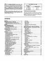
1 H.P. MOTR 110- 120V
Extension Cord
Length
Wire Size A.W.G.
0 - 25 Feet
26 -50 Feet
51 - 100 Feet
No. 16
No. 14
No. 12
CHECK
MOTOR
ROTATION
The motor must rotate CLOCKWISE when viewed from
the shaft end to which you will mount the pulley. (See
page 21 .) If it does not, do not assemble or use saw until
motor with right rotation is installed.
contents
Warranty ....................................................................
2
Safety instructions for Table Saw .......................... 2
Additional Instructions for Rip Type Cuts ............... 4
Additional Instructions for Cross Cut Type Cuts .... 5
Glossary ....................................................................
5
Motor Specifications and
Electrical Requirements ...................................... 6
Connecting to Power Source Outlet ...................... 6
Motor Rotation .......................................................
7
Unpacking and Checking Contents ........................ 8
Tools Needed .........................................................
8
List of Loose Parts .................................................
8
Assembly ................................................................
10
Installing Handwheels .......................................... 10
Checking Table Insert .......................................... 10
Checking Blade Squareness to Table ................. 10
Assembling Steel Legs ........................................ 11
Mounting Saw ......................................................
11
Attaching and Assembling Table Extensions ....... 12
Mounting Switch ..................................................
13
Installing Right Front Rip Fence Guide Bar ......... 14
Installing Rear Fence Guide Bar .......................... 15
Aligning Rip Fence ...............................................
17
Self Aligning Spring Adjustment .......................... 17
Rip Fence Lock Lever Adjustment ....................... 18
Rip Fence Alignment Adjustment ........................ 18
Adjusting Rip Scale Pointer ................................. 19
Installing Blade Guard ......................................... 19
Mounting the Motor ..............................................
21
Installing Belt .......................................................
22
Installing Belt Guard Support ............................... 23
Installing Belt Guard ............................................. 24
Plugging in Motor .................................................
24
Getting to Know Your Saw .................................... 25
On-Off Switch .......................................................
25
Elevation Handwheel ........................................... 26
Tilt Handwheel ....................................................
26
Tilt Lock Handle ...................................................
26
Rip Fence ............................................................
26
Miter Gauge .........................................................
26
Blade Guard .........................................................
26
Table Insert ..........................................................
26
Removing and Installing Sawblade ...................... 27
Exact-I-Cut ...........................................................
27
Safety Instructions for Basic Saw Operation ...... 28
Basic Saw Operation - Using the Miter Gauge ....30
Work Helpers .......................................................
30
Crosscutting .........................................................
31
Repetitive Cutting ................................................
32
Miter Cutting .........................................................
32
Bevel Crosscutting ............................................... 33
Compound Miter Cutting ...................................... 33
Using the Rip Fence ............................................... 33
Ripping .................................................................
34
Bevel Ripping .......................................................
34
Using Featherboards for Thru-Sawing ................. 36
Resawing .............................................................
36
Cutting Panels .....................................................
37
Rabbeting ............................................................
37
Ploughing and Molding ........................................ 37
Dadoing ................................................................
38
Molding Cutting ....................................................
38
Using Featherboards for Non Thru-Sawing ......... 38
Adjustments ...........................................................
39
Miter Gauge .........................................................
39
Heeling Adjustment or Parallelism of Sawblade
to Miter Gauge Groove ................................... 39
Blade Tilt, or Squareness of Blade to Table ........ 41
Tilt Mechanism .....................................................
42
Maintenance ...........................................................
43
Lubrication....: .........................................................
43
Recommended Accessories ................................. 43
Trouble Shooting ...................................................
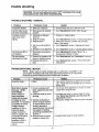
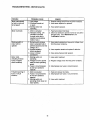
44
General ................................................................
44
Motor ....................................................................
44
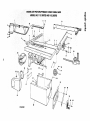
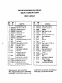
Repair Parts ............................................................
46
unpacking and checking contents
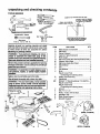
TOOLS
NEEDED
Phillips
Screwdriver
COMBINATION
SQUARE
MUST
BE
TRUE,
STRAIGHT
EDGE
OF BOARD
3, 4" THICK.
THIS
EOGE
MUST
BE PERFECTLY
STRAIGHT.
Medium
Scra_dr|ver
Small
Screwdriver
DRAW
LIGHT
BOARD
ALONG
LINE
THIS
ON
EDGE
_
; '_ _
/
Plier
Combination
SIZE
Square
Set
7/16
Screw
3/32
1/8
5/32
Wrenchea
in, 1/2 in. 91"16 In.
L_
Wrenches
In.
In.
In.
/
SHOULD
BE NO GAP OR OVERLAP
HERE WHEN
SQUARE
IS FLIPPEO
OVER
IN OOTTED
POSITION.
r
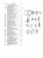
Separate all parts from packing materials and check
each one with the illustration and the list of Loose Parts
tO make certain all items are accounted for, before
discarding any packing material.
ITEM
PART NAME
A
B
C
D
E
H
M
Q
R
S
T
U
tempt to assemble the table saw, plug in the
power cord or turn the switch on until the missing
I WARNING: ff any parts are missing, do not atparts are obtained and are in_alle,(:l correctly.
Remove the protective oil that is applied to the table top
and edges of the table. Use any ordinary householdtype
grease and spot remover.
i
use gasoline, naptha, or similar highly volatile
WARNING:
To avoid fire or health hazard, never ]
solvents.
Apply a coat of automobile wax to the table.
Blade Guard and Spreader ........................... 1
Rip Fence ...................................................... 1
Owner's Manual ............................................ 1
Cast Iron Table Extensions ........................... 2
Miter Gauge .................................................. 1
Rip Fence Guide Bar with Rip Scale (Front]. 1
Support, Motor Base ..................................... 1
Rip Fence Guide Bar (Rear) ......................... 1
Side Stiffener ................................................. 2
Leg ................................................................
4
End Stiffener ................................................. 2
Motor .............................................................
1
Bag of Loose Parts
(Containing the following items)
Outlet, On/Off with Key ................................ 1
Handwheel .................................................... 2
Bracket, "L" Mounting (Model 113.298721) ... 1
Bag of Loose Parts ........................................ 3
Bag of Loose Parts
(Containing the following items)
Wrench ..........................................................
1
Belt, "V" 1/2 x 41 ........................................... 1
Pulley, 112dia. with 5/8 Bore ......................... 1
Spreader, Rod ............................................... 1
Blade Guard Support .................................... 1
Spreader Support .......................................... 1
G
J
AM
Wipe all parts thoroughly with a clean, dry cloth,
!
plug to power source outlet until all assembly
stepsarecomplete,
aad
yousafety,
have mad
and
under- !
WARNING:
For your
own
never
con_
stand the safety and operating Instructions.
QTY.
F
K
L
N
O
P
il/
14
..........
£@
(MODEL 11_L29B762)
H
J
u
(MODEL
8
113.298722 i
ITEM
V
W
X
Y
Z
X
AA
AA
AA
AA
AA
AA
AB
AB
AC
AC
AC
AD
AE ..
AF
AL
AA
AB
AB
AB
AC
AC
AF
AG
AH
AA
AB
AC
AF
AJ
AK
PARTNAME
QTY
BagofLoosePartsNo.
(Containing
thefollowingitems)
BeltandPulleyGuard......................................
1
BeltGuardClip"S". ......................................... 3
Screw, Pan Hd. 10-32 × 1/2 ............................. 2
Support, Belt Guard ......................................... 1
Belt Guard Support Bracket ............................. 1
Bag of Loose Parts .......................................... 2
Bag of Loose Parts
(Containing the following items)
Screw, Pan Hd. 10-32 × 3/4 ............................. 2
Screw, Hex Hd. 1/4-20 × 5/8 ............................ 2
Screw, Hex Hd. 5/16-18 x 5/8 .......................... 3
Screw, Hex Hd. 5/16-18 x 1 ............................. 5
Screw, Hex Hd. 5/16-18 x 1 ............................. 4
Screw, Hex Hd. 5/16-I8 x 1-1/4 ....................... 1
Screw, Hex Hd. 5/16-18 x 1-3/4 ....................... 2
Nut, Hex 1/4-20 ................................................
2
Nut, Hex Jam 5/16-18 .................................... 14
Lockwasher, External #10 ............................... 2
Lockwasher, External 1/4 ................................ 2
Lockwasher, External 5/16 ............................ 16
Carriage Bolt, 5/16-18 × 3/4 ............................. 4
Screw, Thumb 5/16-18 × 1 ............................... 1
Washer, 21/64 x 5/18 x 1/16 ............................ 8
Bracket .............................................................
2
Bag of Loose Parts
(Containing the following items)
Screw, Hex Hd. 5/16-18 x 1-1/4 ....................... 4
Nut, Hex 1/4-20 ..............................................
24
Nut, Hex Jam 5/16-18 ...................................... 4
Nut, Hex Jam 3/8-16 ........................................ 8
Lockwasher, External 1/4 .............................. 24
Lockwasher, External 5/16 .............................. 4
Washer, 11/32 x 11/16 x 1/16 .......................... 8
Screw, Truss Hd. 1/4-20 x 1/2 ........................ 24
Foot, Leveling 3/8 ............................................ 4
Bag of Loose Parts
(Containing the following items)
Screw, He× Hd. 5/16-18 x 1-1/4 ...................... 8
Nut, Heavy Hex Jam 5/16-18 .......................... 8
Lockwasher, External 5/16 .............................. 8
Washer, 11/32 x 11/16 x 1/16 .......................... 8
Bag of Loose Parts
(Containing the following items)
Spacer, Rip Fence Guide Bar .......................... 3
Tie, Wire ..........................................................
2
A|
AF
AG
AH
AL
AK
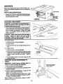
assembly
Before mounting the saw on legs, a stand or a bench, the
Table Insert and Blade Squareness must be checked at
tt_s time.
INSTALUNG
LOCKWASHER
HANDWHEELS
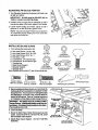
1. Line up FLAT SPOTS on shaft and Handwheel, Push
Handwheelonto shaft. Install screw and Iockwasher
to lock Handwheel on shaft.
10-32 X 314 IN.
/
ELEVATION
HANDWHEEL
CHECKING
PHILLIPS
HEAD SCREW
TI L'F HANDWHEEL
TABLE INSERT
make sure switch Is "OFF" and plug is not coni WARNING: To avoid Injury lrom accidental _rt,
nected to power source outlet.
1. Insert should beflushwithtabletop, Chsck as shown.
Loosen flat head screw that holds inert and adjust the
four set screws as necessary. Tighten flat head
screw. Do not tighten screw to the point where it
deflects the insert.
CAUTION: Insert must be even with the table
surface,
inserts too high or low can let the
workplece "snag" or catch on uneven edges.
Workplece could twist and kick back.
i1
2. To remove Insert
A. Make sure saw is off and unplugged.
B. Loosen Screw.
C. Lift Insert from front end, and pull toward front of
saw.
3. To replace Insert.
A. Make sure saw is off and unplugged.
B. Place insert into insert opening in table and push
toward rear of saw to engage springclip and until
keyslot in Insert will drop over screw. Tigl'ten
screw.
C. Do not tighten screw to the point where it will
deflect the Insert.
CHECKING
TABLE
BLADE SQUARENESS
TO
IMPORTANT:
BLADE must be SQUARE (90o)
TABLE, in order to proceed with assembly.
"¢_
MAKE SURE SQUARE
IS NOT TOUCHING
TIP OF TOOTH
/
1. Make sure saw is off and unplugged.
2. TurnElevation Handwheel clockwise until blade is up
/
as highas it will go.
3. Check for BLADE SQUARENESS.
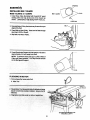
ff blade is not
square to table, adjust it at this time.
NOTE: The combination square must be "true" - see
start of *Unpacking and Checking Contents" section
on page 6 for checking method.
Refer to "Blade Tilt, or Squareness of Blade to Table"
adjustment on page 39.
10
/
ASSEMBLRNG
© G
STEEL LEGS
114 IN EXTERNAL
LOCKWASHER
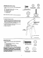
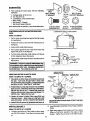
1. From among the loose parts, find the following hardware:
*24
*24
*24
*8
*4
1/4-20
HEX NUT
114-20 x 1/2 IN.
TRUSS HEAD SCREW
Truss Head Screws, 1/4-20 x 1/2" long
Lockwasher, 1t4 External
Hex Nuts, 1/4-20
Hex Nuts, 3/8-16
Leveling Feet
Items marked with an asterik (*) are shown actual size.
318-16
HEX NUT
LEVELING FOOT
2. Assemble the legs as shown.
insert the Truss Head Screws through the holes in the
legs, then through the holes in the Stiffeners. MAKE
SURE THE SCREWS GO THROUGH THE HOLES
IN THE SIDE STIFFENERS MARKED "X".
ASSEMBLE
THROUGH
MARKED"X"
3. Install the Iockwasher, screw on the nuts but do not
tighten until completely assembled.
SIDE
SCREWS
HOLES
STIFFENER
4. Install Leveling Feet.
END
STIFFENER
IN. HEX NUTS
MOUNTING
SAW
1. From among the loose parts, find the following hardware:
*4
*4
*4
*8
Hex Head Screws, 5/16-18 x 1ol14"!ong
Hex Nuts, 5t16-18
Lockwasher, 5/16 External Type
Flat Washers, 11/32x 11/16 x 1/16
HEX HEAD SCREW
Items marked with an astedsk (*) are strewn actual size.
WARNING:
The saw Is heavy.
To avoid back
Injury, get help to lift the saw. Hold the saw close
to your body. Bend your knees so you can lift with
your legs, not your back.
t
!1
5tt6-18
HEX NUT
Q
5116 IN EXTERNAL
LOCKWASHER
FLAT WASHER
assembly
SAW._ IBASE
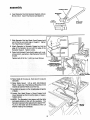
2. Place saw on legs so that holes in bottom of saw line
up with holes in top of legs.
3. Install screws, washers,
shown.
HEX
HEAD
SCREW
t
"'--_l
Iockwashers and nuts as
FLAT
WASHER
__
END
STIFFENER-_i
_
__
LOCKWASHER
.
, "1
""_'
' '
/
/
/
7/16 DIA. HOLES
/
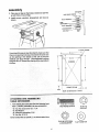
If you mount the saw on any other bench, make sure that
there is an opening in the top of the bench the same size
as the opening in the bottom of the saw so that the
sawdust can drop through_ Recommended working
height is 33 to 37 inches fromthetopof
the saw table to
the floor.
F
7- @
13
16
/
I I, ,
/"
\\
FRONT
OF SAW
\
®
--'_
__
1/2
2-3/4
NOTE:
All dimensions
@
ATTACHING AND ASSEMBLING
TABLE EXTENSIONS
1. Fromamongthe loose parts findthe following hardware: (Quantity indicated isfor two extensions)
*8
*8
*8
"8
in inches
HEX HEAD SCREW
Hex Hd. Screw 5/16-18 x 1-1/4
Flat Washer
External Lockwasher, 5/16
Hex Nut, 5t16-18
5t16-18
HEX NUT
O
Items marked with an asterik (*) are shown actual size.
5/16 IN EXTERNAL
LOCKWASH ER
12
FLAT WASHER
2. Insert four (4) 5/16-18xl
hole in each Extension.
114 in. long screws through
3. Position extension against table so screws
through hole in table.
4. Install flat washers, Iockwashers,
screws...DO NOT TIGHTEN.
extend
and nuts on the
!
5. Line up the rear edge of extension with the rear edge of
the table and top surface of the extension with the top
of the table at the spots marked "X" in the drawing. Use
a combination square to line-up these edges. SLIGHTLY
TIGHTEN nuts with a 1/2" wrench.
CHECK WITH SQUARE
AT 2 PLACES
MARKED WiTH "X"
6. If the side extension is lower in the center than each
end, loosen the center two screws. Using a "C" clamp
(not provided), raise the side of the extension until it is
even with the table surface as shown. Firmly tighten
nuts.
"C" CLAMP
7. Repeat steps 2 thru 6 to install the other extension.
I I
MOUNTING
SWITCH
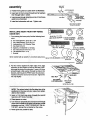
1. From among loose parts findthe following:
*2 Hex Head Screw 5/16-18 x 3/4
5116-18 x 3/4
HEX HEAD SCREW 21164 IN WASHER
*2 Flat washers. 21/64 x 5/8 x 1/16
*2 External Lockwashers, 5/16
*2 Hex Nuts, 5/16-18
HE)( NUT
5/16 iN
Items marked with an asterisk(*) are shown actual size.
13
LOCK WASHER
5/16 IN EXTERNAL
JAM NUT
5/16-18
assembly
1
L OCKWASHER
2. Position front guide bar upside down as illustrated.
_/"
3. Insert two 3/4 inch screws through two flat washers
then through holes in switch.
7 5TH HOLE
J
_'\
6TH HOLE
4. Insert screws through holesfive and six in frontfence
guide bar as illustrated.
_
',- \_.__-_
FRONT
FENCE
GUIDE
BAR
(UPSIDE
5. Install two Iockwasher and nuts. Tighten nuts.
%%"_""-
W ASH E R
HEX HEAD
5/16-18
iNSTALLiNG
GUIDE BAR
RIGHT FRONT
DOWN)
SCREW
x 3/4
IN.
RIP FENCE
5/16-18 x 1-t/4 IN
HEX HEAD SCREW
1. From among the loose parts, find the following hardware:
*2
"1
*4
*4
Hex Head Screws, 5/16-18x 1-3/4
Hex Head Screws, 5/16-18x 3/4
Lockwashers, 5/16 External Type
Hex Nuts 5/16-18
"3
"1
*2
1
Spacers, 3/4 diameterx 1/2 long
Hex Head Screw 5/16-18 x 1-1/4
Flat Washers 5/8 x 1/16
Bracket
Items marked with an asterik (*) are shown actual size.
5/16 IN
HEX NUT
5/16 IN EXTERNAL
LOCK WASHER
HEX HD. SCREW
5/16-18 x 3/4 IN
HEX HEAD SCREW
5/8 x 1/16 IN WASHER 314 IN. DIA. X 112IN.
SPACER
=
2. Put the bracket against the right edge of the right
extension so the bracket is lined up with the FIRST
hole near the front of the extension. Insert a 3/4 long
screw through a flat washer, through top hole in the
bracket, and throughthe FIRST hole in the extension.
BRACKET
"_
Installa
nuton thescrew, Tightenthe
nut only lockwasherand
slightly.
-- ---"--_
T_,,_ _, _/_
EXTERNAL
LOCKWASHER
_ 1WASHER
HEX HEAD
SCREW
5/16-18 x 3/4 IN
NOTE: The various holes in the Bar allow them to be
positioned on the saw and also makes them adaptable to other models.
t
3. Insert a 1-314 inch long screw through the second
hole from LEFT Inthe Front Bar.
_'CENTER HOLE :
'\
IN TABLE
2ND HOLE
IN BAR
5. Turn front bar perpendicular and insert bolt through
center hole in middleof saw table as illustrated. Install
lockwasher and nut. DON'T SCREW NUT ON ALL
THE 'NAY, just get the nut started on the screw.
_f
6. Rotate guide bar parallel to table.
14
;P
4TH HOLE
IN BAR
7. Insert 1-1/4 inch long screw through slot in bar that
matches hole in bracket. Install spacer, Iockwasher
and nut. DON'T SCREW NUT ON ALL THE WAY,
just get the nut started on the screw.
NUT
HEX HEAD SCREW
5/16-8 X 1-3/4 IN.
8. Install spacer between guide bar and the last front
table hole which aligns with the fourth hole in the front
guide bar.
scREW
5/16-8 X 1-3/4 IN.
9. Insert 1-3/4 inch long screw through the hole in bar,
spacer and hole in table. Install Iockwasher and nut
but do not tighten.
iNSTALLiNG
1.
REAR FENCE
LOCKWASHER
GUIDE BAR
From among the loose parts find the following:
1 Bracket
*2 Hex Head Screws 5/16-18 x 1
*2 Hex Head Screws 5/16-18 x 3/4
*4 Flat Washers 5/8 x 1/16
*4
External Lockwashers 5/16
*4 Hex Nuts, 5/16-18
1 Rear Fence Guide Bar
Items marked with an astedk (*) are shown actual size.
5/16-18 x ! IN
HEX HD. SCREW
5/16 IN
EXTERNAL
LOCKWASHER
5/16-18 x 3/4
HEx HEAD
FLATWASHER
5/16-18
HEX NUT
REAR FENCE GUIDE BAR
BRACKET
REAR OF
2. Put the bracket against the right rear edge of the right
extension so the bracket is lined up with the FOURTH
hole near the rear of the extension (see illustration).
EXTENSION
4TH HOLE
_
3. Insert one of the 3/4 inch long screws through a flat
washer, through the bracket, and through the FOURTH
hole in the extension. Install a Iockwasher and nut on
_
\_/_
WASHER
the screw. Tighten the nut only slightly.
LOCKWASHER
4. Insert a 1 inch long screw through a flat washer and
through the fourth hole of the rear fence guide bar.
Turn rear bar perpendicular to table and insertscrew
through the middle hole as illustrated. Install
Iockwasher and nut loose to adjust guide bar to the
horizontal position.
LOCKWASH_UT
11TH HOLE_,.,I-_._
_,:OC
5/16-18 x 3/4
HEX HEAD
SCREW
\KWA_
"-7_'''_-_------_-Vj-_T-_
-
5. Insert a 3/4 inchlong screwthrough a flat washer, bar,
and bracket. Install Iockwasher and nut but do not
tighten.
HEX HEAD SCREW
5/16-18 X 3/4
6. Insert 1 inch long screw through a flat washer and
through the second hole of the rear fence guide bar
plus through the matching hole in table. Install
Iockwasher and nut loosely.
15
WASHER i
HEX HEAD SCREW
5/16-18 X 1 IN.
HEX HEAD SCREW
5/16-18 X 1
assembly
7. Position Rip Fence over Miter Gauge Groove, holding
up the rear end while engaging front end with Bar.
Lower Fence onto table.
8.
Raise blade all the way up,
9.
Carefully move Fence against blade.
8THICKNESSES
OF PAPER
t0, Move Front Bar until "0" mark on Rip Scale is
approximately in line withtip of Pointer.
11. Mov e Front Bar upwards until Fence is approximately 1/32 inch above table, Tighten screw at left
end of Bar.
NOTE: Fold a piece of newspaper making 8 thicknesses and place between Rip Fence and table to
act as a spacer. This will hold the Fence off of the
table approximately 1/32 inch.
o
12. Adjust Rear Barso thal the Fence is approximately
1132 inch above table, make sure it is square with
MiterGauge Groove. Tighten screw atend of Bar.
8 THICKNESSES
OF PAPER
13. Move Fence to RIGHT edge of table. Make sure it is
approximately 1/32 inch above table at front and
rear and tighten screws.
t6
ALIGNING
RiP FENCE
The Fence should slide easily along the Bars and always
remain in alignment (parallel to sawblade and Miter
Gauge Grooves),
The alignment is maintained by a spring underneath the
Fence which bears against the Front Guide Bar.
To move the Fence, loosen the Lock Handle and grasp
the Fence with one hand at the front.
For very close adjustments, grasp the Guide Bar with
both hands and move the Fence with your thumbs.
\
SELF ALIGNING
SPRING
ADJUSTMENT
Place Fence on saw but DO NOT LOCK IT.
Move the REAR END of the Fence slightlyto the right or
left. When you release it, the Fence should "spring"back
to its original position.
if itdoes not, the spring pressure must be INCREASED,
1. Loosen the screws.
2. Move spring slightly toward front of Fence. Tighten
screws.
backs and jams. To avoid injury, follow these
instructions until the fence properly self aligns.
17
assembly
If the Fence does not slide easily along the Bars, the
pressure of the spring can be REDUCED.
1. Loosen the screws.
2. Move spring slightly toward rear of Fence.
Tighten
screws.
WARNING: To avoid Injury from jams or kickbacks, be sure to push properly adjusted Lock
Lever all the way down untllthe laver rests onthe
stop before using the Rip Fence.
SPRING
SLIDE SPRING TO
ADJUST PRESSURE
RiP FENCE
LOCK LEVER ADJUSTMENT
The Rip Fence Lock Lever, when locked down, should
hold the Rip Fence securely, it should not be difficultto
push down and lock.
If LOCkLever does not Iockfence securely:
1. Raise Lock Lever.
2. Tighten the adjusting nut using a small screwdriver
until the lever, when locked, holds the Rip Fence
securely.
If Lock Lever is difficultto push down:
1. Raise Lock Lever.
2. Loosen the adjusting nut using a small screwdriver
until the lever is easy to push down and holds the Rip
Fence securely.
RIP FENCE
ALIGNMENT
ADJUSTMENT
1. The Rip Fence must be PARALLEL with the
sawblade and Miter Gauge Grooves. Move Fence
until it is along side of Groove. DO NOT LOCK IT. It
should be parallel to Groove. If it is not;
HEX SCREWS
FENCE HEAD
/
A. Loosen the two Hex Hal. Screws.
B. Hold Fenceheadtightlyagainst Bar. Move end of
Fence sothat it is parallel with Groove.
C. Altemately tighten the screws.
D_Recheck alignment.
E. Repeat steps as needed.
\
backs and jams. To avoid Injury, follow these
i Instructions
ARNING: A
misaligned
can cause
kick- I
until
the fencefence
is properly
aligned.
18
ADJUSTmNG RiP SCALE
POINTER
1. Turn Elevation Handwheel clockwise until blade is up
as high as it will go.
IMPORTANT: BLADE must be SQUARE (90 °) to
TABLE, in order to ALIGN Rip Scale.
LOCK HANDLE F
2. Position Fence on right side of sawblade so that it
touches the sides of the teeth, tighten Lock Handle.
3. Loosen screw holding the Pointer, adjust so that it
points to "0" on the Rip Scale, tighten screw.
NOTE: It you cannot adjust Pointer so that it points to
"0", loosen the screws holding the Front Guide Bar
and move the Guide Bar.
INSTALLING
\
\
\
\
BLADE GUARD
1. From among the loose parts, find:
"2 Hex Head Screws, 1/4-20 x 5/8
1/4-20
*3 Hex Head Screws, 5/16-18 x 5/8
HEX NUT
*2 Hex Head Screws, 5/16-18 x 1
*2 Hex Nuts, 1/4-20
k--J_'_
"2 Lockwashers, 1/4 External Type
*2 Lockwashers, 5/16 External Type
"1 Thumbscrew
1 Blade Guard Support
5/16 IN.
1 Spreader Support
EXTERNAL
1 Spreader Rod
LOCKWASHER
Items marked with an asterik (*) are shown actual size.
\
©
1/4 IN.
EXTERNAL
LOCKWASHER
BLADE GUARD
SUPPPORT
THUMBSCREW
LI
1/4-20 X 5/8 IN.
HEX HD. SCREW
5/16-18 X5/8 IN.
HEX HD. SCREW
5/16-18 X 1 IN.
HEX HD. SCREW
2. Before installingthe BladeGuard, you mustcheckthe
heeling adjustment (parallelism of sawblade to Miter
Gauge Groove). The procedure for makingthis check
and adjusting it are found in the "ADJUSTMENTS"
section of this manual. Refer to "Heeling Adjustment
or Parallelism ofSaw Blade to Miter Gauge Groove."
WARNING: The blade must be parallel to Miter
Gauge Groove. Mlsaligned blades could bind on
workplace. Workplace could suddenly kick back.
You could be cut or hit.
3. Lower the blade.
4. Screw the Motor Base Clamp Screws part way into
cradle. Screw the 5/16-18 x 5/8 inch Hex Hd. screw
intothe Blade Guard support.
5. Attach Blade Guard Support.
SCREWS.
DO NOT TIGHTEN
19
SPREADER ROD
SPREADER SUPPORT
assembly
TH LIMB SCREW
\
SPREADER
6. Insert Spreader Rod into Spreader Support until pin
fits into notch. Insert Thumbscrew and tighten it.
_
ROD
\
\
FLAT
SURFACE
SPREADER
SUPPORT
(INTO SUPPORT)
II
7. Slide Spreader Rod into Blade Guard Support until
end of Rod is even with edge of Support, Tighten
Hex Head Screw in Support.
8. Attach Spreader to Spreader Support so that the
edge of the Spreader is ever_ with the edge of the
Spreader Support. Tighten screws.
9. Raise Anti-Kickback Pawls (hold in place with a setscrewwrench-see below). AlignSpreaderSQUARE
to table.
Tighten both 5/16-18 x I inch Hex Head Screws.
1/4-20
HE](
HD. SCREW
1/4 IN. LOCKWASHER
1 !4-20
HEX
NUT
EVEN WITH SPREADER
SUPPORT EDGE
END OF ROD
EVEN WITH EDGE
OF SUPPORT
J
5/16-18 X 1 IN.
HEX HD. SCREWS
10. Raise blade all the way up, make sure it is square
with table.
11.Raise Blade Guard. Lift up both Anti-Kickback
Pawls. Insert one of the Setscrew Wrenches in the
notches to hold the Pawls out of the way.
12.Lay blade of square or other straightedge alongside
of blade.
13.Loosen Hex Head Screw in Guard Support and
move Spreader so that it touches blade of square.
Tighten screw.
and approximately in line with the sawblade. The
Spreader requires further adjustment to alignit PARALLEL to the blade and in the MIDDLE of the cut
(KERF) made by the sawblade.
SCREW
KERF
WOOD
15.iMPORTANT:
To work properly, the Spreader
must always be adjusted so the cut workplece
will pass on either side at the Spreader without
binding or skewing to the side.
NOTE: The Spreader isthinner than the width of the
cut (KERF) by approximately six thicknesses of
paper.
/
SPREADER
LOOKING
DOWN ON SAW
16. Make two folds in a small piece (6 x 6 inch)of ordinary
NEWSPAPER making three thicknesses.
The folded paper will be used as a "spacing gauge".
17. Place Rip Fence on table. CAREFULLY move it
against blade so that it is parallel to the blade, and
just TOUCHES tips of saw teeth. Tighten Rip Fence
Lock Lever.
l
FOLDED
PAPER
18. Insert folded paper between Spreader and Fence.
19.Using 7/16 wrench loosen the 114-20 hex head
screws so the Spreader can slide sideways.
20. Hold Spreader flat against Fence. Tighten screws
using 7/16 inch wrench.
21.To remove Blade Guard and Spreader, loosen
Thumbscrew. DO NOT LOOSEN OTHER SCREWS.
This lets you remove and replace the Guard without
disturbing the Spreader alignment.
MOUNTING
7/16 IN. WRENCH
THE MOTOR
Model 113.298722
& 113.298762
KEY
1. The Motor must rotate CLOCKWISE when viewed
_J
from the 5/8 inch shaft.
2, MAKE SURE "KEY' IS REMOVED FROM SHAFT.
,-
3.
Place
the Motor
on your workbench or on the floor.
Check
Motor
Rotation
_//__,_
"MOTOR SPECIFICATIONS
AND ELECTRICAL
4. Plug
the cord into asection)
properly grounded
(See
REQUIREMENTS"
Notice the outlet
rotation
of
the shaft. If it is not turning CLOCKWISE, do not
assemble or attempt to operate saw until motor with
correct rotation is obtained.
/
5/8 IN.
DIA. SHAFT
21
/
_
_0TAI.jON
assembty
5. From among the loose parts, find the following
hardware:
*4
*4
°4
1
1
1
Carriage Bolts, 5116-18 x 3/4
He× Nuts 5/16-18
Lockwashers, 5t16 External Type
Motor Pulley
Belt Guard "L" Bracket
Belt Guard Support Bracket
ONLY
BELT GUARD
"L" BRACKET
MOTOR
PULLEY
BELT GUARD
SUPPORT BRACKET
G
items marked with an astedsk (*) are shown actual size.
5/16-18 x 3/4 IN
CARRIAGE BOLT
5/16-18
HEX NUT
5/16 IN EXTERNAL
LOCKWASHER
i
POSITIONING MOTOR ON MOTOR MOUNTING
BASE
LOOSEN BOTH CRADLE CLAMP SCREWS
Modet 113.298762
1. Put the motor mounting base against theflat sudace
o! a workbench.
2. Position the motor so the end with terminal cover is
facing you.
3. Loosen both cradle clamp screws.
4. Put a square against the LEFT side of the motor and
against the top of the workbench.
5. Turn the motor inside the cradle clamps until the top
of both capacitors touch the square.
6. Tighten both cradle clamp screws to hold the motor in
this position.
'_ MOTOR M2#NTING
HAS
SQUARE __
_,-_-_+_1"_1
o
I
WORKBENCH
let workpleca strike capacitor cover during bevel
or
compoundFailure
miter to
cuts.
Workpleca
could biml
I WARNING:
properly
InStall motor
may
and kick back. You could be cUt or hit.
WELDED MOTOR
MOUNTING BASE
MOUNTING MOTOR ON MOTOR BASE
I
Model 113.298722 & 113.298762
THESE TWO
EDGES EVEN
CARRIAGE
BOLT
5t16-18 X 3/4 IN.
LOCKWASHER
5/16 IN,
1. Place Motoron Motor Base so that shaft is pointingto
the right. Insert bolls through holes in Base, then
through the Motor Mounting Base. Install Iockwashe_
and nuts, DO NOT TIGHTEN AT THIS TIME.
N "l" _'N_,_.J"3
u _._.=_ _
5/16-18
2. Position Motor so that edge of Motor Foot and Motor
Base are even. Slide Motor all the way tothe RIGHT.
Slip the long part of the "L" Bracket fully under the
Motor so the short part is just under shaft (Model 113.
298722 only). Tighten the four nuts.
3ASE
BELT GUARD
INSERTED
EVEN WITH
MOTOR END HUB
away from Motor. DO NOT TIGHTEN SETSCREW.
grooves in Pulley and rnotorshaft. DO NOTTIGHTEN
SETSCREW.
4. Install 3/16 inch square key (furnished with Motor) in
INSTALLING
2. Lowerthe blade, install Belt on Saw Pulley and Motor
BELT
Pulley.
Model 113.298722 & 113.298762
3. Sight along edges of both pulleys and move Motor
Pulley so that belt is parallel to the edges of both
Pulleys. Tighten the set screw in the Motor Pulley.
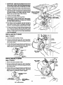
1. Lift Motor and insert the TWO PINS on Motor Base
into HOLES in Cradle. Push Motor in as far as it will
go.
22
4. iMPORTANT: Measure the distance from end of
Motor sha_ to Pulisy. Mark this dimension down;
you will need It later when reinstalling the Pulley.
5. Make sure blade is90 ° totable, raise italltheway up.
6. Lift Motor until edge of washer iseven with end of slot
tighten pivot screw. In this position, pull Motor toward
you (pins will slide out of Cradle) until Bell is TIGHT,
tighten the two Motor Base Clamp Screws.
EDGE OF WASHER
EVEN WITH END
OF SLOT
7. Loosen Pivot Screw slightly.
8. Lower the saw blade all the way down.
.
9. IMPORTANT: Motor should pivot freely downward as blade Is lowered, if it does not, LOOSEN
the Pivot Screw some more.
MOTOR BASE
CLAMP SCREWS_
10, Pivot Screw must be adjusted only tight enough to
allow Motor to pivot FREELY as blade is raised and
lowered. Thiswill maintain constant tension on Belt.
SCREW
/
11. Put your hand around the belt half way between the
two Pulleys and squeeze Belt until two sides of Belt
touch. The Motor should move freely as you squeeze
the Belt. If Motor does not move freely, Belt tension
must be readjusted.
INSTALLING
BELT
"L" BRACKET
MOTOR
PULLEY
GUARD
Model 113.298722
1. Remove the Belt and Motor Pulley.
PIVOT
SCREW
2. Screws furnished with Guard are "Serf Threading".
Screw them intoholes in Belt Guard Support Bracket,
then remove them.
3, Position Belt Guard Support Bracket and Belt Guard
Support as shown and installthe screws. Make sure
Motor shaft is in CENTER of hole in Support.
TWO
HOLES
CLOSEST
BELT GUARD
SUPPORT
BELT
SUPPORT
GU/_RO
BRACKEt
BELT GUARO
INSTALLING
SUPPORT
10-32 X 1 tt IN*
SELF-THREADING
SCREW
BELT GUARD
Model 113.298762
BELT GUARD
1. Remove the Belt and Motor Pulley.
2. Screws furnished with Guard are Self Threading."
Screw them intoholes in Belt Guard Support Bracket,
then remove them.
PIVOT
SCREW
3. Position Belt Guard Support Bracket and Belt Guard
Support as shown and installthe screws. Make sure
Motor Shaft is in CENTER of hole in support.
"_
TWO HOLES
TOGETHER
CLOSEST
/
CENTERED
BELTGUARD
SUPPORT BRACKET
23
BELT GUARD
SUPPORT
j
OPENING
/-
assembly
INSTALUNG
BELT GUARD
Model 113.298722 & 113.298762
BELT GUARD
1. Install three Clips (furnished with Guard) 90' apart
starting wHh one Clip at the end of the Guard as
shown. LONG END of Clip facing AWAY from you.
_
CLIPS
\
LONG END
BELT
2. Reinstall Motor Pulley thesame way it was when you
aligned the Belt.
3. Place Belt on Saw Pulley. insert end of Belt through
opening in END of Guard.
4. Slip Belt over Motor Pulley.
5. Press Guard onto Support sothat bottom of Guard is
approximately 3/4 inch away from Belt.
NOTE: To remove Guard, lift upon LONG TABS of
Clips, pull Guard outward. The Clips should remain
on the Belt guard Support.
3/4 iN.
PLUGGING
IN MOTOR
1. From among the loose parts find:
2 Wire Ties
wire ties.
WIRE TIES
EXTENSION REMOVED FOR
PICTURE CLARITY
24
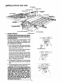
geeing to know your saw
9 SAWeLADE
J
8
10
TABLE
7
BLADE
GUARD
INSERT
EXACT-I-CUT
ANTIKICKBACK
PAWLS
6
MITER
GAUGE
RIP FENCE
HOLES
ATTACHING
RiP FENCE
LOCK HANDLE
'4
TILT LOCK HANDLE
(UNDERNEATH
TABLE)
2
ELEVATION
\
HANDWHEEL
3
\
ON-OFF
SWITCH
TILT HANDWHEEL
1 ON-OFF
SWITCH
sure the blade guard is correc.y Installed and
CAUTION:
Beforetuming switch "ON", make
operating properly.
The On-Off Switch has a locking feature. THIS
FEATURE IS INTENDED TO PREVENT UNAUTHORIZED AND POSSIBLE HAZARDOUS USE
BY CHILDREN AND OTHERS.
A. To turn saw ON, stand to either side of the blade,
never in line with it, insert finger under switch
lever and pull END of lever out.
(YELLOW
KEY
PLASTIC)
After turning switch ON, always allowthe blade to
come up to full speed before cutting.
Do not cycle the Motor Switch on and off rapidly,
as this may cause the sawblade to loosen. Inthe
event this should ever occur, allow the sawblade
to come to a complete stop and retighten the
arbor nut normally, not excessively. Never leave
the saw while the power in "ON".
f
B. To turn saw OFF, PUSH lever in. Never leave the
saw until the cutting tool has come to a complete
stop.
C. To lock switch inOFF position,hold switch IN with
one hand, REMOVE key with other hand.
WARNING: Foryourown safety, lower blacis
or other cutting tool below table surface. (if
blade is tilled, return R to vertloal, 90 °, posF
tlon.) Always lock the s_ltch "OFF". When
saw Is not In use, remove key and keep it in a
e place. Also, in the event of is power
lure (all of your lights go out) turn switch
oft, lock It and rentove the key. Tide w!lll
prevent the saw from starting up again when
the power comes back on.
25
__y
FOR
FACING
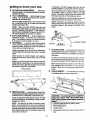
getting to know your saw
2
ELEVATION
HANDWHEEL
...
If necessary, the Miter Gauge head can then be
swiveled slightly to compensate and then locked,
elevatesor
Slots are provided in the Miter Gauge for attaching
an Auxiliary Facing to make it easier to cut long
pieces. Be positive Facing does not interfere with
the proper operation of the Sawblade Guard.
Iowersthe blade. Turnclockwiseto elevate, counterclockwise to lower.
3 TILTHANDWHEEL...tiltstheblade
forbevel
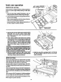
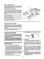
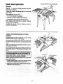
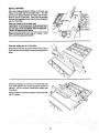
4
5
cutting. Tum clockwise to tilt toward left, counterclockwise to tilt toward right.
Select a suitable piece of smooth straight wood, drill
two holes through it and attach it with screws
When the blade is tilted to the LEFT as far as itwill
go, it should be at 45 ° to the table and the bevel
pointer should point 45 °.
NOTE: When bevel crosscutting, attach Facing so
that it extendslo the right of the Miter Gauge and use
the Miter Gauge in the groove to the right of the
blade.
NOTE: There are LIMIT STOPS inside the saw
which prevent the blade from tilting beyond 45 ° to
the LEFT and 90 ° to the RIGHT. ( See "ADJUSTMENTSAND ALIGNMENTS" section"BLADE TILT.
OR SQUARENESS OF BLADE TO TABLE").
TILT LOCK HANDLE...
locks thebladeint he
desired tilt position. To loosen, turn counterclockwise. Push handle in and turn it to another position
if necessary in order to tighten or loosen.
_'_Ry
RIP FENCE...
isk_ckedin place bypushingthe
LockLeverdownuntilthe lever rests onthestop. To
move the Fence, lift the Lock Lever and grasp the
Fence with one hand at the front.
STOP Pill
7
Holes are provided in the Rip Fence for attaching a
wood facing when using the Dado Head, or Molding
Head.
Select a piece of smooth straight wood approximately 3/4 inch thick, and the same size as the Rip
Fence.
\.
I J
_J___
BLADEGUARD
...must always be in place and
working properly for all thru-sawing cuts. That is, all
cuts where the blade cuts completely through the
workpiece.
To remove the Guard for special operations loosen
the Thumbscrew and slidethe Guard off of the Rod.
DO NOT DISTURB THE SETTING OF THE ROD.
Attach it to the Fence with three Round Head #10
Wood Screws, 2 inches long. To remove the facing,
loosen the screws, slide the facing forward and pull
the screws through the round holes.
WOOD
450 SLOT
FOR STOP PIN
FACING
When replacing the Guard, make sure the PIN in the
Rod engages with the NOTCH in the Spreader
Support. Make sure Thumbscrew is tightened securely.
FACING
8
TAB LE iNSERT
... is removable for removing
or installing blades or other cutting tools
\
\
•
"
\
/
.//
_
ROUND HEAD
._
# 10 WOOD SCREWS
./
SCREW
6 MITER GAUGE...
headis Iockedinpositionfor
cmsscuttingor mitering bytightening the Lock Knob.
ALWAYS LOCK IT SECURELY WHEN IN USE.
! WARNING: TO avoid Inj_ from accidental
start, turn switch "OFF' and remove plug
I
NOTE: The slots forthe Stop Pin andthe graduations are manufactured to very close tolerances
which provide accuracy for average woodworking.
In some cases where extreme accuracy is required,
when making angle cuts, for example, make a trial
cut and then recheck it.
po,, r
A_. Lowerthe blade below the table surface.
B. Raise Biade GUard.
C. Loosen screw.
D. Lift insert from front end, and pull toward front of
saw.
26
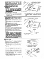
NEVER OPERATE THE SAW WITHOUT THE
PROPER iNSERT IN PLACE. USE THE SAWBLADE INSERT WHEN SAWING.
USE THE
COMBINATION DADO MOLDING INSERT WHEN
USING A DADO OR MOLDING HEAD.
9
REMOVIHG
SAWBLADE
WARNING:
BLADE GUARD NOT SHOWN
FOR PICTURE CLARITY
AND INSTALLING
To _wv_d injury from accldentaI
start, _m _Rch
_om pawmr_
"OFF" and remove plug
ouUst _m
removing or
Installing _.
WOOD BLOCK
A. Raise Blade Guard, remove Insert.
B. To REMOVE Blade, place a block of wood against
front of Blade, PULL arbor wrench toward you to
LOOSEN arbor nut.
C. To TIGHTEN arbor nut, place a block of wood
against rear of Blade, PUSH wrench away from
you.
When installing the Blade, make sure the teeth are
pointing toward the front of the saw and that the
Blade and Collars are clean, and free from any
burrs.
BLADE GUARD NOT SHOWN
PICTURE CLARITY
The HOLLOW side of the collar must be against the
Blade.
Always tighten the arbor nut securely.
NOTE: When using the Dado or Molding Head, it is
not necessary to install the loose Collar.
To replace insert.
Place insert into opening in table and push toward
rear of saw to engage Spring Clip and until keyslot
in insert will drop over screw. Tighten screw.
OR NUT
LOOSE
COLLAR
ARBOR
Do not tighten screw to the point where it will deflect
the insert.
ARBOR
WARNING: To avoid injury from a thrown
workplece, blade parts, or b_ade contact,
NEVER operate saw withou_ the proper insert
In place. Use the sa_ie
Ir_sert when =awing. Use the proper size Dado/Moldlng
for dado blades and molding heads.
TEETH
POINTING
TO -.._.
FRONT
OF SAW
.
,,%.
... _-_
_.
10 EXACT-I-CUT
The "yellow" Plastic Disc imbedded in the table in
front of the sawblade, is provided for marking the
location of the 'sawcut" on the workpiece.
A. Check Disc. If it is above table surface, place a
piece of hardwood on top of it and tap it down.
BLADE GUARD NOT SHOWN
FOR PICTURE CLARITY
B. With blade 90 ° (square to table) cross cut a piece
of wood.
C. Pull Miter Gauge back until wood is over Disc.
Using a sharp pencil, mark a line on Disc.
D. With Miter Gauge in right hand groove, follow
same procedure and mark another line on Disc.
E. These lines indicate the "'path" of the cut (kerr)
made by the sawblade.
F. When cutting the workpiece,
workpiece with line on Disc.
line up mark on
27
NUT
safety instructions for basic saw operations
BEFORE
EACH USE:
1. inspect your saw
5. Adjust table inserts flush with the table top.
NEVER use the saw without the proper insert.
A. To avoid injurytram accidental starting,unplug the
saw, turnthe switch off and remove the Switch Key
before raising or removing the Guard, changing
the cutting tool, changing the setup or adjusting
anything.
6. Makesure allclamps and locks are tight and no
parts have any excessive play.
2. Keep work area clean
A. Cluttered areas and benches invite accidents.
FlOor must not be slippery from wax or sawdust.
B. Check for alignment of moving parts, binding of
moving parts, breakage of parts, mounting, and
any other conditions that may affect the way it
works, tfany part ismissing, bent, or broken in any
way, or any electrical parts don't work properly,
turn the saw off and unplug the saw.
B. To avoid burns or other fire damage, never use the
saw near flammable liquids, vapors or gases.
C. To avoid injury, don't do layout, assembly, or setup
work on the table while the blade is spinning. It
could cut or throw anything hitting the blade.
AVOID ACCIDENTAL STARTING - Make sure
C. Replace damaged, missing, or failed parts before
using the saw again.
switch is "OFF" before plugging saw in.
D. Use the Sawblade Guard, Spreader, and AntiKickback Pawls for any thru-sawing (wheneverthe
blade comes through the top of the workpiece).
Makesurethe Pawlsworkpmperly. Makesurethe
Spreader is in line with the sawblade.
E. REMOVE ADJ USTING KEYS AND WRENCHES.
Form habit of checking forand removing keys and
adjusting wrenches from tool before turning it on.
Plan ahead to protect your eyes, hands, face, ears.
3. Plan your work
A. USE THE RIGHT TOOL - Don't force tool or
attachment to do a job it was not designed for.
B. Dress for safety:
1. Do not wearloose clothing, gloves, neckties or
jewelry (rings, wristwatches). They can get
caught and draw you into moving parts.
2. VVear nonslip footwear.
F. To avoid injury from jams, slips or thrown pieces
(kickback and throwback):
1. USEONLY RECOMMENDEDACCESSORIES
(See page 40). Follow the instructions that
come with the accessories. Using other accessories may be dangerous.
3. Tie back long hair.
4. Roll long sleeves above the elbow.
5. Noise levels vary widely. To avoid possible
hearing damage, wear ear plugs or muffs when
using saw for long periods of time.
2. Choose the right blade or cutting accessory for
the material and the type of cutting you plan to
do.
6. Any power saw can throw foreign objects into
the eyes. This can cause permanent eye damage. Wear safety goggles (not glasses) that
........
ANSI Z87.1 (shown on package).
Everyday eyeglasses have only impact resistant lenses. They are not safety glasses. Safety
goggles are available at Sears retail catalog
stores. Glasses or goggles not in compliance
with ANSI Z87.1 could seriously hurt you when
they break.
3. Never use grinding wheels, abrasive cut-off
wheels, friction wheels (metal slitting blades)
wire wheels or buflingwheel. They can fly apart
explosively.
4. Choose and inspect your cutting tool carefully.
a. To avoid cutting tool failure andt hrown shrapnel (broken pieces of blade), use only 10" or
smaller blades or othercutting tools marked
for speeds of 3450 rpm or higher.
b. Always use unbroken, balanced blades designed to fit this saw's 5/8 inch arbor.
c. When thru-sawing (making cuts where the
blade comes through the workpiece top),
always use a 10 inch diameter blade. This
keeps the Spreader in closest to the blade.
d. Do not overtighten arbor nut. Use arbor
wrenches to "snug" itsecureiy.
e. Use onlysharp blades withpropedy setteeth ....
Consult a professional bladesharpenerwhen
in doubt.
f. Keep blades clean of gum and resin.
28
nailsor foreign objects in the part of the workpiece
to be cut.
D.PlanyourcuttoavoidKICKBACKS
andTHROWBACKS - when a part or all of the workpiece binds
on the blade and is thrown violently back toward
the front of the saw.
F. Push the workpiece against the rotation of the
blade. NEVER feed materiat into the cutting tool
from the rear of the saw.
G.Always push the workpiece all the way past the
sawblade.
1. Never cut FREEHAND: Always use either a
Rip Fence, Miter Gauge or fixture to position
and guide the work, so it won't twist, bind on the
blade and kickback.
H. As much as possible, keep your face and body to
one side of the sawblade, out of linewith a possible
kickback or throwback.
2. Make sure there's no debris between the workpiece and its supports.
WHENEVER
SAW BLADE iS SPiNNiNG
WARNING: Do,'t let familiarity (gained from frequent use of your table saw) cause s careless
mistake. AJways remember that • careless fraction of a second is enough to cause a severe
injury.
3. Whencutting irregularly shaped workpleces,
plan your work so it will not slip and pinch the
blade:
a. A piece of molding, for example, must fieflat
or be held by a fixture or jig that will not let it
twist, rock or slipwhile being cut. Use jigs or
fixtures where needed to prevent workpiece
shifting.
1. Before actuafly cutting with the saw, watch it while it
runs for a short while. If it makes an unfamiliar noise
or vibrates a lot, stop immediately. Turn the saw off.
Unplug the saw. Do not restart until finding and fixing
the problem.
b. Use a different, better suited type of tool for
work that can't be made stable.
2. Make sure the top of the arbor or cutting tool turns
toward the front of the saw.
4. Use extra caution with large, very small or
awkward workpieces:
3. Set the cutting tool as low as possible for the cut
you're planning.
4. KEEP CHILDREN AWAY. All visitors should be kept
a safe distance from work. Make sure bystanders are
clear of the saw and workpiece.
a. Use extra supports (tables, saw horses,
blocks, etc.) for anyworkpieces large enough
to tip when not held down to the table top.
NEVER use another person as a substitute
for a Table Extension, or as additional support for a workpiece that is longer or wider
than the basic saw table, or to help feed,
support or pull the workpiece.
5. Let the blade reach full speed before cutting.
6. DON'T FORCE TOOL. It will do the job better and
safer at its designed rate. Feed the workpiece intothe
blade only fast enough to let it cut without bogging
down or binding.
b. Neverconfinethe piece being cutoff. That is,
the pieceNOTagainstthe Fence, Miter Gauge
or fixture. Never hold it, clamp it, touch it, or
use length stops against it. It must be free to
move. Ifconfined, itcouldgetwodgedagainst
the blade and cause a kickback or throwback.
7. Before freeing any jammed materiah
A. Turn switch '_FF".
B. Unplug the saw.
C. Wail for aft moving parts to stop.
D. Check blade, Spreader and Fence for proper alignment before starting, again.
c. Never cut more than one workpiece at a tirne.
d. NEVER turn the saw "ON" before clearing
the table or all tools, wood scraps, etc.,
except the workpiece and related feed or
support devices for the cut planned.
4. Plan the way you will push theworkpiece through
8. To avoid throwback of cut off pieces;
A. Use the Guard Assembly.
B. To remove loose pieces beneath or trapped inside
the Guard:
1. Turn saw "OFF".
A. NEVER pug the worlkp|ece through. Start and
finish the cut from the front of the table saw.
2. Remove Switch Key.
B. NEVER put your fingers or hands in the path of
the sawblade or other cutting tool.
3. Wait for blade to stop before lifting the Guard.
BEFORE
C. NEVER reach In back of the cutting toolwith either
hand to hold-down or support the workpiece, remove wood scraps, or for any other reason.
LEAVING
THE SAW
1. Turn the saw off.
2. Wait for blade to stop spinning.
3, Make workshop child-proof. Lock the shop. Disconnect master switches. Remove the yellow Switch
Key. Store it away from children and others not
qualified to use the tool.
4. Unplug the saw.
D. Avoid awkward operations and hand positions
where a sudden slipcould cause tinge rs or hand to
move into a sawblade or other cutting tool.
E. DONT OVERREACH. Always keep good footing
and balance.
29
basic saw operation - using the miter gauge
WORK
FEED DEVICES
SLIGHTLY
LESS THAN
THICKNESS
OF WORKPIECE
Before cutting any wood on your saw, study all of the
"Basic Saw Operation."
UP TO 3/8"
As you learn new table saw woodworking techniques,
you'llsee that many types of cuts need different support
and feedingdevices, known as jigsor fixtures. They can
help you make cuts more accurately. By helping to
steadythe workpiece and keep you away from the blade,
they can help you safely use your saw for certain cuts.
45 ° NOTCH
NOTE.
Ai! dimenstons
in inches
PUSH STICK
Many people custom build their own jigs and fixtures.
Jigs and fixtures areoflen unique,designed for a particular CUt.
THESE EDGES MUST
BE PARALLEL
3/4 PLYWOOD
4-3/4
You can use yourtable saw to easily make many jigsand
fixtures. To get you started, we've included instructions
for some simple ones. After you have made a few
practice cuts, make up these jigs before sta_ling any
projects. Make the push stick first.
\,
3t8_
2-1/
PUSH STICK AND PUSH BLOCK
5-1/8
Make the Push Stick using a piece of I x 2.
NOTE
3/8
Atl Chmens=ons
3/8 PLYWOOD
in inches
PUSH BLOCK
Make the Push Block using a piece oi3/8 in. and 3!4 in.
plywood.
3/4
PLYWOOD
The small piece of wood 3/8 x 3/8x 1-1/2 inches should
be GLUED to the plywood. DO NOT USE NAILS. This
is to prevent dulling the sawblade in the event you
mistakenly cut into the Push Block.
1-1/4
Pos'dion the handle in the center of the plywood and
fasten together with glue and woodscrews.
AUXILIARY
THIS
FACE AEID
EDGE
MUST
BE
PARALLEL
FENCE/WORKSUPPORT
Make one using apiece of 3/8 inchand 3/4 inch plywood.
Fasten together with glue and flat head woodscrews.
Tighten the screws so the flat head is even with the
bottom of the wood.
3/8
PLYWOOD
5-1/2
NOTE
WOODSCREWS
All
dimension
AUXlUARY
in inches
FENCE/WORK
= =
AUXILIARY PANEL WORK SUPPORT
Make using a piece of 3/4" x 3/8" plywood. Fasten
together with glue and wood screws. Use this Auxiliary
Panel Work Supped only when cutting large panels that
require the Rip Fence to be positioned past the exposed
side of the extension.
3-5/8
MUST BE
PARALLEL
NOTE: All dimension in inches
AUXILIARY PANEL/WORK S_
3O
SUPPORT
2. An auxiliary wood facing attached to the Miter Gauge
can help prevent workpiece twisting and throwbacks.
Attach it to the holes provided. Make the facing long
enough and big enough to support your work. Make
sure, however, it will not interfere with the sawblade
guard.
CROSSCUI-rlNG,
MITER CUTTING, BEVEL CUTTING, COMPOUND MITER CUTTING and when RABBETING across the end of a narrow workplece, the
MITER GAUGE IS USED.
WARNING: For your own safety, a_ays observe I
the following safety precautions In addition to the
safety instructions on pages 2, 3, 4, 5, 29, & 30.
I
ADDNIONAL
SAFETY iNSTRUCTIONS
3. use jigs or fixtures to help hold any piece too small to
extend across the full length of the Miter Gauge face
during the cut. This lets you properly hold the Miter
Gauge and workpiece and helps keep your hands
away from the blade.
FOR
CROSS CUT TYPE CUTS
V_tlle
Before Starting:
Cutting:
1. To avoid blade contact, always hold the Miter Gauge
as shown in the "BASIC SAW OPERATIONS - USiNG THE MITER GAUGE."
1. Never use the Rip Fence when crosscutting.
CROSSCUTTING
\
Crosscut- A cutting or shaping operation made across
the width of the workpiece.
The graduations on the Miter Gauge provide accuracy
for average woodworking. In some cases where extreme accuracy is required, when making angle cuts, for
example, make a trial cut and then re-check it with an
accurate square, or protractor.
If necessary, the Miter Gauge head can be swiveled
slightlyto compensate for any inaccuracy.
_DPAPER
NOTE: The space between the Miter Gauge Bar andthe
groove in the table is held to a minimum during manufacturing.
For maximum accuracy when using the Miter Gauge,
always "favor" one side of the groove in the table. In
other words, don1 move the Miter Gauge from side to
side while cutting, but keep one side of the bar riding
against one side of the groove.
WARNING:
To avoid blade contact or kickback,
hold the Miter Gauge properly.
NOTE: Glue a piece of sandpaperto the face of the Miter
Gauge head. This will help prevent the workpiece from
"creeping" while it is being cut.
When using the Miter Gauge in the LEFT hand groove,
hold the workpiece firmly against the Miter Gauge head
with your left hand, and grip the lock handle with your
The Hold-Down Clamp (optional accessory) should be
used on the Miter Gauge for greater accuracy.
right.
When usingthe RIGHThandgroove, holdthe workpiece
with your right hand and the Lock Handle with your left
hand.
The Miter Gauge may be used in either of the grooves in
the table. Make sure it is locked.
\
When cutting long workpieces, invert Auxiliary Panel/
Work Support and position it on top of the Guide Bars to
supportthe workplece as near to the end as possible, ff
this does not adequately supportthe workplace, you can
make a simple support by clamping a piece of plywood
to a sawhorse. (See illustrationsabove.)
Use the Hold-Down Clamp (optional accessory) on the
Miter Gauge for greater accuracy.
31
basic saw operation
REPETITIVE
LEFT HAND REMOVED
FOR PICTURE
CLARITY
CUTTING
\
\
REPETITIVE CU'FI'ING isknown as cutting aquantityof
pieces the same length without having to mark each
piece,
1. Use the Stop Rods (optional accessory) only for
cutting duplicate pieces 6 inches long and longer.
2. Follow allsafetyprecautions andoperationalinstructi0ns for cross cutting.
When making repetitive cuts from a long workpiece,
make sure it is adequately supported.
Use the Hold-Down Clamp (optional accessory) on
the Miter Gauge for greater accuracy.
_AUXILIARY
FENCE/
WORK SUPPORT
3. NEVER USE THE RIP FENCE AS ALENGTH STOP
BECAUSE THE CUT-OFF PIECE COULD BIND
BETWEEN THE FENCE AND THE BLADE CAUSING A KICKBACK.
4. When making repetitive cuts shorter than 6 inches,
clamp a block ofwood 2 inches long to the table to act
as a length stop. Do not clampdimctly tothe bottom
edge of the table because the "swivel" of the clamp
will not grip properly. Piaceasmafl block of wood
between the bottom edge of the table and the "(3"
clamp.
CAUTION:Avoid kickback from twlstlngthe workpiece. When clamplngthe block, make sumthat
theend of the block is well In front oftlte sawblade. Be sure It is champed securely.
6. Makethe cut, pull the workpiece back, turn the saw
off, wait for Blade to stop and remove cut off piece
before continuing.
5. Slide the workpiece along the Miter Gauge until it
touchesthe block, held itsecurely orclamp itwiththe
Hold-Down Clamp (optional accessory).
MITER
CUTTING
MITER CUTTING is known as cutting wood at an angle
other than 90° withthe edge of the wood. Follow the
sameprocedure as you would forcrosscutling.
Adjust the Miter Gauge to the desired angle, and lock it,
The Miter Gauge may be used ineither of thegrooves in
the table.
right.
Whenusingthe RIGHT hand groove, holdtheworkpiece
with your right hand and the Knob with your left hand.
Use the Hold-Down Clamp (optional accessory) on the
Miter Gauge for greater accuracy.
32
BEVEL
CROSSCUTTING
BEVEL CROSSCUTTING is the same as crosscutting
except that the wood is also cut at an angle, other than
900 with the flat side of the wood.
Adjust the blade to the desired angle.
Use the Miter Gauge in the groove to the RIGHT of the
blade. It cannot be used in the groove to the LEFT
because the Blade Guard will interfere. Hold the workpiece with your right hand and the Lock Handle with your
left hand.
Use the Auxiliary Fence/Work
support of the workpiece.
Support for additional
Lay it across the Guide Bars to supportthe workpiece as
near to the end as possible.
Use the Hold-Down Clamp (optional accessory) on the
Miter Gauge for greater accuracy.
COMPOUND
MITER CUTTING
COMPOUND MITER CUTTING is a combination of
miter cutting and bevel crosscutting. The cut is made at
an angle other than 90 ° to both the edge and the flat side
of the wood.
Adjust the Miter Gauge and the blade to the desired
angle. Make sure Miter Gauge is locked.
5. A FEATHERBOARD
using the rip fence
can help guide the workpiece.
24"
RIPPING, BEVEL RIPPING, RESAWING AND RABBETING are performed using the RIP FENCE together
with the AUXILIARY FENCFJWORK SUPPORT, PUSH
STICK OR PUSH BLOCK.
5/16"
KERFSAPART
ABOUT
]
_
11'
the following safety precautions in addition to the
l WARNING: For your own safety, always observe I
safety instructions on pages 2, 3, 4, 5, 28, 29 & 30.
Before starting:
ADDITIONAL
1. NEVER use the Miter Gauge when ripping.
2. Check the Anti-Kickback Pawls. The Pawls must
stop a kickback once it has started. Replace or
sharpen Anti-Kickback Pawls when points become
dull,
2. Use a Push Stick whenever the fence is 2 or more
inches from the blade. When thru-sawing, use an
Auxiliary Fence and Push Blockwhenever the Fence
must be between 1/2 inch and 2 inches of the blade.
Never thru-saw ripcuts lessthan 1/2 inchwide.
3. Plastic and composition (like hardboard) materials
may be cut on your saw. However, since these are
usually quite hard and slippery, the Anti-Kickback
Pawls may not stop a kickback. Therefore, be especially careful in your set-up and cutting procedures.
SAFETY INSTRUCTIONS
FOR
RiP TYPE CUTS
1. To avoid kickbacks and slips into the blade, make
sure the Rip Fence is parallel to the sawblade.
While cutting:
3. When using a Push Stick or Push Block, the trailing
end of the board must be square. A Push Stick or
Block against an uneven end could slipoffor push the
work away from the fence.
1. To avoid kickbacks and slips into the blade, always
push forward on the sectionof the workpiece between
the sawblade andthe Rip Fence. Never push forward
on the piece being cut off.
4. Never rip anything shorter than 10 inches long.
33
basic saw operation
ALWAYS SUPPORT
LONG WORKPIECES
RIPPING
Ripping - A cutting or shaping operation along the
length of the workpiece.
Positionthe Fence to the desired WIDTH OF RIP and
lock in place.
Before starting to dp, be sure:
1. Rip Fence is parallel to sawblade:
2. Spreader is properly aligned with sawblade.
3. Anti-Kickback Pawls are functioning properly.
When ripping LONG BOARDS or LARGE PANELS,
always use a work support.
A simple one can be made by clamping a piece of
plywood to a sawhorse.
USING FEATHERBOARDS
SAWING
FOR THRU
Featherboards are NOT employed for thru-sawing
operations when using the Miter Gauge.
Featherbaords are used to keep thework in contact with
the Fence and table as shown, and to help stop kickbacks.
Add 7-1/2 inches high flat facing boardtothe Fence, the
full length of the Fence.
Mount Featherboards to Fence and table as shown, so
that leading edges of Featherboards will support workpiece.
the edge presses only on the uncut porUon (forof the blade).
It might
otherwise Inch
the I
I ward
WARNING:
Make sure
the Featherboard
against
blade in the kerf and cause a kickback.
"'C" CLAMPS
FEATHERBOARD
FEATHERBOARD
Before starting the operation (switch "OFF" and cutter
below table sudace):
WORK
1. Install Featherboards so they exert pressure on the
workpiece; be positive theyare secure, and
2. Make sure by trialthat the Featherboards will stop a
kickback if one should occur.
34
SUPPORT
S
BEVEL RaPPBNG
When bevel ripping material 6 inches or narrower, use
Fence on the right side of the blade ONLY. This will
provide more space between the Fence and the sawblade for use of a Push Stick. if the Fence is mounted
to the left,the Sawblade Guard may interfere with proper
use of a Push Stick.
Keep your hands out of the blade path.
on the part of the workplece that wlil pass beJ WARNING:
To avoid
_Neen the blade
and kickback,
the fence. push forward only
Stop your thumbs at the front edge of the table. Finish
the cut with the appropriate pusher.
Once the trailing end is on the table:
When"WIDTH OF RIP"is 2 incheswide or more, usethe
Push Stick to finish pushing the work all the way past the
blade.
When thru-sawing a rip 1/2 inch to 2 inches wide, the
Push Stick CANNOT be used because the Guard will
interfere. USE the Auxiliary FencelWork Support and
Push Block.
Attach Auxiliary Fence/Work Support to Rip Fence with
two "C" clamps.
35
basic saw operation
Feed the workpiece by hand along the Auxiliary Fence
until the end is approximately I inch past the front edge
of the table. Continue to feed using the Push Block.
Hold theworkpiece in position and install the Push Block
by sliding it on top of the Auxiliary Fence,NVork Support
(this may raise Guard).
BAFFLE
WARNING:
To avoid blade contact, never thru- J
saw a rip less than 1/2 Inch wide.
I
Narrow strips thicker than the Auxiliary Fence/Wod_
Support may enter the Guard and stake the Baffle.
CAREFULLY raise Guard only enough to clear the
workpiece. Use Push Block to complete cut.
RESAWING
RESAWING isknown as ripping a piece of wood through
its thickness. Do not attempt to resaw BOWED or
WARPED material.
NOTE: To RESAW a piece of wood wider than 3-3/8
inches, it will be necessary to remove the blade guard
andusetheAuXilia_, Fence/WorkSupport. (See"WORK
OF WOOD
/
Clamp it to the table so that the workpiece will SLIDE
EASILY but not TILT or MOVE SIDEWAYS without
BINDING between the two Fences.
Do not clamp directly to the bottom edge of the table
because the "swivel" of the clamp will not grip properly.
Place a small block of wood between the bottom edge of
the table and the "C" clamp.
2. Make the first pass to a depth slightly more
than 1/2 thewidth of the board. Keepthe same
face of the board against the fence for the
second pass.
3. Instal! Blade Guard Immediately upon completion of the resawlng operation.
1. Do not "Back up (reverse feeding) while
WARNING:
For your this
ownCOUldcause
safety:
resawlng because
a kickback. !
36
AUXILIARY PANEL/
CUTTING
PANELS
When cutting panels (whenever fence is positioned
outside of table sudace), ALWAYS use the Auxiliary
Fence/Work Suppod.
1. Unlock Fence and raise rear end.
2. Position Auxiliary Fence/Work Support as shown and
attach it with two "C" clamps.
RABBETING
RABBETING is known as cutting out a section of the
comer of a piece of material, across an end or along an
edge.
To make a RABBET requires cuts which do not go all the
way through the material. Therefore, the Blade Guard
must be removed.
_FIRST
RABi
CUT 1
SECOND CUT
,f
1. Remove Blade Guard.
2. For rabbeting along an edge (long way of workpiece) as shown, add facing to Rip Fence approximately as high as the workpiece is wide. Adjust Rip
Fence and blade to required dimensions; then make
first cut with board flat on table as any rip(type) cut;
make second cut with workpiece on edge. Follow all
precautions, safety instructions, and operational instructions as for ripping, or rip type operations, including Featherboards and Push Stick, etc.
/
/
RABBL_'ING ALONG
THE EDGE
/
3. For rabbeting across an end, for workpiece 10-1/2
inches and narrower, make the rabbet cut with the
board flat on the table. Using the Miter Gauge fitted
with a Facing, follow the same procedures and instructions for cross cutting making successwe cuts
across the width o! the workpiece to obtain the desired width of cut. DO NOT use the Rip Fence for
rabbeting across the end.
/
/
/
/
,J
/
t
/
/
RABBETING
ACROSS THE END
guard Immediately upon completion of rabbeting
I WARNING:
For your own safety, Install blade
operation,
Rabbet cuts can also be made in one pass of the
workpiece over the cutter using the Dado Head or
Molding Head.
PLOUGHING
AND
MOLDING
MOLDING is shaping the workpiece with the grain the
long way ot the workpiece, using the Fence, Use
featherboards and push sticks as required,
PLOUGHING is grooving with the grain the long way of
the workpiece, using the Fence. USE featherboards
and push sticks as required.
MOLDtNG
PLOUGHING
37
basic saw operation
DADOING
Instructionsfor operating the Dado Head are contained
in booklet furnished with the Dado Head.
The arbor on the saw, is only long enough so that the
widest cut that can be made is 13/16 inch wide.
It is not necessary So install the outside loose collar
before screwing on the artx>rnut. Make sure the arbor
nut is tight.
LOOSE COL!.
ALWAYS USE DADO INSERT LISTED UNDER "RECOMMENDED ACCESSORIES."
ARBOR iU
I
Ill
When using the Dado Head it will be necessary to
remove the Blade Guard and Spreader. USE CAUTION.
USE MITER GAUGE,FENCE,
FEATHERBOARDS OR PUSH STICKS, etc. AS REQUIRED.
REMOVE SAWBLADE AND
INSTALL DADO HEAD
WARNING: For your own safety, always replace ]
the blade, guard and spreader when you are
I
finished dadoing.
SAW ARBOR
BACK
OF SAW
MOLDING CUTTING
Instructions for operating the Molding Head are contained in a booklet furnished with the Molding Head.
remove the Blade Guard and Spreader. USE CAUTION.
USE MITER GAUGE. FENCE, FEATHERBOARDS OR PUSH STICKS, ETC, AS REQUIRED.
Always use the Molding insert listed under "RECOMMENDED ACCESSORIES'.
I
the blade guard and spreader when you are finj WARNING: For your own safety, always replace I
I_ted molding.
When using the Molding Head, it will be necessary to
"C"CLAMPS
USING FEATHERBOARDS
THRU SAWING
FOR NON-
FEATHERBOARD
"C
WORK
Featherboards are not employed during non thru-sawing operations when using the Miter Gauge.
Use Featherbaords for all other non thru-sawlng
operations (when sawbladeguard must be removed).
Feath erboards are used to keep the work in contact with
the fence and table as shown and to stop kickbacks.
Add 7-1/2 inch high flat facing board tothe fence, the full
length of the fence. Mount Featherboard to fence and
table as shown, so that leading edges of Featherbaords
will support workpiece until cut is complete, and the
Stick, as in ripping.
Before starting the operation (switch "OFF" and cutter
belowtable surface):
1. Install Featherboards se they exert pressure on the
workpiece; be positive they are secure and
2. Make sure by trial that the Feathe_boards will stop a
kickback if one should occur.
Replace the sawblade guard as soon as the non thnusawing operation is complete.
38
CLAMPS
"C'_CLAMPS
adjustments
"OFF" and remove plug front POwer source outlet
before making any adjustments,
MITER GAUGE
NOTE: The slots for the Stop Pin and the graduations
are manufactured to very close tolerances which provide accuracy foraveragewoodworking. In somecases
wh_e extreme accuracy is required, when making
angle cuts, for example, make a tdal cut and then
recheck it.
If necessary, the Miter Gauge head can be swiveled
slightlyto compensate for any inaccuracy.
1. Loosen the "knob" and pull "Stop Pin" OUT.
2. Swivel the head, position it at "0", push the Stop Pin
IN, lock the Handle.
_4
3. The HEAD should be square with the Bar and the
Pointer should point to "0". Readjust the Pointer if
necessary.
4. If the head is notsquarewith the Bar, adjustments are
required.
A. Loosen the "knob" (1) and the "two screws" (2)
1t8 IN. SETSCREW
WRENCH
B. Position the HEAD square with the Bar using a
combination square.
LH '-
2
C. PUSH the Stop Pin intothe slot in the head at "0",
push the Pin into the slot and twist it. Lock the
Knob.
F. The Miter Gauge head must rest on top of the Bar
without being able to move up and down, yet it
must swivel freely.
D. Recheck with the square. If the head is still not
square, loosen the screws (2) and readjust the
Indicator Blcok.
G. The swive|ing movement of the head can be adjusted by tightening or loosening the setscrew (4)
using the 1/8 inch setscrew wrench.
E. With the head square with the Bar and the Pin
pushed into the slot, adjust the Pointer (3) to point
to "0".
NOTE: The setscrew is located inside of the head.
To reach it, swivelthe headto 60° andtumthe Miter
Gauge upside down.
i
HEELING ADJUSTMENT
OR
PARALLELISM OF SAWB LADE TO MITER
GAUGE GROOVE
While cutting, the material must move in a straight line
PARALLEL to the SAWBLADE.
Therefore, both the
Miter Gauge Groove and the Rip Fence must be PARALLEL to the Sawblade.
WARNING:
The blade must be parallel to the
miter gauge groove. Misallgned
blades could
bind on workplace. Workplece could suddenly
kickback. You could be cut or hit.
If the sawbiade IS NOT parallel to the Miter Gauge
Groove, the blade will bind at one end of the cut. (This
is known as "HEELING').
To check for parallelism:
1. Raise blade
make sure switch is "OFF" and plug is not conI WARNING:
To =wold
Injury
front accidental start,
nected to power
source
outlet.
aft the way up, raise Blade Guard.
2. Mark an "X" on one of the teeth which is SET (bent)
to the LEFT.
39
adjustments
3. Place the head of a combination square in the
GROOVE. Adjust blade of square so that it just
touches the tip of the MARKED tooth.
tooth again touches blade of square.
5. If tooth touches square at FRONT and REAR.
sawblade is PARALLEL to Miter Gauge Groove.
4. Move square to REAR, rotate blade to see ifMARK ED
o
6. If tooth does not touch the same amount, the mechanism underneath must be adjusted to make the blade
PARALLEL to GROOVE.
A. Rear Trunnion must be moved TOWARD to combination square ifthere is aspace between marked
tooth and end of square in step 4.
REAR TRUNNION
FRONT TRUNNION
B. Rear Trunnion must be moved AWAY from the
square if marked tooth pushes square out of position in the groove.
REAR-TRUNNION
SCREWS
7. Loosen all th tee screws that hold the Rear Trunnion
and all three screws that hold the Front Trunnion.
°
NOTE: All six screws can be reached through back
of saw. Use a 9/16 inch wrench. To reach left-hand
Front Trunnion screw, tilt blade to 45 °. After loosening screws, reposition blade at 90 °.
RIGHT-HAND
/
I
CENTER
(BEHIND HERE)
FRONT-TRUNNION
(BEHIND
HERE)
\
SCREWS
EDGE OF TRUNNION
CLAW
8. Using a wood block and mallet, as shown, move Rear
Trunnion to right Or left as required to realign the
blade. If necessary, shift Front Trunnion in similar
manner; but do NOT move Front Trunnion unless
necessary. Recheck the alignment with the square,
then securely retighten all six Trunnion screws.
HAMMER
j
PLACE
BLOCK
BLOCK
HERE
REAR
4O
WOOD
OF SAW
EDGE OF
CRADLE
BLADE TILT, OR SQUARENESS
BLADE TO TABLE
OF
When the Bevel Pointer is pointing directly to the "0"
mark on the Bevel Scale, the sawblade should make a
SQUARE cut 90 ° to the table.
90° Position
To check for SQUARENESS:
'WARN,NG:
OFF" and remove
plugown
fromufety,
power turn
source
out- J
For your
switch
let,
1. Raise blade all the way UP, raise Blade Guard.
2. TiLT blade a few degrees to the LEFT. Now, tilt blade
back to the RIGHT as far as it will go.
3. Place the square against blade. Make sure square is
not touching the TIP of one of the saw TEETH.
I
4. Operate the Tilt-Lock Handle (COUNTERCLOCKWISE) to loosen the Tilt Clamp screw.
'"
i JI!
:LAMP SCREW
5. NOTE: Handle is spdng loaded forengagementwith
screw head - must be pushed inward for disengagement whenever necessary to obtain a new gdp on
screw head.
;K HANDLE
6. Rotate Tilt Handwheel CLOCKWISE afewtumstotilt
blade. Now, rotate Handwheel COUNTERCLOCKWISE until it stops. Blade should now be square with
table and Pointer should point to "0".
TILT HANDWHEEL
BEVEL SCALE
A. It blade is SQUARE to table;
POINTER
,ADJUSTING
SCREW
1. Check Pointer,
B. IF POINTER DOES NOT point to the "0" mark on
the Bevel Scale;
1. Remove Elevation HandwheeL
\
SCALE ADJUSTING
SCREW
2, Loosen screw and adjust Pointer using medium
screwdriver
3. Install Elevation Handwheel,
POINTER AT
"9" POSITION
41
adjustments
C. If blade is NOT SQUARE to table..,
Screw must be ADJUSTED,
the 90 ° Stop
1. Unscrew 90 ° Stop Screw three to four turns
using 3/16 inch Hex "L"wrench.
2. Turn Tilt Handwheel clockwise one turn, then
tum Handwheel counterclockwise until blade is
square with table.
!
!
3. Screw 90° Stop Screw IN until it stops. Check
once again for squareness and readjust screw,
necessary.
/
\
Q
\
90 °
STOPSCREW
\
\
45o Posrrtion
TILT blade to LEFT as far as it will go.
1. Place an ACCURATE square against blade. Make
sure square is not touching the TIP of one of the saw
TEETH.
If blade is 45 ° to table;
1. Check Pointer.
If blade is NOT 45 oTO TABLE...
SCALE must be ADJUSTED.
STOP SCREW and
\
1. LJnscrew 45 = Stop Screw three to fourturns using
3/16 inch setscrew wrench.
!
2. Turn Tilt Handwheel until bladeis45 oto the table.
3, Screw 45 ° Stop Screw IN untilil stops. Check once
again and readjust screw, if necessary.
!
\
©!
45 °
STOPSCREW
If POINTER DOES NOT point to the 45 ° markon the
scale;
1. Remove Elevation Handwheel.
2, Loosen two screws on Scale and adjust Scale until
Pointer points to 45 ° mark,
3. Install Elevation Handwheel.
o
TILT MECHANISM
The Handwheel shou
TILT
HANDWHEEL
ADJUST THESE
TWO SCREWS
42
\
\
\
\
maintenance
WARNING: For your own safety, turn switch "OFF"
and remove plug from power source outlet before
maintaining or lubricating your saw.
Do not allow sawdust to accumulate inside the saw.
Frequently blow out any dust that may accumulate inside
the saw cabinet and the motor.
Frequently clean your cutting tools with a solvent recommended for gum and pitch removal.
A coat of automobile-type wax applied to the table will help
to keep the surface clean and allow workpieces to slide
more freely.
If the power cord is worn or cut, or damaged in any way,
have it replaced immediately.
Make sure the teeth of the Anti-Kickback Pawls are always
sharp. To sharpen:
1. Remove Blade Guard.
2. Rotate Pawl toward rear of Spreader so that teeth are
above top of Spreader.
3. Hold Spreader with left hand and place Pawl over corner of workbench.
4. Using a small round file (smooth cut) sharpen the
teeth.
lubrication
"
The following parts should be oiled occasionally with SAE
No. 20 or No. 30 engine oil.
/- -
1. Tilt screw threads and pivot nut. (First clean with a solvent recommended for gum and pitch removal.)
2. Elevation screw threads and pivot nut. (First clean with
a solvent recommended for gum and pitch removal.)
3. Cradle bearing points.
4. Bearing points in Guard Assembly, Miter Gauge and
Rip Fence.
7-
f_
0
sears recommends
Item
BENRING
POINTS
the following
accessories
CAT. NO.
Caster Sets ...................................... 9-22222 or 9-22221
7 In. Molding Head Set ................................ See Catalog
7 In. Molding Head ....................................... See Catalog
8 In. Molding Head ....................................... See Catalog
MoldingJDado Insert for 7 In. Dia. Molding
or Dado Head ..................................................... 9-29997
Molding/Dado Insert for 8 In. Dia. Molding
or Dado Head ................................................. 9-22287
Work Light .................................................... See Catalog
7 In. Dia. Adjustable Dado Head .................. See Catalog
7 In. Dia. Dado Head ................................... See Catalog
Sanding Wheel ............................................ See Catalog
ITEM
CAT NO.
Miter Gauge Stop Rods ...................................... 9-29924
Miter Gauge Hold-Down Clamp ......................... 9-29928
Taper Jig ....................................................... See Catalog
Universal Jig ................................................. See Catalog
Power Tool Know How Handbook ...................... 9-29117
Sears may recommend other accessories not listed in
manual.
See your nearest Sears store for other accessories.
Do not use any accessory unless you have receive_
and read complete instructions for its use.
'WARNING: Use only accessories recommended for this saw, Using other accessories may be dangerous. J
43
trouble
shooting
WARNING: For your own safety, turn switch "OFF" and always remove plug
from power source outlet before troubleshooting.
TROUBLE
SHOOTING
TROUBLE
- GENERAL
PROBABLE CAUSE
REMEDY
Excessive vibration
1. Blade out of balance.
1. Discard Blade and use a different blade.
Cannot make square
cut when crosscutting.
1. Miter gauge not adjusted
properly.
1. See "Adjustments"
Cut binds, burns or
stalls motor when
1. Dull blade or improper
tooth set.
1. Sharpen or replace blade.
npp=ng.
2. Blade is Heeling.
3. Warped board,
2. See "Adjustments"
section, "Heeling Adjustment.."
3. Make sure concave or hollow side is facing
"down," feed slowly.
4. See "Assembly" section, "Aligning Rip Fence."
4. Rip Fence not parallel to
blade.
Cut not true at 90 ° or
45° positions.
Tilt and elevating
handwheel turn hard,
TROUBLESHOOTING-
section "Miter Gauge."
5. Spreader out of alignment.
5. See "Assembly"
1. Stop collars not properly
adjusted.
1. See "Adjustments"
section, "Blade Tilt, or
Squareness of Blade to Table."
f. Sawdust on threads of tilt
screw or elevat=ng screw.
• 2. Bearing retainers too
tight.
section, "Installing Blade Guard."
1. See "Maintenance"
and "Lubrication"
2. See "Maintenance"
Mechanism"
section, "Tilt and Elevation
MOTOR
NOTE: Motors used on wood working tools ar particularly susceptible to the
accumulation of sawdust and wood chips and should be blown out or "vacuurned"
frequently to prevent interferencewith normal motor ventilation,
reduction of 36% in
maximum power
output.}
44
sections,
TROUBLESHOOTING.
MOTOR (Cont'd)
TROUBLE
PROBABLE CAUSE
REMEDY
iiiiiii
Motor starts slowly
or fails to come up
to lull speed
Motor overheats
Starting switch in
motor will not
operate
Motor sialls.
(resulting in blown
fuses or tripped
circuit breakers)
Fre'quent opening of
fuses or circuit
breakers
ill
1. Low voltage.
2. Windings burned out
or open.
3. Starting switch not
operating.
ii
ii iiii
Request voltage check from the power company.
2. Have motor repaired or replaced.
.
3. Have switch replaced.
1. Motor overloaded
2. Improper cooling. (Air
circulation restricted
through motor due to
sawdust, accumulating
inside of saw.)
' 11"Burned switch contacts
, Feed work 'slower into blade.
2. Clean out sawdust to provide normal air circulation
through motor. See "Maintenance" and
"Lubrication" section.
(due to extended hold-in
periods caused by low line
voltage, etc.)
2. Shorted capacitor
(when equipped)
3. Loose or broken
connections.
1. Starting switch not
operating.
2. Voltage too low to permit
motor to reach operating
speed.
3. Fuses or circuit breakers
do not have sufficient
capacity.
1. Motor overloaded
2. Fuses or circuit breakers
do not have sufficient
1. Have switch replaced and request a voltage check"
from the power company.
2. Have capacitor tested and replace it defective.
3. Have wiring checked and repaired.
1. Have switch replaced.
2. Request voltage check from the power company.
3. Install proper size fuses or circuit breakers.
1. Feed work slower into'blade.
2. Install proper size fuses or circuit breakers.
capacity,
3. Starting switch not
operating (motor does not
reach speed.)
3. Have switch replaced.
45
PARTS
LIST FOR CRAFTSMAN
MODEL
10 INCH TABLE SAW
NO. 113. 298722 AND 113.298762
4..- _)
8
4O
32
33
/
37 \
/
41
31
3O
FIGURE 1
7
PARTS LIST FOR CRAFTSMAN 10 INCH TABLE SAW
MODEL NO. 113, 298722 AND 113.298762
FIGURE 1 - PARTS LIST
KEY
NO.
PART
NO.
62718
23
24
25
26
27
28
29
30
31
32
STD511107
STD551210
820452
STD511103
819435
STD610805
818548
62700
60252
60255
447441
62493
33
34
35
STD601105 * Screw, Pan Hd, Ty 'T' 10-32 x lf2
60253
Support,Bet'{Guard
60254
Bracket,Support
36
37
38
39
40
40
41
423567
STD551237
71165
STD541411
820176
820030
69184
PART
1!O.
NO.
1
2
3
4
5
8
9
10
11
!2
13
!
STD522506
, STD551225
STD541025
STD523110
818315
STD551231
STD541231
62703
16
17
18
19
20
21
22
Guard Assembly (See Fig. 7)
* Screw, Hex Hd. 1/4-20 x 5/8
* Lockwasher,External1/4
* Nut, Hex !t4.20
* Screw, Hex 5/16-18 x 1
Bar, Fence Rear
* Lockwasher, External 5/16
* Nut, Hex 5/16-18
Insert Assembly (Includes Key No. 11 & 12)
Clip, Retaining
STD501102 * Screw, Locking Set 10-,32x 3/16
14
15
DESCRIPTION
Screw,FlatHd, 10-32x 1
Insert,Exact+Cut
Fence Assembry, Rip (See Fig. 5)
62710
62709
Tape, Fence
Bar Assembly, Fence Guide
(Includes Key No. 15)
62539
Spacer, Fence Guide Bar
Switch Assembly, Box (See Fig. 3)
STD523117
* Screw, Hex Hd. 5/16-18 x 1-3/4
STD551031
* Washer, 21/64 x 5/8 x 1/16
STD523107 * Screw, Hex, 5/16-18 x 3/4
Gauge Assembly, Miter (See Fig. 6)
* Standard Hardware Item - May be purchased locally.
NOTE: Shipping and handling charges for standard hardware
items (identified by *) such as nuts, screws, washers, etc., make
SP5627
DESCRIPTION
* Screw, Pan Hd. 10-32 x 3/_t.......
* Lockwasher, External No. 10
Handwheel
" Screw, Pan Hd. 10-32 x 3/8
Panel, Front
Screw, Pan Hd. Ty "AB" No. 8 x 1/2
Scale, Adjustable Bevel
Base
Guard, Belt
Clip, "S"
* Screw, Hex Hd. 3/8-16 x 112
Lockwasher, External 3/8
Tie, Wire
* Nut, Lock 10-32
Motor
Motor (Model 113. 298762 only)
Bracket, "L" Mounting
(Model 113.298722 only)
Owners Manual (Not Illustrated)
buying these items by mail uneconomical. To avoid shipping and
handling charges, you may obtain most of these locally.
(I)
PARTS LIST FOR CRAFTSMAN 10 INCH TABLE SAW
"0
m
MODEL NO. 113. 298722 AND 113.298762
ml
"0
9.1
U)
19
_4
15
20
21
22
16
co
/
25
J
23
51
50
49
29
38
49
37
36
35 34 34
\
33 32
FIGURE 2
3O
PARTS
LIST FOR CRAFTSMAN
10 INCH TABLE SAW
MODEL 113.298722 AND 113,298762
FIGURE
KEY
NO.
2
3
4
5
6
7
8
9
10
PART
NO.
160204
I STD571812
I STD523106
I STD523110
I STD551231
162292
1STD541231
I STD533107
160206
11 16o2o5
12 I STD551037
13 163011
14 162296
!5 162833
16 ]818319
17 1818463
18 19-32138
19162498
20 I 6362
2113540
DESCRIPTION
Support, Spreader
Screw, Thumb 5/16-18 x 1
* Pin, Roll 3/16x 1-1/4
Screw, Hex Hd. 5/16-18 x 5/8
Screw, Hex Hd. 5/16-18 x 1
* Lockwasher, External 5/16
Support, Guard
* Nut, Hex 5/16-18
* +Bolt,Carriage 5/16-18 x 3/4
* Screw, Hex Ind. Wash. Hd. 1/4-20 x 1-1/2
Spring
* wasi_er, .380 x 47/64 x 3/32
Washer, Knob Clamp
Spacer
Table, Trunnion
Table, 10 In. Saw
Screw, Soc. Set 3/8-16 x 3t4
1" Blade, Saw 10 In.
Collar, Blade
Nut, Arbor
Wrench, Arbor
162437
23 162898
Retainer,Bearing
26 137899
27Im054
Nut, Tilt
Ring, Retaining 3/4
28 ! 37828
29 18
Spring,Clamp Screw
30
Screw, Clamp
22
. Screw, Tilt
Screw, Hex Hd. 3/8-16 x 1
241ST0523710
*
Lock'washer, Exterrlal 3/8
25ISTOSm237
37829
Handle, Clamp Screw
* Standard Hardware Item - May be purchased locally
2 - PARTS
KEY
NO,
3"1
32
33
34
35
36
37
38
39
40
41
LIST
PART
NO.
STD581062
37838
60178
STD302111
62697
62699
STD601103
STD551210
819442
6527
60384
43 508511
44 60400
45 STD580025
46 819432
47 820015
48 37158
49 STD326022
50 STD304410
51 STD581037
52 37823
53 37824
54 37825
55 30628
56 6423
57 STD551025
58 162585
59 30767
DESCRIPTION
* Ring, Retaining5/8
Washer, .629 x 7/8 x 1/64
Washer, Spdng
* O-Ring
Screw, Lift
Pointer
* Screw, Pan Hd. Ty "T" 10-32 x 3/8
* Lockwasher, External No. 10
Cradle (Includes Key No. 40)
Ring, Retaining 3/4
Washer, 3/4 x 1-1/4 x .090
..........
Arbor
Ring, Retaining 5/8
* Key, Woodruff
Housing, Arbor
Bearing, Saw Arbor
Ring, Retaining 5/8
* Pulley, 5/8 Bore (Includes Set Screw)
* Belt, V 1/2 x 41
Ring, Retaining 3/8
Pin, Hinge
Base, Motor
Support, Motor Base
Screw, Pivot Arm
Washer, Spring
* Washer, 17164 x 47164 x 1/16
Rod, Spreader
Washer End Play (.010 Thick)
1" Stock Item - May be secured through the Hardware Department o1
most Sears Retail Stores or Catalog Order Houses.
repair parts
PARTS LiST FOR CRAFTSMAN
MODEL 113.298722
!
2
\
\
10 iNCH TABLE SAW
AND 113.298762
PARTS
UST FOR CRAFTSMAN
10 iNCH TABLE
SAW
MODEL NO. 113. 298722 AND 113.298762
5
\
FRONT
4
!
4
\
REAR GUIDE
BAR
(REF)
FIGURE
KEY
NO.
1
2
3
4
5
6
7
8
4 - TABLE
PART
NO.
EXTENSIONS
DESCRIPTION
9-22261
t Extension, Table 12 x 27
STD541231 * Nut, Hex 5/16-18
STD551231 * Lockwasher, External 5/16
STD523107: * Screw, Hex Head
5/16-18 x 3/4
STD551031 * Washer, 21/64 x5/8 x 1/16
818308
Bracket
62539
Spacer, Fence Guide Bar
STD523112 * Screw, Hex Hd.
5/16-18 x 1-1/4
* Standard Hardware Item - May be purchased locally
1" Stock Item - May be secured through the Hardware
Department of most Sears Retail Stores or Catalog
Order Houses.
51
GUIDE
BAR (REF)
repair parts
PARTS LIST FOR CRAFTSMAN 10 INCH TABLE SAW
MODEL NO. 113. 298722 AND 113.298762
t
'----./J
,
4
11
°
17
I t,..----- ts
•.
i _ FIGURE
5 - RiP FENCE ASSEMB LY
KEY ,- PART
NO. *__ NO. • . "
1
2
3
4
5,
6
62942",,
62945
62775"
9404336
62941 :
423567'L
DESCRIPTION
- .:_Hand!e
•
'_
Shoe
"
Indicator
L",Screw,Parl.CrossType--r, No.4-40 x 1/4
_
Hea_ Fence
i" . ,_rew, Sems3/8-16xli2
7 s2s4s, _.__, Ctm_.Fence
8
ST_80_
9 szs2a_
_: SCm_ _CIosstype'T;8-32x1/2
• ,_;_
spm_,_nce;L._:k
13; .508112" '! _;_
;,_/UJgntne_ (IncludesKey #18)
15 ÷STD61.100_ :_';.:_
,J-k_xH_'Type
i6
......
PacL'__gnrnent
17 62940
" -Cam_:
.....
18 ":6,'Z94__ . ' .. f,b't_,Adjustment ,
"A"No. t 0 x 1/2
.
• StandardHard,vats-item. May_bepurchasedlocally.
52
Io
"
PARTS
LiST FOR CRAFTSMAN
MODEL
10 iNCH TABLE SAW
NO. 113. 298722 AND 113.298762
-------
3
_4
td
.___---7
,o
9
FIGURE
KEY
NO.'
PART
NO.
1
2
3
4
5
6
7
8
9
10
62693
62692
STD551031
37893
STD510803
135
37895
37896
9417295
62230
11
12
13
14
STD541231
62225
62383
6- MITER GAUGE
.
'
9
ASSEMBLY
DESCRIPTION
Plug, Button
Knob, Miter Gauge (Includes Key No. 1)
* Washer, Plain, 21/64 x 1 x 1/16
Gauge, Miter
* Screw, Pan Hd. 8-32 x 5/16
Indicator
Block, Miter Gauge Indicator
Pin, Miter Gauge Stop
* Screw, Pan Hd., w/Lockwasher, 8-32 x 5/8
Rod Assembly, Miter Gauge,
Consisting of Items 11, 12, 13
"
Stud, Clamp
Stud, Pivot
Screw, Locking Set 1/4-20 x 3/8
* Standard Hardware Item - May be purchased locally.
53
repair parts
PAR'IS
T
LiST FOR CRAF3SMAN
10 INCH TABLE SAW
UODEL
NO. 1_3. 298722 AND 113.298762
2
3
4
FIGURE 7' - GUARD
ASSEMBLY
DESCRIPTION
54
5
I
PARTS
UST FOR CRAFTSMAN
MODEL
NO. 113. 298722 AND 113.298762
3
1
10 iNCH TABLE SAW
4
5
/19
2
®/
I t
6
5
,/
6
4
1
1
2
I
FIGURE 8 - LEG SET
KEY "
NO.
PART
NO.
1
2
3
4
5
6
7
8
60314
819441
62554
STD551225
STD541025
62553
STD541237
803835-1
DESCRIPTION
Screw, Serrated Truss Hd. 1/4-20 x 1/2
Leg
Stiffener, Side
* Lockwasher, Ext. 1/4
* Nut, Hex 1/4-20
Stiffener, End
* Nut, Hex 3/8-16
Foot, Leveling
HARDWARE FOR ATrACHING
LEGS TO SAW
9
10
11
STD523112
STD551031
STD551231
Screw, Hex Hd. 5/16-18 x 1-1/4
Washer, 11/32 x 11/16 x 1/!6
* Lockwasher, Ext.5/16
12
STD541231
* Nut, Hex 5/16-18
* Standard Hardware Item - May be purchased locally
55
10-iNCH TABLE
SERVICE
MODEL NO'S
113.298722
113.298762
HOW TO ORDER
REPAIR PARTS
;AW
Now that you have purchased
your 10 Inch Table
Saw, should a need ever exist for repair parts or
service, simply contact any Sears Service Center
and most Sears, Roebuck and Co., stores. Be sure
to provide all pertinent facts when you call or visit.
The model number of your Table saw will be found
at the left-hand side of the base.
WHEN ORDERING
REPAIR
PARTS, ALWAYS
GIVE THE FOLLOWING
INFORMATION:
PART NUMBER
MODEL NUMBER
113.298722
113.298762
PART
DESCRIPTION
NAME OF ITEM
10 Inch Table Saw
All parts listed may be ordered from any Sears Service
Center and most Sears stores. If the parts you need are
not stocked locally, your order will be electronically
transmitted
to a Sears Repair Parts Distribution
Center
for handling.
Sold by SEARS,
Part No. SP5627
ROEBUCK
AND CO., Chicago,
Form No. SP5627-2
IL 60684 U.S.A.
Printed
in U.S.A.
11/93