1
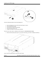
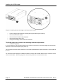
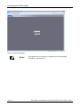
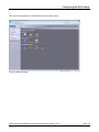
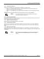
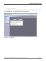
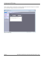
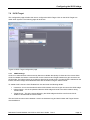
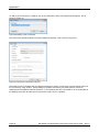
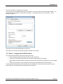
DellTM Model TL24iSCSIxSAS 1Gb iSCSI to SASTM Model TL24iSCSIxSAS 1GBb iSCSI to SAS www.dell.com| support.dell.com Information in this document is subject to change without notice. © 2008 Dell Inc. All rights reserved. Reproduction in any manner whatsoever without the written permission of Dell Inc. is strictly forbidden. Trademarks used in this text: Dell, the DELL logo are trademarks of Dell Inc. Other trademarks and trade names may be used in this document to refer to either the entities claiming the marks and names or their products. Dell inc. disclaims any proprietary interest in trademarks and trade names other than its own. For latest revision of this guide, please go to www.support.dell.com. Model TL24iSCSIxSAS 1Gb iSCSI to SAS Read this first 1. Read this first Contacting Dell Note: If you do not have an active Internet connection, you can find contact information on your purchase invoice, packing slip, bill, or Dell product catalog. Dell provides several online and telephone-based support and service options. Availability varies by country and product, and some service may not be available in your area. To contact Dell for sales, technical support, or customer service issues: 1. Visit http://support.dell.com 2. Verify your country or region in the Choose A Country/Region drop-down menu at the bottom of the page. 3. Click Contact Us on the left side of the page. Note: Toll-free numbers are for use within the country for which they are listed. 4. Select the appropriate service or support link based on your needs. 5. Choose the method of contacting Dell that is convenient for you. Before you start There are a number of additional pieces of equipment you will require for the successful installation of your bridge. Ethernet Cable You will require a good quality cable of suitable length to go between your network access point and the iSCSI bridge. This should be marked as certified to Cat 5e and have a RJ45 style connector at the bridge end. SAS Cable The TL24iSCSIxSAS 1 Gb iSCSI bridge uses a “Mini SAS” style connector, or more commonly known as iPASS connector, with 2 SAS connections per Port. You will require a SAS cable that supports this connector at the bridge end and the type of connect your peripheral device supports at the other. If you are in any doubt, please contact your reseller for assistance. Page 2 Dell Model TL24iSCSIxSAS 1Gb iSCSI to SAS User’s Guide Rev.C Contents 2. Contents 1. Read this first.......................................................................................................................................... 2 2. Contents .................................................................................................................................................. 3 3. Figures..................................................................................................................................................... 5 4. Safety and Environmental Notices ....................................................................................................... 7 5. Preface..................................................................................................................................................... 8 5.1 Product Description ........................................................................................................................... 8 6. Installing the iSCSI bridge ................................................................................................................... 10 6.1 SAS Bus Connections ..................................................................................................................... 15 7. Configuring the iSCSI bridge .............................................................................................................. 17 7.1 Initial set up ...................................................................................................................................... 17 7.2 Network Connections....................................................................................................................... 20 7.2.1 Setting the Hostname .................................................................................................................. 20 7.2.2 Setting up the Gateway ............................................................................................................... 20 7.2.3 Setting up the DNS Server .......................................................................................................... 20 7.2.4 Setting the IP-address ................................................................................................................. 21 7.2.5 Setting the Subnet-Mask ............................................................................................................. 21 7.2.6 Setting the Broadcast-Address .................................................................................................... 21 7.2.7 Committing the changes .............................................................................................................. 21 7.2.8 Reconnect to the bridge............................................................................................................... 21 7.3 Network Ping ................................................................................................................................... 22 7.3.1 Ping a Nework address................................................................................................................ 23 7.4 Setting the Password ....................................................................................................................... 25 7.5 Network Services ............................................................................................................................. 26 7.6 iSCSI Target .................................................................................................................................... 27 7.6.1 CHAP Settings ............................................................................................................................. 27 7.7 Multipath Settings ............................................................................................................................ 28 8. iSCSI Sessions ..................................................................................................................................... 29 8.1 Device Management ........................................................................................................................ 30 8.1.1 Global Settings ............................................................................................................................ 30 8.1.2 Individual Device Info................................................................................................................... 31 9. Maintenance .......................................................................................................................................... 32 9.1 System Information .......................................................................................................................... 32 9.2 System Log ...................................................................................................................................... 33 9.3 Load/Save Configuration ................................................................................................................. 34 9.3.1 Import Configuration .................................................................................................................... 34 9.3.2 Export Configuration .................................................................................................................... 35 9.3.3 Restore Defaults .......................................................................................................................... 35 9.4 Firmware Updates ........................................................................................................................... 36 10. Troubleshooting ................................................................................................................................... 38 10.1 Network Problems ........................................................................................................................... 38 10.2 Device related Problems.................................................................................................................. 38 10.3 Poor Performance ............................................................................................................................ 39 Dell Model TL24iSCSIxSAS 1Gb iSCSI to SAS User’s Guide Rev.C Page 3 Contents 11. Appendix A............................................................................................................................................ 41 11.1 Setting up your computer for initial set up ....................................................................................... 41 12. Appendix B............................................................................................................................................ 43 12.1 Setting up your computer for initial set up ....................................................................................... 43 13. Appendix C............................................................................................................................................ 46 13.1 Connecting to an iSCSI Device using the Microsoft iSCSI Initiator ................................................. 46 13.2 Step 1 – General Set up .................................................................................................................. 46 13.3 Step 2 - Discovery of Devices.......................................................................................................... 47 13.4 Step 3 – Targets .............................................................................................................................. 51 13.5 Step 4 – Viewing iSCSI Session Details.......................................................................................... 55 13.6 Step 5 – Creating multiple connections (Optional) .......................................................................... 56 13.7 Step 6 – Logging off an iSCSI Session ........................................................................................... 61 14. Glossary ................................................................................................................................................ 62 15. Index ...................................................................................................................................................... 64 Page 4 Dell Model TL24iSCSIxSAS 1Gb iSCSI to SAS User’s Guide Rev.C Figures 3. Figures Figure 1 iSCSI Topology.................................................................................................................................... 8 Figure 2 Product view ........................................................................................................................................ 9 Figure 3 Remove the shipping lock ................................................................................................................. 10 Figure 4 Store the label of the library .............................................................................................................. 11 Figure 5 Remove the blank plate..................................................................................................................... 11 Figure 6 Installing the bridge and store the shipping lock ............................................................................... 12 Figure 7 Remove the blank plate on the PowerVault TL4000 ......................................................................... 12 Figure 8 Installing the bridge in the PowerVault TL4000................................................................................. 13 Figure 9 Remove the second blank plate on the PowerVault TL4000 ............................................................ 13 Figure 10 Installing the second bridge in the PowerVault TL4000 .................................................................. 14 Figure 11 Connect the SAS and network cables in the PowerVault TL2000 .................................................. 15 Figure 12 Connect the SAS and network cables in the PowerVault TL4000 .................................................. 16 Figure 13 Login page ....................................................................................................................................... 17 Figure 14 Invalid Login page ........................................................................................................................... 18 Figure 15 Main GUI page ................................................................................................................................ 19 Figure 16 Network configuration page............................................................................................................. 20 Figure 17 Network Ping page .......................................................................................................................... 22 Figure 18 A successful ping ............................................................................................................................ 23 Figure 19 Failed Ping....................................................................................................................................... 24 Figure 20 Network configuration, password page ........................................................................................... 25 Figure 21 Network service page ...................................................................................................................... 26 Figure 22 iSCSI Target configuration page ..................................................................................................... 27 Figure 23 iSCSI Session page ........................................................................................................................ 29 Figure 24 Device Management Page .............................................................................................................. 30 Figure 25 System information page................................................................................................................. 32 Figure 26 System information, log page .......................................................................................................... 33 Figure 27 Saving the configuration page ......................................................................................................... 34 Figure 28 Firmware Update page .................................................................................................................... 36 Figure 29 Firmware update progress page ..................................................................................................... 37 Figure 30 Microsoft iSCSI Initiator general tab ................................................................................................ 46 Figure 31 Entering the Initiator CHAP Secret .................................................................................................. 47 Figure 32 Discovery Tab.................................................................................................................................. 47 Figure 33 Adding a Target portal ..................................................................................................................... 48 Figure 34 Advanced Discovery Settings.......................................................................................................... 48 Figure 35 Adding an iSCSI Target................................................................................................................... 49 Figure 36 Discovery complete ......................................................................................................................... 50 Figure 37 Entering the address of the iSNS-Server ........................................................................................ 50 Figure 38 Targets Tab ..................................................................................................................................... 51 Figure 39 Connecting to an iSCSI Target........................................................................................................ 51 Figure 40 Advanced Connection settings. ....................................................................................................... 52 Figure 41 iSCSI bridge Network Configuration Page ...................................................................................... 53 Figure 42 iSCSI Target Connected ................................................................................................................. 54 Figure 43 iSCSI Session Properties ................................................................................................................ 55 Figure 44 iSCSI Target Device ........................................................................................................................ 56 Dell Model TL24iSCSIxSAS 1Gb iSCSI to SAS User’s Guide Rev.C Page 5 Figures Figure 45 Session Connections Page ............................................................................................................. 56 Figure 46 Adding a new connection ................................................................................................................ 58 Figure 47 Advanced Connections Session...................................................................................................... 58 Figure 48 iSCSI bridge Network Configuration Page ...................................................................................... 59 Figure 49 Showing multiple connections ......................................................................................................... 60 Figure 50 iSCSI Session with Multiple Connections ....................................................................................... 61 Page 6 Dell Model TL24iSCSIxSAS 1Gb iSCSI to SAS User’s Guide Rev.C Safety and Environmental Notices 4. Safety and Environmental Notices When using this product, observe the danger, caution, and attention notices that are contained in this guide. The notices are accompanied by symbols that represent the severity of the safety condition. The sections that follow define each type of safety notice and give examples. DANGER CAUTION High voltage! Risk of electric shock. Do not remove cover (or back). No user-serviceable parts inside. Refer servicing to qualified service personnel. Static sensitive! A discharge of static electricity can damage static-sensitive devices or micro circuitry. Proper packaging and grounding techniques are necessary precautions to prevent damage. Product warranty caution The iSCSI bridge contains no user-serviceable components. Only an Authorized Service Center should carry out any servicing or repairs. Unauthorized repairs or modifications will immediately void your warranty. Dell Model TL24iSCSIxSAS 1Gb iSCSI to SAS User’s Guide Rev.C Page 7 Preface 5. Preface Thank you for purchasing the DELL Model TL24iSCSIxSAS 1Gb iSCSI to SAS bridge. The bridge is designed to ensure connectivity between LTO SAS drives installed in a Dell PowerVault TL24iSCSIxSAS and the network. The bridge has been designed to ensure that the majority of installations will require the minimum of set up before use. However, we suggest you read the following as it will guide you through setting up both the Network and SAS aspects of the iSCSI bridge. The GUI Management section will guide you through the initial set up required to install the bridge on to your network. 5.1 Product Description The iSCSI bridge creates an interface between a network, which utilizes the Ethernet protocol, and peripherals that use a SAS bus architecture. The internal circuitry of the bridge acts as a two-way interface converting the data packets that are received from the network into data transfers and electrical signals that storage devices such as tape drives understand on the SAS bus. Figure 1 iSCSI Topology Page 8 Dell Model TL24iSCSIxSAS 1Gb iSCSI to SAS User’s Guide Rev.C Preface Figure 2 Product view Number Description 1 LED iSCSI bridge ready (Green). Should be blinking when the bridge is ready. 2-5 LED SAS ports 1, 2, 3 and 4 (Green). Should be blinking when there is port activity. 6 Ethernet port. 7 Air vents. 8 Shipping lock (storage location). 9 SAS port. Dell Model TL24iSCSIxSAS 1Gb iSCSI to SAS User’s Guide Rev.C Page 9 Installing the iSCSI bridge 6. Installing the iSCSI bridge Important: Before you undertake any work on the library, switch off the library and remove the AC connector from the library. Important: Hot plugging is not supported, the unit must be powered off for installation of the iSCSI bridge card. There are ten basic steps to install the iSCSI bridge on the Dell PowerVault TL2000: • Remove the blue label that is securing the lock to the blank plate (on the rear panel of the library), and then remove the shipping lock (see Figure 3). Figure 3 Remove the shipping lock • Store the blue label to the top of the library (see Figure 4) and store the shipping lock (see Figure 6). Page 10 Dell Model TL24iSCSIxSAS 1Gb iSCSI to SAS User’s Guide Rev.C Installing the iSCSI bridge Figure 4 Store the label of the library • Remove the blank plate (see Figure 5) on the rear of the library (you need a #3 Phillips screwdriver). Figure 5 Remove the blank plate Important: If your TL2000 library is without card guide rails for the bridge, please install the card guide rails (reference the Getting Started Guide). • Before open the shipping packaging, inspect the box for shipping damage. If you notice any damage, report it to the shipping company. • Unpack carefully the iSCSI board and install it into the library. • It is advisable to retain all your original packaging material in the event you need to ship the bridge. To prevent damage the bridge must be shipped in the original packaging material. • Lock the bridge in place with two Thumb Screws (see Figure 6 steps 1, 2). Dell Model TL24iSCSIxSAS 1Gb iSCSI to SAS User’s Guide Rev.C Page 11 Installing the iSCSI bridge Figure 6 Installing the bridge and store the shipping lock • Store the shipping lock on the iSCSI board (see Figure 6, step 3). • Connect the Ethernet cables. • Connect the SAS cables and peripherals. • Connect the library power cord. • Configure the bridge’s host name and IP-address. There are seven basic steps to installing the iSCSI bridge on the Dell PowerVault TL4000: • Remove the blank plate (see Figure 7) on the rear of the library (you need a #3 Phillips screwdriver). Figure 7 Remove the blank plate on the PowerVault TL4000 Page 12 Dell Model TL24iSCSIxSAS 1Gb iSCSI to SAS User’s Guide Rev.C Installing the iSCSI bridge • Unpack the iSCSI board and install it into the Library (see Figure 8, and Figure 10 step1). Figure 8 Installing the bridge in the PowerVault TL4000 Installing a second bridge in the PowerVault TL4000 with e.g. (four HH SAS Drives). Figure 9 Remove the second blank plate on the PowerVault TL4000 Dell Model TL24iSCSIxSAS 1Gb iSCSI to SAS User’s Guide Rev.C Page 13 Installing the iSCSI bridge Figure 10 Installing the second bridge in the PowerVault TL4000 • Lock the bridge in place with two screws (see Figure 8 and Figure 10 step 2). • Connect the Ethernet cables. • Connect the SAS cables and peripherals. • Connect the library power cord. • Configure the bridge’s host name and IP-address. The iSCSI bridge can be used on the following network configurations: • 1000BaseT (Gigabit) It is not necessary to specify which network type you are connected to as the iSCSI bridge will automatically select the correct network speed upon power up. The connection to the Ethernet network is via an industry standard RJ45 copper interface on the rear plate of the unit. To connect the iSCSI bridge to the Ethernet network, insert the two Cat 5E cables into the connectors on the unit as shown below. When the plugs are in the correct position a “click” should be heard. Page 14 Dell Model TL24iSCSIxSAS 1Gb iSCSI to SAS User’s Guide Rev.C Installing the iSCSI bridge 6.1 SAS Bus Connections The SAS bus on the iSCSI bridge is capable of running at high data transfer speeds, however, devices that operate at slower speeds can still be connected to this SAS bus. In a manner similar to the Ethernet connection, the iSCSI bridge will automatically negotiate with these devices to obtain their optimal operating speed upon power up. Each SAS port will support up to 2 SAS connections. Connect the SAS cable to the rear of the iSCSI bridge as shown below, ensuring that connector is oriented correctly. Figure 11 Connect the SAS and network cables in the PowerVault TL2000 Dell Model TL24iSCSIxSAS 1Gb iSCSI to SAS User’s Guide Rev.C Page 15 Installing the iSCSI bridge Figure 12 Connect the SAS and network cables in the PowerVault TL4000 Page 16 Dell Model TL24iSCSIxSAS 1Gb iSCSI to SAS User’s Guide Rev.C Configuring the iSCSI bridge 7. Configuring the iSCSI bridge Before the iSCSI bridge can be used on the network for the first time, it is necessary to configure a number of IP parameters. To make this as easy as possible, the iSCSI bridge has a Graphical User Interface (GUI) that can be accessed via any web browser. 7.1 Initial set up Connect the iSCSI bridge to the Dell PowerVault drives and the network as described in the previous sections and power up the unit. From your web browser, connect to the iSCSI bridge using the IP-address 10.10.10.10 Depending on how the network parameters are set on the machine you are using to access the iSCSI bridge, it may be necessary to change your network setting on your computer for the initial set up (see Appendix A and B for further help). Once you have connected to the GUI you will see the entry page shown below. Figure 13 Login page Enter the default password – admin. If the password is entered incorrectly, the following screen will be displayed. Dell Model TL24iSCSIxSAS 1Gb iSCSI to SAS User’s Guide Rev.C Page 17 Configuring the iSCSI bridge Figure 14 Invalid Login page Note: Page 18 We suggest that you change your password at the next possible opportunity – see section 7.4 Dell Model TL24iSCSIxSAS 1Gb iSCSI to SAS User’s Guide Rev.C Configuring the iSCSI bridge The GUI will now display the root selection screen as shown below. Figure 15 Main GUI page Dell Model TL24iSCSIxSAS 1Gb iSCSI to SAS User’s Guide Rev.C Page 19 Configuring the iSCSI bridge 7.2 Network Connections Click on the Connections button under the Network section of the main window. This will now bring up a new configuration page. See Figure 16. On this page you can configure the network settings. Figure 16 Network configuration page 7.2.1 Setting the Hostname In this box enter the name you wish to use to address this iSCSI bridge in the future. It is recommended that you use a name that is relevant to its location and or, its purpose. 7.2.2 Setting up the Gateway In this box enter the IP-address of the network gateway. 7.2.3 Setting up the DNS Server A DNS Server allows the iSCSI bridge to communicate with other network clients via their host name. If you have a DNS Server on your network, enter the IP-address in this field. Page 20 Dell Model TL24iSCSIxSAS 1Gb iSCSI to SAS User’s Guide Rev.C Configuring the iSCSI bridge 7.2.4 Setting the IP-address There are two possibilities when configuring the IP-address of the iSCSI bridge: • DHCP - this means the bridge will seek out the DHCP-sever on your network and obtain an IPaddress from the server each time it powers up. • Static IP - the IP-address set in this page will be the IP-address the unit will use each time it powers up. Depending on your configuration, either click the DHCP-button or set your Static IP-address. Note: 7.2.5 If you select the DHCP-mode, ensure your DHCP-server is set to automatically update the DNS-server. Setting the Subnet-Mask If the bridge is configured to use DHCP the net mask will be issued from the DHCP-server. If you are using a static IP-address enter the IP-mask in this box. 7.2.6 Setting the Broadcast-Address Enter in this box your Broadcast-address for your network. 7.2.7 Committing the changes Once you have configured both of the Network-interfaces, click the save button to save these parameters. All changes will only take effect after a reboot. Click the reboot option in the left hand pane to reboot the bridge. 7.2.8 Reconnect to the bridge If you made changes to your computers network settings, for the initial setup, return them to their previous setting and reconnect to the bridge using the IP-address or hostname, depending on which addressing mode you selected. Note: When reconnecting to the bridge the user should flush the arp table in their PC. This can be achieved by typing arp –d from the cmd line window. Dell Model TL24iSCSIxSAS 1Gb iSCSI to SAS User’s Guide Rev.C Page 21 Configuring the iSCSI bridge 7.3 Network Ping From within the Network configuration page on the left hand side the user can access the ping facility. Click on the Network Ping on the left hand side and the user will see the following screen. Figure 17 Network Ping page Ping allows the user to send a data packet over a network which will require a response. This is particularly useful to verify the network connections and that a particular network port is visable. Page 22 Dell Model TL24iSCSIxSAS 1Gb iSCSI to SAS User’s Guide Rev.C Configuring the iSCSI bridge 7.3.1 Ping a Nework address To send a ping packet to a network address, enter the IP-address in the host field and the number of pings to send. By default 5 pings are sent. Click Ping to send the pings. This will take approximately 5 seconds for 5 pings to complete. A successful ping is shown in Figure 18 below. Figure 18 A successful ping Dell Model TL24iSCSIxSAS 1Gb iSCSI to SAS User’s Guide Rev.C Page 23 Configuring the iSCSI bridge When a network address is unreachable, the following display will be seen below in Figure 19. If a network port is unreachable 5 pings can take up to 30 seconds to fail. Figure 19 Failed Ping Page 24 Dell Model TL24iSCSIxSAS 1Gb iSCSI to SAS User’s Guide Rev.C Configuring the iSCSI bridge 7.4 Setting the Password This configuration page will allow the user to change the access password for the GUI. From within the main menu select the Password and Security icon under the Network section. The GUI will now display the following window. Figure 20 Network configuration, password page To change your password, type the existing password and the new password into the appropriate boxes and press Change Password. The password can be a maximum of 16 characters. Important: It is not possible to reset the password without logging into the GUI. Ensure you remember your password! Dell Model TL24iSCSIxSAS 1Gb iSCSI to SAS User’s Guide Rev.C Page 25 Configuring the iSCSI bridge 7.5 Network Services This configuration page will allow the user to configure the IP-addresses for the Network Time Protocol server and the iSNS-service. From within the main menu select the Service Control icon under the Network section. The GUI will now display the following window. Figure 21 Network service page The Network Time Protocol (NTP) is a protocol for synchronizing the clocks of computer systems over the IP network. To enable NTP on the bridge, click the tick box “Use NTP” and enter the IP-address for the NTP Server and then click the save button Internet Storage Name Service (iSNS) allows for the automated discovery, management, and configuration of iSCSI devices from a central point. If this option is enabled the bridge will register its resources with a central iSNS-server. To enable iSNS on the bridge, click the tick box “Use iSNS” and enter the IP-address for the iSNS-Server and click the save button. Page 26 Dell Model TL24iSCSIxSAS 1Gb iSCSI to SAS User’s Guide Rev.C Configuring the iSCSI bridge 7.6 iSCSI Target This configuration page will allow the user to configure the iSCSI Target. Click on the iSCSI Target icon under SCSI Systems. The following page will be shown. Figure 22 iSCSI Target configuration page 7.6.1 CHAP Settings CHAP is an authentication scheme used by Servers to validate the identity of clients and vice versa. When CHAP is enabled, the initiator must send the correct Username and Target Password to gain access to the iSCSI bridge. The Initiator Secret is provided to allow iSCSI mutual CHAP. If mutual CHAP is selected on the Initiator, the iSCSI bridge will authenticate itself with the initiator using the initiator secret. To enable CHAP click the ‘CHAP Enabled’ tick box and enter the following details: • Username – this is the username that the iSCSI Initiator must use to gain access to the iSCSI bridge • Initiator Secret – this is the password that the iSCSI bridge will send to the iSCSI Initiator during mutual CHAP • Target Secret – This is the secret defined by the iSCSI bridge and will be sent from the ISCSI Initiator to authenticate the iSCSI Initiator. The two CHAP secrets must be between 12 and 16 characters long and both Initiator and Target Secrets must be different. Dell Model TL24iSCSIxSAS 1Gb iSCSI to SAS User’s Guide Rev.C Page 27 Configuring the iSCSI bridge 7.7 Multipath Settings Multipath is a method of sending data to an iSCSI target over multiple network connections. These network connections can be on the same physical network cable or separate network cables. This increases the data bandwidth to send data over. A user may have a single iSCSI Session for an iSCSI Target, but within that session may have multiple connections. iSCSI uses two main network ports, 3260 and 860. Within the Multipath configuration the user can specify which ports will be made available, 860, 3260 or both. By default, the bridge will allow up to 10 iSCSI connections per iSCSI Session. However, some initiators will only allow 1 iSCSI Connection per iSCSI Session and will reject any login to an iSCSI Target that tries to negotiate more iSCSI Connections. If this is the case, click the compatibility check box and this will limit the number of connections to 1. Page 28 Dell Model TL24iSCSIxSAS 1Gb iSCSI to SAS User’s Guide Rev.C iSCSI Sessions 8. iSCSI Sessions This page displays the current iSCSI Sessions i.e. iSCSI hosts logged on to the bridge . It displays which initiator is connected to which Target device. Figure 23 shows a number of iSCSI Session currently logged in to an iSCSI Target. Figure 23 iSCSI Session page Note: It is possible that more than one Initiators to be connected to any target device or one Initiator to multiple target devices. It is possible to send a logout request to an initiator by highlighting the initiator’s session and pressing the logout button. This will logout an iSCSI Session and all iSCSI Connections associated with that ISCSI session. Note: Many initiators are configured to automatically reconnect after completing the logout request. If this is the case then the connections window may not show any change. Dell Model TL24iSCSIxSAS 1Gb iSCSI to SAS User’s Guide Rev.C Page 29 iSCSI Sessions 8.1 Device Management This configuration page will allow the user to configure a number of parameters that control the behavior of the devices connected to the SAS Bus. From within the main menu select the Device Management section. The GUI will now display the following window. Figure 24 Device Management Page 8.1.1 Global Settings The first option ‘Persistent LUN by Device’s:’ allows the user to select whether SAS Devices are identified by its WWN or SCSI ID for persistency. For this product the mapping option is restricted to Multiple Targets with Single LUN – this will present all SAS devices, whether they are LUNs of a SAS device or not, to appear as an individual IQNs on the iSCSI interface. Page 30 Dell Model TL24iSCSIxSAS 1Gb iSCSI to SAS User’s Guide Rev.C iSCSI Sessions 8.1.2 Individual Device Info By clicking on the blue triangle in the Device info box you can display further information about each SAS device. The expanded information also gives you two further options. Persistent LUN - if you select this option, the device will always be presented to the iSCSI interface in exactly the same way – i.e. the same IQN. If the device is disabled or has been removed from the SAS port the IQN will be reserved and will not be assigned to any other SAS device. Enabled – This pull down menu option allows you to disable a SAS device from appearing on the iSCSI interface. This is useful if you wish to reserve a device or to take it out of commission for repair or replacement at a later date without powering down the bridge. IQN - iSCSI Qualified Name iSCSI naming convention that uniquely identifies every device. An IQN is up to 255 characters long. LUN - Logical Unit Number - A LUN is a number which identifies a sub-element within a SCSI target device. This is normally used to refer to the device itself. Dell Model TL24iSCSIxSAS 1Gb iSCSI to SAS User’s Guide Rev.C Page 31 Maintenance 9. Maintenance The following section describes the various pages that are available to the user to monitor the performance, review the error log, import/export a configuration and update the iSCSI bridge’s firmware. 9.1 System Information This System information page will allow the user to view the performance of the iSCSI bridge. From within the main menu, select the System Information icon from the bridge maintenance section. The GUI will now display the following window Figure 25 System information page Within the top window the following information is displayed: • Current Firmware Level. • Serial Number of the PCB within the bridge. • iSCSI IQN – Each iSCSI device has a unique identifier – this entry shows the IQN for the bridge. Within System Performance there are 2 bar graphs which provide an approximation of the following performance parameters: • Network Speed - This indicates the current performance in MB/s across the network. • CPU - This indicates the percentage of the time the CPU is occupied undertaking the management and scheduling the transfer of data between the two interfaces. Page 32 Dell Model TL24iSCSIxSAS 1Gb iSCSI to SAS User’s Guide Rev.C Maintenance 9.2 System Log This system information page will allow the user to view the log status that the bridge encounters while running. From within the main menu select the View Log-file icon from the bridge maintenance section. The GUI will now display the following window. Figure 26 System information, log page If the user wishes to save the log file to his local disk, click on ‘Click Here to Download’. A popup message will be displayed where the user can specify a meaningful file name and location to save the system log. After setting the file name and path, select save. Dell Model TL24iSCSIxSAS 1Gb iSCSI to SAS User’s Guide Rev.C Page 33 Maintenance 9.3 Load/Save Configuration The Load Save Configuration page will allow the user to save the configuration parameters to a local disk partition and load from it. From within the main menu select the Load Save Configuration icon from the bridge maintenance section. The GUI will now display the following window. Figure 27 Saving the configuration page 9.3.1 Import Configuration If the user wishes to load previously saved configuration file, select ’Browse’ from within the ’Import Configuration’ box, locate the *.bin file that was previously saved, then click ’Upload’ button. The system settings will now be set. Note: Page 34 Some of the settings uploaded during this operation may require the bridge to be rebooted to take effect. Dell Model TL24iSCSIxSAS 1Gb iSCSI to SAS User’s Guide Rev.C Maintenance 9.3.2 Export Configuration Once you have finished configuring your bridge we recommend that you save your configuration data to a local disk. By doing so, you could save valuable time if the unit requires replacement or if a configuration is lost during upgrades. To save the configuration data click on the “Click here to Download” link from within the Export Configuration window located in the centre of the page. Depending upon the browser you are using, select the option to save file to disk. The bridge will now download an encoded file that contains all the configuration settings for the bridge. Note: 9.3.3 It is also possible to creating a “Boiler Plate” configuration and loading this into each new bridge as it is initialised. This can ease the rollout of multiple bridges within an enterprise. Restore Defaults By clicking on this button all the parameters will be set back to the factory defaults. This includes IP-address, hostname and passwords. Note: We strongly recommend that if you return the bridge for maintenance that you reset to defaults to protect passwords and other sensitive information. Dell Model TL24iSCSIxSAS 1Gb iSCSI to SAS User’s Guide Rev.C Page 35 Maintenance 9.4 Firmware Updates The Firmware Updates page will allow the user to load new firmware into the bridge. From within the main menu select the Firmware Updates icon from the bridge maintenance section. The GUI will now display the following window. Figure 28 Firmware Update page Page 36 Dell Model TL24iSCSIxSAS 1Gb iSCSI to SAS User’s Guide Rev.C Maintenance From time to time it may be necessary to upgrade the firmware within the bridge. New versions contain resolutions to known issues as well as new features and improvements to the functionality of the bridge. It is advisable to check for the latest release on a regular basis. New version of the firmware can be downloaded from the Dell web site at: www.dell.com/support. Once you have downloaded the new firmware to a local disk drive: • Click on the browse button to locate the file you have downloaded from the website. • Then click on the update button. During the update progress of the update can be displayed. This is shown in Figure 29 below. Figure 29 Firmware update progress page If for some reason the update was not successful or the user wishes to restart the update process, the user can click on the ‘Restart Firmware Update’ button after the current update has completed. Once the update has been completed the iSCSI bridge will require a reboot for the new firmware to take effect. Dell Model TL24iSCSIxSAS 1Gb iSCSI to SAS User’s Guide Rev.C Page 37 Troubleshooting 10. Troubleshooting 10.1 Network Problems The iSCSI bridge is not visible on the Network. Under normal operation you should be able to “ping” the network address of the bridge and receive a response. If this fails, run through the following check list to help you identify the problem. • Ensure that the bridge is properly plugged into the library and that the library is powered on. Make sure that the power LED on the bridge is illuminated. • Ensure that the Ethernet cable is plugged in at both ends. • Note the status of the LEDs positioned within the Ethernet connector – make sure that the “Link present” LED is illuminated - If not, check with your Network Administrator. • If you are using a bridge with two Ethernet ports and only one network cable, try using the other network address and/or the other network port. • Ensure you are using the correct network address and subnet-mask. • Scan the network using a LAN-Scan utility (available via internet) to find all the bridges connected to the network in case the network address is different from the expected. • If none of the above resolves your problem, then after consulting your Network Administrator, please contact support. 10.2 Device related Problems The iSCSI bridge is visible on the Network but no devices appear on the host machine. Once the bridge has booted and the target devices have finished initializing, these devices should be available on the host machine. After checking that you have correctly configured the iSCSI initiator, run through the following checklist to help you identify the problem. • Ensure that the library and the tape devices are powered on and ready – some libraries can take 5 minutes or more before they are ready and appear on the bridge. (The power up status of libraries is usually displayed on the front panel). • Ensure that the cable between the bridge and the tape drives in the library are connected. • Connect to the bridge via the GUI interface and check that devices are present in the Device management window and are enabled – you will need to drill down each device entry to see this option. Page 38 Dell Model TL24iSCSIxSAS 1Gb iSCSI to SAS User’s Guide Rev.C Troubleshooting Note: • If you can “ping” the bridge but the GUI interface fails to appear check the setting within the Web Browser you are using. If you are directly connected to the bridge then any proxy setting will require adjustment and may require you to contact your administrator. Ensure that the CHAP settings for the initiator and the bridge are the same. Note: A common mistake is to enable CHAP only for a device after the initial discovery by the initiator. It will be necessary to remove the address from the discoveries tab and recreate it with the appropriate CHAP settings, otherwise any rediscoveries will be attempted without CHAP and no devices will be returned. • Force a rediscovery from the initiator. • Reboot the library and bridge. • If none of the above resolves your problem, please contact support. 10.3 Poor Performance • Poor performance can be caused by many different reasons. The following checklist is provided as a guide to where you may find ways to improve performance. • Ensure your initiator and bridge are communicating at the fastest possible network speed. Within the GUI interface in the Network Connections window, select this and check the Link Speed entry in each of the Link Status Box. This should be 1000Mb/s - if this is 10 or 100Mb/s this will limit the performance dramatically. • Packet loss can be a cause of poor performance. Within the Link Status Box check the number of TX and RX errors for both network interfaces. This should be zero or, a very small number. If these are showing a large number of errors, check the connections between the bridge and the initiator. Also check that the entire network cabling between the initiator and the bridge is Cat5e certified. • By enabling Jumbo packets (increasing the MTU size to 9000 from within the GUI Network Connections window) you can improve the throughput performance of the bridge. This will only work if ALL of the components in the infrastructure between the Initiator and the bridge are enabled for Jumbo packets. That includes the HBA, all switches and routers and the bridge itself. If any of the components are not enabled or not capable of handling Jumbo packets then unexplainable packet loss or corruption can happen. • Data Digests are an extra level of checksum error checking on top of the standard TCP/IP checksum error checking (configured on the initiator). However, the calculation of these extra checksum can greatly effect the overall performance. Therefore, Header and Data Digests should only be enabled where the integrity of the Network connection is in doubt. • It is possible to configure the bridge so that the data from the initiator is balanced across both network connections. Ensure that you have connected and configured them in accordance to Appendix C and not by enabling the Multipath connection option in the Windows initiator login screen. You should also check the routing tables in your switches, routers and initiator to ensure both IP-addresses are not routed down on Network link at any stage. Also, add the following registry settings: From the start menu within windows, select run, then type regedit. In the folder: HKEY_LOCAL_MACHINE\SYSTEM\CurrentControlSet\Services\Tcpip\Parameters\ Dell Model TL24iSCSIxSAS 1Gb iSCSI to SAS User’s Guide Rev.C Page 39 Troubleshooting Add the following DWORD settings: GlobalMaxTcpWindowSize = 0x01400000 TcpWindowSize = 0x01400000 Tcp1323Opts = 3 SackOpts = 1 Note: • If you are unsure about editing you system registry settings contact your system administrator as changing the system registry settings can damage your system. Poor GUI performance. If the bridge is transferring large amounts of data then the response from the GUI may seem a little slow as the process that controls the GUI has the lowest priority for Network and CPU resources. Page 40 Dell Model TL24iSCSIxSAS 1Gb iSCSI to SAS User’s Guide Rev.C Appendix A 11. Appendix A 11.1 Setting up your computer for initial set up If your computer is running Windows 95, 98 or NT follow the instructions below. For users with Windows 2000, 2003, XP, 2008 instructions are detailed in Appendix B. In the Network window’s Configuration tab, Select the TCP/IP entry. Then the Properties Button. Dell Model TL24iSCSIxSAS 1Gb iSCSI to SAS User’s Guide Rev.C Page 41 Appendix A Click on the IP-address tab. Make a Note of your current set up then: Click on the Specify an IP-address button. Enter 10.10.10.11into the IP-address field. Enter 255.255.255.0 into the Subnet-Mask field. Finally click the OK button and reboot your computer. Note: Page 42 Once you have completed the initial set up of the iSCSI bridge, return your computer to the original settings and reconnect to the iSCSI bridge. Dell Model TL24iSCSIxSAS 1Gb iSCSI to SAS User’s Guide Rev.C Appendix B 12. Appendix B 12.1 Setting up your computer for initial set up If your computer is running Windows 2000, 2003, XP or 2008 follow the instructions below. For users with Windows 95, 98 or NT instructions are detailed in Appendix A. From the Desk Top or Start menu, select My Computer. In the My Computer window select Network and Dial-up Connections positioned in the bottom left hand corner. Dell Model TL24iSCSIxSAS 1Gb iSCSI to SAS User’s Guide Rev.C Page 43 Appendix B From within the displayed Network and Dial-up Connections select the interface connection that will be used to connect to the iSCSI bridge – in this example we have selected the Gigabit Ethernet interface. A general status page will be displayed. From within this page select Properties. Page 44 Dell Model TL24iSCSIxSAS 1Gb iSCSI to SAS User’s Guide Rev.C Appendix B Select the Internet Protocol (TCP/IP) entry and then Properties. Make a Note of your current set up then: Click Use the following IP-address. Enter 10.10.10.11 into the IP-address field. Enter 255.255.255.0 into the Subnet-Mask field. Finally click the OK button. Note: Once you have completed the initial set up of the iSCSI bridge, return your computer to the original settings and reconnect to the iSCSI bridge. Dell Model TL24iSCSIxSAS 1Gb iSCSI to SAS User’s Guide Rev.C Page 45 Appendix C 13. Appendix C 13.1 Connecting to an iSCSI Device using the Microsoft iSCSI Initiator There are many iSCSI Initiators available. However, for the purpose of this user guide we shall concentrate only on the Microsoft iSCSI Initiator. In this example we have used the Microsoft iSCSI that is available with Microsoft Vista. However, the following procedure should be identical for all versions of Microsoft iSCSI Initiator. 13.2 Step 1 – General Set up Open the iSCSI initiator and then click on the General Tab. You should see a window as shown in Figure 30. Figure 30 Microsoft iSCSI Initiator general tab In this window the user is able to configure the initiator name, specify the initiator secret and set up the IPsec connections. For the purpose of this document we shall leave the initiator name as the default. The iSCSI bridge not support this. Page 46 Dell Model TL24iSCSIxSAS 1Gb iSCSI to SAS User’s Guide Rev.C Appendix C If you intend to use Mutual CHAP authentication you must enter the Initiator secret on this page. Click on the secret button and a window should be displayed as in Figure 31. Figure 31 Entering the Initiator CHAP Secret Enter in the Initiator Secret and click OK. The secret should be between 12 and 16 characters. Make a note of this secret as you will need to enter this as part of configuring CHAPon the iSCSI bridge 13.3 Step 2 - Discovery of Devices Before the user can connect to an iSCSI Target, the iSCSI targets must be discovered. Click on the Discovery tab and you should see a window as in Figure 32. Figure 32 Discovery Tab Dell Model TL24iSCSIxSAS 1Gb iSCSI to SAS User’s Guide Rev.C Page 47 Appendix C To add an iSCSI Target portal, click on ‘Add Portal’. The user should now be presented with a window as in Figure 33. Figure 33 Adding a Target portal Enter an IP-address for the iSCSI Target. In this example we shall use the IP-address of 10.10.10.50. Leave the port 3260 unless you have configured your iSCSI bridge only to respond on port 860, in which case change it to 860. Click on the advanced button to see the advanced options. This is shown in Figure 34. Figure 34 Advanced Discovery Settings The ‘Connect by using‘ box allows the user to specify which iSCSI Adaptor to use and the Source IP. The Local adaptor will only differ from Microsoft iSCSI Initiator setting if an iSCSI Offload card has been installed. For the purpose of this guide we shall only use the Microsoft iSCSI Initiator. Leaving this setting as Default will also use the Microsoft iSCSI Initiator. The Source IP is used to specify upon which network adaptor the discovery will be done. In most cases the user will want to leave this as default. If multiple network interfaces are installed in the Server and the user wishes to select a particular interface, select the IP-address of that network interface from the pull down list. Page 48 Dell Model TL24iSCSIxSAS 1Gb iSCSI to SAS User’s Guide Rev.C Appendix C CRC/Checksum settings allow the user to specify whether the discovery is done using Data and/or Header Digests. Unless the iSCSI device is on a poor quality network where data corruption is likely, it is recommended then Header and Data Digests are left disabled, as performance will be affected. If the iSCSI bridge has had CHAP enabled, or the user wishes to authenticate the iSCSI bridge, click on the checkbox ‘CHAP login information’ to enable CHAP. Now enter the username and target secret that was configured on the iSCSI bridge. If the user wishes to authenticate the iSCSI bridge, select ‘Perform mutual authentication’. Note: For mutual CHAP to be performed, the Initiator Secret must be set on the general tab, and be the same as the one configured on the iSCSI bridge. The use of RADUS is beyond the scope of this guide. Once the user is satisfied that all advanced options are correct click OK. The user should now see a window as in Figure 35. Figure 35 Adding an iSCSI Target Dell Model TL24iSCSIxSAS 1Gb iSCSI to SAS User’s Guide Rev.C Page 49 Appendix C Now click OK and the Microsoft iSCSI Initiator shall perform the discovery. This usually performs quickly but can take up to a minute with multiple network ports. Once the discovery is complete, the user should see the target listed in the Target Portals list. See Figure 36. Figure 36 Discovery complete If the user has an iSNS-server then the address can be added in the iSNS-servers list by clicking Add. A window should appear as seen in Figure 37. Figure 37 Entering the address of the iSNS-Server Enter the address of the iSNS-Server then click OK. The Microsoft iSCSI-Initiator will now query the iSNSServer and discover any iSCSI-Targets that are registered. Page 50 Dell Model TL24iSCSIxSAS 1Gb iSCSI to SAS User’s Guide Rev.C Appendix C 13.4 Step 3 – Targets Click on the Targets tab. The devices discovered should now be listed and shown in Figure 38. Figure 38 Targets Tab In this example two iSCSI targets have been discovered. The first device is the tape drive, and the second is the media changer. If no devices are displayed, check the settings used to do the discovery, especially the CHAP settings then return to Targets tab and click Refresh. If still no devices are displayed, check network cables and that the iSCSI bridge is operational. To connect to one of the iSCSI Targets, click on one of the target names and then click the ‘Log on’ button. In this example we have chosen the first target. A window should appear as in Figure 39. Figure 39 Connecting to an iSCSI Target Dell Model TL24iSCSIxSAS 1Gb iSCSI to SAS User’s Guide Rev.C Page 51 Appendix C If the user wishes to connect to the target automatically when the computer is booted, click the check box ‘Automatically restore this connection when the computer starts’. Even if the user wishes to connect to the iSCSI Target using Multipath, they should not check ‘Enable Multipath’ Check box. This will be covered in a following section. Now click on the advanced button to see the advanced settings. A window should appear as in Figure 40. Figure 40 Advanced Connection settings. Page 52 Dell Model TL24iSCSIxSAS 1Gb iSCSI to SAS User’s Guide Rev.C Appendix C This advanced settings page is the same as that of the discovery with one addition. On the ‘Connect by using’ section the user can select the Target Port that he wishes to connect too. This is particularly useful if the user is going to create multiple connections. In this example we have chosen to connect to the IPaddress 10.10.10.50 on port 3260. To see how this relates to the iSCSI bridge configuration note the IP-addresses in Figure 41. Figure 41 iSCSI bridge Network Configuration Page Dell Model TL24iSCSIxSAS 1Gb iSCSI to SAS User’s Guide Rev.C Page 53 Appendix C Set up the Digest and CHAP settings as described in stage 2 during the discovery phase and click OK. This will now take you back to the window that was shown in figure 10. Click OK once more. The user should now see the iSCSI Target connected. This is shown in Figure 42. Figure 42 iSCSI Target Connected Page 54 Dell Model TL24iSCSIxSAS 1Gb iSCSI to SAS User’s Guide Rev.C Appendix C 13.5 Step 4 – Viewing iSCSI Session Details Now that the user has connected to an iSCSI Target, to check that the device is connected click on the Details button. A window should appear as in Figure 43. Figure 43 iSCSI Session Properties In this window the user can view the iSCSI Sessions associated to the iSCSI Target, how many connections are attached to each iSCSI Session, and the Target Portal Group. If the user clicks on the Device tab, he should see details of the target device. Here we can see that the device is an IBM LTO Tape drive. Dell Model TL24iSCSIxSAS 1Gb iSCSI to SAS User’s Guide Rev.C Page 55 Appendix C Figure 44 iSCSI Target Device 13.6 Step 5 – Creating multiple connections (Optional) If the user wishes to create multiple connections to an iSCSI Session, return to the Session tab in the Target Properties window. Click on the Connections button and a window should appear. This is shown in Figure 45. Figure 45 Session Connections Page Page 56 Dell Model TL24iSCSIxSAS 1Gb iSCSI to SAS User’s Guide Rev.C Appendix C The Session Connections window shows how many iSCSI Connections are active and the type of load balance used. For all iSCSI Sessions there will be at least one ‘leading connection’. iSCSI connections can be added and removed at any time, all apart from the leading connection, which can only be removed when the iSCSI Session is logged off. The Load balance policy specifies how the data is distributed over multiple connections. The main policies that should be used are ‘Round Robin’ and ‘Fail Over Only’. Round Robin will utilize all connections for data and evenly distribute the data. Fail Over Only will use the Leading connection for data transfer. If a connection should go down then the data transfer shall switch on one of the other connections. For most purposes Round Robin will provide the greatest performance increase. If you have been experiencing a performance decrease when transferring data to more than one device using multiple connections, please refer to the trouble shooting guide. Dell Model TL24iSCSIxSAS 1Gb iSCSI to SAS User’s Guide Rev.C Page 57 Appendix C To add a new connection to a session, click on the Add button and a new window should appear. This is shown in Figure 46. Figure 46 Adding a new connection Now click on the Advanced button to see the Advanced Settings. This is shown in Figure 47. Figure 47 Advanced Connections Session Select the Source IP-address and the Target Portal that you wish to connect too via the pull down menus in the “Connect by using” section. When setting up multiple connections you ideally want to connect to different ports and different network interfaces. In this example we have connected to 10.10.10.50/3260 as the leading connection and the second connection will be 10.10.11.50/3260. Page 58 Dell Model TL24iSCSIxSAS 1Gb iSCSI to SAS User’s Guide Rev.C Appendix C The corresponding network configuration on the iSCSI bridge for the example above is shown below in Figure 48. Figure 48 iSCSI bridge Network Configuration Page Dell Model TL24iSCSIxSAS 1Gb iSCSI to SAS User’s Guide Rev.C Page 59 Appendix C Set up CHAP and Digest then click OK. The user will now be brought back to the window shown in Figure 46. Click OK and now the user should see the Session Connections page with two connections. This is shown in Figure 49. Figure 49 Showing multiple connections Page 60 Dell Model TL24iSCSIxSAS 1Gb iSCSI to SAS User’s Guide Rev.C Appendix C The user can add up to 8 different connections. Once the user has completed setting up the connections, click OK to return to the iSCSI session page. You should now see the number of connections increased. In this example we have 2 connections. This is shown in Figure 50. Figure 50 iSCSI Session with Multiple Connections Now click on OK to return to the Microsoft iSCSI Initiator main window. 13.7 Step 6 – Logging off an iSCSI Session To log off an iSCSI Session, follow the following procedure. • Open the Microsoft iSCSI Initiator and click on the Targets tab. • Click on the iSCSI session that the user wishes to log off and then click Details. • In the Target Properties window, select the Sessions Tab and select the identifier that is to be logged off. • Click the Log off button. This will log off all connections associated with the iSCSI Session. The session identifier should now be removed from the identifier list. Click ok to return to the main iSCSI Initiator window. The iSCSI device should now show as inactive. Dell Model TL24iSCSIxSAS 1Gb iSCSI to SAS User’s Guide Rev.C Page 61 Glossary 14. Glossary Broadcast-address - a type of networking address reserved for sending messages to all machines on a given network segment. Bridge - a hardware device to connect two topologies together. CAT5E - Category 5 Ethernet network cabling enhanced - A standard of network cabling to allow data transmission of speeds up to 1000 Mbs (giga-bit Ethernet). CHAP - Challenge Handshake Authentication Protocol - An authentication technique for confirming the identity of one computer to another. Described in RFC 1994. CID - Connection Identifier - an initiator generated 16-bit number presented during the login phase which uniquely identifies a connection between two iSCSI devices. CPU - An abbreviation of central processing unit. The CPU is the brain of the computer. Data Digest - a code used to insure data integrity of data blocks. Checksums and CRCs are common types of digests. Ethernet - IEEE 802.3 standard for LANs (local area networks) allowing multiple computers to connect on the same network using IP as the communication protocol. Firmware - proprietary code that is usually delivered as microcode as part of an operating system. Firmware is more efficient than software loaded from an alterable medium and more adaptable to change than pure hardware circuitry. An example of firmware is the Basic Input/Output System (BIOS) in read-only memory (ROM) on a PC motherboard. Gigabit Ethernet - Ethernet technology that transmits data at speeds up to 1 Gigabit per second (Gbps). GUI - Graphical User Interface - graphical user interface using icons and a pointer for operations. IP-address - an identifier for a computer or device on a TCP/IP network. Networks using the TCP/IP protocol route messages based on the IP-address of the destination. The format of an IP-address is a 32-bit numeric address written as four numbers separated by periods. Each number can be zero to 255. For example, 1.160.10.240 could be an IP-address. IPS - Internet Protocol Storage – IP-protocol classes or devices which use IP-protocol to move data in a storage network. iSCSI is an example of IPS protocols. IQN - iSCSI Qualified Name iSCSI naming convention that uniquely identifies every device. An IQN is up to 255 characters long. iSCSI - Internet Small Computer Systems Interface A protocol to transport SCSI commands on IP networks. This allows data storage devices to be linked together over IP-networks. iSNS - allows automated discovery, management, and configuration of iSCSI from a central point. LAN - Local area network. A computer network within a limited area. Page 62 Dell Model TL24iSCSIxSAS 1Gb iSCSI to SAS User’s Guide Rev.C Glossary LED - Light-emitting diode. LUN - Logical Unit Number - A LUN is a number which identifies a sub-element within a SCSI target device. This is normally used to refer to the device itself. NTP - Network Time Protocol is a protocol for synchronizing the clocks of computer systems over the IP network. NTP as defined in IETF RFC 1305 is useful for synchronizing the internal clock of the computers to a common time source. RJ45 - A commonly used connector for networks. Serial Attached SCSI (SAS) - SAS is a performance improvement over traditional SCSI because SAS enables multiple devices (up to 128) of different sizes and types to be connected simultaneously with thinner and longer cables; its full-duplex signal transmission supports 3.0 Gb/s. In addition, SAS drives can be hotplugged. Subnet-address - the subnet-address is an extension of the IP-address allowing a single IP-network address to be used for multiple physical networks. Gateways and hosts using subnet-addressing divide the host portion of the address into a subnet-identifier and host portion. Switch - a network communications device that routes packets (messages or fragments of messages) between nodes across virtual circuits. TCP/IP - Transmission Control Protocol/Internet Protocol. TCP is a protocol that insures packets are delivered in order, error free. Dell Model TL24iSCSIxSAS 1Gb iSCSI to SAS User’s Guide Rev.C Page 63 Index 15. Index B Broadcast Address 21 L C Login 17 Configuring 12, 14, 17 Connecting 12, 14 Connections 15, 20 M G N GUI interface 17, 19, 25 Network 8, 20, 25, 26, 32 H P Hostname 20 Password 25, 27 Product view 9 Maintenance 32, 33, 34, 36 I Information 2, 32 Initial set up 17 IP Address 21 iSCSI 2, 7, 8, 10, 11, 12, 13, 14, 15, 17, 20, 21, 26, 27, 29, 31, 32, 42, 45, 62 iSCSI Bridge 2, 7, 8, 10, 12, 14, 15, 17, 20, 21, 42, 45 Page 64 S SAS Bus 15 Service 7, 26 Shipping lock 9 Subnet Mask 21 System Log 33 Dell Model TL24iSCSIxSAS 1Gb iSCSI to SAS User’s Guide Rev.C