1
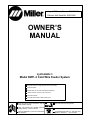
August 2000 Form: OM-179 078 Effective With Serial No. KG041900 OWNER’S MANUAL cyclomatic Model DWF–3 Cold Wire Feeder System Automatic Control For Supplying Filler Wire Into The Weld GTAW And PAW Stepper Motor For Accurate, Repeatable Feed Rates 120/240 Volts AC Input Power To Control Unit Overload Protection Automatic Wire Retract At End Of Weld Cycle Read and follow these instructions and all safety blocks carefully. cover 5/94 Give this manual to the operator. Have only trained and qualified persons install, operate, or service this unit. For help, call your distributor Call your distributor if you do not understand the directions. or: MILLER Electric Mfg. Co., P.O. Box 1079, Appleton, WI 54912 414-734-9821 1996 MILLER Electric Mfg. Co. PRINTED IN USA From Miller to You Thank you and congratulations on choosing Miller. Now you can get the job done and get it done right. We know you don’t have time to do it any other way. That’s why when Niels Miller first started building arc welders in 1929, he made sure his products offered long-lasting value and superior quality. Like you, his customers couldn’t afford anything less. Miller products had to be more than the best they could be. They had to be the best you could buy. Today, the people that build and sell Miller products continue the tradition. They’re just as committed to providing equipment and service that meets the high standards of quality and value established in 1929. This Owner’s Manual is designed to help you get the most out of your Miller products. Please take time to read the Safety precautions. They will help you protect yourself against potential hazards on the worksite. We’ve made installation and operation quick and easy. With Miller you can count on years of reliable service with proper maintenance. And if for some reason the unit needs repair, there’s a Troubleshooting section that will help you Miller is the first welding figure out what the problem is. The parts list equipment manufacturer in will then help you to decide which exact part the U.S.A. to be registered to the ISO 9001 Quality System you may need to fix the problem. Warranty and Standard. service information for your particular model are also provided. Miller Electric manufactures a full line of welders and welding related equipment. For information on other quality Miller products, contact your local Miller distributor to receive the latest full line catalog or individual catalog sheets. To locate your nearest distributor or service agency call 1-800-4-A-Miller, or visit us at www.MillerWelds.com on the web. Working as hard as you do – every power source from Miller is backed by the most hassle-free warranty in the business. Miller offers a Technical Manual which provides more detailed service and parts information for your unit. To obtain a Technical Manual, contact your local distributor. Your distributor can also supply you with Welding Process Manuals such as SMAW, GTAW, GMAW, and GMAW-P. ARC WELDING SAFETY PRECAUTIONS WARNING ARC WELDING can be hazardous. PROTECT YOURSELF AND OTHERS FROM POSSIBLE SERIOUS INJURY OR DEATH. KEEP CHILDREN AWAY. PACEMAKER WEARERS KEEP AWAY UNTIL CONSULTING YOUR DOCTOR. In welding, as in most jobs, exposure to certain hazards occurs. Welding is safe when precautions are taken. The safety information given below is only a summary of the more complete safety information that will be found in the Safety Standards listed on the next page. Read and follow all Safety Standards. HAVE ALL INSTALLATION, OPERATION, MAINTENANCE, AND REPAIR WORK PERFORMED ONLY BY QUALIFIED PEOPLE. in disconnect box or that cord plug is connected to a properly grounded receptacle outlet. ELECTRIC SHOCK can kill. Touching live electrical parts can cause fatal shocks or severe burns. The electrode and work circuit is electrically live whenever the output is on. The input power circuit and machine internal circuits are also live when power is on. In semiautomatic or automatic wire welding, the wire, wire reel, drive roll housing, and all metal parts touching the welding wire are electrically live. Incorrectly installed or improperly grounded equipment is a hazard. 1. Do not touch live electrical parts. 2. Wear dry, hole-free insulating gloves and body protection. 3. Insulate yourself from work and ground using dry insulating mats or covers big enough to prevent any physical contact with the work or ground. 4. Disconnect input power or stop engine before installing or servicing this equipment. Lockout/tagout input power according to OSHA 29 CFR 1910.147 (see Safety Standards). 5. Properly install and ground this equipment according to its Owner’s Manual and national, state, and local codes. 6. Always verify the supply ground – check and be sure that input power cord ground wire is properly connected to ground terminal ARC RAYS can burn eyes and skin; NOISE can damage hearing; FLYING SLAG OR SPARKS can injure eyes. Arc rays from the welding process produce intense visible and invisible (ultraviolet and infrared) rays that can burn eyes and skin. Noise from some processes can damage hearing. Chipping, grinding, and welds cooling throw off pieces of metal or slag. NOISE 1. Use approved ear plugs or ear muffs if noise level is high. FUMES AND GASES can be hazardous to your health. Welding produces fumes and gases. Breathing these fumes and gases can be hazardous to your health. 1. Keep your head out of the fumes. Do not breathe the fumes. 2. If inside, ventilate the area and/or use exhaust at the arc to remove welding fumes and gases. 3. If ventilation is poor, use an approved air-supplied respirator. 4. Read the Material Safety Data Sheets (MSDSs) and the manufacturer’s instruction for metals, consumables, coatings, cleaners, and degreasers. CYLINDERS can explode if damaged. Shielding gas cylinders contain gas under high pressure. If damaged, a cylinder can explode. Since gas cylinders are normally part of the welding process, be sure to treat them carefully. 1. Protect compressed gas cylinders from excessive heat, mechanical shocks, slag, open flames, sparks, and arcs. 2. Install cylinders in an upright position by securing to a stationary support or cylinder rack to prevent falling or tipping. 3. Keep cylinders away from any welding or other electrical circuits. 7. When making input connections, attach proper grounding conductor first – double-check connections. 8. Frequently inspect input power cord for damage or bare wiring – replace cord immediately if damaged – bare wiring can kill. 9. Turn off all equipment when not in use. 10. Do not use worn, damaged, undersized, or poorly spliced cables. 11. Do not drape cables over your body. 12. If earth grounding of the workpiece is required, ground it directly with a separate cable – do not use work clamp or work cable. 13. Do not touch electrode if you are in contact with the work, ground, or another electrode from a different machine. 14. Use only well-maintained equipment. Repair or replace damaged parts at once. Maintain unit according to manual. 15. Wear a safety harness if working above floor level. 16. Keep all panels and covers securely in place. 17. Clamp work cable with good metal-to-metal contact to workpiece or worktable as near the weld as practical. ARC RAYS 2. Wear a welding helmet fitted with a proper shade of filter to protect your face and eyes when welding or watching (see ANSI Z49.1 and Z87.1 listed in Safety Standards). 3. Wear approved safety glasses with side shields. 4. Use protective screens or barriers to protect others from flash and glare; warn others not to watch the arc. 5. Wear protective clothing made from durable, flame-resistant material (wool and leather) and foot protection. 5. Work in a confined space only if it is well ventilated, or while wearing an air-supplied respirator. Always have a trained watchperson nearby. Welding fumes and gases can displace air and lower the oxygen level causing injury or death. Be sure the breathing air is safe. 6. Do not weld in locations near degreasing, cleaning, or spraying operations. The heat and rays of the arc can react with vapors to form highly toxic and irritating gases. 7. Do not weld on coated metals, such as galvanized, lead, or cadmium plated steel, unless the coating is removed from the weld area, the area is well ventilated, and if necessary, while wearing an air-supplied respirator. The coatings and any metals containing these elements can give off toxic fumes if welded. 4. 5. 6. 7. Never drape a welding torch over a gas cylinder. Never allow a welding electrode to touch any cylinder. Never weld on a pressurized cylinder – explosion will result. Use only correct shielding gas cylinders, regulators, hoses, and fittings designed for the specific application; maintain them and associated parts in good condition. 8. Turn face away from valve outlet when opening cylinder valve. 9. Keep protective cap in place over valve except when cylinder is in use or connected for use. 10. Read and follow instructions on compressed gas cylinders, associated equipment, and CGA publication P-1 listed in Safety Standards. sr1.1.1 2/94 WELDING can cause fire or explosion. Welding on closed containers, such as tanks, drums, or pipes, can cause them to blow up. Sparks can fly off from the welding arc. The flying sparks, hot workpiece, and hot equipment can cause fires and burns. Accidental contact of electrode to metal objects can cause sparks, explosion, overheating, or fire. Check and be sure the area is safe before doing any welding. 1. Protect yourself and others from flying sparks and hot metal. 2. Do not weld where flying sparks can strike flammable material. 3. Remove all flammables within 35 ft (10.7 m) of the welding arc. If this is not possible, tightly cover them with approved covers. 4. Be alert that welding sparks and hot materials from welding can easily go through small cracks and openings to adjacent areas. 5. Watch for fire, and keep a fire extinguisher nearby. WARNING 6. Be aware that welding on a ceiling, floor, bulkhead, or partition can cause fire on the hidden side. 7. Do not weld on closed containers such as tanks, drums, or pipes, unless they are properly prepared according to AWS F4.1 (see Safety Standards). 8. Connect work cable to the work as close to the welding area as practical to prevent welding current from traveling long, possibly unknown paths and causing electric shock and fire hazards. 9. Do not use welder to thaw frozen pipes. 10. Remove stick electrode from holder or cut off welding wire at contact tip when not in use. 11. Wear oil-free protective garments such as leather gloves, heavy shirt, cuffless trousers, high shoes, and a cap. 12. Remove any combustibles, such as a butane lighter or matches, from your person before doing any welding. ENGINES can be hazardous. ENGINE EXHAUST GASES can kill. 1. Use equipment outside in open, well-ventilated areas. Engines produce harmful exhaust gases. 2. If used in a closed area, vent engine exhaust outside and away from any building air intakes. ENGINE FUEL can cause fire or explosion. 3. Do not overfill tank – allow room for fuel to expand. 4. Do not spill fuel. If fuel is spilled, clean up before starting engine. Engine fuel is highly flammable. 1. Stop engine and let it cool off before checking or adding fuel. 2. Do not add fuel while smoking or if unit is near any sparks or open flames. MOVING PARTS can cause injury. Moving parts, such as fans, rotors, and belts can cut fingers and hands and catch loose clothing. 1. Keep all doors, panels, covers, and guards closed and securely in place. 2. Stop engine before installing or connecting unit. SPARKS can cause BATTERY GASES TO EXPLODE; BATTERY ACID can burn eyes and skin. Batteries contain acid and generate explosive gases. STEAM AND PRESSURIZED HOT COOLANT can burn face, eyes, and skin. It is best to check coolant level when engine is cold to avoid scalding. 3. Have only qualified people remove guards or covers for maintenance and troubleshooting as necessary. 4. To prevent accidental starting during servicing, disconnect negative (–) battery cable from battery. 5. Keep hands, hair, loose clothing, and tools away from moving parts. 6. Reinstall panels or guards and close doors when servicing is finished and before starting engine. 1. Always wear a face shield when working on a battery. 2. Stop engine before disconnecting or connecting battery cables. 3. Do not allow tools to cause sparks when working on a battery. 4. Do not use welder to charge batteries or jump start vehicles. 5. Observe correct polarity (+ and –) on batteries. 1. If the engine is warm and checking is needed, follow steps 2 and 3. 2. Wear safety glasses and gloves and put a rag over cap. 3. Turn cap slightly and let pressure escape slowly before completely removing cap. PRINCIPAL SAFETY STANDARDS Safety in Welding and Cutting, ANSI Standard Z49.1, from American Welding Society, 550 N.W. LeJeune Rd, Miami FL 33126 Safety and Health Standards, OSHA 29 CFR 1910, from Superintendent of Documents, U.S. Government Printing Office, Washington, D.C. 20402. Recommended Safe Practices for the Preparation for Welding and Cutting of Containers That Have Held Hazardous Substances, American Welding Society Standard AWS F4.1, from American Welding Society, 550 N.W. LeJeune Rd, Miami, FL 33126 National Electrical Code, NFPA Standard 70, from National Fire Protection Association, Batterymarch Park, Quincy, MA 02269. sr1.1.1 2/94 Safe Handling of Compressed Gases in Cylinders, CGA Pamphlet P-1, from Compressed Gas Association, 1235 Jefferson Davis Highway, Suite 501, Arlington, VA 22202. Code for Safety in Welding and Cutting, CSA Standard W117.2, from Canadian Standards Association, Standards Sales, 178 Rexdale Boulevard, Rexdale, Ontario, Canada M9W 1R3. Safe Practices For Occupation And Educational Eye And Face Protection, ANSI Standard Z87.1, from American National Standards Institute, 1430 Broadway, New York, NY 10018. Cutting And Welding Processes, NFPA Standard 51B, from National Fire Protection Association, Batterymarch Park, Quincy, MA 02269. ! IMPORTANT ! THIS MANUAL HAS BEEN DESIGNED FOR EXPERIENCED WELDING EQUIPMENT OPERATORS AND MUST BE READ COMPLETELY BEFORE USING THIS EQUIPMENT. IF YOU LACK EXPERIENCE OR ARE UNFAMILIAR WITH THE PRACTICES AND SAFE OPERATION OF WELDING EQUIPMENT, PLEASE CONSULT YOUR FOREMAN. DO NOT ATTEMPT TO INSTALL, OPERATE, OR PERFORM MAINTENANCE ON THIS EQUIPMENT UNLESS YOU ARE QUALIFIED AND HAVE READ AND UNDERSTAND THIS MANUAL. IF IN DOUBT ABOUT INSTALLING OR OPERATING THIS EQUIPMENT, CONTACT YOUR DISTRIBUTOR OR THE CUSTOMER SERVICE DEPARTMENT. DEFINITIONS NOTE CAUTION WARNING DANGER Throughout this manual, NOTE, CAUTION, WARNING and DANGER are inserted to call attention to particular information. The methods used to identity these highlights and the purpose for which each is used, are as follows: NOTE OPERATIONAL, PROCEDURAL, AND BACKGROUND INFORMATION WHICH AIDS THE OPERATOR IN THE USE OF THE MACHINE, HELPS THE SERVICEMAN IN THE PERFORMANCE OF MAINTENANCE, AND PREVENTS DAMAGE TO THE EQUIPMENT. CAUTION AN OPERATIONAL PROCEDURE WHICH, IF NOT FOLLOWED, MAY CAUSE MINOR INJURY TO THE OPERATOR, SERVICE PERSONNEL AND/OR BYSTANDERS. WARNING AN OPERATIONAL PROCEDURE WHICH, IF NOT FOLLOWED, MAY CAUSE SEVERE INJURY TO THE OPERATOR, SERVICE PERSONNEL, OR OTHERS IN THE OPERATING AREA. DANGER AN OPERATIONAL PROCEDURE WHICH, IF NOT FOLLOWED, WILL CAUSE SEVERE INJURY OR EVEN DEATH TO THE OPERATOR, SERVICE PERSONNEL OR BYSTANDERS. EMF INFORMATION NOTE Considerations About Welding And The Effects Of Low Frequency Electric And Magnetic Fields The following is a quotation from the General Conclusions Section of the U.S. Congress, Office of Technology Assessment, Biological Effects of Power Frequency Electric & Magnetic Fields – Background Paper, OTA-BP-E-53 (Washington, DC: U.S. Government Printing Office, May 1989): “. . . there is now a very large volume of scientific findings based on experiments at the cellular level and from studies with animals and people which clearly establish that low frequency magnetic fields can interact with, and produce changes in, biological systems. While most of this work is of very high quality, the results are complex. Current scientific understanding does not yet allow us to interpret the evidence in a single coherent framework. Even more frustrating, it does not yet allow us to draw definite conclusions about questions of possible risk or to offer clear science-based advice on strategies to minimize or avoid potential risks.” To reduce magnetic fields in the workplace, use the following procedures: 1. Keep cables close together by twisting or taping them. 2. Arrange cables to one side and away from the operator. 3. Do not coil or drape cables around the body. 4. Keep welding power source and cables as far away as practical. 5. Connect work clamp to workpiece as close to the weld as possible. About Pacemakers: The above procedures are among those also normally recommended for pacemaker wearers. Consult your doctor for complete information. mod10.1 4/93 TABLE OF CONTENTS DESCRIPTION 1.1 1.2 1.3 1.4 INTRODUCTION . . . . . . . . . . . . . . . . . . . . . . . . . . . . . . . . . . . . . . . . . . . . . . . . . . . . . . . . . . . . . . . CONTROL UNIT . . . . . . . . . . . . . . . . . . . . . . . . . . . . . . . . . . . . . . . . . . . . . . . . . . . . . . . . . . . . . . . WIRE DRIVE UNIT . . . . . . . . . . . . . . . . . . . . . . . . . . . . . . . . . . . . . . . . . . . . . . . . . . . . . . . . . . . . . WIRE GUIDE ASSEMBLY . . . . . . . . . . . . . . . . . . . . . . . . . . . . . . . . . . . . . . . . . . . . . . . . . . . . . . . 1-1 1-1 1-1 1-1 INSTALLATION 2.1 2.2 2.3 2.4 2.5 2.6 2.7 GENERAL SET–UP . . . . . . . . . . . . . . . . . . . . . . . . . . . . . . . . . . . . . . . . . . . . . . . . . . . . . . . . . . . . CONTROL UNIT LOCATION . . . . . . . . . . . . . . . . . . . . . . . . . . . . . . . . . . . . . . . . . . . . . . . . . . . . WIRE DRIVE UNIT MOUNTING . . . . . . . . . . . . . . . . . . . . . . . . . . . . . . . . . . . . . . . . . . . . . . . . . WIRE GUIDE MOUNTING . . . . . . . . . . . . . . . . . . . . . . . . . . . . . . . . . . . . . . . . . . . . . . . . . . . . . . CONDUIT LENGTH ADJUSTMENT . . . . . . . . . . . . . . . . . . . . . . . . . . . . . . . . . . . . . . . . . . . . . . REMOTE CONTROLS . . . . . . . . . . . . . . . . . . . . . . . . . . . . . . . . . . . . . . . . . . . . . . . . . . . . . . . . . . CHANGING RETRACT DISTANCE . . . . . . . . . . . . . . . . . . . . . . . . . . . . . . . . . . . . . . . . . . . . . . . 2-1 2-1 2-1 2-4 2-6 2-8 2-8 OPERATION 3.1 3.2 3.3 3.4 PRECAUTIONS . . . . . . . . . . . . . . . . . . . . . . . . . . . . . . . . . . . . . . . . . . . . . . . . . . . . . . . . . . . . . . . . CONTROL DESCRIPTION – DWF–3 . . . . . . . . . . . . . . . . . . . . . . . . . . . . . . . . . . . . . . . . . . . . . SEQUENCE OF OPERATION . . . . . . . . . . . . . . . . . . . . . . . . . . . . . . . . . . . . . . . . . . . . . . . . . . . REMOTE SIGNALS . . . . . . . . . . . . . . . . . . . . . . . . . . . . . . . . . . . . . . . . . . . . . . . . . . . . . . . . . . . . 3-1 3-1 3-2 3-3 MAINTENANCE AND REPAIR 4.1 4.2 4.3 4.4 4.5 MAINTENANCE REQUIREMENTS . . . . . . . . . . . . . . . . . . . . . . . . . . . . . . . . . . . . . . . . . . . . . . . GENERAL PRECAUTIONS . . . . . . . . . . . . . . . . . . . . . . . . . . . . . . . . . . . . . . . . . . . . . . . . . . . . . CONTROL UNIT CALIBRATION . . . . . . . . . . . . . . . . . . . . . . . . . . . . . . . . . . . . . . . . . . . . . . . . . DRIVE UNIT ASSEMBLY . . . . . . . . . . . . . . . . . . . . . . . . . . . . . . . . . . . . . . . . . . . . . . . . . . . . . . . TROUBLESHOOTING . . . . . . . . . . . . . . . . . . . . . . . . . . . . . . . . . . . . . . . . . . . . . . . . . . . . . . . . . . 4-1 4-1 4-1 4-3 4-3 CIRCUIT DESCRIPTION 5.1 5.2 5.3 5.4 SPEED CONTROL CIRCUITS . . . . . . . . . . . . . . . . . . . . . . . . . . . . . . . . . . . . . . . . . . . . . . . . . . . DELAY TIMER CIRCUITS . . . . . . . . . . . . . . . . . . . . . . . . . . . . . . . . . . . . . . . . . . . . . . . . . . . . . . . DIGITAL DISPLAY CIRCUIT . . . . . . . . . . . . . . . . . . . . . . . . . . . . . . . . . . . . . . . . . . . . . . . . . . . . . MOTOR POWER SUPPLY CIRCUIT . . . . . . . . . . . . . . . . . . . . . . . . . . . . . . . . . . . . . . . . . . . . . 5-1 5-1 5-1 5-1 SECTION 1 1.1 DESCRIPTION INTRODUCTION Cold wire feed systems are designed for accurate application of filler wire into the weld or braze area. The DWF–3 is designed to be used for GTAW and PAW processes. The Digital Wire Feeder System is made up of a positive feeding wire drive with a zero backlash 3–axis wire manipulator. This combination of components produces exceptionally good wire feeding characteristics. Systems will accommodate wire sizes from .020 in diameter (.50 mm) to .094 in diameter (2.39 mm) and feed at an adjustable rate, continuously variable from 0 to 300 inches per minute. A standard DWF–3 system is shown in Figure 1.1. 1.2 CONTROL UNIT The control unit uses solid state circuitry in its motor supply and control circuits and operates from a 115/230 VAC, 50/60 Hz line supply. Provisions have been made for forward or reverse jog to allow easy pre–positioning of the filler wire. Start of wire feed and control of speed may be accomplished both manually from the front panel or remotely through the interface connector located on the rear panel. The speed at which the wire will feed is pre–set through use of the ”PUSH TO SET” function on the front panel and can be controlled within 0.10 inch per minute increments. A digital readout of wire speed is provided. Start delay and stop delay timers are also provided for cycle control. Timers can be pre–set within 0.10 second intervals from 0 to 9.9 seconds. 1.3 WIRE DRIVE UNIT The wire drive unit uses urethane rollers to grip the wire and feed it in either direction depending on the signals from the control unit. These rollers eliminate the need to change rollers when changing wire sizes from .020 in (.50 mm) diameter through .062 in (1.57 mm) diameter wire. Special rollers are required for .094 in (2.39 mm) diameter wire. All wire can be loaded into the drive while it is operating. There is no need to hand–feed the wire through the mechanism before operating. Inlet and exit guides are provided with the wire drive. One inlet guide covers the entire range of wire sizes from .020 in diameter (.50 mm) to .094 in (2.39 mm) diameter. Three exit guides cover the range of wire diameters. Two of the exit guides are for the .020 in through .062 in range. The third is for the .094 in wire. The guides are stored inside the drive housing. If a drive for .020 in – .062 in wire is ordered, then two exit and one inlet guide will be supplied. If a drive for .094 in wire is ordered, then one exit and one inlet guide will be supplied. 1.4 WIRE GUIDE ASSEMBLY The wire guide assembly which is used with the DWF–3 wire drive unit consists of a guide mechanism, conduit, liners, and tip. The guide mechanism is constructed to allow full position adjustment for vertical, cross seam, feed angle and distance from the electrode. Tips and liners can be changed to suit the wire size being used (see information listed in Table 1.1) Standard length of the conduit supplied with the system is 36 in (914.4 mm). The length may be shortened by following steps 2.5A through 2.5D in the installation section. TABLE 1.1 WIRE GUIDE DETAILS WIRE SIZE ROLLER EXIT GUIDE LINER GUIDE TIP .020 in (.50 mm) 179 170 179 173 179 184 – .030 in (.76 mm) 179 170 179 173 179 184 – .035 in (.89 mm) 179 170 179 173 179 184 – .045 in (1.1 mm) 179 170 179 173 179 184 – .062 in (1.5 mm) 179 170 – 179 185 – OM-179 078 1-1 SECTION 1 DESCRIPTION You may also order a combination of the wire guide mechanism, tip, conduit assembly, and conduit liner together as follows: .020 – .062 in dia. 179 165* *This includes all tips necessary for operation of .020 – .062 in dia. wire in one package. Figure 1.1, DIGITAL WIRE FEED SYSTEM OM-179 078 1-2 SECTION 2 2.1 INSTALLATION GENERAL SET–UP A standard DWF–3 system is illustrated in Figure 2.1 with the necessary interconnections shown for a typical installation. The parts are listed below: DWF–3 (.020 – .062) CONTROL UNIT 179 166 WIRE DRIVE UNIT 179 164 WIRE GUIDE ASSEMBLY 179 165 2.2 CONTROL UNIT LOCATION The control unit should be placed in a location which provides easy access to the controls and proper air ventilation for cooling. Adequate ventilation is provided by maintaining a minimum of 5 in (127 mm) of unrestricted space between the control unit sides and rear and the nearest obstruction. The location should be selected to minimize any dust, dirt, moisture or corrosive vapors the control unit could be subjected to. Control unit outline dimensions are given in Figure 2.2. CAUTION THE CONTROL UNIT CAN OPERATE ON EITHER 100/120 VOLTS OR 208/230 VOLTS AC, 50 OR 60 HZ. BE SURE TO SELECT THE PROPER INPUT VOLTAGE ON THE REAR PANEL BEFORE CONNECTING TO POWER. 2.3 WIRE DRIVE UNIT MOUNTING Figure 2.3 is an outline and a mounting dimension guide. The drive unit may be mounted using the inlet guide surface or the bottom surface (opposite the adjusting knob) through use of the existing tapped holes in the housing. The wire drive exit guide has a 7/16 – 20 UNF external thread for mating with the supplied wire guide conduit for a DWF–3 system. CAUTION IN APPLICATIONS WHERE HIGH FREQUENCY OR CAPACITIVE DISCHARGE START IS USED THE DRIVE HOUSING SHOULD BE GROUNDED TO THE SAME POTENTIAL AS THE WORKPIECE. THIS WILL PREVENT POSSIBLE DAMAGE TO THE WIRE FEED DRIVE,CAUSED BY ARCING. GROUNDING CAN BE ACCOMPLISHED THROUGH THE UNUSED THREADED MOUNTING HOLES IN THE DRIVE HOUSING. OM-179 078 2-1 SECTION 2 INSTALLATION Figure 2.1, DIGITAL WIRE FEED INSTALLATION OM-179 078 2-2 SECTION 2 INSTALLATION Figure 2.2, CONTROL UNIT OUTLINE OM-179 078 2-3 SECTION 2 INSTALLATION Figure 2.3, DRIVE UNIT OUTLINE 2.4 WIRE GUIDE MOUNTING The guide mechanism portion of the wire guide assembly is made to accommodate a standard 1–3/8 in (34.9 mm) diameter machine torch barrel (see Figure 2.4). Guide tips are available for specific wire sizes from .020 in to .094 in diameter. The conduit, with proper liner is attached to both the wire drive exit guide and the wire guide mechanism (see Table 1.1 for proper selection of these parts). Sharp bends in the conduit must be avoided. If shorter conduit lengths are required, see Section 2.5. OM-179 078 2-4 SECTION 2 INSTALLATION Figure 2.4, WIRE GUIDE ASSEMBLY TABLE 2.1 WIRE GUIDE ASSEMBLY ITEM QTY PART NMBR 1 1 – BODY MANIPULATOR MACHINED 2 1 – PIVOT–WIRE MANIPULATOR 3 1 – KNOB, VERT. ADJ–WIRE MANIPULATOR 4 1 – CLAMP, WIRE MANIPULATOR 5 1 – RACK–WIRE MANIPULATOR 6 1 – CLAMP, TORCH 7 1 – COUPLING, MANIPULATOR TWECO 8 1 – SCREW, THUMB 10–32 ST STEEL 9 1 – SCREW, THUMB 10 1 – FITTING MODIFIED 11 1 – HOSE, FLEX–TEFLON LINED 12 1 179 177 TIP, WIRE GUIDE .020 13 1 179 178 TIP, WIRE GUIDE .035 14 1 179 179 TIP, WIRE GUIDE .045 15 1 179 180 TIP, WIRE GUIDE .062 16 1 179 181 TIP, WIRE GUIDE .030 17 1 179 182 TIP, WIRE GUIDE .052 18 1 – TIP, WIRE GUIDE .094 19 A/R 179 184 LINER, CONDUIT 20 A/R 179 185 LINER, CONDUIT OM-179 078 DESCRIPTION 2-5 SECTION 2 2.5 INSTALLATION CONDUIT LENGTH ADJUSTMENT The conduit as supplied is an assembled unit 36 in (914 mm) long. If shorter lengths are desired, the conduit may be cut and reassembled according to the following steps. A) Disassemble existing fitting on one end. Save the fitting components. Wrap hose with masking tape at cut–off point and cut square to length through taped area using a sharp cut–off wheel or a fine–tooth hack saw. Remove tape and trim any loose wires flush with tube stock. Any burrs on the bore of the tube stock should be removed with a knife. Clean the hose bore. The wire braid will tend to ”neck down” on this end. This is characteristic of wire braid hose and can be used to advantage in the assembly of the fittings. Slip the socket over the ”necked down” end of the hose, positioned approximately 3 in (76 mm) from the end. Mount nipple hex in a vise. Work the hose bore over the nipple to size the tube and aid in separating the braid prior to fitting the sleeve. Remove hose from nipple. B) Push the sleeve over the end of the tube and under the wire braid by hand. Complete positioning of the sleeve by pushing the hose end against a flat surface. Visually inspect to see that tube stock butts against the inside shoulder of the sleeve. Set the sleeve barbs into the Teflon tube by pushing the assembly tool or a round nose tapered punch into the end of the sleeve and tube. OM-179 078 2-6 SECTION 2 INSTALLATION C) Lubricate nipple and socket threads. For stainless steel fittings, use a molydisulfide base lubricant (e.g., Molykote Type G); lubricants containing chloride are not recommended. Other material combinations use standard petroleum lubricants. Hold the nipple with hex in vise. Push hose over nipple with twisting motion until seated against nipple chamfer. Push socket forward, and hand start threading of socket to nipple. D) Wrench tighten nipple hex until clearance with socket hex is 1/32 in or less. Tighten further to align corners of nipple and socket hexes. Clean and inspect all assemblies. After the conduit is prepared, the liner may be cut to length and installed as shown in Figure 2.4 and explained in Section 2.4. TABLE 2.2 DIGITAL WIRE FEED REMOTE SIGNALS SIGNAL REMARKS Remote Start/Stop 5–24 VDC, or contact closure signal to start Inhibit 5–24 VDC, or contact closure signal to inhibit wire feed without stopping weld cycle FWD/REV JOG Contact closure signal to drive wire forward or reverse Remote Speed Control 10K potentiometer or 0–1.235 volt signal for 0–300 ipm Start Delay On 24 VDC lamp, or relay drive during start delay Auto Feed 24 VDC lamp, or relay drive during automatic cycle wire feed Motor Pulse 24 VDC low level signal pulse 1 pulse 0.0116 inches of wire travel. OM-179 078 2-7 SECTION 2 2.6 INSTALLATION REMOTE CONTROLS A number of remote capabilities are available with the DWF–3 system. On the rear panel of the control unit a connector is provided for remote operation. The remote connector, in addition to providing for the remote control connections, provides the user access to other wire feeder signals. This may be used to incorporate the DWF–3 into a complete welding package system. The signals available are listed in Figure 3.3 and are described in more detail in Section 3.4. The factory also provides an optional prewired connector and shielded cable for connection to these signals. (See Sections 3.4). 2.7 CHANGING RETRACT DISTANCE The wire retract distance which occurs at the end of a wire feed cycle comes preset from the factory at 0.512 inches. This distance can be changed thru the range of 0.085 inches to 1.28 inches by changing the ”E” jumpers. (See Table 4.3). OM-179 078 2-8 SECTION 3 3.1 OPERATION PRECAUTIONS Verify the following before connecting power to control unit. 1. Make certain the drive unit is grounded. 2. Check that all connections are secure and properly installed. All connections should be made to the torch and power supply before applying power to the control unit. 3. Should the cover of the control unit be removed for any reason, be sure the AC line cord is disconnected. 4. Check line voltage selector switch on rear panel for proper input voltage being used. CAUTION THE CONTROL UNIT CAN OPERATE ON EITHER 100/120 VOLTS OR 208/230 VOLTS AC, 50 OR 60 HZ. BE SURE TO SELECT THE PROPER INPUT VOLTAGE ON THE REAR PANEL BEFORE CONNECTING TO POWER. 3.2 CONTROL DESCRIPTION – DWF–3 Refer to Figure 3.1 for location of the following front panel controls. ON–OFF: Switches primary line voltage to the control unit. When power is ON, the power indicator will be illuminated. MANUAL START – OFF – REMOTE START: In the center OFF position, a wire feed cannot be initiated; in the up MANUAL START position, a wire feed cycle is started. If this switch is placed down, in the REMOTE START position, a wire feed cycle can be initiated by applying an external signal to the proper pins of the remote connector on the rear panel. (See Section 3.4 for complete details on REMOTE START.) The feed cycle stops for the DWF–3 system when either the REMOTE START (if used) or the MANUAL START switch is placed in the OFF position. REVERSE – FORWARD JOG: Pressing the Jog Switch down, to the FORWARD position, will cause wire to feed out of the wire drive unit at the rate of 102.4 inches per min (2601 mm/min); this speed is factory set and cannot be changed. Pressing the Jog Switch up, to the REVERSE position, will cause wire to be pulled back into the wire drive unit – also at 102.4 inches per min (2601 mm/min). Releasing the switch will cause it to return to the center OFF position. In this way wire can be pre–positioned for the weld cycle. Figure 3.1, DWF–3 FRONT PANEL OM-179 078 3-1 SECTION 3 OPERATION Figure 3.2, DWF–3 REAR PANEL START DELAY: Allows for a delay between the time a weld cycle is initiated and the time when wire feeding begins; START DELAY is presettable in 0.1 second increments, from 0.0 to 9.9 seconds. STOP DELAY: Allows for a delay between the time when a weld cycle is terminated and the time when wire retracts then stops feeding. STOP DELAY allows for crater fill and is variable from 0 to 9.9 seconds in 0.1 sec– intervals. WIRE SPEED: Digital display that indicates WIRE SPEED in inches per minute, in 0.1 inch per minute increments. PUSH TO SET: Used in conjunction with the SPEED control to preset wire feed rate. Pressing this switch while rotating the speed control allows the operator to preset the wire feed rate without actually feeding wire, thereby eliminating waste of filler wire. SPEED CONTROL: When in the STANDARD position, wire speed is controlled by the SPEED potentiometer located directly under the digital display on the control panel. When in the REMOTE position, wire speed is controlled by a REMOTE signal. 3.3 SEQUENCE OF OPERATION After the DWF–3 has been installed, make sure all cables and connectors are properly mated. Check the line voltage selector switch on the rear panel to ensure it is set at the proper position to match the line voltage being used. The MANUAL/REMOTE switch should be in the OFF position. Back off thumbscrew on the drive unit to allow introduction of wire between drive rolls. Turn the power switch ON. The POWER indicator should illuminate and the digital display should read all zeros. Adjust thumbscrew to provide contact on wire. Activate the FORWARD Jog Switch and “guide” the filler wire into the wire drive entrance guide. The rollers will ”pick up” the wire and begin feeding. Continue feeding the wire FORWARD until the wire is in position at the end of the guide tip. Use JOG FORWARD/REVERSE to adjust position. Select the desired amount of START DELAY by setting the thumbwheel switches to the appropriate value. Do the same for STOP DELAY or FEED TIME as applicable. Next, select the WIRE SPEED by pressing the PUSH TO SET button. While holding this button in, rotate the SPEED knob until the desired WIRE SPEED is OM-179 078 3-2 SECTION 3 OPERATION indicated on the digital display; set the SPEED CONTROL selector switch to the STANDARD position. Positioning the MANUAL START/REMOTE START switch to the MANUAL START position will now initiate a wire feed cycle. The digital display will blink during START DELAY time. At the end of START DELAY, wire will begin to feed and the speed will be indicated on the display. Re–setting the MANUAL START switch to OFF will initiate the end of a wire feed cycle for the DWF–3. After STOP DELAY times out, the motor on the wire drive unit will reverse and retract the filler wire from the weld puddle; after the retract time, wire will stop feeding and the cycle is complete. 3.4 REMOTE SIGNALS The DWF–3 control unit has the capability of being controlled from a remote location. Seven signals are available as described in Table 2.2 as well as the following paragraphs. Electrical connections are made as shown in Figures 3.3, 3.4 and 3.5. A prewired connector and cable is available from the factory (P/N 179 167) . REMOTE START is implemented by applying a signal between pin C and F. Pin C is the positive terminal and pin F is the negative terminal. This signal should be 5–24 VDC. The cycle will remain active as long as the signal is applied. The cycle terminates when the signal is removed. The INHIBIT FUNCTION is implemented by applying a signal to pins E and G; pin E is positive and pin G is negative. This signal should be 5–24 VDC. When the inhibit signal is applied, the wire feed is interrupted, but the cycle is not affected at its point in the cycle. When the inhibit signal is removed, the wire feed will continue. This feature is helpful for manual override or a pulse synchronization of wire to a pulsing power source. REMOTE JOG FORWARD/REVERSE is implemented by the use of a SPDT switch. The center pole is connected to pin D. The forward pole is connected to pin L and the reverse pole is connected to pin K. This switch is now wired in parallel with the Jog switch on the front panel, and functions in the same manner. REMOTE WIRE SPEED control is implemented in much the same way. A 10K 1/2W potentiometer is connected with its wiper (center pole) on pin N. The plus reference voltage pole is connected to pin M and the minus or ground pole is connected to pin A. This pot is now selected by switching the speed control switch on the front panel (lower right corner of wire speed area) to the REMOTE position. Wire speed is now determined by setting this pot. The wire speed may also be controlled by a 0 to 1.235 volt signal (pin N to pin A which corresponds to 0 to 300 inch per minute wire speed). REMOTE START DELAY signal is an output that signals when the system is in the DELAY timing mode. When the START DELAY times out, the signal is removed. This signal is 24 VDC 500 mA max current. It may be used to light a remote indicator lamp or energize a relay coil. The signal connects to pin I of the remote connector; return is ground (pin D). REMOTE AUTO FEED signal is an output that signals when the system is feeding wire automatically at the selected rate. Its output characteristics are the same as the remote start delay signal. The signal is on pin J at the remote connector; return is ground (pin D). MOTOR PULSE signal is an output that signals each step of the feed motor. This signal is a 24V, 18 sec wide pulse with a 10K source resistance. It may be used for a tachometer output of wire length output. Each pulse represents 0.0116 inches of wire feed. The signal is on pin H; return is ground (pin D). OM-179 078 3-3 SECTION 3 OPERATION Figure 3.3, REMOTE WIRING CABLE The remote start function requires a signal of +5 to 24 VDC. This signal is applied to pin C of J3. The common is from the DWF–3 (this signal is optically isolated from the DWF–3); therefore, the signal common need not be attached to the control unit ground. This signal would normally come through the normally open contacts of a relay that is activated at the start of a weld cycle, for example, the Seam Tracker interface relay. The inhibit function requires a signal of +5 to 24 VDC applied to pin E of J3, and common connected to pin G of J3. The inhibit signals are optically isolated from the DWF–3 control unit, and the common need not be connected to the control unit ground. Figure 3.4, REMOTE START WIRING OM-179 078 3-4 SECTION 3 OPERATION Figure 3.5, INHIBIT FUNCTION WIRING OM-179 078 3-5 SECTION 4 4.1 MAINTENANCE AND REPAIR MAINTENANCE REQUIREMENTS The DWF–3 wire feed system has no special scheduled maintenance requirements. However, periodic inspection of control and wire drive are helpful in preventing equipment failures. Replace any worn or broken parts found. Periodic dust and oil removal from both the control and drive is recommended. 4.2 GENERAL PRECAUTIONS Figure 4.1 shows a control unit for the DWF–3 system. Assemblies and parts which are authorized for user replacement are listed in Table 4.1. Should the user experience a problem and determine the defective part (see TROUBLESHOOTING, Section 4.5), the suggested repair procedure is to remove and replace the defective part. CAUTION WHEN INSPECTING OR REPAIRING THE CONTROL UNIT ASSEMBLY, DISCONNECT AC POWER FROM THE UNIT BEFORE REMOVING THE COVER TO PREVENT ELECTRICAL SHOCK. 4.3 CONTROL UNIT CALIBRATION The control unit has been calibrated and fully tested before leaving the factory. It is unlikely that it would require adjustment; however, if the need for recalibration arises, there are three adjustments that can be made that affect wire speed and delay time accuracy. The only test equipment required is a good quality frequency counter of known accuracy. Two adjustments, R2 and R7 on Controller/Driver circuit board affect wire speed accuracy. Perform the following steps to calibrate the control unit. A) Connect the frequency counter to TP14. B) Rotate the speed control knob on the front panel to its minimum speed setting, i.e., fully counterclockwise. C) Adjust R7 until the frequency counter indicates zero. D) Repeat Steps B and C. There is only one adjustment to be made on the time base osc. – R10; it sets the start and stop delay accuracy and the wire speed readout accuracy. E) Connect the frequency counter to TP2, and adjust R10 for a reading of 2560 Hz ± 1 Hz. NOTE: REPEAT STEPS B THROUGH E IF THE ADJUSTMENT ON R10 IS CHANGED. TABLE 4.1 PARTS LIST FOR CONTROL UNIT ITEM QTY PART NMBR 1 1 179 186 CHASSIS ASSEMBLY 2 1 179 188 PWB DWF–3 CONTROLLER/DRIVER 3 1 179 189 PWB DWF–3 DISPLAY AND DRIVER 4 1 – TRANSFORMER ASSY, DWF–3 5 1 – ASSY, THUMBWHEEL SWITCH 6 1 – ASSY, THUMBWHEEL SWITCH 7 1 – CABLE ASSY, DWF–3 INTERNAL INTERFACE OM-179 078 DESCRIPTION 4-1 SECTION 4 MAINTENANCE AND REPAIR 8 1 – CABLE ASSY, DWF–3 DRIVE INTERFACE 9 1 – SWITCH, JOG FWD/REV OR 120/240 VOLT 10 1 179 140 CIRCUIT BREAKER ETA TYPE, 1 AMP 11 1 179 098 SWITCH, JOG FWD/REV 12 1 179 097 SWITCH, SPEED CONTROL STAND/REMOTE 13 1 – POT 10K, 10 TURN SPEED CONTROL 14 1 – SWITCH, MOMENTARY PRESS TO SET 15 1 – SWITCH, REMOTE START/MANUAL START 16 1 – SWITCH, POWER ON/OFF 17 1 179 107 18 1 – LAMP POWER ON INDICATOR RFI FILTER AC INPUT LINE Figure 4.1, CONTROL UNIT ASSEMBLY OM-179 078 4-2 SECTION 4 4.4 MAINTENANCE AND REPAIR DRIVE UNIT ASSEMBLY Figure 4.2 shows an exploded view of the drive unit; user replaceable parts are listed in Table 4.2. 4.5 TROUBLESHOOTING WARNING LINE VOLTAGE IS EXPOSED INSIDE THE CONTROL UNIT. TAKE PRECAUTION TO AVOID ELECTRIC SHOCK WHEN COVER IS REMOVED. The TROUBLESHOOTING section of this manual is not intended to be a step–by–step guide to problem solving of all possible failure modes. It is intended to point the way to areas which are most likely to cause difficulties. All repairs should be referred to a qualified technician. Refer to Figure 5.1 (DWF–3 schematic) and also Figure 4.1 to aid in locating components and test points. The CIRCUIT DESCRIPTION section (5.1 – 5.4) of this manual should prove helpful in isolating problems. Some possible trouble areas may be verified by following the repair steps indicated below and on the following pages. REPAIR STEPS TROUBLE INDICATION Power ON lamp does not light. Verify that power cord is plugged in and circuit breaker is reset. Verify that all plugs are installed in the circuit board. Check +20 V (TP 9 on Controller/Driver circuit board). Replace board if necessary. Check lamp; replace if necessary. Digital display does not light. Verify that power cord is plugged in and circuit breaker is reset. Verify that all plugs are installed in the circuit board. Check +20 V (TP 9 on Controller/Driver circuit board). Replace board if necessary. Check +5 V (TP 12 on Controller/Driver circuit board). Replace board if necessary. Replace digital display board. Incorrect START/STOP delays. Verify that all plugs are installed in the circuit board. Recalibrate (see Section 4.3). Replace thumbwheel assembly or circuit board. Feed cycle does not start. Verify that MANUAL START/OFF/REMOTE switch is in correct position. Verify that all plugs are installed in the circuit board. Replace circuit board. Incorrect wire feed speed. Verify that SPEED CONTROL switch is in correct position. Verify that all plugs are installed in the circuit board. Recalibrate (see Section 4.3). OM-179 078 4-3 SECTION 4 MAINTENANCE AND REPAIR TROUBLE INDICATION Incorrect wire feed speed. REPAIR STEPS Check input signal (TP15 on Controller/Driver circuit board). Replace speed pot or circuit board if necessary. Verify that thumbscrew is fully seated. Exception: Back off one full turn when using .020 in diameter wire. Verify that correct drive rolls for wire diameter are installed (see Table 1.1). Check roller surface; if excessively worn, slip of urethane wheels and replace. Motor turns but wire does not feed. Verify that drive unit is connected to control. Verify that all plugs are installed in the circuit board. Check motor and cable continuity. It should be about 1.5 ohms from pin A, D, E, and C referenced to pin B on motor connector. Repair or replace if necessary. Check motor current (speed less than 10 ipm = 80 to 110 mV between TP7 and TP8. See Figure 4.2) Replace circuit board if necessary. Loosen feed tension adjustment knob completely. Verify wire runs smoothly off wire reel and through guides and conduit. Verify thumbscrew is properly adjusted. Exception: Back off one full turn when using .020 in diameter wire. Verify correct drive rolls for wire diameter (see Table 1.1). Check roller surface; if excessively worn, slip off urethane wheels and replace. TABLE 4.2 PARTS LIST FOR DRIVE ASSEMBLY ITEM QTY PART NMBR 1 1 179 168 BOGIE ASSEMBLY, DWF–3 2 1 179 169 DRIVE MOTOR ASSEMBLY, DWF–3 3 1 – COVER ASSEMBLY, DRIVE DWF–3 4 2 179 170 5 1 – HOUSING, WIRE FEEDER 6 1 – RETAINER, DRIVE GEAR 7 2 179 171 BUSHING, GEAR SHAFT 8 2 179 172 SHAFT, BOGIE 9 1 179 173 GUIDE, WIRE – EXIT 10 1 179 174 GUIDE, WIRE – INLET 11 1 179 175 KNOB, SCREW 12 1 – CLAMP, BACKSHELL 13 1 – CONNECTOR, CIRCULAR STR PLUG 14 A/R – TUBING SHRINK, BLACK 15 1 179 176 SPRING COMPRESSION 16 2 – STRAIN RELIEF – PLASTIC 17 A/R – TUBING SHRINK – BLACK OM-179 078 DESCRIPTION URETHANE ROLLER ASSEMBLY 4-4 SECTION 4 MAINTENANCE AND REPAIR 18 A/R – TUBING SHRINK – BLACK 20 4 – SCREW SCH HEX 10–24 X .375 21 2 – SCREW CONE PT. 10–24 X .50 22 2 – SCREW PANHD PHIL 6–32 X 3/8 23 2 – SPACER, BEARING 0.020 THICK 24 2 – SPACER, BEARING 0.032 THICK 25 8 – CABLE, 6 COND 22 AWG 29 1 – GUIDE, WIRE EXIT 30 1 – NAMEPLATE–DIGITAL CONTROL 31 1 – DRIVE MOTOR ASSEMBLY H.D. 0.094W 32 1 – BOGIE ASSEMBLY DWF–3 0.094W 33 1 – URETHANE ROLLER ASSEMBLY 0.094W 34 1 – GUIDE, WIRE EXIT 0.094W Figure 4.2, DWF–3 DRIVE ASSEMBLY EXPLODED VIEW OM-179 078 4-5 SECTION 4 MAINTENANCE AND REPAIR The standard setting for the DWF–3 is 0.512 in. However, the following lengths may be obtained by inserting jumpers from P1, P2, P3, and P4 on the U12 IC Circuit to +12V and ground as shown: TABLE 4.3 AVAILABLE RETRACT LENGTHS LENGTH DESIRED JUMPER CONNECTION TO +12 V AND GROUND FROM: INCHES MM P1 P2 P3 P4 0.085 2.15 +12 GND GND GND 0.170 4.32 GND +12 GND GND 0.256 6.50 +12 +12 GND GND 0.341 8.67 GND GND +12 GND 0.427 10.86 +12 GND +12 GND 0.512* 13.00 GND +12 +12 GND 0.597 15.16 +12 +12 +12 GND 0.683 17.35 GND GND GND +12 0.768 19.51 +12 GND GND +12 0.853 21.67 GND +12 GND +12 0.939 23.85 +12 +12 GND +12 1.024 26.00 GND GND +12 +12 1.109 28.17 +12 GND +12 +12 1.195 30.35 GND +12 +12 +12 1.280 32.51 +12 +12 +12 +12 *Standard OM-179 078 4-6 SECTION 5 CIRCUIT DESCRIPTION NOTE REFER TO FIGURE 5.1 ”SCHEMATIC DIAGRAM OF DWF–3 CONTROL UNIT”. 5.1 SPEED CONTROL CIRCUITS There are two speed control circuits in the DWF–3 control unit. One is for the Jog and Retract functions, and is a preset speed. The other is for wire feed during the weld cycle and this speed is variable. Variable speed motor pulses originate at U1, a voltage controlled oscillator. The output at pin 14 is a square wave whose frequency is determined primarily by the setting of R1 (the speed control pot) located on the front panel. The upper and lower frequency limits of this oscillator are set by pots R2 and R7 respectively. When the proper logic conditions exist in the gating circuits, this signal is sent through U2 to U3 where it is divided by 70. Each one of 70 pulses is then sent to U4 where it is squared up and routed to U22, which in conjunction with U23 generates the four separate phases for the motor in the wire drive unit. Fixed speed motor pulses, as required for the Jog and Retract functions are generated at U5. This is referred to as the time base osc. and operates at a fixed frequency. When selected by the proper logic via the same route as the variable pulses described in the preceding paragraph. The basic frequency of this osc. is 10240 Hz; and this results in a fixed motor speed that feeds wire at 102.4 inches per minute (2601 mm/min). 5.2 DELAY TIMER CIRCUITS Start delay timers U8 and U9 are presettable counters with thumbwheel switches connected to their Jam inputs. These inputs are weighted 1, 2, 4 and 8; and by selecting a number on the thumbwheel switch, this BCD value is present at the Jam inputs. A 10Hz clock signal from U6 is applied to the clock inputs (PIN 15) of each counter. When either a manual or remote signal is applied to the control unit to start a cycle, U14 pin 8 goes to a logic low level. This low is applied to count clock pulses. Assume that 3.6 seconds has been selected on the thumbwheel switch for a start delay time. When the sixth clock pulse appears at U9, its CO goes low, enabling U8 at CI, pin 5. When coincidence is detected by internal comparators, U8 CO at pin 7 goes low and this signal is gated through U13, U21 and U18 to produce the auto feed time signal which allows motor pulses to reach the motor. Stop delay operates in much the same manner, except it is initiated by the removal of the manual or remote start cycle signal. Its delay time is used to hold the auto feed time signal on until its delay period has timed out. 5.3 DIGITAL DISPLAY CIRCUIT The wire speed indicator is a digital display composed of four LED’s and an IC (U1) that contains four counters, latches, decoders and drivers. It also contains its own osc. that drives its internal multiplexing circuits. The blink during start delay is implemented by U18, Q14 and Q13. After start delay has timed out, U18 pin 10 remains Hi; and through Q13 a ground is provided for the transistors on the display board. 5.4 MOTOR POWER SUPPLY CIRCUIT The motor power supply circuit is composed of two main sections. U20 is an oscillator which, through U24, U7 and UJ21 drives Q1 and Q2 in a chopper configuration. This chopped DC is then rectified by diodes CR7, CR8, CR9, and CR10 into the positive and negative voltages which serve as the supply for Q3, Q4, Q5, and Q6. The four phases required for the separate motor windings are generated by U22 and U23. Transistors Q8, Q9, Q10, and Q11 are drivers for transistors Q3 through Q6. This circuit arrangement results in one motor winding being energized at all times; this serves as a brake while wire is not being fed. OM-179 078 5-1 SECTION 5 CIRCUIT DESCRIPTION Figure 5.1, SCHEMATIC DIAGRAM OF DWF–3 CONTROL UNIT OM-179 078 5-2 SECTION 5 CIRCUIT DESCRIPTION Figure 5.1, SCHEMATIC DIAGRAM OF DWF–3 CONTROL UNIT (Continued) OM-179 078 5-3 SECTION 5 OM-179 078 CIRCUIT DESCRIPTION 5-4 SECTION 5 CIRCUIT DESCRIPTION Figure 5.1, SCHEMATIC DIAGRAM OF DWF–3 CONTROL UNIT (Continued) OM-179 078 5-5 SECTION 5 CIRCUIT DESCRIPTION 1078–0012 Figure 5.2, DIGITAL DISPLAY AND DRIVER SCHEMATIC OM-179 078 5-6 Notes OM-2218 Page 7 Effective January 1, 2000 (Equipment with a serial number preface of “LA” or newer) This limited warranty supersedes all previous Miller warranties and is exclusive with no other guarantees or warranties expressed or implied. Warranty Questions? Call 1-800-4-A-MILLER for your local Miller distributor. Your distributor also gives you ... Service You always get the fast, reliable response you need. Most replacement parts can be in your hands in 24 hours. Support Need fast answers to the tough welding questions? Contact your distributor. The expertise of the distributor and Miller is there to help you, every step of the way. * LIMITED WARRANTY – Subject to the terms and conditions below, Miller Electric Mfg. Co., Appleton, Wisconsin, warrants to its original retail purchaser that new Miller equipment sold after the effective date of this limited warranty is free of defects in material and workmanship at the time it is shipped by Miller. THIS WARRANTY IS EXPRESSLY IN LIEU OF ALL OTHER WARRANTIES, EXPRESS OR IMPLIED, INCLUDING THE WARRANTIES OF MERCHANTABILITY AND FITNESS. Within the warranty periods listed below, Miller will repair or replace any warranted parts or components that fail due to such defects in material or workmanship. Miller must be notified in writing within thirty (30) days of such defect or failure, at which time Miller will provide instructions on the warranty claim procedures to be followed. Miller shall honor warranty claims on warranted equipment listed below in the event of such a failure within the warranty time periods. All warranty time periods start on the date that the equipment was delivered to the original retail purchaser, or one year after the equipment is sent to a North American distributor or eighteen months after the equipment is sent to an International distributor. 1. 5 Years Parts – 3 Years Labor * * 2. 3 Years — Parts and Labor * * * * * * 3. Original main power rectifiers Inverters (input and output rectifiers only) Transformer/Rectifier Power Sources Plasma Arc Cutting Power Sources Semi-Automatic and Automatic Wire Feeders Inverter Power Supplies Intellitig Engine Driven Welding Generators (NOTE: Engines are warranted separately by the engine manufacturer.) 1 Year — Parts and Labor * * * * * * * * * * * * * * * * * DS-2 Wire Feeder Motor Driven Guns (w/exception of Spoolmate 185 & Spoolmate 250) Process Controllers Positioners and Controllers Automatic Motion Devices RFCS Foot Controls Induction Heating Power Sources Water Coolant Systems HF Units Grids Maxstar 140 Spot Welders Load Banks Miller Cyclomatic Equipment Running Gear/Trailers Plasma Cutting Torches (except APT & SAF Models) Field Options (NOTE: Field options are covered under True Blue for the remaining warranty period of the product they are installed in, or for a minimum of one year — whichever is greater.) 4. 6 Months — Batteries 5. 90 Days — Parts * * MIG Guns/TIG Torches Induction Heating Coils and Blankets * * * * * APT, ZIPCUT & PLAZCUT Model Plasma Cutting Torches Remote Controls Accessory Kits Replacement Parts (No labor) Spoolmate 185 & Spoolmate 250 Canvas Covers Miller’s True Blue Limited Warranty shall not apply to: 1. Consumable components; such as contact tips, cutting nozzles, contactors, brushes, slip rings, relays or parts that fail due to normal wear. 2. Items furnished by Miller, but manufactured by others, such as engines or trade accessories. These items are covered by the manufacturer’s warranty, if any. 3. Equipment that has been modified by any party other than Miller, or equipment that has been improperly installed, improperly operated or misused based upon industry standards, or equipment which has not had reasonable and necessary maintenance, or equipment which has been used for operation outside of the specifications for the equipment. MILLER PRODUCTS ARE INTENDED FOR PURCHASE AND USE BY COMMERCIAL/INDUSTRIAL USERS AND PERSONS TRAINED AND EXPERIENCED IN THE USE AND MAINTENANCE OF WELDING EQUIPMENT. In the event of a warranty claim covered by this warranty, the exclusive remedies shall be, at Miller’s option: (1) repair; or (2) replacement; or, where authorized in writing by Miller in appropriate cases, (3) the reasonable cost of repair or replacement at an authorized Miller service station; or (4) payment of or credit for the purchase price (less reasonable depreciation based upon actual use) upon return of the goods at customer’s risk and expense. Miller’s option of repair or replacement will be F.O.B., Factory at Appleton, Wisconsin, or F.O.B. at a Miller authorized service facility as determined by Miller. Therefore no compensation or reimbursement for transportation costs of any kind will be allowed. TO THE EXTENT PERMITTED BY LAW, THE REMEDIES PROVIDED HEREIN ARE THE SOLE AND EXCLUSIVE REMEDIES. IN NO EVENT SHALL MILLER BE LIABLE FOR DIRECT, INDIRECT, SPECIAL, INCIDENTAL OR CONSEQUENTIAL DAMAGES (INCLUDING LOSS OF PROFIT), WHETHER BASED ON CONTRACT, TORT OR ANY OTHER LEGAL THEORY. ANY EXPRESS WARRANTY NOT PROVIDED HEREIN AND ANY IMPLIED WARRANTY, GUARANTY OR REPRESENTATION AS TO PERFORMANCE, AND ANY REMEDY FOR BREACH OF CONTRACT TORT OR ANY OTHER LEGAL THEORY WHICH, BUT FOR THIS PROVISION, MIGHT ARISE BY IMPLICATION, OPERATION OF LAW, CUSTOM OF TRADE OR COURSE OF DEALING, INCLUDING ANY IMPLIED WARRANTY OF MERCHANTABILITY OR FITNESS FOR PARTICULAR PURPOSE, WITH RESPECT TO ANY AND ALL EQUIPMENT FURNISHED BY MILLER IS EXCLUDED AND DISCLAIMED BY MILLER. Some states in the U.S.A. do not allow limitations of how long an implied warranty lasts, or the exclusion of incidental, indirect, special or consequential damages, so the above limitation or exclusion may not apply to you. This warranty provides specific legal rights, and other rights may be available, but may vary from state to state. In Canada, legislation in some provinces provides for certain additional warranties or remedies other than as stated herein, and to the extent that they may not be waived, the limitations and exclusions set out above may not apply. This Limited Warranty provides specific legal rights, and other rights may be available, but may vary from province to province. miller_warr 7/00 Owner’s Record Please complete and retain with your personal records. Model Name Serial/Style Number Purchase Date (Date which equipment was delivered to original customer.) Distributor Address City State Zip For Service Call 1-800-4-A-Miller or see our website at www.MillerWelds.com to locate a DISTRIBUTOR or SERVICE AGENCY near you. Always provide Model Name and Serial/Style Number. Contact your Distributor for: Welding Supplies and Consumables Options and Accessories Personal Safety Equipment Service and Repair Miller Electric Mfg. Co. An Illinois Tool Works Company 1635 West Spencer Street Appleton, WI 54914 USA Replacement Parts Training (Schools, Videos, Books) International Headquarters–USA USA Phone: 920-735-4505 Auto-Attended USA & Canada FAX: 920-735-4134 International FAX: 920-735-4125 Technical Manuals (Servicing Information and Parts) Circuit Diagrams European Headquarters – United Kingdom Phone: 44 (0) 1204-593493 FAX: 44 (0) 1204-598066 Welding Process Handbooks www.MillerWelds.com Contact the Delivering Carrier for: File a claim for loss or damage during shipment. For assistance in filing or settling claims, contact your distributor and/or equipment manufacturer’s Transportation Department. PRINTED IN USA 2000 Miller Electric Mfg. Co. 6/00