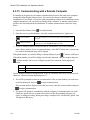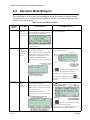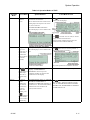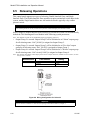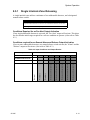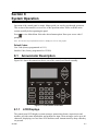
1
Section 8
System Operation
Operation of the control panel is simple. Menus guide you step-by-step through operations.
This section of the manual is an overview of the operation menus. Please read this entire
section carefully before operating the panel.
Press
to view Main Menu: Select the desired menu option. Enter your access code if
prompted.
Note: See Section 7.8 for information on how to modify user access code profiles.
Default Codes:
User Code (factory-programmed as 1111).
Installer Code (factory-programmed as 123456).
8.1
Annunciator Description
Figure 10-1 shows the annunciator that is part of the control panel board assembly.
Figure 8-1 Control Panel Annunciator
8.1.1
LCD Displays
The control panel LCD displays system messages, annunciates alarms, supervisories and
troubles; provides status information; and prompts for input. These messages can be up to 80
characters, displaying over four lines of 20 characters each. Annunciator keys beep when they
are pressed.
151295
8-1
Model 5700 Installation and Operation Manual
8.1.2
Banner
The banner is the message that displays on the control panel when the system is in normal
mode (no alarm or trouble condition exists and menus are not in use). You can create a
customized message that will display instead of the internal (default) message. See Section
7.5.9 for information on customizing the banner.
Figure 8-2 Banner Display Examples
8.2
Menu System
The control panel is easy to operate from Main Menu. To view the Main Menu press the
or
button on the control panel or remote annunciator, then turn the firefighter’s key
clockwise or enter your access code. The Main Menu will appear as shown in Section 8.2.1.
Select the desired option. If you have entered a code or firefighter’s key does not have access
to the menu item you have selected the following display message will appear:
-Access denied.Entered PIN does not
allow access to this
function.
You must enter an access code with the correct profile settings to gain access to that menu
item.
The control panel supports up to 20 access codes. The profile for each access code (or user)
can be modified through the programming menu option (see Section 7.8 for access code
programming).
8-2
151295
System Operation
8.2.1
Main Menu Overview
The chart below is a brief overview of the Main Menu. These options are described in greater
detail throughout this section of the manual.
Main Menu Options
8.2.2
Description
From here both menus can access Fire Drill and Indicator Test.
1
System Tests
2
Point Functions
3
Event History
4
Set Time and Date Set time and date for the system.
5
Printer Options
Options for controlling a printer if attached to the system. If a printer is used,
the Model 5824 Serial/Parallel Interface must be used.
6
Reset Dialer
Cancel any attempt to call the central station. Any calls awaiting additional
attempts will be aborted.
7
Program Menu
Brings up a set of menus for programming the panel, including changing
access codes. These options are described in detail in Section 7.
8
System Info
View system information, including model and serial numbers and revision
number and date.
9
Up/Download
Initiate communication from the panel site between the panel and a
computer running the Silent Knight Software Suite.
From here both menus can enable / disable points.
Display event history on the LCD. See Section 8.3.3 for more information.
Using the Menus
To move through the menus:
Use
and
previous menu.
To select an option:
Enter the number of the option.
–OR–
to move through the options in a menu. Use to move to a
Press
(Enter key) if the option appears at the top of the menu (= symbol
displays after the option number in this case).
8.3
8.3.1
Basic Operation
Setting Time and Date
1. From the Main Menu, select
4
for Set Date and Time.
2. Make changes in the fields on the screen. Use (right arrow) to move through the fields.
Use the
and
to select options in the fields.
3. When the date and time are correct, press
151295
.
8-3
Model 5700 Installation and Operation Manual
8.3.2
Disable / Enable a Point
1. From the Main Menu, select
2. Select
1
2
for Point Functions.
for Disable/Enable Point. A list of modules displays.
3. Use and to move through the list. Press
to select the module where the point you
want to disable/enable is located. A description of the point should display. The fourth line
of the screen should show "NORMAL" (meaning that the point is currently enabled) or
"DISABLED" (the point is currently disabled). Press to toggle between NORMAL and
DISABLE.
8.3.3
View Event History
Use the View Event History feature to display events on LCD. From the Main Menu, press
3 to select Event History. Events will begin displaying with most recent events first.
The panel can store up to 1000 events. When it reaches its 1000-event capacity, it begins
deleting, starting with the oldest events.
If a printer is attached to the system (via a Module 5824 Serial/Parallel Interface), you can
print event history (see Section 8.3.16).
The Silent Knight Software Suite (SKSS) can be used to retain more than 1000 events and to
create event history reports.
8.3.3.1 To clear the event history
From the Installer menu select
History Buffer.
8.3.4
6
Clear
Conduct a Fire Drill
1. From the Main Menu, press
2. Press
for System Tests. From the test menu select
1
1
1
for System Tests.
for Fire Drill. You will be prompted to press
3. The drill will begin immediately after you press
.
.
4. Press any key to end the drill. (If you do not press any key to end the fire drill manually, it
will time out automatically after one hour.)
If a fire drill switch has been installed, activating the switch will begin the drill; deactivating
the switch will end the drill.
8-4
151295
System Operation
8.3.5
Conduct an Indicator Test
The indicator test checks the annunciator LEDs, PZT, and LCD display.
1. From the Main Menu, press
1
for System Tests.
2. Press 2 for Indicator Test. The system turns on each LED several times, beeping the
PZT as it does so. At the same time it scrolls each available character across the LCD. A
problem is indicated if any of the following occurs:
•
An LED does not turn on;
•
You do not hear a beep;
•
All four lines of the LCD are not full.
This test takes approximately 15 seconds to complete. You can press any key to end manually
while the test is still in progress. When the test ends, you will be returned to the <Test Menu>.
8.3.6
Conduct a Walk Test
1. From the Main Menu, press
1
for System Tests.
IMPORTANT!
If any alarm verification zones are being used, the user will be asked if they wish to
disable alarm verification during walk test. This occurs for either walk test option.
2. Select 3 for Walk Test-No Rpt. The LCD will display "WALK TEST STOPPED" on
Line 1 and "ENTER = start test" on Line 2. If you select this option, central station reporting will be disabled while the test is in progress.
Select 4 for Walk Test-with Rpt. The LCD will display "WALK TEST STOPPED" on
Line 1 and "ENTER = start test" on Line 2. If you select this option, central station reporting will occur as normal during the walk test.
The panel generates a TEST report to the central station when the walk test begins. During
a walk test, the panel’s normal fire alarm function is completely disabled, placing the
panel in a local trouble condition. All zones respond as 1-Count zones (respond when a
single detector is in alarm) during a walk test. Each alarm initiated during the walk test
will be reported and stored in the event history buffer.
3. Enter the number of seconds you want the notification appliance circuits to sound. From 6
to 180 seconds.
4. Press
to end the walk test. The system will reset. The panel will send a "TEST
RESTORE" report to the central station.
If you do not end the walk test manually within 60 minutes, it will end automatically. If an
alarm or pre-alarm condition is occurring in the system, you will not be able to enter the walk
test.
Note: the panel does not do a full 30 second reset on resettable power outputs. As soon as the device is back to
normal, the panel is ready to go to the next device.
151295
8-5
Model 5700 Installation and Operation Manual
8.3.7
Conduct a Dialer Test
1. From the Main Menu, press
1
for System Tests.
2. Select 5 for Dialer Test. The screen will display “Manual dialer test started”. When the
test is completed, you will be returned to the <Test Menu>.
8.3.8
Silence alarms or troubles
Press
and enter your code or rotate the key at the prompt. If an external silence switch
has been installed, activating the switch will silence alarms or troubles. If you are already
using system menus when you press
key.
, you will not need to enter your code or rotate the
Note: Alarm and trouble signals that have been silenced but the detector remains un-restored will un-silence
every 24 hours until it is restored.
8.3.9
Reset alarms
Press
and enter your code or rotate the key at the prompt. If an external reset switch has
been installed, activating the switch will reset alarms. If you are already using system menus
when you press
, you will not need to enter your code or rotate the key.
8.3.10 Check Detector Through Point Status
The control panel constantly monitors smoke detectors to ensure that sensitivity levels are in
compliance with NFPA 72.
If sensitivity for a detector is not in compliance, the panel goes into trouble, generating a CAL
TRBLE condition. A detector enters a CAL MAINT state to indicate that it is approaching an
out of compliance condition (but is currently still in compliance).
When a CAL TRBLE condition occurs, the central station receives a detector trouble report
(“373” + Zone # for Contact ID format; “FT” + Zone # in SIA format).
To check sensitivity for an individual detector, follow the steps below. Section 8.3.16 provides
instructions for printing the status of all detectors in the system.
1. From the Main Menu, press
2. Press
2
2
for Point Functions.
for Point Status.
3. Select the module where the point you want to check is located.
4. Enter the number of the point you want to check and press
8-6
.
151295
System Operation
5. A screen similar to those shown in Figure 8-3 will display.
Figure 8-3 Checking Detector Sensitivity Compliance
If a printer is attached to the system (via a Module 5824 Serial/Parallel Interface), you can
print detector status (see Section 8.3.16).
8.3.11 View Status of a Point
1. From the Main Menu, select
2
for Point Status.
2. From the list that displays, press
to select the module where this point is located. The
screen that displays will show you if the point has a trouble and will provide sensitivity
compliance information. (See Section 8.3.10 for complete information about detector sensitivity compliance.)
8.3.12 View Alarms or Troubles
When the system is in alarm or trouble, you can press
trouble. See Section 8.3.12 for more information.
to view the location of an alarm or
8.3.13 View System Information
Press 8 from the Main Menu to view the panel model and serial number and system version
number and date. The information displays for several seconds then returns to the main menu.
8.3.14 Reset dialer
From the Main Menu, select 6 . The LCD will display “Dialer reset in progress...” You will
be returned to the Main Menu when the reset is completed.
151295
8-7
Model 5700 Installation and Operation Manual
8.3.15 Communicating with a Remote Computer
An installer at the panel site can initiate communications between the panel and a computer
running the Silent Knight Software Suite. You can use this feature to upload a panel
configuration. For example, if you have made programming changes to an installation on site
using an annunciator, you can send your changes to the computer, so that the central station
will have the latest data about the installation. To initiate communication, follow the steps
below.
1. From the Main Menu, select
9
for Up/Download.
2. From the next screen that displays, select the communication device. Options are:
1
= Internal Modem
If you select this option, you will use the panel’s built-in modem to call
the panel.
2
= RS232 connection
If you select this option, the panel and a computer are both on-site
connected via a 9-pin straight-through serial cable.
3. If you are using the panel’s internal modem to communicate, you will be prompted to
enter a phone number. If you are communicating via the RS232 connection, a phone number is not needed and this step will be skipped.
If the phone number you will be calling is already displayed, press
. Continue with Step 4.
If the phone number you will be calling is not already displayed, enter the number and press
. A phone number can be up to 24 digits long and can contain the following special
characters.
#
Pound (or number) key on the telephone
*
Star key on the telephone
,
Comma (character for 2-second pause)
Use the number buttons on the annunciator or the up- and down-arrow keys to select special
characters. Characters begin displaying after “9”.
4. You will be prompted to enter an account number. If the account number you want to use
is already displayed, just press
to begin communication.
If the account number displayed is not the correct one, enter the account number and press
to begin communication.
5. The panel will attempt to communicate with the computer. If communication was established, the upload task you created will be placed on the Downloading Software job
queue, awaiting processing. When processing is completed, an “Unsolicited Upload” task
will appear in the queue.
8-8
151295
System Operation
8.3.16 Working with a Printer
If you are using the Model 5824 Serial/Parallel Interface, several printing options are
available. See Section 4.6 for information about installing the 5824.
1. From the Main Menu, select
5
Printer Options.
2. From the next screen, select the 5824 module where the printer is connected.
3. If the printer is not currently busy printing another report, a screen with the following
options will be available. If the printer is busy, a message will display. You can press
to cancel the current print job. These options will then display.
1
Table 8-1: Printer Options
1 = Event Logging
Enables event logging, which causes the printer to continuously print events as they occur. The
date/time will print in 24-hour military format. Once event logging is enabled, it will remain
enabled until canceled by the installer. If you need to disable event logging, return to this
option and press
1
to disable.
EVENT LOG:
Sample Event Log
02/17/97
02/17/97
02/17/97
02/17/97
11:23
11:24
14:30
15:01
Event:
Event:
Event:
Event:
STARTED: 02/17/97 02:23
System Silenced
System Reset
Local Programming Begin
Local Programming Ended Successfully
EVENT LOG:
= Print Event
History
2
Sample Event
History Print-Out
Prints the up-to-1000 events currently stored in the panel’s event history buffer. Events print
starting with the newest. The date and time printed will be when the event actually occurred
and will print in 24-hour military format.
EVENT HISTORY:
02/20/97 09:02
02/20/97 09:05
02/22/97 08:47
02/22/97 08:52
02/25/97 15:54
02/25/97 16:10
02/28/97 12:50
02/28/97 13:31
.
.
.
= Print Detector
Status
3
STOPPED: 02/17/97 15:02
Event
Event
Event
Event
Event
Event
Event
Event
3
2
4
4
5
5
6
2
of
of
of
of
of
of
of
of
10:
10:
10:
10:
10:
10:
10:
10:
PRINTED: 02/28/97 13:35
System Silenced
System Reset
Printer Off Line 4
Printer On Line 4
Local Programming Begin
Local Programming Ended Successfully
Walk Test Begin
Walk Test End
Prints the current status of all detectors in the system. This is a method for finding out if any
detectors are out of NFPA compliance or any detectors need maintenance (are approaching an
out of compliance condition).
Sample Detector
Status Print-Out
Note: Detector status can also be viewed and printed using the SKSS or SKSS Facility Management Software.
151295
8-9
Model 5700 Installation and Operation Manual
8.4
Operation Mode Behavior
The control panel can be in one of seven conditions at any given moment: Normal, Alarm,
Prealarm, Supervisory, Trouble, Silenced, and Reset. Table 8-2 describes the behavior of the
panel in each of these modes.
Table 8-2: Operation Modes of FACP
Operation
Mode
Normal
Occurs When
System Behavior
In This Mode You Can
Enter the appropriate code, or rotate the key to
SYSTEM POWER LED is on.
No alarm or
trouble conThe All Systems Normal display indicates activate the Main Menu.
dition exists and that the system is in normal mode.
menus are not in
use.
The current date and time display on the
last line of the LCD.
Alarm
A smoke
detector goes
into alarm or a
pull station is
activated.
The dialer seizes control of the phone line
and calls the central station.
Press the down arrow to view the alarm. A screen
similar to this one displays.
The on-board annunciator sounds a loud,
steady beep (any notification devices
attached to the system will also sound).
GENERAL ALARM LED flashes.
The LCD displays a screen similar to this
one.
Press
and enter an access code (or activate
the key) to silence the annunciator (and any
notification devices attached to the system).
When the alarm condition clears, press
and
enter a code (or activate the key) to restore the panel
to normal.
Supervisory
The system
detects a
supervisory
condition.
The dialer seizes control of the phone line
and calls the central station.
Press
(down arrow) to view the supervisory
condition. A screen similar to this one displays.
The on-board annunciator sounds a loud,
pulsing beep in the sequence one second
on, one second off.
SUPERVISORY LED flashes.
The LCD displays a screen similar to this
one.
Press
and enter an access code (or activate
the key) to silence the annunciator.
Once the supervisory condition has been corrected,
the system will restore itself automatically.
8-10
151295
System Operation
Table 8-2: Operation Modes of FACP
Operation
Mode
Trouble
Occurs When
System Behavior
A system trouble The dialer seizes control of the phone line
and calls the central station.
condition
occurs.
The on-board annunciator sounds a loud,
pulsing beep in the sequence one second
on, nine seconds off.
In This Mode You Can
Press
(down arrow) to view the trouble. A screen
similar to this one displays.
SYSTEM TROUBLE LED flashes.
The LCD displays a screen similar to this
one.
Press
and enter an access code (or activate
the key) to silence the annunciator.
Once the trouble condition has been fixed, the
system will restore itself automatically.
Prealarm
A single detector Touchpad PZT beeps.
trips in a 2The LCD displays a screen similar to this
Count zone. (2- one.
Count means
two detectors
must trip before
an alarm is
reported.)
Press
(down arrow) to view the prealarm. A
screen similar to this one displays.
All system operations are available in this mode.
Reset
Silenced
The
button is pressed
followed by a
valid code or
rotation of the
key.
An alarm or
trouble
condition has
been silenced
but still exists.
To silence
alarms and
troubles, press
All LEDs are on briefly then the LCD
displays "ALARM RESET IN
PROGRESS". If the reset process
completes normally, the date and time
normal mode screen displays.
Menus are not available during the reset process.
SYSTEM SILENCE LED is on. SYSTEM
TROUBLE, SUPERVISORY or
GENERAL ALARM LED (depending on
condition) is on. The annunciator (and any
notification devices attached to the
system) will be silenced.
Press
(down arrow) to view the location of the
alarm or trouble. When the condition no longer
exists, the SYSTEM SILENCED and SYSTEM
TROUBLE LED, SUPERVISORY or GENERAL
ALARM LEDs turn off.
followed
by the Installer
or User Code or
rotate the key.
151295
8-11
Model 5700 Installation and Operation Manual
8.5
Releasing Operations
This control panel supports two types of releasing, Double Interlock Zone, and Single
Interlock Zone. The Double Interlock Zone operation requires an interlock switch input in the
system, and the Single Interlock does not. An interlock switch is typically a dry-contact
pressure switch.
Important!
These releasing functions can only be done if the system has a 5496 intelligent power module included.
When a Single or Double Interlock Zone releasing is selected the system is will automatically
default the 5496 Intellingent Power Module in the following system parameters:
Note: The defaults created can be modified through programming if desired.
•
Output Group 2 is created. Output Group 2 will be defaulted as an "Alarm" output group
for all releasing zones. NAC [01:001] is assigned to Output Group 2.
•
Output Group 3 is created. Output Group 3 will be defaulted as an "Pre-Alert" output
group for all releasing zones. NAC [01:002] is assigned to Output Group 3.
•
Output Group 4 is created. Output Group 4 will be defaulted as a "Release" output group
for all releasing zones. NAC circuit [01:003] is assigned to Output Group 4.
Note: The installer must define which input points will be used for detectors, manual release switches, or interlock/pressure switches.
Manufacturer
Asco
Part Number
Rating
T8210A107
24 VDC
8210G207
24 VDC
The Model 7641
Must be located
at the solenoid.
Figure 8-4 Wiring Configuration for Solenoid
Important!
Detectors must be installed at 0.7 times the linear spacing as described in NFPA 72, Chapter 2.
8-12
151295
System Operation
8.5.1
Single Interlock Zone Releasing
A single interlock zone utilizes a minimum of two addressable detectors, and a designated
manual release switch.
Important!
Only addressable detectors can be used. No conventional detectors can be used.
Each Single Interlock Zone input requires at least one manual release switch.
Conditions Required for an Pre-Alert Output Activation
If any single addressable detector is activated, the "Pre-Alert" output will activate. This alerts
the user that the initial stages required for a release condition are present. (Also refer to Table
8-3.)
Conditions required for an General Alarm and Release Output Activation
If two or more addressable detectors, or a manual release switch activate, the "Alarm" and the
"Release" outputs will activate. (Also refer to Table 8-3.)
Table 8-3: Input Conditions and Output Results
Inputs
Output Results
4
151295
4
4
4
4
4
Release and General Alarm
Release and General Alarm
Pre-Alert
Pre-Alert
Normal
Manual Release Station
4
Release and General Alarm
4
4
Release and General Alarm
4
2nd Addressable Detector
4
Release and General Alarm
4
1st Addressable Detector
8-13
Model 5700 Installation and Operation Manual
8.5.2
Double Interlock Zone Releasing
A Double Interlock Zone uses a minimum of two Addressable detectors, a designated manual
release switch, and an interlock switch input. An interlock switch is typically a dry-contact
pressure switch and will be referred to as an interlock/pressure switch in this document.
Important!
Only addressable detectors can be used. No conventional detectors can be used.
Each Single Interlock Zone input requires at least one manual release switch.
Each Double Interlock Zone input requires at least one Interlock/pressure switch
Conditions Required for a Pre-Alert Output Activation
If any single addressable detector is activated, the "Pre-Alert" output will activate. This alerts
the user that the initial stages required for a release condition are present. (Also refer to Table
8-3.)
Conditions Required for a General Alarm Output Activation
If two addressable detectors, a manual release switch is activated, or an interlock switch is
active, the "Pre-Alert", and "General Alarm" outputs will activate.
Conditions Required for a Release Output Activation
Any release requires the activation of an interlock switch, and either a manual release switch
or 2 activated addressable detectors. When these conditions are met, the "Release" and
"General Alarm" outputs will activate, and the "Alert" outputs will deactivate.
Inputs
Output Results
8-14
Pre-Alert and General Alarm
Pre-Alert and General Alarm
Pre-Alert and General Alarm
Pre-Alert and General Alarm
Pre-Alert and General Alarm
Pre-Alert
Pre-Alert
Normal
Interlock/Pressure Switch
4
4
4
4
4
4
4
4
4
4
4
4
4
4
Release and General Alarm
4
4
4
Release and General Alarm
4
4
4
Release and General Alarm
4
4
4
Release and General Alarm
4
Manual Release Station
4
4
Release and General Alarm
4
4
Pre-Alert and General Alarm
4
2nd Addressable Detector
4
Pre-Alert and General Alarm
4
Pre-Alert and General Alarm
4
1st Addressable Detector
151295