1
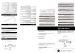
UNDERFLOOR HEATING SYSTEMS
DETAILS AND NOTES
CONTENTS
1
MANIFOLD DETAILS AND DIMENSIONS
2
TYPICAL CIRCUIT LAYOUT DETAILS
3
JOISTED SYSTEM DETAIL ( PLATES FROM ABOVE )
4
JOISTED SYSTEM DETAIL ( PLATES FROM BELOW )
5
SOLID FLOOR DETAIL ( COUNTERFLOW )
6
SOLID FLOOR DETAIL ( SERPENTINE )
7
TYPICAL 4 PORT MANIFOLD LAYOUT PLAN
8
FIXING DETAILS
9
EXAMPLE UFH SYSTEM
10
EXAMPLE UFH & RADIATOR SYSTEM
ANNEXE A
A
UFH START UP & PRE-COMMISIONING PROCEDURE
ANNEXE B
B
UFH FINAL COMMISSIONING PROCEDURE
DETAILS & NOTES
MANIFOLD SET-UP & DIMENSIONS
DATA SHEET 1
JUNE 2009
Horton Rd, West Drayton, Middlesex UBL 8JL
Tel. 01895 449233 Fax. 01895 422086
www.speedfit.co.uk
Technical Helpdesk 01895 425333
SHEET 2
Issue 2 – FEB 07
TYPICAL PIPE LAYOUT DETAIL 1 "COUNTERFLOW " PATTERN
Flow pipe laid next to
external wall first
Pipe Laid 100mm from
face of wall to avoid
fixings etc
Pipe Laid @ 200mm
centres
UFH Circuit Return
UFH Circuit Flow
Installation Notes
Pipe normally laid
in floor at 200mm
centres.
Uses only 90° bends
which reduces mechanical
stress on tube.
Suitable for any size &
shape area.
Not Suitable for battened
floors
Provides even temperature
distribution across flow as
flow & returns altenate.
TYPICAL PIPE LAYO UT DETAIL 2
"COUNTERFLOW " PATTERN W ITH PERIMETER ZONE.
Installation Notes
As detail 1 other than
pipe norm ally laid in floor
Perim eter Zone as part of
at 200mm centres with
m ain circuit. Closer pipe
closer pipe spacing of
spacing of 100mm centres
100m m at high heatloss
in strip m ax 1m wide
areas as determined
(BSEN1264).
by design criteria.
(refer to manifold installation
data sheets supplied with
UFH Circuit Return
final quote)
UFH Circuit Flow
TYPICAL PIPE LAYOUT DETAIL 3 "DOUBLE MEANDER"
UFH Circuit Return
UFH Circuit Flow
Installation Notes
Pipe normally laid in floor at
200m m centres.
Uses only 90° & 180° bends
which requires min 175mm
bending radius must be observed
to minimise m echanical stress on tube.
Suitable for large open areas.
Suitable for battened / screed floors
Provides relatively even temperature
distribution across flow as
flow & returns altenate.
Perimeter zones difficult to achieve
if specified.
TYPICAL PIPE LAYO UT DETAIL 4
"SINGLE SERPENTINE / SINGLE MEANDER" PATTERN
Installation Notes
Pipe norm ally laid in floor at 200mm
centres.
Uses only 180° bends
which requires m in 175mm
Higher output
bending radius m ust be observed
area
to minim ise mechanical stress on tube.
Suitable for any shape / area.
Suitable for battened / screed floors
Heat output is concentrated in part of area.
Perim eter zones difficult to achieve
UFH Circuit Return
if specified.
UFH Circuit Flow
Horton Rd, West Drayton, Middlesex UBL 8JL
Tel. 01895 449233 Fax. 01895 422086
www.speedfit.co.uk
Technical Helpdesk 01895 425333
SHEET 3
Issue 2 – FEB 07
Traditional Joists @ 400mm c/c
Pipe fixed to plates from above.
Floor Covering (Typically Carpet / Vinyl)
22mm Chipboard Floor Deck
(Screwed and Glued to Joist)
Thin polythene sheet to reduce noise due to expansion
Traditional Joists @ 400mm c/c (1 plate / joist spacing)
390mm x 1000mm Heat Spreader Plates
15mm Speedfit Tube
Mineral W ool or Rigid Foam Board Insulation
to building regs.
Plasterboard Ceiling
TYPICAL PIPE LAYOUT FOR TIMBER FLOOR "SINGLE
SERPENTINE / SINGLE MEANDER" PATTERN DETAIL 5
UFH Circuit Return
UFH Circuit Flow
Installation Notes
Pipe laid in floor at 200mm
centres.
Uses only 180° bends
which requires min 175mm
bending radius must be observed
to minimise mechanical stress on tube.
Suitable for joisted floors @ 400mm.
Heat output is concentrated in part of area.
Perimeter zones difficult to achieve
if specified.
TYPICAL PLATES FROM ABOVE INSTALLATION
Horton Rd, West Drayton, Middlesex UBL 8JL
Tel. 01895 449233 Fax. 01895 422086
www.speedfit.co.uk
Technical Helpdesk 01895 425333
SHEET 4
Issue 2 – FEB 07
I beam Joists @ 600mm c/c
Pipe fixed to plates from below.
Floor Covering (Typically Carpet / Vinyl)
22mm Chipboard Floor Deck
(Screwed and Glued to Joist)
TJI Joists at @ 600mm c/c (3 Plates / joist spacing)
Heat Spreader Plates
15mm Speedfit Tube
Mineral Wool or Rigid Foam Board Insulation
to building regs.
Plasterboard Ceiling
TYPICAL PIPE LAYOUT FOR TIMBER FLOOR "SINGLE
SERPENTINE / SINGLE MEANDER" PATTERN DETAIL 6
UFH Circuit Return
UFH Circuit Flow
Installation Notes
Pipe laid in floor at 200mm
centres.
Uses only 180° bends
which requires min 175mm
bending radius must be observed
to minimise mechanical stress on tube.
Suitable for joisted floors @ 400mm &
600mmc/c.
Heat output is concentrated in part of area.
Perimeter zones difficult to achieve
if specified.
TYPICAL PLATES FROM BELOW INSTALLATION
Horton Rd, West Drayton, Middlesex UBL 8JL
Tel. 01895 449233 Fax. 01895 422086
www.speedfit.co.uk
Technical Helpdesk 01895 425333
SHEET 5
Issue 2 – FEB 07
TYP IC AL PIPE LAYO U T D ETAIL 2
"C O U N TER FLO W " PATTER N W ITH PE R IM ETER ZO N E.
Perim eter Zone as part of
m ain circuit. C loser pipe
spacing of 100m m centres
in strip m ax 1m w ide
(BSEN 1264).
U FH C ircuit R eturn
U FH C ircuit Flow
Installation N otes
P ipe norm ally laid
in floor at 200m m
centres.
U ses only 90° bends
w hich reduces m echanical
stress on tube.
S uitable for any size &
shape area.
N ot S uitable for battened
floors
P rovides even tem perature
distribution across flow as
flow & returns altenate.
TYPICAL COUNTERFLOW INSTALLATION
Horton Rd, West Drayton, Middlesex UBL 8JL
Tel. 01895 449233 Fax. 01895 422086
www.speedfit.co.uk
Technical Helpdesk 01895 425333
SHEET 6
Issue 2 – FEB 07
TYPICAL PIPE LAYOUT DETAIL 4
"SINGLE SERPENTINE / SINGLE MEANDER" PATTERN
Installation Notes
Pipe normally laid in floor at 200mm
centres.
Uses only 180° bends
which requires min 175mm
Higher output
bending radius must be observed
area
to minimise mechanical stress on tube.
Suitable for any shape / area.
Suitable for battened / screed floors
Heat output is concentrated in part of area.
Perimeter zones difficult to achieve
if specified.
UFH Circuit Return
UFH Circuit Flow
TYPICAL SERPENTINE INSTALLATION
Horton Rd, West Drayton, Middlesex UBL 8JL
Tel. 01895 449233 Fax. 01895 422086
www.speedfit.co.uk
Technical Helpdesk 01895 425333
SHEET 7
Issue 2 – FEB 07
TYPICAL 4 PORT MANIFOLD INSTALLATION
Horton Rd, West Drayton, Middlesex UBL 8JL
Tel. 01895 449233 Fax. 01895 422086
www.speedfit.co.uk
Technical Helpdesk 01895 425333
SHEET 8
Issue 2 – FEB 07
PIPE FIXING APPLICATIONS
LONG PIPE STAPLE
Edge Insulation
Long Pipe Staples
Floor Covering
Screed
Polythene Layer
Insulation
Damp Proof Membrane
Sub Floor
Used for standard UFH screeded Floors, good for large areas and all types of pipe
pattern and irregular room shapes.
SHORT PIPE STAPLE
Edge Insulation
Short Pipe Staples
Floor Covering
Screed
Polythene Layer
Insulation
Damp Proof Membrane
Block & Beam Floor
Used for standard UFH screeded Floors, used where there is limited headroom and
intermediate floors where insulation can be reduced in depth.
FLOOR CLIP
Edge Insulation
Floor Clips
Floor Covering
Screed
Polythene Layer
Insulation
Damp Proof Membrane
Sub Floor
Used for standard UFH screeded Floors, supplied with the 1 Room Pack, good for
small areas with any pipe pattern and 1 person applications.
CLIP RAIL
Edge Insulation
Clip Rail
Floor Covering
Screed
Polythene Layer
Insulation
Damp Proof Membrane
Sub Floor
Used for standard UFH screeded Floors, good for large uniform areas with the
serpentine pipe pattern and 1 person applications.
Insulation depth 50mm min. for fixing application or conform to Part
L of the building regulations, whichever is greater.
Horton Rd, West Drayton, Middlesex UBL 8JL
Tel. 01895 449233 Fax. 01895 422086
www.speedfit.co.uk
Technical Helpdesk 01895 425333
SHEET 9
Issue 2 – FEB 07
WIRING CENTRE
BYPASS
VALVE
MCW
SUPPLY
HW SUPPLY
COMBINATION
BOILER
2 ZONE
VALVE
THERMOSTAT
WIRING CENTRE
MANIFOLD
&
PUMP PACK
THERMOSTAT
THERMOSTAT
EXAMPLE GROUND & FIRST FLOOR UFH
SYSTEM
Horton Rd, West Drayton, Middlesex UBL 8JL
Tel. 01895 449233 Fax. 01895 422086
www.speedfit.co.uk
Technical Helpdesk 01895 425333
SHEET 10
Issue 2 – FEB 07
BYPASS
VALVE
MCW
SUPPLY
HW SUPPLY
COMBINATION
BOILER
2 ZONE
VALVE
WIRING CENTRE
THERMOSTAT
EXAMPLE GROUND FLOOR UFH SYSTEM WITH
RADIATOR SYSTEM ON FIRST FLOOR
COMBINED HOTWATER
& PROGRAMMABLE ROOM
THERMOSTAT
PROGRAMMABLE ROOM
THERMOSTAT (UFH)
PROGRAMMABLE ROOM
THERMOSTAT
(RADIATOR /TOWELL RAD CIRCUIT)
JG TOUCHPAD
Notes
See Note 3
Note 1
When using Zones 7 or 8 for
controlling radiator circuits
instead of UFH, the switch on the zone
must be in the OFF position to prevent
the UFH pump from operating
This will result in fewer zones being
available for UFH.
The Zone Valve is activated by connecting
the demand wire (normally brown) to the
positive terminal of the appropriate actuator
connection as shown.
+ - A1 A2 B1 B2 Y B
+ - A1 A2 Y B
+ - A1 A2 Y B
Note 2
+ Y C
- B D
8 Core Beldon Cable
8 Core Beldon Cable
12v
12v
8 Core Beldon Cable
Up to 2 Actuators can be connected to the
same terminal. ie max 6 actuators per
zone block.
Note 3
12v
3 Amp Fused Spur
Network Connection to Other JGUH1
wiring centres. Boiler Enable to be
wired in parallel.
See Note 7
230v Mains AC Supply
(from common Boiler /
or System Spur)
MAINS IN
240v
BOILER ZONE1 / HW
ENABLE
+ A1 B1 Y
- A2 B2 B
IN OUT
L E N
ZONE 2
ZONE 3
ZONE 4
ZONE 5
ZONE 6
ZONE 7
ZONE 8
+ A1 Y
- A2 B
+ A1 Y
- A2 B
+ A1 Y
- A2 B
+ A1 Y
- A2 B
+ A1 Y
- A2 B
+ A1 Y
- A2 B
+ A1 Y
- A2 B
Note 4
Optional UFH Manifold Zone Valve
used only to prevent flow of water
to manifold when UFH is off and another
ciruit is in operation.
TOUCHPAD NETWORK
+ Y C
- B D
Y B
See Note 3
Heat Source
POWER
L SL
Boiler Enable
Volt free Switching
Can be used with
all boiler types
Max 5 amps
WATER
FUSE 1
VALVE
PUMP
FUSE 3
If Zone Valve is not used a link needs to
be placed between motorised valve
connections marked 1 & L to enable
boiler firing,
HEATING
ZONES
1
5
BOILER
2
6
3
7
4
8
Note 5 - Fuses
Fuse 1
Power Supply
LOW VOLTAGE
FUSE
(5 Amp)
Fuse 2
Power Supply to LV Transformer
(800ma Time Delay)
See Note 1
Optional Cylinder Stat
240v
+
-
Optional DHW Zone Valve
OUT IN
ZONE1
+
-
ZONE 2
+
-
ZONE 3
+
-
ZONE 4
+
-
ZONE 5
ZONE 6
OFF
+
-
OFF
Note 6 - Network Cable
-
ZONE 7
HOT WATER
CYLINDER
THERMOSTAT
HOT WATER
CYLINDER
VALVE
END SWITCH
L E N 1 2
+
-
ZONE 8
L E N
MANIFOLD
PUMP
1 2 L E N
END SWITCH
+
Fuse 3
Low Voltage
(800ma Time Delay)
ON
ZONE 8
ZONE 7
ON
Two Types are available
MANIFOLD
VALVE
240v
See Note 4
a) Cat 5e-ftp
8 Core Network Cable
(Max 30m Run)
b) Beldon 9538 Cable (Recommended)
8 Core Shielded Network Cable
(Max 100m Run)
240v
See Note 2
Note 7
When more than one JGUFH1 is used
in an installation the boiler enable terminal
must be connected to the boiler from each
individual wiring centre.
240v to UFH Pump
Optional UFH Zone Valve
240v
See Note 1
Optional Zone Valve for additonal heating
zone (Towell Rails / Radiators)
JG Speedfit Ltd., Horton Road West Drayton, Middlesex, UB7 8JL
Tel . 01895 449233
Fax . 01895 420321
www.speedfit.co.uk
[email protected]
UNDERFLOOR HEATING MANIFOLD
Technical Helpline 01895 425333
Electrical Installtion Helpline 01254 776343
JGUH1 Wiring Diagram 12v
Date : 17-09-08 Issue 3
Drawn By : MCC/NS
Notes
Fuses
Fuse 1 Power Supply
2.5A Slow Fuse
ROOM STAT
WITH SET BACK
(USING SET BACK
CHANNEL A)
Note 1
ROOM STAT
WITH SET BACK
(USING SET BACK
CHANNEL B)
PROGRAMMABLE
ROOM STAT
Up to 2 Actuators can be connected to the
same terminal. ie max 4 actuators per
zone block.
Note 2
Programmable Room Stats
See Note 4
Battery powered (3 x AA). Requires
only 2 wires to connect to wiring centre.
OPTIONAL 2 PORT
ZONE VALVE
Programmable Room Stats can be used
together with Set-Back Stats on the same
system.
Note 3
4
4
2
1
1/2
4
4
2
1
1/2
Set Back Control
PROBE
PROBE
Option 1
Plug-in Centralised System Timer
OPTIONAL 4 CHANNEL
REMOTE SYSTEM TIMER
Plugs directly into wiring centre &
offers 2 time set-back/low temperature
time channels (Channel A & B)
Option 2
Remote System Timer
ON
OFF
ON
RELAY 1
Hard wires into wiring centre time
channel A/B as per diagram.
RELAY 2
When a time channel is activated ,
this causes any Set-back thermostats
connected to that channel to operate
at 4°C lower than the temperature set
on the stat.
OFF
ON
RELAY 3
SL N PE
Factory fitted link
remove if using a
motorised valve
N
L
T1
T2
PE N SL
BOILER
NC COM NO
E
MAIN SUPPLY
UFH
FUSE 1
FUSE
BOILER RELAY
TWO PORT VALVE
PE N SL
230v Mains AC Supply
(from common Boiler /
or System Spur)
PUMP RELAY
OFF
UFH PUMP
1
1
1
1
ON
2
2
2
2
OFF
4
4
4
4
A
A
A
A
B
B
B
RELAY 4
See Note 5
See Note 3
B
1
1
1
1
2
2
2
2
The overall result is an automatic
reduction in room temperature during
the times programmed by
the user.
Note 4
3 Amp Fused Spur
Optional UFH Manifold Zone Valve
used only to prevent flow of water
to manifold when UFH is off and another
ciruit is in operation.
If Zone Valve is not used a link needs to
be placed between end switch connections
marked 1 & 2 to enable boiler firing,
See Note 2
Note 5
4 Channel Remote System Timer
Any free time channel not used as
per Note 3 can be used to provide
time control for DHW or radiator /
towel rail circuits.
L SL
Boiler Enable
OPTIONAL PLUG-IN SET BACK TIMER
Heat Source
UNDERFLOOR HEATING MANIFOLD
JG Speedfit Ltd., Horton Road West Drayton, Middlesex, UB7 8JL
Tel . 01895 449233
Fax . 01895 420321
www.speedfit.co.uk
[email protected]
See Note 3
Technical Helpline 01895 425333
Electrical Installtion Helpline 01254 776343
Wiring Diagram
230v 4 Zone Master
Wiring Centre
Date : 01-11-08 Issue 3
Drawn By : MCC/NS
Underfloor Heating System
Start-up & Pre-Commissioning
Procedure
Issue 2 - Jan 2005
With reference to British Standard EN 1264 and CIBSE Recommendations
BS EN 1264 requires the leak test and initial heat up to be recorded and documented. This form is
designed for this purpose and will also act as quality checking devise to assist in any future queries.
A. Project Details
Client
Project / Area / Room
B. Testing for leaks
All heating pipe circuits of the underfloor system are to be hydraulically wet tested for water leaks
before screeding is allowed to commence (BSEN 1264 :part 4 Para 4.3).
Testing should be completed in 2 stages. Firstly at 2 Bar for 10 minutes following by 10 Bar for a further
10 minutes. This testing, combined with visual and other relevant checks, should reveal installation
problems and is regarded as good plumbing practice.
It is important that all pipe circuits remain under pressure (normally 3-6 bar) during the screed laying
and curing process and every effort should be made to protect the pipework from damage
(BSEN1264 Part 4 Para 4.3).
Test pressure used
bar
Test Duration Used
Were any leaks present ? (if yes, please state action taken)
hrs/min
YES
NO
C. Heating-Up Conditions of the Floor Heating System (EN 1264 Part 4, Para 4.4)
This function has to be carried out on all heated floors. For Solid Floors with Cement screeds this must wait
until 21 days have elapsed after the screed has been laid. In the case of Anhydrite or Calcium Sulphate
screeds the elapsed time shall be only 7 days from the date of laying.
(Confirm this using the screed manufacturers’ information).
Confirm Screed type
Special Screed type
Cement screed
Polymer Modified
Anhydrite (calcium sulphate)
Asphalt (45oC max)
Date on which Screed Laying completed
Date of the Initial Heating-Up procedure
(Flow water temperature set at 25 ºC for 3 days)
Confirm Maximum Design Flow temperature (ºC)
Check manufacturers’ specifications for information,
which could affect the maximum temperature
(e.g. for floating floors etc).
Date when Maximum Flow temperature was set
(To be maintained for 4 days at this level)
External Temperature
The prevailing outside temperature during the warm-up was
JGS Underfloor Heating Warm Up Protocol Jan 2005
ºC
page 1 of 2
C. Initial Heating-Up Procedure of the Floor Heating System (EN 1264 Part 4, Para 4.4)
The warm up procedure should be carried out using natural infiltration and after switching-off all other
heating, all external doors and windows should be closed.
1. Ensure all heating circuits are filled with cold water and vent the system well using the standard
radiator style vents on the JG Manifold.
2. Fully close the JG Pump pack valve by turning the hand wheel clockwise.
3. Switch on the pump by turning all room thermostats to maximum.
4. Set the flow rate in the underfloor heating circuit to 4 l/min by adjusting the flow gauges on the
manifold.
5. Set the temperature limiter thermostat to 35°C (10°C above the initial target flow temperature
of 25 ºC)
6. Gradually open the Pump pack valve by turning the hand wheel anti-clockwise while monitoring the
flow temperature on the thermometer. This process may take approx. 10 minutes to commence in
order to take the inertia of the thermometer into account.
7. Gradually open the valve until the target flow temperature of 25 ºC is reached. It should be noted
that until the flow temperature reaches 47ºC, when the automatic injection valve takes over, the
controller only operates mechanically in the lower temperature range (25 ºC - 47ºC).
In other words, the flow temperature of the boiler must be constant (opening the valve limits the flow
rate in terms of volume and not temperature-dependent).
Use of the temperature limiter is essential (for safety reasons)
8. After the initial temperature is reached adjust the flow rate in the underfloor heating circuit to 2 l/min
9. The initial water flow temperature shall be maintained at 25ºC for 3 days.
10. On the 4th day the temperature can be increased gradually in increments of 5ºC/day until the
maximum design temperature is reached and must be maintained for a further 4 days at maximum
design flow temperature. Adjusting the hand wheel anti-clockwise does this. The overheat thermostat
should also be adjusted at this time to maintain a 10ºC difference. ie when the flow temperature is
40ºC the safety thermostat should be set at 50ºC.
11. When completed Speedfit recommend the room thermostats are adjusted to desired working levels
and the system operated normally for approx 2 weeks until final balancing, commissioning and
setting of circuit flow rates is carried out.
If Initial heating-up process was interrupted give details?
Please confirm the warm-up procedure was carried out in accordance with above by counter signing below.
Name (Print)
Name (Signature)
Date
Installer
Client / Clients
Representative
JG Speedfit
(if present)
John Guest Speedfit Limited
Horton Road, West Drayton, Middlesex UB7 8JL, England
Tel: 01895 449233 Fax: 01895-425319
JGS Underfloor Heating Warm Up Protocol Jan 2005
page 2 of 2
Issue 2 - Jan 2005
Underfloor Heating System
Final Commissioning
Procedure
With reference to British Standard EN 1264 and CIBSE
Recommendations
Customer
Project No.
Project
Address
Date
System Checks - ( To be completed for each manifold )
Final commissioning is required to ensure that the system will meet the design specification and meet the requirements of the
Building regulations. This procedure should only be carried out by a competent person and only after the system has been
running for a period in order to allow the floors to dry out and settle. The pre-commisoning and start-up procedure should
1 have been carried out before final commissioning . All building work should be complete and all window, doors etc should
be closed and all boiler, electrical and plumbing safety checks should have been completed by a competent person before
commencing commissioning. If floor coverings have been laid then these should be checked against the design specification
as there are occasions when coverings with high thermal resistance can result in design temperatures being unobtainable.
Visually inspect the installation including floor, components and manifold assembly and
check that the primary boiler flow and returns are correctly connected. Make a note on this
form of any items which need further investigation or remedial action. Check with the
responsible person that the Boiler is installed and working and that the system has been
2
made safe to inspect. If there is any doubt about the safety of the system, the wiring or any
other part of the installation do not proceed with commissioning and report your findings to
the appropriate person/authority. Remember all electrical work must be carried out in
accordance with the Building regulations and IEE regulations.
YES
NO
YES
NO
4 Check All rooms stats are initially set to 20°C
YES
NO
5 Check all floor thermostats, (if installed are set to 25°C to 30°C initially)
YES
NO
YES
YES
YES
YES
YES
NO
NO
NO
NO
NO
YES
NO
3
Start the system and Confirm Time Clock(s) / Programmer(s) are calling for
Heat.
Turn on each room stat to its maximum setting
and check that when any room stat calls actions
a) to d) occur:- If answer is no to any of these
6
questions, then the electrician should check for
electrical wiring for faults using the fault finding
guide supplied with the electrical info pack.
a) Is the boiler thermostat set correctly.
b) If fitted ,does the Zone Valve Operate
c) Does the boiler fire & system pump operate
d) Is supply hw available at the manifold
e) Does the UFH Pump begin to operate
Check that circuit actuators are opening. This can be done by visually
7 checking to see if a red marker is visible and if a flow can be seen on the
flow gauge.
Page 1 of 3
Confirm the flow temperature on the pump pack is reading the design
temperature. (The system should be given at least 2-hours to achieve if
starting from cold)
°C
8
This design temperature for each manifold can be found on the
Design & Installation Data Sheet supplied by the JG Speedfit
Design Office. Please call our technical helpline for copies of
these details prior to installation.
If the actual temperature is different to the design temperature, then record this
9 here before any further adjustment using the hand wheel. You should expect a time
lag for any changes to occur.
°C
With all zones calling for heat, record the actual flow rates in each circuit in the table below. This should be done
before any further adjustment is made, working from left to right on the manifold.
10
Circuit
(No)
Flow
(m/s)
Circuit
(No)
Flow
(m/s)
Circuit
(No)
Flow
(m/s)
Circuit
(No)
Flow
(m/s)
Circuit
(No)
Flow
(m/s)
Circuit
(No)
1
2
3
4
5
6
7
8
9
10
11
12
Flow
(m/s)
Record the flow rates specified on the design sheets in the table below.
This design temperature for each manifold can
be found on the Design & Installation Data
Sheet supplied by the JG Speedfit Design
Office. Please call our technical helpline for
copies of these details prior to installation.
11
Circuit
(No)
Flow
(m/s)
Circuit
(No)
Flow
(m/s)
Circuit
(No)
Flow
(m/s)
Circuit
(No)
Flow
(m/s)
Circuit
(No)
Flow
(m/s)
Circuit
(No)
1
2
3
4
5
6
7
8
9
10
11
12
Working from left to right on the manifold, adjust the flow rate of each circuit in turn until
the correct flow rate is met in table above. The method for this is shown on the leaflet
12 supplied with the manifold. When a full pass has been made along the manifold it may be
necessary to make further minor adjustments to individual circuits.
Flow
(m/s)
YES
NO
Recheck the manifold water flow temperature and adjust as necessary. Remember,
13 adjustments to the temperature may take a little time to be seen in the system.
YES
NO
Check all valves and flow meters are functioning and no leaks are present if any valves
14 have been adjusted.
YES
NO
Page 2 of 3
With the system running, check with the aid of an info red thermometer that the average
floor surface temperatures to not exceed 29°C, except in areas round the manifold or in
areas noted on the design drawings which show the use of perimeter zones where pipes
have smaller centres. These areas should not generally be greater that 35°C (BSEN1624).
The average floor surface design temperatures can also be checked. Remember, results
will depend on whether the specified floor covering is installed.
15
YES
NO
YES
NO
The design flow surface temperatures for each
zone are shown on the Manifold Installation
sheet supplied with the full design package.
(An indication of the presence on perimeter
zone spacing is also shown and denotes areas
of higher floor temperatures). Remember, the
floor finish will have an effect of floor
temperatures.
Once all checks have been completed and the system is working correctly, the
commissioning engineer should ensure that the user has been made aware of how the
system operates and how to, set the room thermostats and time controls. The user should
16
be left with a copy of the installation drawing, installation instructions together with the
commissioning and user documentation for their records.
Installer Details
Name
Address
17
Contact
Number
Signature
Date
Commissioning Engineer Details
Name
Address
18
Contact
Number
Signature
Date
JG Speedfit Representative (if Present)
Name
Address
19
Contact
Number
Signature
Date
Page 3 of 3