1
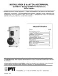
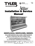
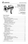
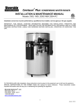
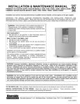
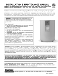
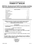
INSTALLATION & MAINTENANCE MANUAL EMX, EMXO and EMXGO SERIES WATER BOILERS Installation and service must be performed by a qualified service installer, service agency or the gas supplier. IMPORTANT: THIS MANUAL CONTAINS INFORMATION REQUIRED FOR INSTALLATION, OPERATION AND MAINTENANCE OF THIS EQUIPMENT. READ AND FOLLOW THE INFORMATION IN THIS MANUAL AND ALL OTHER PROVIDED INSTRUCTIONS, LABELS AND MARKINGS BEFORE INSTALLING, OPERATING OR SERVICING THIS UNIT. FOR YOUR SAFETY • Do not store or use gasoline or other flammable vapors or liquids in the vicinity of this or any other appliance. WHAT TO DO IF YOU SMELL GAS • Do not try to light any appliance. • Do not touch any electric switch; do not use any phone in your building. • Immediately call your gas supplier from a neighbor's phone. Follow the gas supplier's instructions. • If you cannot reach your gas supplier, call the fire department This product contains, or may come to contain materials identified as carcinogenic, or possibly carcinogenic to humans. Before installing, servicing or removing this product, read and follow the supplied instructions. WARNING: Improper installation, adjustment, alteration, service or maintenance can cause property damage, personal injury, exposure to hazardous materials or loss of life. Refer to the information contained in this manual. A qualified installer, service agency or the gas supplier, who must read and follow the supplied instructions before installing, servicing or removing this appliance, must perform installation and service. This appliance contains, or may come to contain materials that have been identified as carcinogenic, or possibly carcinogenic to humans. WARNING: Do not use this appliance if any part has been under water. Immediately call a qualified service technician to inspect the unit and to replace any part of the control system, any gas controls and any other items affecting safe appliance operation and which has been under water. Failure to follow these instructions can cause property damage, personal injury, exposure to hazardous materials or loss of life. TO THE INSTALLER: After installation, these instructions must be given to the equipment user or left near the appliance. SPECIAL INSTRUCTIONS TO THE OWNER: Retain this manual for future reference. These instructions contain important information that will help you in maintaining and operating this appliance. Riverside Hydronics®, LLC - 990 Haltom Road - Fort Worth, Texas 76117 - Tel 1-800-990-5918 34-503 07/13 EMX, EMXO and EMXGO SERIES WATER BOILERS TABLE OF CONTENTS 1. Safety Considerations 2. Typical Construction 3. Checking Equipment Before You Install 4. Warranty 5. Codes 6. Location 7. Installation 8. Service Clearances 9. Clearances to Combustible Surfaces 10. Electrical 11. Venting 12. Combustion & Ventilation Air Opening 13. Vent Termination 14. Start-up Procedures 15. Gas Piping 16. Oil & Gas/Oil Instructions 17. Maintenance 17.1 Maintenance & Safety Inspection Report 2 34-503 07/13 EMX, EMXO and EMXGO SERIES WATER BOILERS 1 SAFETY CONSIDERATIONS PRODUCT SAFETY INFORMATION REFRACTORY CERAMIC FIBER PRODUCT WITH CRYSTALLINE SILICA WARNING: This product contains crystalline silica, which has been identified by the International Agency for Research on Cancer (IARC) as carcinogenic to humans. This product also contains refractory ceramic fibers, which have been identified by the IARC as possibly carcinogenic to humans. Avoid breathing fiber particulates and dust. RISKS: • Airborne fibrous insulation is a possible cancer hazard by inhalation. • Airborne crystalline silica may cause silicosis (lung disease) by inhalation. • May cause temporary irritation to eyes, skin, and respiratory tract. PRECAUTIONARY MEASURES: • Minimize airborne fibers with engineering controls. • Use NIOSH/MSHA approved respirators as required (see MSDS). • Wear long sleeved, loose-fitting clothing, eye protection and gloves. FIRST AID MEASURES: (If any of the irritations listed persists, seek medical attention) Eyes: Flush with water. Skin: Wash with soap and warm water. Ingestion: Do not induce vomiting. Get medical attention if gastrointestinal symptoms develop. Inhalation: Remove to fresh clean air. WARNING: If you are unfamiliar with the safe handling of refractory ceramic fiber products, or if you wish additional information prior to beginning any disassembly of the water heater or boiler that might expose refractory ceramic fiber materials, contact: Unifrax Corporation, 2351 Whirlpool Street, Niagara Falls, NY 14305-2413, 1-800322-2293. IDENTIFICATION OF REFRACTORY CERAMIC FIBER MATERIALS (RCF): The Combustion Chamber contains RCF materials which are located within the product and are not generally exposed except during service, disassembly or assembly. 3 34-503 07/13 EMX, EMXO and EMXGO SERIES WATER BOILERS IMPORTANT SAFETY NOTE It takes only 5 seconds of skin contact with 140°F water to cause a second degree burn! You must protect against high water temperatures at all lavatories, tubs, showers and other points of hot water contact. Accidental scalding from high water temperatures is a greater risk in some types of installations. Some examples are: HOMES FOR THE MENTALLY HANDICAPPED HOMES FOR THE PHYSICALLY HANDICAPPED HOSPITALS AND NURSING HOMES ELDER CARE FACILITIES AND REST HOMES ORPHANAGES AND CHILD CARE FACILITIES OTHER INSTALLATIONS - WHERE RESPONSE TO CONTACT WITH HOT WATER MAY BE SLOWER OR WHERE THE DANGER OF HOT WATER CONTACT IS GREATER Thermostatically controlled mixing valves must be used in the design of the potable hot water system. Potable hot water should be tempered to no more than 110°F when used for bathing or other personal uses. Good engineering practice mandates the use of thermostatically controlled mixing valves set at 120°F or less to keep the delivered water temperature below scalding temperatures. 4 34-503 07/13 EMX, EMXO and EMXGO SERIES WATER BOILERS 2 TYPICAL CONSTRUCTION 1. FLUE OUTLET 7. BURNER 2. TEMPERATURE AND PRESSURE GAUGES 8. 3” HANDHOLE CLEANOUT 3. CONTROL ENCLOSURE 9. FLOAT LWCO (Optional) 4. GAS INLET 10. BOILER WATER RETURN 5. ASME PRESSURE RELIEF VALVE 11. BOILER WATER OUTLET 6. COMBINATION BOTTOM BLOWDOWN & DRAIN For connection points on oil pumps, see specific burner installation and maintenance instruction. 5 34-503 07/13 EMX, EMXO and EMXGO SERIES WATER BOILERS 3 CHECKING EQUIPMENT BEFORE YOU INSTALL Inspect the unit completely upon receipt from the freight carrier before signing the bill of lading. Inspect the appliance and all accompanying parts for signs of impact or mishandling. Verify the total number of pieces shown on packing slips with those actually received. Contact the freight carrier immediately if any damage or shortage is detected. 4 WARRANTY Factory warranty does not cover improper installation or operation. (See warranty for complete details). Warranty exclusions include but are not limited to failure or malfunctions resulting from: 1. 2. 3. 4. 5 Failures to properly apply, install, operate, or maintain the appliance in accordance to printed instructions. Abuse, alteration, accident, fire, flood and the like. Sediment or lime buildup, freezing or any other conditions causing inadequate circulation. Corrosive or contaminated atmosphere. CODES The equipment shall be installed in accordance with those installation regulations in force in the local area where the installation is to be made. These shall be carefully followed in all cases. Authorities having jurisdiction shall be consulted before installation is made. In the absence of such requirements, the installation shall conform to the latest edition of the National Fuel Gas Code, ANSI Z223.1 and with the National Electrical Code, NFPA 70. Where required by the authority having jurisdiction, the installation must conform to American Society of Mechanical Engineers Safety Code for Controls and Safety Devices for Automatically Fired Boilers, No. (CSD-1). All appliances conform to the latest edition of the ASME Boiler and Pressure Vessel Code, Section IV. Where required by the authority having jurisdiction, the installation must comply with the Canadian Association Code, CAN/CSA-B149.1 and/or B149.2 and/or local codes. 6 LOCATION 1. Locate the unit in a clean and dry area as close as possible to the greatest hot water usage and as near to gas, oil, steam, boiler water and/or electrical power as practical. 2. Install the unit on a firm and level foundation. 3. Locate the foundation on a pitched floor near a suitable drain, or make other provisions to prevent contact to areas of the building subject to water damage should the boiler or a water connection leak. The drain must be sufficient to contain water in excess of 210°F. 7 INSTALLATION WARNING: Use industry standard safe rigging methods when attempting to lift or move this product. Failure to follow these instructions could result in property damage, serious injury or death. One common method includes the use of straps and spreader bars, lifting from the water heater base skid assembly. 1. Check the data decal on the boiler. Be sure the electrical, water, oil, or gas supply is adequate for the installation. 2. Carefully remove all shipping supports and bracing. (Float type devices have shipping plugs blocking the float). 3. Install shut-off valves and unions on the inlet and outlet water piping for servicing. Use caution when threading pipe nipples into tank connections to prevent cross threading, or over-tightening. Always use a back-up wrench on tank nipples when tightening unions, valves, etc. 4. Insulate hot water and return circulation lines. Insulate cold water supply lines if subject to freezing during shutdown periods. IMPORTANT: Do not use the plumbing connected to the appliance as a ground for welding or any other purpose. 6 34-503 07/13 EMX, EMXO and EMXGO SERIES WATER BOILERS 5. The boiler is equipped with a temperature and pressure relief valve(s) rated for the input. Pipe the relief valve discharge to a suitable open drain. The drain pipe may not be smaller than the relief valve opening and must be secured to prevent it from lifting out of the drain under discharge pressure. Do not install valves or restrictions in the discharge line. 6. Pipe the drain valve to a suitable open drain. 8 SERVICE CLEARANCES Allow sufficient space to provide adequate clearances on all sides for service and inspection. Recommended clearance is 24” at the top and front, 18” at left and right sides of the appliance. Optional equipment may increase the clearance requirements. Allow sufficient space for installing and servicing connections such as water, gas, vent, combustion air, electrical, pump and other auxiliary equipment. 9 CLEARANCES TO COMBUSTIBLE SURFACES The appliance must not be installed on a combustible floor, or on a non-combustible floor covering combustible material. Clearance to unprotected combustible material must be 8” minimum at top, sides and rear, and 24” minimum in front. Recommended access for service is 18” at sides and rear and 24” in front. 10 ELECTRICAL WARNING: Turn off all electrical service to the appliance when accessing the controls located inside the control cabinet. The cabinet contains high voltage wiring and terminals. If the electrical service is not turned off and these wires or terminals are touched, a dangerous shock causing personal injury or loss of life could occur. Close the control cabinet before restoring electrical service to the appliance. 1. Wiring to the unit should conform to the National Electrical Code or the code legally authorized in your locality. A fused disconnect switch should be used for the boiler. When required, EPV boilers are equipped with step-down transformers located within the NEMA enclosure. This allows for an effective single point electrical connection to the boiler. 2. Be certain that high and low voltages are connected to the correct points. 3. When remote on/off or lead-lag enable operation is used, remove jumper from R1 and R2 and wire in series. 4. A proper earth ground for this unit must be provided. A single conductor ground wire pulled from the distribution panel to the sub panel (or some similar type) is recommended. CAUTION: Use only copper wiring of proper sizing for incoming service. Damage resulting from use of aluminum wiring will be excluded from coverage under the warranty of this unit. 7 34-503 07/13 EMX, EMXO and EMXGO SERIES WATER BOILERS 11 VENTING Vent this appliance in accordance with the latest edition of the National Fuel Gas Code and in accordance with the authority having jurisdiction. DRAFT REGULATORS POWER GAS or OIL TYPICAL THRU-WALL VENTING (See National Fuel Gas Code for complete requirements.) 8 34-503 07/13 EMX, EMXO and EMXGO SERIES WATER BOILERS 12 COMBUSTION & VENTILATION AIR OPENING Provisions for combustion and ventilation air must be in accordance with Section 5.3, Air for Combustion and Ventilation, of the latest edition of the National Fuel Gas Code ANSI Z223.1, or applicable provisions of the local building codes. The equipment room must be provided with two openings to assure adequate combustion air and proper ventilation. 1. If air is taken directly from outside the building (see Figure 1): a. Inlet air opening, 1 square inch per 2,000 Btu/h input. This opening must be located near the floor. b. Outlet air opening, 1 square inch per 2,000 Btu/h input. This opening must be located near the ceiling. 2. If air is taken from another interior space (see Figure 2), each opening specified above should have a minimum free area of 1 square inch per 1,000 Btu/h input. CONFINED AREA FIGURE 1 Equipment located in confined spaces; all air from outdoors CONFINED AREA FIGURE 2 Equipment located in confined spaces; all air from inside the building CAUTION: Under no circumstances should the equipment room ever be under negative pressure. Particular care should be taken when exhaust fans, compressors, air handling units, etc. may rob air from combustion equipment. The combustion air supply must be completely free of any chemical fumes. Common chemicals that must be avoided are fluorocarbons and other halogenated compounds most commonly present as refrigerants or solvents such as freons, tri-chlorethylene, perchlorethylene, chlorine, or salts for use in water softeners or any other heavy gas are particularly injurious and corrosive after contact with flames or hot surfaces. The result is improper combustion and premature equipment failure. 9 34-503 07/13 EMX, EMXO and EMXGO SERIES WATER BOILERS 13 VENT TERMINATION CAUTION: Never size a flue vent based only on the flue outlet size of the product. Vent installations for connection to gas vents or chimneys must be in accordance with Part 7, Venting of Equipment, of the latest edition of the National Fuel Gas Code, ANSI Z223.1, or applicable provisions of the building codes. 1. A flue vent passing through the roof must be terminated in accordance with Section 7.6.2, Gas Vent Termination, of the latest edition of the National Fuel Gas Code, ANSI Z223.1, or applicable provisions of the local building codes. 2. A gas vent passing through a wall must be terminated in accordance with Section 7.8, Through the Wall Vent Termination, of the latest edition of the National Fuel Gas Code, ANSI Z223.1, or applicable provisions of the local building codes. WARNING: Vent connectors serving appliances vented by natural draft shall not be connected into any portion of mechanical draft systems operating under positive pressure. Failure to observe this warning could result in property damage, serious injury or death. 3. The vent connector must be the same size as the product flue outlet. The vent size must be determined by the BTU input of the product(s) and the vent design. The horizontal breeching of a vent must have at least 1/4" rise per linear foot not to exceed the length of horizontal vent. CAUTION: Do not weld or support breaching to product flue outlet. Adequate support of the venting system must be provided in compliance with local or other applicable codes. WARNING: The appliance must use only draft regulators as supplied by the appliance manufacturer for these purposes. Failure to use the correct draft regulators could result in carbon monoxide poisoning causing personal injury or loss of life. 4. Draft regulators (barometric dampers) may be incorporated in the vent for gas, oil, and gas/oil fan assisted products and are recommended. A single swing barometric damper should be used for oil-fired products. The double swing type should be used on gas or gas/oil fired products. Under normal venting conditions, the draft regulator should be the same size as the flue outlet of the product, never smaller. Draft regulators must be installed and adjusted in accordance with the manufacturer's instructions. IMPORTANT: A minimum of -.02" to -.06" W.C. draft is required for appliances vented by natural draft. 10 34-503 07/13 EMX, EMXO and EMXGO SERIES WATER BOILERS 14 START-UP PROCEDURES WARNING: Start-up should only be performed by a qualified technician. CAUTION: Do not relight pilot or start burner with combustion chamber full of gas vapor, or with very hot combustion chamber. 1. Study the Installation & Maintenance manual for the burner carefully. 2. Fill the boiler tank with water. Open the relief valve to allow air in the tank to escape. Be sure all connections into the tank are tight, as leaks at tank fittings will damage the insulation. 3. Follow the enclosed warnings on the water temperature control when setting the operating thermostats. The boiler has two temperature controls. The top control is the temperature limiting device and should be set at 250°F. The lowest control is the operating thermostat and must be adjusted 10 degrees below the temperature limit. A common setting is 160°F for the operating thermostat. CAUTION: On models with flue gas recirculation (FGR), the FGR duct and plumbing will be hot during and after operation. Use care to avoid contact with skin while making adjustments. 4. Conduct the following gas train leakage test before start-up, annual intervals and prior to investigating the cause of any reported occurrences of delayed ignition. a. Using an appropriate bubble detection solution, thoroughly coat all gas train pipe connections. If any bubbles are detected, the leaking connection must be tightened, recoated and rechecked to assure stoppage of the leak. b. Attach a manometer, to measure gas pressure, at the manual gas shutoff valve located just upstream of the gas train. Adjust gas train inlet pressure to the specified value (e.g. 14 in. W.C.), and tightly close the gas train manual shutoff valve closest to burner. c. Reattach the manometer to the gas train manual shutoff valve at the burner and record the measured gas pressure in inches of water column (in W.C.). Measure gas pressure again after 15 minutes. If gas pressure has increased 0.5" W.C. or more, the gas leak must be isolated to one or more of the operating gas valves; for example, a solenoid actuated gas shutoff valve. After any leaking valve is replaced, the reassembled gas train must be leak tested again before start-up is attempted. 11 34-503 07/13 EMX, EMXO and EMXGO SERIES WATER BOILERS Record the following information for future use: 1. Manifold gas pressure: " W.C. 2. Vent pressure: " W.C. 3. O2 reading: % (5-7%) 4. CO2 reading: % (8-9%) 5. CO reading: ppm (less than 300 ppm) 6. NOx reading: ppm 7. Vent temperature: Gross °F. Less ambient °F. Net °F. 12 34-503 07/13 EMX, EMXO and EMXGO SERIES WATER BOILERS 15 GAS PIPING 1. Before making gas hook-up, verify that the unit is being supplied with same gas type as indicated on the data decal. 2. The maximum inlet gas pressure must not exceed the value specified. If delivery pressure is higher, a single suitable intermediate, lock-up type regulator must be installed ahead of the low-pressure regulator on the burner to reduce inlet pressure to acceptable limits. The regulator must have a flow regulating capacity suitable for the firing rate. 3. The gas supply line must be of sufficient size for length of run and pressure drop to furnish adequate gas pressure to allow the burner to develop its rated capacity. A drip leg should be installed ahead of burner piping connection, if not supplied (See Table 1). 4. Gas valves and gas regulators may contain bleed or vent ports. Local codes may require bleeds and vents to be vented to atmosphere outside the building. Consult local building codes for size and installation. PIPE SIZE Equivalent feet from meter Maximum Capacity for Natural Gas* MBTU/HR Based on 0.5" W.C. Pressure Drop* 1-1/4" 1-1/2" 2" 2½" 3" 4" 25 860 1320 2475 3900 7000 - 40 660 990 1900 3000 5300 - 60 - 810 1520 2400 4300 - 80 - 690 1300 2050 3700 - 100 - 620 1150 1850 3250 6700 125 - - 1020 1650 2950 6000 150 - - 950 1500 2650 5500 175 - - 850 1370 2450 5000 200 - - 800 1280 TABLE 1 2280 4600 *Multiplier for Propane: 1.57 **Multiplier for alternate pressure drops: 0.3" W.C. 0.77; 1.0" W.C. 1.41; 2.0" W.C. 2.00; and 4.0" W.C. 2.82. CAUTION: Be sure gas supply and vent lines have been cleaned of all debris, which could enter the regulators or burner system and cause malfunction or unsafe conditions. Pipe joint sealant should be used instead of tape and should be resistant to liquefied petroleum when LP gas is used. 16 OIL TANK AND SUPPLY LINES FOR OIL AND COMBINATION GAS/OIL WATER HEATERS 1. The oil tank construction and installation must meet local codes and should meet the specifications recommended by Underwriter's Laboratories (see Figure 3). IMPORTANT: The combination gas/oil burner requires a constant supply of fuel oil for pump lubrication, even when running on gas. Make sure the oil shutoff valve is open and oil is available at the pump when the burner is in service. If no oil supply is available and burner must be run on gas, remove the oil pump coupling on burner. A two-pipe system must be used at the burner inlet. A single pipe system may be used to supply local holding tanks at Individual burners (up to 50 gallons, or check your local codes), but provisions must be made for a return line from the burner oil pump to the holding tank. When a gravity feed system is used install anti-siphon valve close to tank in supply line. 13 34-503 07/13 EMX, EMXO and EMXGO SERIES WATER BOILERS 2. Oil supply and return lines must be installed below frost level. Below-floor-level runs are preferred inside the building. Avoid overhead runs, which can cause excess lift for the oil pump. Return lines must be as large as the supply lines with no shutoff valves in the line. If a shutoff valve is installed in existing return line piping, remove or open and disable it to prevent accidental closure. IMPORTANT: A supply line filter must be installed and cleaned or replaced regularly. 3. 90% of all oil pump problems resulting in poor cutoff, noisy operation and erratic firing are caused by air vacuum leaks in the supply (suction) line. To avoid air leaks, both return and supply lines should extend to near bottom of the oil tank. Only flare type fittings should be used, and all fittings and joints must be tight. Check and recheck all fittings and joints for air vacuum leaks. 4. Supply line size is based on the suction developed from the total "gear capacity" of the pump. The pump is a positive displacement type and pumps a constant volume of oil, only a portion of which is used by the nozzle(s), the remainder being bypassed to the return line. During gas operation on the combination gas/oil burner, the pump is operational, but all oil is bypassed to the return line. 5. No allowance has been made in the recommended supply lines sizes (see Table 2) for additional severe restrictions such as multiple elbows, etc. If in doubt of the size required, use the next size larger than recommended. The oil lines (especially the supply line) must be absolutely leak tight to prevent loss of prime. Do not use Teflon tape or oil soluble pipe dope. CAUTION: If the "lift" from the oil tank to the pump inlet is over 12 feet or if the "lift" plus the supply line pressure drop is such that the total suction at the pump exceeds 15" mercury, install a booster pump. Pressure at the burner inlet must not exceed 3 psi. RECOMMENDED OIL SUPPLY & RETURN LINES LIFT ABOVE TANK COPPER TUBING SIZE (OD) LENGTH OF RUN IRON PIPE SIZE LENGTH OF RUN 50' 100' 200' 50' 100' 200' 0 feet 1/2" 1/2" 5/8" 3/8" 3/8" 1/2" 5 feet 1/2" 1/2" 5/8" 3/8" 3/8" 1/2" 8 feet 1/2" 1/2" 5/8" 3/8" 3/8" 1/2" 12 feet 1/2" 5/8" 5/8" 3/8" 1/2" 1/2" TABLE 2 FIGURE 3 14 34-503 07/13 EMX, EMXO and EMXGO SERIES WATER BOILERS 17 MAINTENANCE CARBON MONOXIDE WARNING: An annual or seasonal combustion checkout must be performed by a qualified service agency to ensure safe operation. Failure to maintain proper combustion can result in injury or death. Periodic inspection and checkout of the burner ignition, control system, and fuel valve operation (for tight close-off) to ensure safe and reliable operation of this equipment. Refer to the burner installation instruction for recommendations. A preventive maintenance is recommended to assure a long, trouble-free life of the boiler. Refer to ASME Section VII for a comprehensive plan for boiler operation, maintenance and lay-up. Examine the venting system at least once each year for proper connections, alignment and corrosion. The blower inlet will collect dust from the air during operation. Disconnect the power to the heater and clean the blower wheel when necessary. Inspect all parts and make replacements when necessary. Check wiring for loose connections and burned wires. WARNING: Turn off all electrical service to the appliance when accessing the controls located inside the control cabinet. The cabinet contains high voltage wiring and terminals. If the electrical service is not turned off and these wires or terminals are touched, a dangerous shock causing personal injury or loss of life could occur. Close the control cabinet before restoring electrical service to the appliance. A table of periodic safety inspections is attached to this manual for ease of reference by the building service technician or licensed equipment operator (Table 3, page 17). Since boiler designs vary, only some of these listed inspections may be appropriate for your particular model. Proper water treatment is critical to prevent corrosion as well as to reduce scale, both of which will reduce the life of the boiler. Hydronic heating systems, steam heating systems and process steam systems all have different treatment requirements. The makeup of the water, just as the blowdown, will vary with each application. Rely on the recommendation of the water consultant. CAUTION: Turn off all manual valves and burner electrical switches before removing any part for service or cleaning. Do not push relay contacts in manually; accidental opening of main automatic valve can result. Ensure there is no pressure on the vessel prior to disassembly of any water carrying component to prevent serious injury. 1. Examine the venting system at least monthly for proper connections, alignment, or the presence of corrosion. If corrosion appears, the boiler must not be operated until the corroded vent section(s) is replaced. 2. Oil the blower motor and wipe oil and dust from the burner at regular intervals. The static fan will collect dust from the air during operation. Clean the screen and fan blades if necessary. The burner should be cleaned each year. Inspect all parts and make replacements when necessary. Check wiring for loose connections and burned wires. 3. Periodic inspections and check-out of the burner ignition system, control system and fuel valve operation (for tight close-off) should be made. Refer to the burner installation instructions for inspection recommendations. 4. Inspect operating controls to ensure they are level, especially those containing mercury switches. Make sure connecting tubing is not kinked or damaged on remote bulb thermostats. 15 34-503 07/13 EMX, EMXO and EMXGO SERIES WATER BOILERS 17 MAINTENANCE (con't) 5. The pressure safety valve should be checked at regular intervals by manually opening the valve. The openings inside the valve may become restricted by a buildup of scale and become inoperative. If the valve does not open and close properly, it must be replaced. Shut down boiler, relieve internal pressure, and replace safety valve with a like kind or one meeting the requirements stated on the rating decal located adjacent to the safety valve mounting location. CAUTION: The safety valve is a primary safety device. 6. The need to periodically check water level controls and waterside of the pressure vessel cannot be over emphasized. Most instances of major boiler damage are the result of operating with low water or the use of untreated (or incorrectly treated) water. 7. Every boiler is equipped with an electronic low water cutoff. This device senses continuity between a probe located in the top of the tank and the water to verify the presence of water. It is important to check the operation of this device periodically. 8. This boiler may be equipped with a float-type low water cutoff. Since low water cutoff devices are generally set by the original manufacturer, no attempt should be made to adjust these controls to alter the point of low water cutoff. If a low water device should become erratic in operation or if its setting changes from previous established levels, check for reasons and correct; repair or replace as required. The controls' operation may be checked by stopping the water supply to the boiler while the burner is operating at low fire. While under constant attendance allow the water to lower at a normal rate. If a control does not break the circuit to stop the burner at the proper point, then SHUT DOWN THE BURNER IMMEDIATELY. Do not restart until all cross connecting piping is checked for obstructions. Also check the float bowl. If these are clean, repair or replace the control. Repeat the above test to insure proper operation prior to returning the boiler to service. Remove the pipe plugs from the tees and crosses and make certain the cross connecting piping is clean and free of obstructions. Controls must be mounted in a plumb position for proper performance. Determine piping is vertically aligned after shipment and installation and throughout the life of the equipment. The operation of the electronic low water cutoff may be checked in the same manner, by bypassing the function of the float low water cutoff. 9. It is important to blowdown the float low water cutoff devices when supplied. It is recommended that a short blowdown be conducted daily. Float low water cutoffs should be equipped with test-n-check valves to allow blowdown of low water cutoff without requiring complete drainage of the boiler. 10. A boiler used for heating or seasonal loads or for standby service may have an extended period of nonuse. Special attention must be given so that neither waterside nor fireside surfaces are allowed to deteriorate from corrosion. 11. There are two methods of storage – wet or dry. Your water consultant or feedwater treating company can recommend the better method, depending upon circumstances in a particular installation. Section VII of the ASME Code also contains information relating to laying up a boiler. 12. Extended shutdown of the boiler and restarting are as follows: a. Turn off all power and fuel supplies. b. Enter boiler into dry storage. c. Tag power switch(s) that fuel is off and tank is in storage condition. d. Remove tank from storage and turn fuel and power switch(s) on to start. Reset all controls and conduct startup of the boiler as discusses previously. 16 34-503 07/13 EMX, EMXO and EMXGO SERIES WATER BOILERS 17.1 MAINTENANCE & SAFETY INSPECTION REPORT DATE Recommended Inspection Intervals BURNER COMBUSTION TANK TANK FLUSH PRV TEST & VENT THERMOSTAT GAS TRAIN INSPECTION ANALYSIS INSPECTION & CLEANOUT INSPECTION INSPECTION INSPECTION LEAK TEST YEARLY 6 MONTHS 6 MONTHS 3 MONTHS 6 MONTHS YEARLY YEARLY YEARLY TABLE 3 17 34-503 07/13 EMX, EMXO and EMXGO SERIES WATER BOILERS Riverside Hydronics, LLC • 990 Haltom Road • Ft. Worth, TX 76117 • 1‐800‐990‐5918 • www.riversidehydronics.com 18 34-503 07/13