1
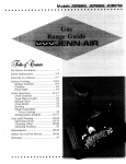
Gas Water Heater
Owners Manual
NOT FOR USE IN
MOBILE HOMES
N
FOR POTABLE WATER HEATING ONLY
NOT SUITABLE FOR SPACE HEATING
MODEl-
NUMBERS"
153333000
153,333030
I $3,333031
153333100
153.333130
153333131
153,333530
153.333531
30
30
30
40
40
40
50
50
Gal High Altitude
Gal.
GaL
Gal, High Altitude
Gal
Gal.
Gal
Gal,
G
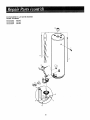
Installation
For
+ Operation
+ Repair Parts
ODORANT
ISADDED
TOTHE
CAS
Your Safe tv AN
usED
BYTHIS
W
ATER
.EATER
I
UJ
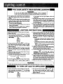
WARNING
WARNING:
If the information
in these
instructions are not followed exactly, a
fire or explosion may result, causin_ property damage, personal inJury or dea_ti.
-Do not store or use gasoline or other
flammab!e
vapors and liquid.s in the
vicinity of this or any other appliance.
-WHAT TO DO IF YOU SMELL GAS
Do not touch any
i not
Do not
try tophone
light
useany
Immediately
call
electrical switch; do
any
appliance.
in your
building.
your gas supplier
from a neighbor's phone. Follow the
I_as supplier s instructions.
• rf you can not reach your gas supplier,
call the fire department.
-Installation
and service must be performed by a qualified installer,
service
agency or the gas supplier.
Save this Manual
.._.__+!
for Future
- _+L,3_ .. --
Reference.
Improper
installation,
adjustment, alteratmn, service or maintenance
can cause
DEATH, SERIOUS BODILY INJURY, OR
PROPERTY DAMAGE. Refer to this manual for assistance or consult the local Sears
Service Center or gas utility for further
information.
currents
from
other
areas
of the struc-
..........
WARNING
Flammabl_e vapors
may be drawn by air t
ture t ° this appliance.
WARNING
READ THE GENERAL SAFETY SECTION
BEGINNING
ON INSIDE COVER AND
THEN THIS ENTIRE MANUAL
BEFORE
INSTALLING
OR OPERATING
THIS
WATER HEATER.
UJ
G
WARNING
Improper installation, adiustment0 alteration, service or maintenance can cause DEATH, SERIOUS BODILY INJURY, OR
PROPERTY DAMAGE_ Refer to this manual for assistance or
consult your local Sears Service Center for further information.
WARNING
At the time of manufacture this water heater was provided with
a combination temperature-pressure relief valve certified by a
nationally recognized testing laboratory that maintains periodic
inspection of production of listed equipment or materlars, as
meeting the requirements for Relief Valves and Automatic Gas
ShutoffDevices for Hot Water Supply Systems, and the latest
edition of ANSI Z21.22 and the code requirements of ASME. If
replaced, the valve must meet the requirements of local codes,
but not tess than a combination temperature and pressure relief
valve certified as meeting the requirements for Relief Valves
and Automatic Gas Shutoff Devices for Hot Water Supply
Systems,ANSI Z2t.22 by a nationally recognized testing laboratory that maintains periodic inspection of production o-flisted
equipment or materials.
The valve must be marked with a maximum set pressure not to
exceed the marked hydrostatic working pressure of the water
heater (150 Ibs_/sq. in.) and a discharge capacity not less than
the water heater input rate as shown on the model rating
plate. (Electric beaters - watts divided by 1000 x 3415 equal
BTU/Hr. rate.)
Your local jurisdictional authority, while mandating the use of a
temperature-pressure relief valve compiyin_ with ANSI Z21.22
and ASME, may require a valve model di_erent from the one
furnished with the water heater.
Compliance wilh such local requirements must be satisfied by
the installer or end user of the water heater with a locally prescribed temperature_pressure relief valve installed in the designated opening in the water heater in place of the factory furnished valve.
For safe operation of the water heater, the relief valve must not
be removed from it's designatedopening or plugged.
The temperature-pressure relief valve must be i-nstalleddirectly
into tee fitting of the water heater designated for the relief
valve. Position the valve downward and provide tubing so that
any discharge will exit only within 6 inches above, or at any
distance below the structural floor. Be certain that no contact
is made with any llve electrical part. The discharge opening
must not be blocked or reducedin size under any circumstances. Excessivelength, over 30 feet, or use of more than four
elbows can cause restriction and reduce the discharge capacity
of the valve.
No valve or other obstruction is to be placed between the
relief valve and the tank. Do not connect tubing directly to
discharge drain unlessa 6" air gap is provided. To prevent bodily injur-y, hazard to llfe, or prO)petty damage, therelief valve
must be allowed to discharge water in quantltles should circumstances demand. If the _]ischarge pipe is not connected to
a drain or other suitable means, the water flow may cause
property damage; ........
The Discharge Pipe:
--Must not be smaller in size than the outlet pipe size of the
valve, or have any reducing couplings or other r'estrictions°
--Must not be plugged or blocked.
--Must be of material listed for hot water distribution.
_Must be installed so as to allow complete drainage of both
the temperature-pressure relief valve, and the dlscbarge pipe.
--Must terminate at an adequate drain.
--Must not have any valve between the relief valve and tank.
WARNING
WATER HEATERSEQUIPPED FOR ONE TYPE GAS ONLY: This
water heater is equipped for one type gas only. Check lee model
rating plate near the gascontrol valve for the correct gas.DO NOT
USE THIS WATER HEATER WITH ANY GAS OTHER THAN THE
ONE SHOWN ON THE MODEL RATING PLATE.Failure to use the
correct gas can causeproblems which can result in DEATH, SERIOUS BODILY INJURY, OR PROPERTYDAMAGE. If you have any
questionsor doubtsconsultyour gassupplieror local utdlty.
WARNING
A fire can start if combustible
materialssuchas clothing, cleaning
materlals_
or flammableliquidsare placedagainstor next to the
waterheater.
WARNING
INSTALLATIONSIN AREASWHERE FLAMMABLELIQUIDS
(VAPORS)ARELIKELYTO BEPRESENT
OR STORED(GARAGES,
STORAGE,AND UTILITYAREAS,ETC):Flammablellquids (such
as gasoline,solvents,propane(LP)or butane,etc.), all of which
emitflammablevapors,maybe improperlystoredor usedin such
areas.The gaswaterheaterpdot fightor mainburnercan Ignite
such vapors,The resultingflashbackand fire can causedeathor
seriousburnsto anyonein thearea,aswellaspropertydamage.
If installation in suchareasis youronlyoption,thenthe installallon mustbe accomplished
in a way that thepilotflameandmain
burnerflameare elevatedfrom thefloor at least18 inches.While
this may reducethe changesof flammablevaporsfrom a floor
spill being ignited, gasoffneand other flammablesubstances
shouldnever-bestored or usedin the sameroomor areacontaining a gaswater heater or otheropenflame or sparkproducing
appliance.
I_OTE:Flammablevaporsmay be drawn by air currentsfrom
otherareasof thestructureto the appliance,
WARNING
HOTTER WATER CAN SCALD: Water heaters
areintendedtoproduce hotwater.Water heatedtoa temperature
which willsatisfy
clothes washing, dish washing, and other sanitizing needs can
scald and permanently injure you upon contact. Some people are
more likely to be permanently injured by hot water than others°
These include the elderly, children, the infirm, or physically/mentally handicapped. If anyone using hot water in your home fits
into one of these groups or if there is a local code or state Jaw
requiring a certain_temperaturewater at the hot water tap, then
you must lake special precautions. In addition to usingthe lowest
possibletemperature settin_ that satisfiesyour hot water needs,
some type of tempering dewce, suchas a mixing valve, shouldbe
used at the hot water taps used by these people or at the water
heater. Mixing valves are available at plumbing supply or hardware stores, l_ollow manufacturersinstructions-for installation of
the valves.Before changingthe factory setting on the thermostat,
read the "Temperature Regulation" section in thismanual.
WARNING
BEFORE LIGHTING [PROPANE (L,R)GAS WATER HEATER5]:
Propane (LR) gasis heavier than air. Should there be a leak in the
system, the gas will settle near the ground. Basements, crawl
spaces,skirted areas under mobile homes(even when ventilated),
c|osetsand areasbelow ground level will serve as pocketsfor the
accumulation of this gas. Before attempting to light or religbt the
water heater'spilot or turning on a nearbyetectrlcal light switch,
be absolutelysure there is no accumulatedgas in the area° Search
for odor ofgas by sniffing at ground level in the vicinity of the
apphance. If-odor is detected, follow stepsindicated at "For Your
Safety" on the cover pageof thismanual then leave the premises.
WARNING
Thiswaterheater
must
not be installed directly on carpeting.
Carpetin_ must be protected by a metal or woodpanel beneatl_
the appliance extendin_ beyond the full width and depth of the
appliance by at ieast 3 inches (76.2mm) in any direction, or if the
appliance is installed in an alcove or closet,the entire floor must
be covered by the panel. Failure to heed thiswarning may result
in a fire hazard.
WARNING
A gas water heater cannot operate properly without the correct
amount of air for combustion°Do not install in a confined area
suchas a closet, unless_ou provide air as shownin the "Locating
TEe New Water Heater section°Never obstruct the flow of ventilation air. If you have any doubts or questionsat all, call your
gas company_Failure to provide the proper amount of combustion air can result in a fire or explosionand can cause DEATH,
SERIOUS BODILY INJURY, OR PROPERTYDAMAGE.
WARNING
If this water heater will be used in beauty shops, barber shops,
cleanln_ establishments,or self-service laundries with dry cleaning equipment, it is imperative that lhe water heater or water
heaters be installed so that combustion and ventilation air be
taken from ouLsidethese areas. Refer to the "Locating The New
Water Heater" section of this manual and also the latest edition of
the National Fuel Gas Code, ANSI Z223.t, also referred to as
NFPA 54 for specificsprovided concerningair required.
WARNING
VENT DAMPERS - Any vent damper, whether it is operated thermally or otherwise must be removed if its use inhibits proper
drafting of the water heater.
Thermally Operated Vent Dampers: Gas-fired water heaters having thermal efficiency in excessof B0% may produce a relatively
low flue gas temperature. Such temperatures may not be high
enough to properly open thermally operated vent dampers. Tl_is
woula causespillage of flue gasesandmay cause carbon monoxide poisoning.
Vent dampers must bear evidence of certification as complying
with the |atest edition of American National Standard ANSI
Z21.68 (ANSI Z21.66 & 67, respectively,cover electrically and
mechanically actuated vent dampers)°Before installation of any
vent damper, consult your local SearsService Center or the gas
utitity for further information°
WARNING
I. The appliance and its individual shutoff valve must be disconnected from the gas supply piping systemduring any pressure
testing of the gas system at test pressures in excess of '/_
pound-per square inch (3_5kPa).
2. The appliance must he isolatedfrom the gas supplypiping system by closing its individual manual shutoff valve during any
pressure testing of the gas supply piping system at tesl pressuresequaSor lessthan '/2poundper squareinch (3_5kPa).
WARNING
SOotbuitd_i_pindicatesa pi-0blem that requires correction before
sooting can result in a fire or explosion causing DEATH, SERIOUS BODILY INJURY, OR PROPERTYDAMAGE_
WARNING
The water heater with draft hood installed must be properly
vented to a chimney which terminates outdoors. Never operate
the water heater unlessit is vented to the outdoors and has adequate air supply to avoid risks of improper operation, explosion
or asphyxiatlon_
WARNING
Obstructed or deteriorated vent systems may present a serious
heatth riskor asphyxiation.
WARNING
Chemical vapor corrosionof the flue and vent systemmay occur
if air for combustioncontainscertain chemical vapors°Spray can
propellants, cleaning solvents, refrigerator and air conditioner
refrigerants, swimming pool cheml'cals, calcium and sodium
chloride, waxes, bleach, and process chemicalsare typical compounds which are potentlally corrosive°
WARNING
Minimum clearancesbetween the water heater and combustible
construction are 1" at the sidesand rear, 4" at the front, and 6"
from the vent pipe. Clearance from the top of the jacket is 18"
on most models. Note that a lesser dimension may be allowed
on some models.Gas water heaters acceptable for use on combustible floors in an alcove or closeL Refer to the label on the
water heater adjacent to the gascontrol vaive for ali clearances.
WARNING
HYDROGEN GAS: Hydrogengas can be produced in a hot water
systemthat has not been used for a long period of time (generally
two weeks or more). Hydrogen gas is extremely flammable and
explosive_To prevent the possibilityof injury under these conditions, we recommendthe hot water faucet be opened for several
minutes at the kitchen sink beforeany electrical appliances which
are connected to the hot water system are used (such as a dishwasheror washingmachine). If hydrogengasis present, there will
probably be an unusual sound similar to air escapingthrough the
pipe as the hot water faucet is opened. There must be no smoking
or open flame near the faucetat the time it is open°
WARNING
INSULATING JACKETS:When installing an external water heater
insulation jacket on a gaswater heater:
a_ DO NOT coverthe temperature-pressure relief valve°
b. DO NOT put insulation over any part of the top of the gas
water heater.
c. DO NOT put insulation over the gas control valve or gas control valve/burner cover,or any access areas to the burner.
d. DO NOT let insulation around the gas water heater to get
within 8 inchesof the floor (air must get to the burner).
e. DO NOT cover or remove operating instructions, and safety
related warning labels and materials affixed to the water
heater.
Failure to heed this will result in the possibility of a fire or
explosion.
WARNING
Do not use this appliance if any part of it has been under water.
Immediately call a SearsServiceTechnician to insp.ecttee appliance and to replace the gas control or any part of the burner system which hasbeen under water.
CAUTION
WATER HEATERSEVENTUALLY LEAK:Installation of the water
heater must be accomplished in such a re;inner lhat if tEi_tank Or
any connections should leak, the flow of water will not cause
damage to the structure. When such locations cannot be avoided, a suitable drain pan should be installed under the water
heater. Drain pansare available at your local Searsstore. Such a
drain pan must be not greater than 1'/_inches deep: have a minimum length and width of at least2 inchesgreater than the water
heater dimensionsand must be piped to an adequate drain° The
pan must not restrict combustion air flow. Under no circumstances is the manufacturer or Sears to be hetd liable for any
water damagein connection with this water heater.
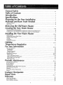
General Safety ..............................................................................................
2_3
Table of Contents ...............................................................................................
4
Introduction ........................................................................................................
s
Specifications .....................................................................................................
s
Preparing for the New Installation ..............................................................
5
Materials and Basic Tools Needed ................................................................
6
Materials Needed .......................................................................................................................................................................................
6
Basic Tools ...................................................................................................................................................................................................
6
Removing the Old Water Heater ..................................................................
z
Locating the New Water Heater ...................................................................
8-9
Facts to Consider About Location .............................................................................................................................................................
8
Combustion Air and Ventilation for Appliances Located in Unconfined Spaces .........................................................................
9
Combustion Air and Ventilation for Appliances Located in Confined Spaces ...........................................................................
9
Filling the Water Heater ......................................................................................................................................................................................
12
Venting ........................................................................................................................................................................................................
12
Gas Piping .............................................................................................................................................................................................
13
Installation Checklist ..........................................................................................................................................................................
14
L
Ign[Ing .........................................................................................................................
_s-16
0
I1"
,r o
Temperature Regulation ..................................................................................
_z
For Your Information ........................................................................................
_8.19
Start Up Conditions .....................................................................................................................................................................
18
Condensat on ......................................................................................................................................................................................................
18
Smoke/Odor ..........................................................................................................................................................................................
18
Thermal Expansion ...............................................................................................................................................................................
18
Strange Sounds ...................................................................................................................................................................................
18
Operational Conditions ..................................................................................................................................................................
18-19
Smelly Water ........................................................................................................................................................................................
18-19
"Air" In Hot Water Faucets ..............................................................................................................................................................
19
High Temperature Shut Off System ..................................................................................................................................................
19
Not Enough or No Hot Water .................................................................................................................................................................
19
Water Is Too Hot ................................................................................................................................................................................
19
Periodic Maintenance .......................................................................................
2o-2_
Venting System Inspection ...........................................................................................................................................................................
20
Burner Inspection ...............................................................................................................................................................
20
Burner Cleaning ........................................................................
20
Housekeeping ..........................................................................................................................................................................................
20
Temperature-Pressure Relief Valve Operation .....................................................................................................................................
21
Tank (Sed ment) C eaning .........................................................................................................................................................
21
Draining ...........................................
L., ,,,,,Z.......................
:................................................................................................ 21
Dra n Va ve Washer Rep acement .....................................................................................................................................................
21
Service ......................................................................................................................................................................................................
21
Warranty ...............................................................................................................
28
About Your Warranty ........................................................................................................................................................28
SearsInstallation Policy .....................................................................................................................................
28
SearsInstallation Warranty ..........................................................................................................................................................
28
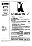
WARNING
Thank You forpurchasing
aSears
waterheater,
This gas-fired water heater is design certified by the
American Gas Association Laboratories under
American National Standards for Gas Water Heaters.
The installation must conform with this manual, Local
Codes and with the latest edition of ithe National Fuel
Gas Code, ANSI Z223.1.
This publication is available from ygur local government or public library, gas company, or by writing
NFPA, Batterymarch ParkpQuincy, MA 02269.
Properly installed and maintained, it should give you yearsof
trouble freeservice. If you should decide that you want the new
water heater professionally installed by Searscontact the local
SearsService Center or any Searsstore, They will arrange for
prompt, quality installation by Searsauthorized contractors_
Abbreviations Found in This Instruction Manual
A_G.A. - American Gas Association
AN.S.I. - American National Standards Institute
N F PAo - National Fire Protection Association
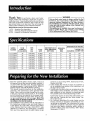
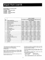
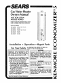
MODEL
NUMBER
TANK
CAPACITY
IN GALLONS
TYPE
OF
GAS
153.333000
30
153.333030
153.333031
3O
NATURAL
NATURAL
'N'ATURAL
153.333100
40
153.333130
40
40
153.333131
3O
is3.33353b
.........50
50
NATURAL
32,000
32,00O
32,000
1 Read the "General Safety" section, pages 2 and 3 of
this manual first and then the entire manual carefully.. If
you don't follow the safety rules, the water heater will
not operate properly. It could cause DEATH, SERIOUS
BODILY INJURY AND/OR PROPERTYDAMAGE,
This manual contains instructions for the installation,
operation, and maintenance of the gas-fired water
heater.,it also contains warnings through out the manual that you must read and be aware of, All warnings
and all instructions are essential to the proper operation of the water heater and your safety. Since we cannot put everything on the first few pages, READ THE
ENTIRE MANUAL BEFOREATTEMPTING TO INSTALL
OR OPERATETHE WATER HEATER.
2. The installation must conform with the instructions in
this manual; gas company rules; and Local Codes, or
in the absence of Local Codes, with the latest edition
of the National Fuel Gas code, ANSI Z223_I, also
referred to as NFPA 54. This publication is available
from your local government or public library or gas
MINIMUM
VENT
PIPE
DIMENSIONS
IN INCHES
DIAMETER
HEIGHT TO
JACKETTOP
31.0
3"
16"
31.0
31.0
3"
3';_
......
16"
16"
33.0
3"
18"
56%"
33.0
3"
3"
18"
18"
56V_"
33.0
[
33.0
3"
[
33.0
3"
20"
56VI"
30,000
30,000
30,000
NATURAL
32,000
NATURAi_...........
32,O00
NATURAL
NATURAL
153.333531
B.T.U.
RATE
RECOVERY RATE
GALS. PER HOUR
@90°F RISE
company
or by writing
NFPA,
56"
56"
56"
56 Y_"
56'1,"
Batterymarch
Park,
Quincy, MA 02269.
3, If after reading this manual you have any questions or
do not understand any portion of the instructions, call
the Sears Service Center
4. Carefully plan the place where you are going to put the
water heater. Correct combustion, vent action, and vent
pipe installation are very important in preventing death
from possible carbon monoxide poisoning and fires
Examine the location to ensure the water heater complies with the "Locating the New Water Heater" section in this manual
5. For California installation this water heater must be
braced, anchored, or strapped to avoid falling or moving during an earthquake, See instructions for correct
installation procedures,. Instructions may be obtained
from your local dealer, wholesaler, public utilities or
California Office of the State Architect, 400 P Street,
Sacramento, CA 95814,
Materials
/
Needed
\
To simplify the installation Searshas available the installation parts shown below_ You may or may not need all of
these materials, depending on your type of installation
WATER HEATER STAND 24"x24"x1B"
FOR USEWITH WATER HEATERS INSTALLED
IN RESIDENTIAL GARAGES HAVING A DIAMETER24" OR LESSAND A RATED CAPACITY
75 GALLONS OR LESS
I
COMPRESSION COUPLINGS
Comprel_n
FOR CONNECTING TO
COPPER PLUMBING WITHOUT SWEAT SOLDERING
EXPANSION TANKS FOR
THERMAL EXPANSION
CONDITIONS AVAILABLE
IN 2 GALLON AND .5
GALLON CAPACITY
THROUGH LOCAL SEARS
SERVICE CENTERES
O
VENT ELBOW
WATER HEATER
INSTALLATION KIT WITH
FLEXIBLE CONNECTORS FOR
3/4" GALVANIZED OR
I/2"COPPER PLUMBING
VENT EXTENSION
FLEXIBLEWATER
HEATER GAS CONNECTOR WITH
FITTINGS
Willr
Hil
_IltlEI
I
*l'llJ_l
WATER HEATER HEAT TRAPS
HELP REDUCE HEAT LOSS DUE
TO THERMAL SYPHONING
DRAIN PANS
AVAILABLE IN 20" DIAMETER FOR
WATER HEATERSHAVING A DIAMETER 18"
OR LESSAND AVAILABLE IN 28" DIAMETER
FOR WATER HEATERS HAVING A DIAMETER
26" OR LESS
Basic Tools
You may or may not need all of these tools, depending on
your type of installation,,
your local Sears store
Pipe Wrenches (2)
These
tools
can
be purchased
14"
Screwdriver
Tin Snips
6 Foot Tape
Garden Hose
of Folding
Rule
Drill
Pipe dope or Teflon Tape
at
ADDITIONAL
TOOLS NEEDED
WHEN SWEAT SOLDERING
Tubing Cutters or Hacksaw
Propane Torch
Soft Solder
Solder Flux
Emery_ Cloth
Wire Brushes
HACKSAW
GARDEN
HOSE
6 FOOT TAPE
PIPE
WRENCH
3/4" WIRE BRUSH
SLOT-HEAD SCREWDRIVER
I/2" WIRE BRUSH
PHILLIPS SCREWDRIVER
PROPANE
TIN SNIPS
ROLL OF TEFLON TAPE
(USE ONLY ON WATER
TORCH
ROLL OF LEAD FrEE
SOFT SOLDER
CONNECTIONS)
PIPE DOPE (SQUEEZE TUBE)
(USE FOR WATER AND GAS CONNECTIONS)
ROLL OF EMERY
CLOTH
SOLDER FLUX
TUBING CUTTER
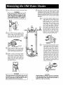
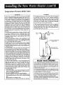
OTurn
ItOFF
_"
the gas supply to the water heater.
WARNING
Q
I
If the main gas line shutoff valve serving all gas appliances is used, also shut
"OFF" the gas at each appliance. Leave
all gas appfiances shut aOFF" until the
water heater installation is completed.
I
I
I
I
_.J
Q
®
®
the water supply to the
Turn
water heater at the water shut off
valve or water meter Some installations require that the water be
turned off to the entire house
t_O
Q
FFtt
Q
Q
a, If you have copper piping to the
water heater, the two copper water
pipes can be cut with a hacksaw
approximately
four inches away
from where they connect to the
water heater. This will avoid cutting
off the pipes too short. Additional
cuts can be made later if necessary
sure relief valve
Disconnect
the temperature-presdrain line, When
the water heater is drained, disconnect the hose from the drain valve.
Close the drain valve The water
heater is now completely disconnected and ready to be removed.
®
Check again to make sure the gas
supply is "OFF" to the water heater,
Then disconnect the gas supply connection from the gas control valve,,
Attach a hose to the water heater
drain valve and put the other end in
a floor drain or outdoors Open the
water heater drain valve° Open a
nearby hot water faucet which will
relieve pressure in the water heater
and speed draining.
i,
Disconnect the vent pipe from the draft hood
where they connect to the water heater. In most
installations the vent pipe can be lifted off after
any screw or other attached devices are removed
Dispose of the draft hood,'The new water heater
has the draft hood which must be used for proper
operation,
WARNING
The water passingout of the drain valve may be
extremely hot. To avoid being scalded, make
sure all connections are tight and that the water
flow is directed away from any person.
b, If you have galvanized pipe to the
water heater, loosen the two galvanized pipes with a pipe wrench at
the union in each line. Also disconnect the piping remaining to
the water heater. These pieces
should be saved since they may be
needed when reconnecting
the
new water heater. Disconnect the
temperature-pressure relief valve
drain line When the water heater
is drained, disconnect the hose
from the drain valve. Close the
drain valve The water heater is
now completely disconnected and
ready to be removed,
CAUTION
Mineral buildup or sediment may have accumulated
in the old water heater. This causesthe water heater
to be much heavier than normal and this residue, if
spilled out, could causestaining.
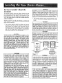
Facts to Consider About the
Location
You should carefully
choose an indoor location for the
new water heater, because the placement is a very important consideration
for the safety of the occupants in the
building and for the most economical
use of the appliance This water heater is not for use in mobile homes or
outdoor installation.
Whether
replacing
an old water
water heater in a new location,
points must be observed,
I
heater or putting the
the following
critical
The location selected should be indoors as close as
practical
to the gas vent or chimney
to which
the
water heater vent is going to be connected,
and as
centralized
with the water piping system as possible
The water heater, as all water heaters, will eventually
leak Do not install without adequate drainage provisions where water flow will cause damage
WARNING
Propellants of aerosol sprays and volatile compounds,
(cleaners, chlorine based chemicals, refrigerants, etc_) in
addition to being highly flammable in many cases, wilt
also changeto corrosivehydrochloric acid when exposed
to the combustion products of the water heater_ The
resultscanbe hazardous,and also causeproduct failure.
2 The location selection
must provide adequate dearances for servicing and proper operation of the water
heater
WARNING
This water heater must not be installed directly on carpeting. Carpeting must be protected by a metal or wood panel
beneath the appliance extending beyond the full width and
depth of the appliance by at least 3 inches (76.2mm) in
any direction, or if the appliance is installed in an alcove
or closet, the entire floor must be covered by the panel.
Failure to heed this warning may result in a fire hazard.
WARNING
CAUTION
WATER HEATERS EVENTUALLY LEAK: Installation
of the
water heater must be accomplished
in such a manner
that if the tank or any connections should leak, the flow
of water will not cause damage to the structure. When
such locations
cannot be avoided, a suitable drain pan
should be installed under the water heater° Drain pans
are available at your local Sears store. Such a drain pan
must be not greMer than lY_ inches deep, have a minimum length and width of at least 2 inches greater than
the water heater dimensions and must be piped to an
adequate drain. The pan must not restrict combustion air
flow. Under no circumstances is the manufacturer
or
Sears to be held liable for any water damage in connection with this water heater.
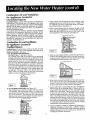
Minimum clearances between the water heater and combustible construction are i '_at the sides and rear, 4" at the
front, and 6" from the vent pipe. Clearance from the top of the
jackel is 18" on most models. Note that a lesser dimensmn may
be allowed on some models° Gas water heaters acceptable for
use on combustible floors in an alcove or closet° Refer to the
label on the water heater adjacent to the gas control valve for
all clearances.
t 2" MAX.
6" MIN
t
VENTILATION
AIR
4" MIN
OPENINGS
U
÷
÷
6" M I"_<
1" MIN
TOPVIEW
OF
CLOSET
WITHOUT DOOR
lIT" MAX
FRONT
TOPVIEW'I" MIN
OF CLOSET
WITH
DOOR
VIEW
OF DOOR
R_CTANGULAR
_'
WARNING
INSTALLATIONS IN AREAS WHERE FLAMMABLE LIQUIDS
(VAPORS) ARE LIKELY TO BE PRESENT OR STORED
(GARAGES, STORAGE AND UTILITY AREAS, ETC):
Flammable liquids (such as gasoline, solvents, propane (LP)
or butane, etc.) or other substances (such as adhesives,
etc.), all of which emit flammable vapors, may be improperly stored or used in such areas. The gas water heater pilot
I!ght or main burner can ignite such vapors. The resulting
flashback and fire can cause death or serious burns to any_
one in the area, as well as property damager
If installation in such are'as is your only option, then the
installation must be accomplished in a way teat the pilot
flame and main burner flame are elevated from the floor at
least 18 inches. While this may reduce the changes of
flammable vapors from a floor spill being ignited, gasoline
and other flammable substances should never be stored or
used in the same room or area containing a gas water
heater or other open flame or spark producing appliance.
Also, the water heater must be located and/(}r protected so
it is not subject to physical damage by a moving vehicle.
NOTE: Flammable vapors may-be drawn by air currents
from other areas of the structure to the appliance°
Figure t ]
AIR DUCT
WARNING
A gas water heater cannot operate properly without the
correct amount of air for combustion° Do not install in a
confined area such as a closet, unless you provide air as
shown in Figures 1-5. Never obstruct the flow of ventilation air. If you have any doubts or questions at all, call
your_as company or Sears Service Center. Failure to
provide the proper amount of combustion air can result
m a fire or explosion and can cause DEATH, SERIOUS
BODILY INJURY, OR PROPERTY DAMAGE.
WARNING
If this water heater will he used in beauty shops, barber
shops, cleaning establishments, or self-service laundries
with dry cleaning equipment, it is imperative that the
water heater or water heaters be installedso that combustion and ventilation air be taken from outside theseareas.
Refer 1o the "LocatingTbe New Water Heater" sectionof
this manualand also the latestedition of the National Fuel
Gas Code, ANSI Z223_1, also referred to as NFPA 54 for
specifics providedconcerningair required.
Combustion Air and Ventilation
for Appliances Located in
Unconfined Spaces
Unco_,fined Space is a space whose volume is not Jessthan 50
cubic feet per 1,000 Btu per hour of the aggregateinput rating
of all appliances installed in that space_Roomscommunicating
directly with the space in which the appliances are installed,
through openings not furnished with doors, are considered a
part of the unconfined space
In unconfined spacesin buildings, infiltration may be adequate
to provide air for combustion, ventilation and dilution of flue
gases,However, in buildings of tight construction (for example,
weather stripping, heavily insulated, cau]ked, vapor barrier,
etc.) additional air may need to be provided using the methods
described in Combustion Air and Ventilation for App lances
Located in Confined Spaces,b
]. When directly communicating with the outdoors, each
opening shah have a minimum free area of t square inch
per 4,000 BTU per hour of total input rating of all equipment in the enclosure tSeeFigure 3.)
2. When communicating with the outdoors through vertical
ducts, each opening shall have a minimum free area of 1
square inch per 4,000 BTU per hour of total input rating
of all equipment in the enclosure (See Figure 43
Combustion Air and Ventilation
for Appl nces Located in
Confined Spaces
Confined Space is a space whose volume is less than 50 cubic
feet,per 1,000 Btuper hour of the aggregateinput rating of all
appliances installedin that space,
a. ALLAIR FROM INSIDE BUILDINGS:
(SeePageg Figure 1, and Figure 2 below)
The confined space shall be provided with two permanent
openingscommunicating directly with an additional room(s)
of sufficient volume so that the combined volume of all
spacesmeets the criteria for an unconfined space The total
input of all gas utilization equipment installed in the combined space shall be considered in making this determination. Each opening shall have a minimum free area of one
squareinch per 1,000 8TU per hour of the total input rating
of a!l gas utilization equipment in the confined space, but
not less than I00 square inches. One opening shall commence within 12 inches of the top and one commencing
within 12 inches of the bottom of the enclosure
TER
Figure 4 t
t
!
,.l
3. When communicating with the outdoors through horizontal ducts, each opening shall have a minimum free area of
I square inch per 2,000 13TUper hour of total input rating
of all equipment in the enclosure (See Figure 5.)
!1!
" -tP
I Figure 5 J
i---7
FUN
OPEN{_IGS
b. ALLAIR FROMOUTDOORS: (see Figures 3-51
The confined space shall be provided with two permanent openings, one commencing within 12 inches of the
top and one commencing within 12 inches from the bottom of the enclosure. The openings shall communicate
directly, or by ducts, with the outdoors or spaces(crawl or
attic) that freely communicate with the outdoors..
4, When ducts are used, they shall be of the same cross-sectional area as the free area of the openings to _vhich they
connect. The minimum short side dimension of rectangular
air ducts shall not be less than 3 inches (SeeFigure 5.)
5,. Louvers and Grilles: In calculating free area, consideration
shall be given to the blocking effect of louvers, grilles or
screens protecting openings. Screens used shall not be
smaller than % inch mesh If the free area through a design
of louver or grille is known, it should be used in calculatingthe size opening required to provide the free area specified,. If the-design and free area is not known, it may be
assumedthat wood louvers will be 20-25 percent free area
and meta] louvers and grilles will have 60-75 percent free
area. Louvers and grilles shall be fixed in the open position
or interlocked with the equipment so that they are opened
automatically during equipment operation.
6 Special Conditions Created by Mechanical Exhausting or
Fireplaces: Operation of exhaust fans, ventilation systems,
clothes dryers or fireplaces may create conditions requiring
special attention to avoid unsatisfactory operation of
installed gas utilization equipment.
Figure 3 i
ALT
IIILET _R
VEh'_qL&T_O,b_
I*OUV'_q5
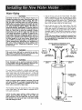
Water Piping
HOTTER
WARNING
WATER CAN SCALD: Water heaters are
14
intended to produce hot water. Water heated to a temperature whmchwill satisfy clothes washing, dish washing, and other sanitizing nei_dscan scaldand permanently inlure you upon contact. Some people are more
likely to be permanently injured by hot water than others. These include the elderly, children, the infirm, or
physically/mentally handicapped, if anyone uslng hot
water in your home fits into one of these groups or if
there is a local code or state law requiring a certain
temperature water at the hot water tap, then you must
take special precautions. In addition to using the lowest possible temperature setting that satisfies your hot
water needs, some type of tempering device, such as a
mixing valve, should he used at the hot water taps used
by these people or at the water heater. Mixing valves
are available at plumbing supply or hardware stores.
Follow manufacturers instructions for installation of
the valves. Before changing the factory setting on the
thermostat, read the "Temperature Regulation" section
in this manual.
2"
Look at the top cover of the water heater..The water
outlet is marked hot. Put two or three turns of teflon
tape around the threaded end of the threaded-to-sweat
coupling and around both ends of the ¥_"threaded nipple, Using flexible connectors, connect the hot water
pipe to the hot water outlet on the water heater°
Look at the top cover of the water heater. The cold
water inlet is marked coid_ Put two or three turns of
teflon tape around the threaded end of the threadedto-sweat coupling and around both ends of the ¥4"
threaded nipple_ Using flexible connectors, connect
the cold water pipe to the cold water inlet of the water
heater.
NOTE: This water heater is insulated to minimize heat
loss from the tank. Further reduction in heat loss can
be accomplished by insulating the hot water lines
from the water heater.
INSTALLATION
COMPLETED
USING
SEARSINSTALLATION KIT
SHUTOFF
FLEXIBLEWATER
VALVE
CONN
-WARNING
This water heater shall not be connected to any heating systems or component(s) now or previously used
wlth a non-potable water heating appliance.
HOT OUTLET
TO HOUSE
COLD INLET
WATER LINE
THRFADED TO
SWEAT COUPLING
THREADED
TO
SWEAT COUPLING
WARNING o
Toxic chemicals such as used for treatment of boilers
or non-potable water heating appliances shall never be
introduced into a potable water heating system.
NIPPLE
NIPPLE
COLD
If a water heater is installed in a Closed water supply system; such as one having a back-flow preventer, check
valve, water meter with a check valve, etc..., in the cold
water supply; means shall be provided to control thermal
expansion. Contact the local utility or local Sears Service
Center on how to control this situation.
It_
NOTE: To protect a_ainst untimely corrosion of hot and
cold water fittings, zt is strongly recommended that dielectric unions or couplings 5e installed on this water
heater when connected to copper pipe,
The illustration shows the attachment
to the water heater, The water heater
inch water connections,
of the water piping
is equipped with ¾
NOTE: If using copper tubing, solder tubing to an
adapter before attachJ_ng the adaptor to the colit water
inlet connection. Do not solder the cold water supply
line directly to the cold water inlet. It will harm the dip
tube and damage the tank.
10
VALVE
Temperature-Pressure
Relief Valve
WARNING
WARNING
At the time of manufacture this water heater was provided
with a combination temperature-pressure relief valve certified by a nationally recognized testing laboratory that maintains periodic inspection of production
of listed equipment
or materials_ as meeting the requirements for Relief Valves
and Automatic Gas Shutoff Devices for Hot Water Supply
Systems, and the latest edition of ANS1 Z21.22 and the code
requirements
of ASME If replaced, the valve must meet the
requirements of local codes, but not less than a combination
temperature and pressure relief valve certified as meeting
the requirements
for Relief Valves and Automatic
Gas
Shutoff Devices for Hot Water SupplySystems, ANSI Z21.22
by a nationally recognized testinglaboratory
that maintains
periodic inspection
of production
of listed equipment
or
materials°
The valve must be marked with a maximum set pressure not
to exceed the marked hydrostatic
working pressure of the
water heater (150 Ibs.!sq_ in°) and a discharge capacity not
less than the water heater input rate as shown on the model
rating plate. (Electric heaters - watts divided by 1000 x 3415
equal BTU/Hr. rate.)
.,
Your local jurisdictional
authority, while mandating me use
of a temperature-pressure
relief valve complying with ANSI
Z21.22 and ASME, may require a valve model dl_fferent from
the one furnished with the water heater,
ampliance with such local requirements must be satisfied
the installer or end user of the water heater with a locally
'escribed temperature-pressure
relief valve installed in the
tesignated opening in the water heater in place of the facto'y furnished valve.
:or safe operation of the water heater, the relief valve must
not be removed from it's designated opening or plug.ged.
The temperature-pressure
relief valve must be Installed
directly into the fittingof the water heater designated for the
relief valve. Position the valve downward and provide tubing
so thal any discharge will exit only within 6 inches above, or
at any distance below the structural floor. Be certain that no
contact is made with any live electrical part. The discharge
opening must not be blocked or reduced in size under any
circumstances. Excessive length, over 30 feet, or use of more
than four elbows can cause restriction and reduce the discharge capacity of the valve.
No valve or other obstruction is to be placed between the
relief valve and the tank. Do not connect tubing directly to
discharge drain unless a 6" air gap is provided. To prevent
bodily Injury, hazard to life, or property damage, the relief
valve must be allowed to discharge water in quantities
should circumstances demand_ If the discharge pipe is not
connected to a drain or other suitable means, t_hewater flow
may cause property damage .........
The Discharge Pipe:
--Must not Ge smaller in size than the outlet pipe size of the
valve, or have any reducing couplings or other restriction.
--Must not be plugged or blocked°
--Must be of material listed for hot water distribution°
--Must be installed so as to allow complete drainage of both
the temperature-pressure relief valve, and the discharge
plpe.
_Must terminate at an adequate drain.
--Musl not have any valve between the relief valve and tank°
The temperature-pressure relief valve must be manually operated at least once a year, Caution should be
taken to ensure that (I) no one is in front of or around
the outlet of the temperature-pressure
relief valve discharge line, and (2) t_e water manually discharged will
not cause any bodily
injury or property
damage
because the water may be extremely hot,
If after manually operating the valve, it fails to completely reset and continues
to release water, immediately
close the cold water inlet to the water heater, follow the
draining instructions, and replace the temperature-pressure relief valve with a new one°
HOT
SHUTOFF
VALVE
COLD
RE-PRESSURE
RELIEF VALVE
HARGE PIPE
(Do not cap or plug)
[]
6" AIR GAP
FLOOR
DRAIN
RELIEF VALVE OPENING
ATTHETIMEOF MANUFACTURE,
THISWATERHEATERWASPROVIDED
WITHACOMBINATION
TEMPERATURE-PRESSURE
REUE_:VALVELISTED
AS COMPLYING
WITHTHESTANDARD
FORRELIEFVALVESANDAUTOMATICGASSHUTOFFDEVICESFORHOT WATERSUPPLYSYSTEMS,
ANSIZ21 22. FORSAFE OPERATIONOF THE WATERHEATER,THE
RELIEFVALVEMUSTNOTBE REMOVED
FROMITSDESIGNATED
POINT
OF INSTALLATION
OR PLUGGED
YOURLOCALJURISDICTIONAL
AUTHORITY,
WHILEMANDATING
THEUSE
OF A TEMPERATURE,PRESSURE
RELIEFVALVECOMPLYING
WITHANS!
Z21.22ANDASME,MAYREQUIREA VALVEMODELDIFFERENTFROM
THEONEFURNISHED
WITHTHEWATERHEATER
COMPLIANCE
WITHSUCHLOCALREQUIREMENTS
MUSTBESATISFIED
BY THE INSTALLEROR ENDUSEROF THE WATERHEATERWITHA
LOCALLY PRESCRIBEDTEMPERATURE-PRESSURE
RELIEFVALVE
INSTALLED
IN THEDESIGNATED
OPENINGINTHEWATERHEATER,
SEEMANUALHEADING--"TEMPERATURE,
PRESSURERELIEFVALVES"
FORINSTALLATION
ANDMAINTENANCE
OF RELIEFVALVE,DISCHARGE
PIPEANDOTHERSAFETYPRECAUTIONS
1I
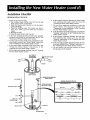
14Place the draft hood legs in the receiving holes on the
top of the water heater,,The legs will snap in the holes
to give a tight fit.
2, Place the vent pipe over the draft hood, With the vent
pipe in position, drill a small hole through both the
vent pipe and draft hood Secure them together with a
sheet metal screw,
Filling the Water Heater
CAUTION
Never use this water heater unlessit is completely filled
with water. To prevent damage to the tank, the tank must
be filled with water_Water must flow from the hot water
faucet before turning "ON" gas to the water heater.
To fill the water heater with water:
1, Close the water heater drain valve by turning the handle to the right (clockwise) The drain valve is on the
lower front of the water heater.,
2 Open the cold water supply valve to the water heater
NOTE: The cold water supply valve must be left open
when the water heater is m use.
3, To insure complete filling of the tank, allow air to exit
by opening the nearest hot water faucet.. Allow water
to run untila constant flow is obtained., This will let air
out of the water heater and the piping.
4. Check all new water piping for leaks° Repair as needed,
DRAFTHOOD
",_
_
[VENT,_I
_
S_RE_"_
[ €
DRAFT HOOD
_._VENT TO OUTDOORS
DRAFT HpO'D._
-OR ,_HIMNEY
'
-WARNING
!
The water heater with draft hoodinstalledmusthe connect-[
ed to a chimneywhich terminatesto the outdoors°Never I
operatethe water heater unlessit is vented to the outdoorsI
I and hasadequateair supply to avoid risksof improperopera- [
[ tion, explosionor asphyxiation.
J
Venting
WARNING
VENT DAMPERS - Any vent damper, whether it is ol_erated
thermally or otherwise must be removed if its use Inhibits
proper drafting of the water heater.
Thermally Operated Vent Dampers: Gas-fired water heaters
having thermal efficiency in excess of 80% may produce a
relatively low flue Rastemperature. Such temperatures may.
not be high enough to properly open thermally operated
vent dampers. Thm_s
would cause spillage of flue gases and
may cause carbon monoxide poisoning.
Vent dampers must bear evidence of-certification as complying width the latest edition of the American National
Standard ANSI Z21.68 (ANSI Z21_66 & 67, respectively,
cover electrically and mechanically actuated vent dampers).
Before installation of any vent damper, consult the local
Sears Service Center or gas utility for further information.
......
WARNING
The ventpipe from the water heatermust be no lessthan the
I diameterof thedraft hoodoutlet on thewaterheater,and must
Lslopeupwardto thechimneyat least '1,inchper linear foot.
All vent gases must be completely vented to the outdoors
of the structure (dwelling), Install only the draft hood provided with the new water heater and no other draft hood
Vent pipes must be secured at each joint with sheet metal
screws_
,o
CHIMNEY
PER LINEAR FOOT
--WARNING
I
VENTPIPEINSTALLATION
To insure properventing of this gas-firedwater heater,the
correctventp=_pe
diametermustbe utilized_Any additions or
deletionsof othergasapplianceson a commonventwith this
water heatermay adversely affect the operationof the water
heater_Consultthe localSearsServiceCenteror gasutility if
anysuchchangesare planned.
There must be a minimum of6"clearance between single wall
vent pipe and any combustible material Fill and sealany clearance between single wall vent pipe and combustible material
with mortar mix, cement, or other noncombustible substance
Forother than singlewall, follow vent pipe manufacturer'sclearance specifications Toinsurea tight fitof the vent pipe in a brick
chimney, sealaround the vent pipe with mortar mix cement
_or proper venting in certain installations, a larger diameter
vent pipe may be necessary. Due to great variances in
installations, unforeseeable by the manufacturer of the
water heater, you must consult your gas company to aid
you in determining the proper venting, for your.water heater.
from the vent tables in the latest edition of the National Fuel
Gas Code ANSI Z223 1, also referred to as NFPA 54
Check the venting system for signs of obstruction or deterioration and replace if needed,
The combustion and ventilation air flow must not be
obstructed
WARNING
Failure to have required clearancesbetween vent piping
and combusbble material will result in a fire hazard.
WARNING
Be
sure ventpipe
is prol_erly
connectedto preventescapeof
dangerous
flue gases
which couldcausedeadly
asphyxiation.
WARNING
Chemical vapor,corrosionof the flue and vent systemmay
occur if air for combustioncontainscertainchemicalvapors°
Spra_can propellants, cleaningsolvents,refrigeratorand air
conditionerrefrigerants,swimmingpool chemicals,calcium
and sodium chloride,waxes, bleachand processchemicals
are typicalcompoundswhich arepotentlal[ycorrosive.
WARNING
Obstructed or deteriorated vent systems may present
serious health risk or asphyxiation_
12
Installation
Checklist
BEFORE LIGHTING
THE PILOT:
6., Is there proper clearance between the, water heater
and anything that might catch fire? See the
"Locating the New water Heater" section.
7. Do you have adequate ventilation so that the
water heater will
operate properly?
See
"Combustion Air and Ventilation" in the "Locating
the New Water Heater" section,,
8, Is the draft hood vent piping properly secured? See
"Venting" instructions in the "InstalLing the New
Water Heater" section,
9. Is there proper clearance between the vent pipe
and anything that might catch on fire? See
"Venting" instructions in the "Installing the New
Water Heater" section,
10. Is the vent pipe properly sloped and does the vent
terminate outdoors? See "Venting" instructions in
the "Installing the New Water Heater" section.
11. Do you need to call your gas company to check
the gas pipe and its hookup?
1_Check the gas lines for leaks,
a Use a soapy water solution, DO NOT test for gas
leaks using a match or open flame.
b Brush the soapy water solution on all gas pipes,
joints and fittings.
c, Check for bubbling soap, This means you have a
Leak Turn "OFF" gas and make the necessary
repairs.
d Recheck for teaks
e. Rinse off soapy solution and wipe dry.
2o Is the new temperature-pressure relief valve properly
installed and piped to an adequate drain? See
"Temperature-Pressure Relief Vatve" section
3 Are the cold and hot water lines connected to the
water heater correctly?See "Water Piping" instructions
in the "installing the New Water Heater" section.
4, Is the water heater completely filled with water? See
i'Filling
the Water Heater" !nstructions
in the
Installing the New Water Heater section,
5 Will a water leak damage anything? See the "Locating
the New Water Heater" section
VENT PIPE TO
OUTDOORS
OR CHIMNEY
•
SHUTOFF VALVE
(
HOT
COLD
DRAFT HOOD
I" TEMPERATURE-PRESSURE
RELIEFVALVE
GAS SUPPLY
P
MODEL RATING PLATE
-
SHUTOFF
DISCHARGE PIPE
(Do not cap or plug)
VALVE -_
DRIP LEG_
(Sediment trap)
DRAIN
VALVE
6" AIR GAP
FLOORDRAIN
14
Piping,
WARNING
WARNING
Make sure the gas suppliedis the same type listed on the
model rating plate, The inlet gas pressure must not exceed 14
inches water column [Y2 pound per square inch (3o5kPa)]o
The minimum inlet gas pressure "listed on the model rating
plate is for the purposeoJ'input adjustment.
Use pipe joint
compound
or teflon [Propane
tape marked
asgases_
being
resistantto
the action
of petroleum
(LP,)]
SEDIMENT TRAP
A sediment trap shall be installed as close to the inlet of
the water heater as practical at the time of water heater
installation The sediment trap shall be either a tee fitting
with a capped nipple in the bottom outlet or other device
recognized as an effective sediment trap. If a tee fitting is
used, it shall be installed in conformance with one of the
methods of installation shown below.
WARNING
If the gascontrolvalveis subjectedto pressuresexceedingt/_
pound-persquare inch (3.5kPa), the damageto the gascontrol valvecouldresultin a fire or explosion from leakl'nggas°
Connectingthe gaspiping to the gascontrol valve of the water
heatercan be accomplishedby either of the two methodsshown
WARNING
If the main gaslineshutoff servingall gasappliancesis used,
alsoturn "OFF" thegasat eachappliance.Leaveall gasappliancesshutoff until thewater heaterinstallationiscomplete°
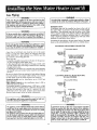
GAS PIPING WITH
_._
A gas line of sufficient size must be run to the water
heater. Consult the latest edition of National Fuel Gas
Code ANSI Z223 1, also referred to as NFPA54 and the
gas company concerning pipe size
There must be:
-A readily accessible manual shut off valve in the gas supply line serving the water heater, and
-A drip leg (sediment trap) ahead of the gas control valve
to help prevent dirt and foreign materials from entering
the gas control valve
-A flexible gas connector or a ground joint union between
the shutoff valve and control valve to permit servicing of
the unit
Be sure to check all the gas piping for leaks before lighting
the water heater Use a soapy water solution, not a match
or open flame. Rinse off soapy solution and wipe dry
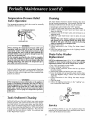
Standard Models are for installation up to 3,300 feet
above sea level.
High Altitude Models are for installation from 3,300 to
5,500 feet above sea level
If a standard model is installed above 3,300 feet or a high
altitude model is installed above 5,500 feet, the input rating must be reduced at the rate of 4 percent for each
1,000 feet above sea level. Contact your local Sears
Service Center or gas utility for further information
MANUAL
FLEXIBLE CONNECTOR
GAS SUPPLY PIPING
J_1'
SHUTOFF
li_
VALVE
_
FLEXIBLE GAS CONNECTOR
LABELED
AS COMPLYING
WITHANSI STANDARDS
LOOP
GROUND
UNION (Optional)
GAS
CONTROL
VALVE
GAS PIPING WITH ALL BLACK IRON PIPE
TO GAS CONTROL
PIPING
SHUTOFF
MANUAL
VALVE
_GAS
_[_
GROUND
UNION
WARNING
JOINTi_
SUPPLY
BLACKPIPE
/
GAS
CONTROL
VALVE
__
I The
appliance andthe
its appliance
gas connection
must be leak tested bef(_replacing
in operation.
...........
WARNING.
......
.........
The appliance and its individual shutoff valve must be disconnected from the gas supply piping systemduring any pressure
testing of that system at test pressuresin excess of'h pound
per square inch (3_5kPa).
The appliance must be isolated from the gas supplypiping system by closing its individual manual shutoff valve during any
pressure testing of the gas supply piping system at test pressures equal to or lessthan =/2pound per squareinch (3.5kPa).
WARNING
.............
-
Contaminants in the gas lines may cause improper operation
of the gas control valve that may result in fire or explosion.
Before attaching the gas line be sure that all gas pipe is clean
on the inside. To trap any dirt or foreign material in the gas
supply line, a drip [eg (sometimes caJled a sediment trap)
must be incorporate([ in the pipings"The drip. leg must, be
readily accessible, install in accordance with the Gas
Piping_' section. Refer to the latest edition of the National
Fuel Gas Code, ANSI Z223_1, also referred to as NFPA 54.
13
,'WARNING
BEFORE LIGHTING
[PROPANE (LP.) GAS WATER
HEATERS]: Propane (L.P.) gas is heavier than air.
Should there be a leak in the system, the gas will settle
near theground.
Basements, crawl spaces, skirted
areas under mobile homes (even when ventilated),
closets and areas below ground level will serve as
pockets for the accumulation
of this gas. Before
attempting to light or rellght the water heater's pilot or
turning on a nearby electrical light switch, be absolutely sure there is no accumulated gas in the area. Search
for odor of gas by sniffing at ground level in the vicinity of the appliance. If odor is €tetected, follow the steps
indicated at "For Your Safety" on the cover page of
this manual, then leave the premises.
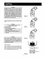
I Figure 6 I
Lighting and operating instructions are located on front of
the water heater, above or to one side of the gas control
valve
--WARNING
AN ODORANT
IS ADDED TO THE GAS USED
BY THIS WATER HEATER.
FOR YOUR SAFETY
IF YOU SMELL GAS:
1. Do not try to light any appliance.
2. Do not touch any electrical switch; do not use any
phone in your building.
3. Immediately
call your gas supplier from a neighbor's
phone. Follow the gas supplier°s instructions.
4. If you cannot reach your gas supplier, call the fire
department.
Figure 7 ]
WARNING
DO NOT force the gas control knob_ Use only your
hand to push it down to light the pilot, or to turn it to
"ON",
"OFF" or "PILOT". Never use a tool such as a
lever, wrench or pliers° Do not hit or damage the knob.
A damaged knob may result in an explosion and serious injury. If you have problem turning the knob, Call
the gas supplier immediately.
CHECK FOR LEAKS
Be sure to check, all your gas pipes for leaks before lighting your water heater.. Use a soapy water solution, not a
match or open flame. Check the factory gas fittings after
pilot is lit and gas control knob is still in "PILOT" position.
Then, check the fittings when the main burner is turned
"ON"- Use a soapy water solution for this, too.
_--_----__
_
I Figure 9 ]
15
INNER DOOR
OUTERDOOR
FOR YOUR
SAFETY
READ
BEFORE
LIGHTING
WARNING
If you do not follow these instructions exactly, a fire or explosion
may result causing property damage, personal injury or loss of life.
A. This appliancehas a pilot whichmust be lightedby
hand,Whenlightingthepilot,follow theseinstructions
exactly.
B. BEFORELIGHTINGsmellall aroundtheappliancearea
for gas. Be sure to smell next to the floor because
somegasis heavierthanair andwillsetUeon thefloor.
WHATTO DOIF YOUSMELLGAS
Donottry to lightanyappliance.
Do not touch any electric switch; do not use any
phonein yourbuilding.
, Immediatelycallyourgassupplierfrom a neighbor's
phone°Followthegassupplier'sinstructions_
LiGHTiNG
D_
iNSTRUCTIONS
1oSTOP!Readthesafetyinformation
aboveon this label.
2. Removeouterdoor.
3. Set the thermostatto lowest settinq by turning the
watertemperaturedialclockwise,(( _,)to its lowest
temperaturesetting(witharrowon dial)as shown.DO
NOT FORCE.
4oTurngas controlknobclockwlse_d'l to "OFF'*position. Knob cannotbe turned from "PILOT" to "OFF"
unlessknobis depressedslightly.DO NOT FORCE.
(Figure6,page15)
5_Waitfive (5) minutesto clearout anygas°If you then
smellgas, STOP!Follow"B" in thesafety information
aboveon this label. If you don't smellgas, go to the
next step°
6oRemove(or open) inner door locatedbelow the gas
controlunit,(Figure9, page15)
7. Find pilot-followmetaltubefrom gascontrol.The pilot
is locatedon therighthandsideoftheburner°
PILOT BURNER
C.
• If you cannotreachyour gas supplier,call the fire
department.
Useonlyyour handto pushin or turnthe gascontrol
knob. Neverusetools.If the knobwill not pushin or
turn byhand,don'ttry to repairit, calla qualified service technician.Forceor attemptedrepairmay result
in a fireor explosion.
Do not use this applianceif anypart hasbeen under
water.Immedtzitely
call a qualified servicetechnician
to inspecttheapplianceandto replaceanypartof the
controlsystemand any gas controlwhichhas been
underwater.
_THERMOCOUPLE
8. If you don't smell gas,turn knobon gascontrolcounter
c!ockwise_@ to"PILOT"position. (Figure7, page15)
9o Push in control knob all the way and hold down.
Immediatelylight thepilot with a match.Continueto
hold controlknob in for aboutone (1) minuteafter
thepilot is lit. Releaseknoband it will pop backup.
Pilotshouldremainlit. If it goes out, repeatsteps 3
through8.
• If knobdoes notpop up when released,stop and
immediatelycall your servicetechnicianor gas
supplier.
' If the pilot will not stay lit after several tries,
depressand turnthegas controlknobclockwise
@ _ to "OFF'' and callyourservicetechnician
or gassupplier.(Figure6, page15)
10.Replace(or close)inner door°Replaceouter door if
doordoes not covergas controlon/offknob or temperatureadjustmentknob.(Figure9, page15)
1!. At armslength away,turngascontrolknobcounterclockwise _
to the full "ON" position.
WARNING Do not use gas control knob to regulate gas flow. (Figure8, page15)
124At armslength away,set the thermostatto desired
setting.The mark( '_') HOTindicativeof approximate
120°Fis preferredstarting point, Some local laws
may requirea lowerstartingpoint.If hotterwateris
desired,see instruction
manualand"warning" below_
13oReplacetheouterdoor if notreplacedin step10.
WARNING
Hotterwater increases the risk of scald injury°Beforechangingtemperaturesettingsee instructionmanual
TO TURN
OFF GAS TO APPLIANCE
1oSet the thermostatto lowest settingby turningthe
watertemperaturedial clockwise(F-'_) to its lowest
temperaturesetting(witharrowon dial)as shown.DO
NOT FORCE,
_
2. Turngascontrolknobclockwise_
1 to "OFF"posi.
tion. Knobcannotbe turnedfrom "PILOT" to "OFF"
unlessknobis depressedslightly_
DO NOT FORCE.
(Figure6, page15)
3_Replaceouterdoor(if removed)_
]6
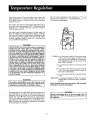
Turn the water temperature dial clockwise (('_)
to
decrease the temperature, or cour_terclockwise (#'_"_)
to increase the temperature.
Due to the nature of the typical gas water heater, the
water temperature in certain situations may vary up to
30°F higher or lower at the point of use such as, bathtubs,
showers, sink, etc,
This means that
set at the mark
temperature at
150°F or as low
when the temperature adjustment dial is
approximating 120 ° F, the actual water
any hot water tap could be as high as
as 90°E
Any water heater's intended purpose is to heat water_ Hot
water is needed for cleaning (bodies, dishes, clothing).
Hot water will present a scald hazard. Depending on the
time element, and the people involved (normal adults,
children, toddlers, elderly, infirm, etc.) scalding may
occur at different temperatures..
i i
WARNING
HOTTERWATERCAN SCALD:Water heatersare intended to
producehot water. Water heated to a temperature which
will satisfyclotheswashing, dishwashing,and other sanitizing needscan scaldand permanentlyinjureyou upon contact. Somepeopleare more likely robe permanently injured
by hot water thanothers.Theseincludethe elderly,children,
the infirm, or physically/mentallyhandicapped,if anyone
usinghot water in your homefits into one of thesegroupsor
if there is a localcode or statelaw requiringa certaintemperaturewater at the hot water tap, thenyou musttake special precautions.In additionto usingthelowest possibletemperature setting that satisfiesyour hot water needs,some
type of temperingdevice,such as a mixingvalve, shouldbe
used at the hot water taps used by these people or at the
water heater.Mixing valvesare available at plumbing supply
or hardware stores.Follow manufacturersinstruct]ons for
installation of the valves.Beforechangingthe factorysetting
on the thermostat,read the "Temperature Regulation"section in thismanual.
WARNING
V HOT-Is a thermostat setting of approximately
120°F, which will supply hot water at the
most economical temperatures.. The temperature adjustment knob can be turned lower
than "HOT" if desired.
A-Is a thermostat
130°F
setting of approximately
B-Is a thermostat setting of approximately
140°E This is the lowest setting for supply of
hot water to dishwashers°
C-Is a thermostat
150°Fo
setting of approximately
VERY HOT-Is a thermostat setting of 160°E. It is recommended that the dial be set lower whenever
possible..
!
Never allow small children to use a hot water tap, or to 1
draw their own bath water. Never leave a child or handicapped person unattended in a bathtub or shower,
m
J
NOTE: Residential gas-fired water heaters will not supply
sanitizing hot water for dishwashers.
WARNING
The thermostat of this water heater has been factory set at
its lowest position, to reduce the risk of scald injury, tt is
•adjustable and must be reset to the desired temperature
setting. The mark (Y) HOT indicative of approximately
120°F is the preferred starting point. Some states have a
requirement for a lower setting. If you need hotter water,
follow directions for temperature adjustment, but beware
_f the warnings in this section.
Should overheatin_ occur or the gas supply fail to
shut o_'f,turn "OFF' the manual gas control valve to
the appliance.
17
Start Up Conditions
CONDENSATION
Whenever the water heater is filled with cold water, a certain amount of condensation will form while the burner is
on. A water heater may appear to be leaking when in fact
the water is condensation. This usually happens when:
a. When a new water heater is filled with cold water for
the first time.
b When gas burns and water vapor is produced in
water heaters, particularly high efficiency models
where flue temperatures are lower.
c When you use large amounts of hot water in a short
time and the refill water is very cold.
The water within the water heater tank expands as it is
heated and increases the pressure of the water system If
the relieving point of the water heater's temperature-pressure relief valve is reached, the valve will relieve the
excess pressure ]'he temperature-pressure relief valve is
not intended for the constant relief of thermal expansion°
This is an unacceptable condition and must be corrected.
Moisture from the products of combustion condense on
the cooler tank surfaces and form drops of water which
may fal[ onto the burner or other hot surfaces to produce
a "sizzling" or "frying" noise
It is recommended that any devices installed which could
create a closed system have a by-pass and/or the system
have an expansion tank to relieve the pressure built by
thermal expansion in the water system. Expansion tanks
are available for ordering through the Sears Service Center.
Contact the local plumbing inspector, water supplier
and/or the Sears Service Center for assistance in controlling these situations
Excessive condensation can cause pilot outage due to
water running down the flue tube onto the main burner
and putting out the pilot.
STRANGE
Because of the suddenness and amount of water, condensation water may be diagnosed as a "tank leak". After the
water in the tank. warms up (about I-2 hours), the condition should disappear_
SOUNDS
Do not assume the water heater is leaking until there has
been enough time for the water in the tank to warm up.
Possible noises due to expansion and contraction of some
metal parts during periods of heat-up and cool-down do
not represent ha rmfu I or dangerous conditions
Condensation causes sizzling and popping with the burner area during heating and cooling periods and should be
considered normal See "Condensation" section
An undersized water heater will cause more condensation. The water heater must be sized properly to meet the
family's demands for hot water including dishwashers,
washing machines and shower heads
Operational
Excessive condensation may be noticed during the winter
and early spring monti_s when incoming water temperatures are at their lowesL
SMELLY WATER
In each water heater there is installed at ]east one anode
rod (see parts section) for corrosion protection of the tank,
Certain water conditions
will cause a reaction between
this rod and the water The most common complaint associated with the anode rod is one of a "rotten egg smell".
This odor is derived from hydrogen sulfide gas dissolved
in the water, The smell is the result of four factors which
must all be present for the odor to develop:
Good venting is essential for a gas fired water heater to
operate properly as well as to carry away products of
combustion and water vapor
SMOKE/ODOR
It is not uncommon to experience a small amount of
smoke and odor during the initial start-up. This is due to
burning off of oil from metal parts, and will disappear in a
short whiles
THERMAL
Conditions
a a concentration
of sulfate in the supply water_.
b little or no dissolved oxygen in the water
c_ a sulfate reducing bacteria within the water heater,
(This harmless bacteria is non-toxic to humans.)
d an excess of active hydrogen
in the tank This is
caused by the corrosion
protective
action of the
anode
EXPANSION
Water supply systems may, because of high line pressure,
frequent cut-offs, the effects of water hammer and others,
..... ha_,,ei_stalied de_i_es such as p're_u?e i-ecrdcihg"valves,
check valves, back flow preventers, etc_.to control these
types of problems. When these devices are not equipped
with an internal by-pass, and no other measures are
taken, the devices cause the water system to be closed, As
water is heated, it expands (thermal expansion) and
closed systems do not allow for the expansion of heated
water.
Smelly water may be eliminated-or
reduced
in-some .....
water heater models by replacing the anode(s) with one of
less active material,
and then chlorinating
the water
heater tank and all hot water lines, Contact the local Sears
Service Center for further information
concerning
an
Anode Replacement Kit #9001453 and this Chlorinatic_
Treatment,
18
NOT
If the"smelly water persists after the anode replacement
and chlorination treatment, we can only suggest that continuous chlorination and filtering conditioning equipment
be considered to eliminate the water problem
t
WATER
3_
FAUCETS
_IYDROGEN GAS: Hydrogen gas can be produced in a
ot water systemthat has not been used for along period of time (generallytwo weeks or more). HydroEen _as
is extremely flammable and explosive. To prevent t-he
possibility of injury under these_conditions, we recommend the hot water faucet be opened for several minutes at the kitchen sink before any electrical appliances
which are connected to the hot water system are used
(such as a dishwasheror washing machine). If hydrogen
gas is present, there will probably be an unusual sound
similar to air escapingthrough the pipe as the hot water
faucet is opened. T|iere must be no smoking or open
flame near the faucet at the time it is open.
TEMPERATURE
SHUT
If the pilot is not lit, follow the "Lighting" instructions
in this manual or located above the gas control valve
on the water heater to relight the pilot. If the water
was extremely hot and is now cold, the high limit safety temperature shut off may have put out the burner
and pilot. If the high temperature shut off activates, the
gas control valve must be replaced. Contact the Sears
Service Center
knob must be turned to the "ON"
5_ The temperature adjustment dial may be set too low
See the "Temperature Regulation" section.
6. The gas company can check the gas input to see if it is
correct, An underfired water heater will not heat water
as quickly
7 Look for leaking or open hot water faucets. Make sure
all are closed..
8 The cold water inlet temperature may be colder during
the winter months_ It will take longer to heat the water
and seem like less hot water.
9 If you cannot find what is wrong, call the Sears Service
Center.
OFF SYSTEM
WATER
This water heater is equipped with an automatic gas shut
off system. The high temperature shut off is built into the
gas control valve. This system shuts off the gas supply to
the water heater burners when high water temperatures
are present. It is non-resettable, If the high temperature
shut off activates, the gas control valve must be replaced,
If this were to occur, turn "OFF" the entire gas supply to
the water heater Contact the Sears Service Center.
WARNING
WATER
Check the manual gas shut off valve to be sure it is
open.
4, The gas control
position.
WARNING
HIGH
OR NO HOT
2. Check the pilot flame. It may have gone out. All models have an opening behind the outer door for viewing
the pilot
Do not remove the anode leaving the tank unprotected.
By doing so, all warranty on the water heater tank is
voided.
"AIR" IN HOT
ENOUGH
IS TOO
HOT
1. The temperature adjustment dial may be set too high,
See the "Temperature Adjustment"
section.
NOTE: A period of time is necessary after an adjustment has been made for the water temperature
to
reach the new temperature setting.
2 tf lower temperature settings will not lower the water
temperature, caJl the Sears Service Center.
1
shut off, turn "OFF_' the manual gas control valve tO | .......
Should overheating occur or the gas supply fail to
the appliance.
.......
[
t9
Venting System Inspection
At least once a year a visual inspection should be made of
the venting system. You should look for:
I Obstructions which could cause improper venting,, The
combustion and ventilation air flow must not be
obstructed.
2. Damage or deterioration which could cause improper
venting or leakage of combustion products,
3, Rusted flakes ar_oundtop of water heater,
WARNING
sure the ventpiping
is properly connected to pret escape of dangerous
flue gasses which could
_a_,n
--WARNING
se deadly asphyxiation°
Soot build-up indicates a problem that requires correction before further use. Turn "OFF" gas to water
heater and leave "OFF" until repairs
are made,
because failure to correct the cause of the sooting can
result in a fire causing DEATH, SERIOUS BODILY
INJURY, OR PROPERTY DAMAGE.
]
WARNING
Obstructions
and deteriorated vent systems may pre- I
sent serious health risk or asphyxiation.
I
Burner Cleaning
WARNING
In the event your burner needs cleaning, use the following
instructions:
Chemical vapor corrosion of the flue and vent system
nay occur ifalr for combustion contains certain chemca/vaporso Spray can propellants, cleaning solvents,
•efrigerator and air conditioner refrigerants, swimmin_
)ool chemicals, calcium and sodiun_ chloride, waxes_
)leach and process chemicals are typical compounds
which are potentially corrosive.
,
If inspection of the burner shows that cleaning is required,,
turn the gas control knob clockwise (/"_)
to the "OFF'
position, depressing slightly.,
NOTE: The knob cannot be turned from "PILOT" to
"OFF" unlessknob is depressedslightly. DO NOT FORCE°
Loose deposiLs on or around the burner can be removed
by carefully using the hose of a vacuum cleaner inserted
through the access door of the water heater_ If the burner
needs to be removed for additional cleaning, call the Sears
Service Center to remove and clean the burner and correct
the problem that required the burner to be cleaned,
WARNING
If after inspection
or deterioration,
Technician must
[ and the flue and
of the vent system you found sooting
something is wrong; a Sears Service
be called in, the problem corrected,
venting cleaned or replaced before
resuming operation on the water heater.
Housekeeping
Vacuum around base of water
lint on a regular basis,
Burner Inspection
F
heater
for dust, dirt,
and
WARNING
|Do not use this appliance if any part of it has been
[under
water.
Immediately
calla
Sears Service
_Techniclan
to inspect the appliance and to replace the
tgas control or any part of the burner system which has
WARNING
INSTALLED
IN SUITABLE
AREA: To insure sufficient
ventilation and combustion air supply, proper clearances from the water heater must be mamtalned. See
"Locating
the
New
Wiiter
Heater"
section.
Combustible materials such as clothing, cleaning materials, or flammable
liquids, etc_ must not be placed
against or adjacent to the water heater which can
cause a fire.
been under water.
At least once a year a visual inspection should be made of
the main burner and pilot burner, The drawing is for your
reference,
You should check for sooting which is not normal and
will impair proper combustiom
20
Temperature-Pressure
Relief
Draining
Valve Operation
The water heater should be drained if being shut down
during freezing temperatures° Also periodic draining and
cleaning of sediment from the tank may be necessary.
The temperature-pressure relief valve must be manually
operated at least once a year.
' Turn thethe
gascpntro]
knob
the "OFF"
..CLOSE
cold water
inlettovalve
to the position°
water heater,
3. OPEN a nearby hot water faucet and leave open to
allow for draining.
4. Connect a hose to the drain valve and terminate to an
adequate drain.
5r OPEN the water heater drain valve to allow for tank
draining..
NOTE: if the water heater is going to be shut down
and drained for an extended period, the drain valve
should be left open with hose connected allowing
water to terminate to an adequate drain.
6.. Close the drain valve._
7. Follow instructions in the "Filling The Water Heater"
section,
8 Follow the lighting instructions in the "Lighting" section
to restart the water heater.
TEMPERATURE_PRESSURE
DISCHARGE PIPE
WARNING
When checking the temperature-pressure relief valve
operation, make sure that (1) no one is in front of or
around the outlet of the temperature-pressure relief
valve discharge line, and (2) that the water manually discharged wilt not causeany property damage becausethe
water may be extremely hot.
If after manually operating the valve, it fails to completely reset and continues to release water, immediately
close the cold water inlet to the water heater, follow the
draining instructions, and replace the temperature-pres_
sure relief valve with a new one_
Drain Valve Washer
Replacement
NOTE: For replacement, use a _%2"x '¾4_=x %"thick washer
available at your nearest hardware store. For ordering
replacement washers,refer to the "Repair Parts" section.
1. Turn "OFF" gas supply to water heater.
2 Follow "Draining" instructions.
3 Turning counter clockwise, remove the hex cap below
the screw handle.
4 Remove the washer and put the new one in place.
5. Screw the handle and cap assembly back into the drain
valve and retighten using a wrench DO NOT OVER
TIGHTEN.
6 Follow instructions in the "Filling The Water Heater"
section.
7. Check for leaks
8. Follow the lighting instructions in the "Lighting" section to restart the water heater..
Failure to install and maintain a new properly listed temperature-pressure relief valve will release the manufacturer from any claim which might result from excessive temperature or pressure
WARNING
If the temperature-pressure relief valve on the appliance
weeps or discharges periodically, this may be due to
thermal expansion. Your water heater may have a check
valve installed in the water line or a water meter with a
check valve. Consult the SearsService Center for further
information. Do not plug the temperature-pressure
relief valve_
WASHER
Tank (Sediment) €leaning
..........
......
Sediment build-up on the tank bottom may create varying
amounts of noise, and if left in the tank will cause premature tank failure In some water areas, you may not be
able to drain all sediment deposits by simply draining the
tank In these cases Mag Erad(part no 3515) can be used
to help remove the sediment deposits, This may be
ordered from the Sears Service Center For ordering, refer
to the "Repair Parts" section
Service
if a condition
persists or you are uncertain
about the
operation of the water heater, let a qualified person check
it ouL Call the Sears Service Center
21
CAUTION
Read this manual first. Then before checking the water
heater make sure the gas supply has been turned "OFF",
and never turn the gas "ON" before the tank is completely full of water.
If youarenotthoroughlyfamiliarwith gascodesyour
waterheater,andsafetypractices,contactthe Sears
Service
Centertocheckthewaterheater°
CAUTION
Never use this water heater unless it
with water. To prevent damage to the
be filled with water. Water must flow
faucet before turning "ON" gas to the
O
O
®
O
is completely filled
tank, the tan]_ must
from the hot water
water healer.
Water at the draft hood is water vapor which has
condensed out of the combustion products° This is
caused by a problem in the vent, Contact the Sears
Service Center°
*Condensation
may be seen on pipes in humid
weather or pipe connections
may be leaking,
*The primary anode rod fitting may be leaking.
Small amounts of water from temperature-pressure
relief v:alve may be due to thermal expansion or high
water pressure in your area_
temperature-pressure
@ *The
ing at the tank fitting
relief valve may be leak-
from a drain valve may be due to the valve
@ Water
opened slightly
O
O
*The drain valve may be leaking at the tank fitting
Combustion products contain water vapor which can
condense on the cooler surfaces of the tank_ Droplets
form and drip into the fire or run on the floor. This is
common at the time of startup after installation and
when incoming water is cold.
in the water heater bottom or on the floor may
@ Water
be from condensation, loose connections, or the
relief valve. DO NOT replace the water heater until
a full inspection of all possible water sources is made
and necessary corrective steps taken
Leakage from other appliances, water lines, or
groundseepage should also be chec_ked
*To check where threaded portion enters tank, insert Q-Tip between jacket opening and fitting If cotton is wet, follow
"Draining" instructions in the "Periodic Maintenance" section and then remove fitting, Put pipe dope or teflon tape on the
threads and replace_ Then follow 'F'll'ng the Water Heater" instructions in the "Instalhng the New Water Heater" sect'on.
22
23
ECONOMIZER TM 5 GAS WATER HEATERS
MODEL NUMBERS:
153.333000
153.333030
153.333031
153_333100
153.333130
30
30
30
40
40
Gal_ High Altitude
Gal.
Gal.
Gah High Altitude
Gal.
i----
I V
17 i
24
I8
.....
ECONOMIZER TM 5 GAS WATER HEATERS
MODEL NUMBERS:
153o333000
153.333030
153.333031
153.333100
153_333t30
30
30
30
40
40
Gal. High Altilude
Gal.
Gal.
Gal. High Altitude
Gal.
MOD,ELNUMBERS
153.333000 153.333030 t53.333031 153.333100 153.333130
KEY
PART NUMBERS
9000071
9000071
9000071
9000279
9000279
9000279
9000279
2____ Primary Anode Rod
i
9000279
0270118
0270118
0270118
0270118
0270118
3
Model Rating Plate -I9000254
9000254
9000254
9000254
9000254
4
Drain Valve
9001584
9001584
9001584
9001584
5
Drain Valve Washer ('%_"x Wd' x '/." thick)** 9001584
'F145-o08g
i45-oo85 F145-0085 Ft45-0085 F145-0085
6 , Thermocoup!e Clip
F145-0609 9000284
9000284
9000284
9000284
7
Pilot
42-9231
42-9231
42-9231
42-9231
42-9231
........
8
Th'ermocouple*
......
9000278
9000278
9000278
9000278
9000278
9
Pilot Tubing w/Fittings
0230182
0230122
0230129
0230181
0230182
I0
Burner Orifice
(#43)HA
(#40)
Drill Size
(#40)
(#41)HA _ (#38)
9000739
9000739
9001626
9001626
9000739
11
Manifold
i i
9000349
9000349
9000703
9000349
9000349
12
Burner
[
9000351
9000351
9000351
9000351
9000351
13
Outer Door
9000281
9000281
9000281
9000281
9000281
14
Inner Door
F145-0842
- ! 5.........
Gas Control Valve
F145-0842 Ft45-0842 LF145-0842 F145-0842
F145-0697 !F145-0697 F145-0697 Ft45-0697i Ft45-0697
16
Temperature Adiustment Knob
9001852
9001852
9001852
9001852
9001852
17
Dip Tube
9000360
9000360
9000360
9000360
9000360
t8
Flue Baffle
9000272
9000272
9000272
9000272
9000272
t9
Draft Hood
3515
#
Mag-Erad
0291348
#
Manual
NO.
1
PARTDEscrIPTION
Temperature-Pressure Relief Valve
..........
.....
9000071
9000071
......
If the parts you need are not stocked locally, your order
will be electronically transmitted to a Sears Repair Parts
Distribution-Center for handling_,
* These parts are also available at most Searsretail stores.
** Also available at most hardware stores
tReplaced only on return of damaged plate
# Not Illustrated
The model number of your Gas Water Heater will be
found on the model rating plate located above the gas
control valve
Now that you have purchased your Gas Water Heater,
should a need ever exist for repair paris or service, simply
contact any SearsService Center, Be sure to provide all pertinent facts when you call or visit.
WHEN ORDERING REPAIR PARTS, ALWAYS GIVE THE
FOLLOWING INFORMATION:
MODEL NUMBER
NAME OF ITEM
PART NUMBER
PART DESCRIPTION
All parts listed may be ordered from any Sears Service
Center and Most Searsstores
THIS IS A REPAIR PARTS LIST, NOT A PACKING
25
LIST.
ECONOMIZER _ 5 GAS WATER HEATERS
MODEL NUMBERS:
153.333131
!53_333530
153.333531
40 Gal.
50 Ga|_
50 Gal.
19(
17
18
15
\
\
14
26
ECONOMIZER _ 5 GAS WATER HEATERS
MODEL NUMBERS:
153o333131
153.333530
153.333531
40 GaL
50 Gal.
50 GaL
........... MODEL NUMBERS
153.333t31 _153.333S30 153.333531
PA ESCRI
T
,ON
....
PART NUMBERS
9000071
9000071
9000071
.......
1
2
Temperature-Pressure Relief Valve
Primary Anode Rod
3
4
-'_
Model Rating Plate 4................
Drain Va[ve
D'iain Valve Washer'i'%2"x '¥_" x'"%"thiciii'**
---6-7
Thermocouple Clip
Pilot
F145-0085
F145-0085........
F145-0609 9000284
8
--9,
I0
Thermocouple*
P'flotTubing"w/E!tting's
Burner Orifice
42-9231
'"9'000278
0230129
........
ii
--_
Drill Size
Manifold
Burner
9000279 .......
000279 9000279
_
0270118
9000254
9000254
9001584
F145-0085
F145-0609
42-9231
9000278
0230129
9000351
9000281
15 I Gas Control Valve
16 j Temperature Adjustment Knob
17
Dip Tube
18
Flue Baffle
Draft Hood
Mag-Er'a'd
Manual
0270118
(#38)
9001626
9000703
.............
I_.__3 Outer Door
14
Inner Door
9
0270118
9000254
9001584
F145-0842
F145-0697
9001852
9000360
......
[ 9000272
These parts are also available at most Searsretail stores
** Also available at most hardware stores
tReplaced only on return of damaged plate
# Not ]llustrated
9001584
42-9231
9000278
0230129
(#38)
(#38)
9001665
9001665
9000349
9000703
90OO351 9000351
9000281
9000281
F145-0842 F145-0842
F145-0697 F145-0697
9001852
9001852
9000360
9000360
9000272
9000272
3515
0291348
If the parts you need are not stocked locally, your order
will be electronically transmitted to a Sears Repair Parts
Distribution Center for handting.
The model number-of your Gas Water Heater will be
found on the model rating plate located above the gas
control valve
Now that you have purchased your Gas Water Heater,
should a need ever exist for repair parts or service, simply
contact any SearsService Center Be sure to provide all pertinent facts when you call or visit
WHEN ORDERING REPAIR PARTS, ALWAYS GIVE THE
FOLLOWING INFORMATION:
MODEL NUMBER
NAME OF ITEM
PART NUMBER
PART DESCRIPTION
All parts listed may be ordered from any Sears Service
Center and Most Searsstores
THIS IS A REPAIR PARTS LIST, NOT A PACKING
27
LIST.
ON INSTALLATIONS NOT MADE BY SEARS AUTHORIZED CONTRACTORS:
1. Your Sears warranty applies to the product only
2 Sears does not warrant the installation.
3 A charge will be made on service calls due to poor or
incomplete installation These include:
a..Adjusting thermostat
b Lighting pilot.
c. Leaks in pipes or fittings
About Your Warranty
Some warranties say that you must drain the tank once a
month. Your tank will last longer if you do this Your Sears
warranty is good whether you drain the tank often or not
We include a drain valve because:
I, Many plumbing codes require a drain valve.
2.. Your water heater will continue to heat efficiently, if a
small amount of water is drained each month
THE
PRICE OF YOUR
WATER
HEATER
DOES NOT
INCLUDE
A FREE CHECKUP
SERVICE CALL. ON
WATER HEATER INSTALLATIONS
ARRANGED
BY
SEARS, Sears warrants the installation
This manual is in non-technical language It may help
you avoid the cost of a needless service call Many service calls really aren't needed Such as when:
1. The gas is turned "OFF"
2 The pilot is out.
3 A gas or water leak is due to loose pipe or connections
FULL ONE YEAR WARRANTY ON WATER HEATER
For one year from the date of purchase, when your Sears Kenmore water heater is installed and operated in
accordance with the instructions in this manual Searswill:
l Repair defects in material or workmanship in this water heater, free of charge
2 Furnish and install a new current model water heater of equal capacity and quality, free of charge, if a leak
occurs in the tank
LIMITED WARRANTY ON TANKS THAT LEAK
After one year and through 5 years from the date of purchase, if a leak occurs in the tank, Sears will furnish a
new current model water heater of equal capacity and quality You will be charged for installation
If the water heater is subiected to commercial, institutional, industrial or other non-residential use, the above
warranty coverage for tanks that leak is effective for 2 years from the date of purchase.
To obtain warranty service, SIMPLY CONTACT THE NEAREST SEARSSTORE OR SEARSSERVICECENTER IN
THE UNITED STATES "This warranty applies only while this product is in use in the United States"
This warranty gives you specific legal rights and you may also have other rights which vary from state to state
"SEARS,ROEBUCK AND CO,, Dept 817 WA, Hoffman Estates,IL 60179"
Sears Installation
Policy
Sears Installation
Warranty
In addition to any warranty extended to you on the Sears
merchandise involved, which warranty becomes effective
the date the merchandise is installed should the workmanship of any Sears arranged installation prove fau]ty within
one year, Sears will, upon notice from you, cause such
faults to be corrected at no additional cost to you.
All installation labor arranged by Searsshall be performed
in a neat, workmanlike manner in accordance with generally accepted trade practices. Further, all installations shall
comply with all _local laws, codes regulations and ordinances. The customer sha[l also be protected, during
installation, by insurance relating to property damage,
Worker's Compensation and Public Liability
If you want this water heater professionally installed by Sears, contact your Sears Salesperson He will arrange for prompt,
quality installation by Searsauthorized contractors
(8-94)
0291348-00
28
Sears, Roebuck and Co., Hoffman Estates,IL 60179 U.S.A.