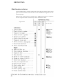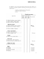
1
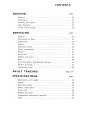
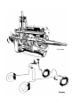
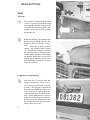
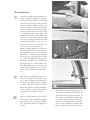
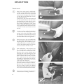
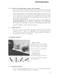
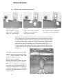
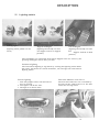
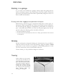
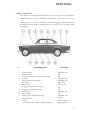
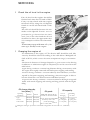
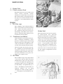
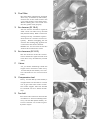
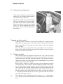
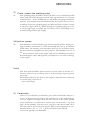
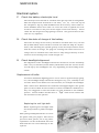
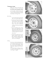
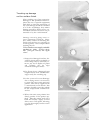
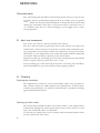
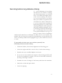
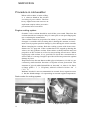
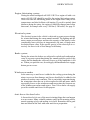
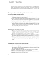
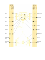
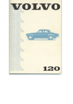
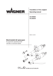
TWO- AND FOUR-DOOR
CARS
( 121/122
S
M)
DESCRIPTION DRIVING
SERVICING
BEFORE YOU START DRIVING YOUR NEW VOLVO
PLEASE READ THROUGH THIS
INSTRUCTION BOOK CAREFULLY. IT CONTAINS ALL
THE INFORMATION YOU NEED TO BE ABLE TO
DRIVE AND SERVICE YOUR VEHICLE IN THE BEST
POSSIBLE WAY. BY FOLLOWING THE INSTRUCTIONS
GIVEN IN THIS BOOK, YOU WILL FIND THAT
YOUR VOLVO WILL COME UP TO ALL THE
EXPECTATIONS CONCERNING ECONOMICAL
OPERATION AND EXCELLENT PERFORMANCE THAT
YOU HAVE EVERY RIGHT TO EXPECT OF
A TOP-QUALITY VEHICLE.
THIS INSTRUCTION BOOK IS NOT INTENDED TO
BE A COMPREHENSIVE TECHNICAL MANUAL AND
DOES NOT CLAIM TO MAKE THE
READER INTO A PERFECT CAR MECHANIC. IT WILL,
HOWEVER, SHOW YOU HOW TO LOOK AFTER YOUR
VEHICLE SO THAT TROUBLE IN THE FUTURE
CAN BE AVOIDED
AB VOLVO
DO NOT
WAIT UNTIL SOMETHING GOES
WRONG BEFORE YOU START READING
THIS BOOK. READ IT NOW.
THE SHORT TIME THIS TAKES WILL MORE THAN
REPAY YOU IN THE LONG RUN.
THE BETTER YOU KNOW YOUR VOLVO, THE
BETTER SERVICE IT CAN GIVE YOU.
THIS BOOK CAN CONTAIN SOME VALUABLE
INFORMATION EVEN FOR AN EXPERIENCED
MOTORIST
FINALLY, WE WOULD LIKE TO EXPRESS OUR
APPRECIATION FOR THE CONFIDENCE
YOU HAVE SHOWN IN THE NAME OF VOLVO
BY CHOOSING A VOLVO VEHICLE.
WE ARE SURE THAT THE DEMANDS YOU MAKE
ON YOUR VOLVO WILL BE MORE THAN
SATISFIED, APART FROM THE FACT THAT YOU
WILL ENJOY DRIVING IT, AND THAT IT WILL
GIVE YOU FAITHFUL SERVICE FOR MANY,
MANY MILES.
3
CONTENTS
4
CONTENTS
VOLVO SERVICE
Volvo Service Organization
In order to get the most out of the invested capital represented by a car,
it must be looked after and serviced rationally. Volvo has gone to a great
amount of trouble in the design and selection of material to ensure that
the car in question only requires a minimum of servicing. All this work
will be in vain unless we can count on your co-operation - that is to
say, that you make sure that your vehicle gets the regular 'servicing it
needs. In order to help you, Volvo has built up a world-wide service
organization. All Volvo dealers have specially trained personnel and
receive a continuous supply of technical information from the Volvo
Service Organization concerning repair and adjustment work. They have
also special tools, designed at the Volvo factory.
All Volvo dealers have a comprehensive stock of spare parts which is
your guarantee for genuine Volvo spares. This is why our dealers are in
the very best position to give your vehicle first-class service concerning
both maintenance operations and repairs. You should also refer to your
dealer if you need information about your Volvo that is not included
in this instruction book.
It is not only in your own country that there is a Volvo workshop within
easy reach but Volvo also has a widely distributed service network in
other countries too.
6
VOLVO SERVICE
Warranty and Service Booklet
A warranty and service booklet accompanies each vehicle when it is
delivered. This book contains a coupon entitling you to a cost-free service inspection after 2 500 km (1 500 miles) running. If possible, let the
dealer who supplied the vehicle carry out this service inspection. If necessary, however, any of our dealers can do this.
I f our six-month guarantee is to apply, we make one absolute condition
and that is that the above-mentioned cost-free inspection is carried out
at roughly the mileage shown and that the vehicle has been looked after
in accordance with the instructions in this book.
Service Inspections
After the cost-free service inspection has been carried out, you should
make an agreement with your dealer concerning continued, regular service inspections in accordance with the suggestions made in our Service
Book. Thorough and regular servicing is o f vital importance for the performance and length o f life o f the vehicle.
Always use genuine Volvo spares.
7
DESCRIPTION
General
The Volvo 121/122 S is a two- or four-door, five-seater car. Many
colours are available and in each particular case the colour of the internal
fittings and upholstery harmonizes with the external finish of the car.
In addition to a spacious luggage compartment, where the spare wheel
and tool kit are stowed, there is also plenty of storage space inside the
car itself, such as a shelf with its own lighting under the dashboard,
a recessed hat shelf below the rear window and roomy pockets on the
inside of the front doors. Standard equipment on the car includes a trip
meter in the speedometer, a windscreen washer and a back-up light which
goes on automatically when the reverse gear is engaged. Both front seats
are fitted with safety belts. The car is of the integral construction type
so that there is no separate frame. The front and rear suspensions as
well as the engine and transmission are attached directly to the body.
The surface finish of the body is synthetic and the primer used rustproofs the body. The car is also thief-proof since the connection between
the ignition switch and the ignition coil is in the form of an armoured
cable.
8
Type designations
This instruction book deals with vehicles having the
following type designations:
Type designation
121341
121361
122341
122351
122461
131211
131341
131361
132341
132461
M
M
M
M
M
M
M
M
M
M
or
or
or
or
or
or
or
or
or
or
121342
121362
122342
122352
122462
131212
131342
131362
132342
132462
M
M
M
M
M
M
M
M
M
M
Engine
B 18 A
B 18 A
B 18 D
B 18 D
B 18 D
B 18 A
B 18 A
B 18 A
B 18 D
B 18 D
Gearbox
M 40
BW 35*
M 40
M 41
BW 35*
M 30
M 40
BW 35*
M 40
BW 35*
On the USA market, 12234 and 13234 have designations 12244 and 13244 respectively.
Moreover, the letter
M is not included in the
type designation for the models on the USA market.
1. The type designation and chassis number are
stamped on the cowl under the bonnet.
2. Stamped on a plate to the left under the bonnet
is the type designation together with the code numbers for colour and upholstery.
3. The engine type designation, part number and
serial number are given on the left-hand side of
the cylinder block. The last figures of the part
number are stamped on a tab. The serial number
follows this with all the figures stamped on. For
i dentifying the engine, both the part number and
serial
number should be quoted, for example
496801-12345.
:j.) See separate supplement.
In all correspondence con-
cerning your vehicle with
the dealer and when orderi ng spare parts, the type
designation, chassis and en-
gine number should always
be quoted.
DESCRIPTION
The engine is a four-cylinder carburettor unit with overhead valves.
The pistons are made of light-alloy and the upper compression ring on
each piston is chromed. The main bearings and connecting rod bearings
are replaceable. The crankshaft is statically and dynamically balanced.
Engine type B 18 A has an output of 85 h.p. (SAE) and is equipped with
Zenith-Stromberg horizontal carburettor.
Engine type B 18 D has an output of 100 h.p. ( SAE ) and is equipped
with twin SU horizontal carburettors.
Fuel system
The fuel system is fed from the tank to the carburettor by a fuel pump
which is driven by a cam on the engine camshaft. There is a filter in the
fuel pump which traps water and other impurities in the fuel.
Lubricating system
The engine lubrication is taken care of by a gear pump which sucks up
oil from the sump on the bottom of the engine and forces it through the
oil filter out to the lubricating points in the engine. A relief valve is
built into the oil filter which prevents the oil pressure from reaching
excessively high values.
Cooling system
The engine is water-cooled and the cooling system is of the pressure type.
Water is circulated by means of a pump fitted on the fan shaft. A thermo°
stat with an opening temperature of about 76 ° C (169 F) prevents the
cooling water from passing through the radiator before the engine has
reached its normal working temperature.
10
1. Carburettor (B 18 D)
2. Float chamber (B 18 D)
3. Air cleaner (B 18 D)
4. Expansion tank with
filler cap for coolant
5. Charging control
6. Dynamo
7. Oil filler cap
8. Air cleaner (B 18 A)
9. Carburettor (B 18 A)
10. Battery
11. Hoses for heater system
12. Oil dipstick
13. Distributor
14.
15.
16.
17.
19.
18.
20.
21. Relay for back-up light
22. Relay for headlight
Heater
flasher
Starter motor
23. Motor for windscreen
Ignition coil
washers
Plate with type desig- 24. Fluid container for
nation and code for
windscreen washers
colour and upholstery 25. Oil trap
Fusebox
26. Fuel pump
Brake fluid container 27. Steering box
Clutch fluid container 28. Horn
11
DESCRIPTION
Electrical system
The electrical system is of the 12-volt type and is fitted with a voltage control dynamo. The starter motor is controlled from the instrument
panel by means of the ignition key. This key also forms the main switch
for the rest of the electrical system. The cables to the headlights, parking
lights and internal lighting, however, are not taken over the ignition
switch but can be switched on and off without the ignition key being in
position.
Lighting
The lighting on the vehicle consists of two headlights (full and dipped)
together with two combined flasher and parking lights. At the rear the
lighting consists of two tail lights including flashers, combined lamps for
the tail lights and brake warning lights, and the back-up light. Internal
lighting consists of a roof light above the rear view mirror and a light
for the parcel shelf.
See pages 42-44 concerning replacement of bulbs.
Fuses
12
The electrical system is protected by means of fuses fitted in a fusebox to
the left on the bulkhead under the bonnet. When replacing a fuse, be sure
that you use a one of the right rating. If one of the fuses should blow
repeatedly, do not fit a more powerful fuse. Instead, take the vehicle to
a workshop for a check of the electrical system.
1. Flasher and parking
light, left
2. Headlight, left
3. Horn
4. Headlight, right
5. Flasher and parking
light, right
6. Connector
7. Junction block
8. Relay for headlight
signal
9. Reversing light
contact
10. Distributor
11. Dynamo
12. Charging control
13. Relay for reversing
light
14. Relay for overdrive')
15. Overdrive contact')
16. Ignition coil
17. Oil pressure
warning indicator
18. Foot dipper switch
19. Solenoid for
overdrive')
20. Starter motor
21. Windscreen washer
1
)
22. Battery
23. Fusebox
24. Brake contact
25. Door contact, left
26. Light signal device
27. Relay for horn
28. Overdrive switch')
29. Roof light
30. Switch for roof
light
31. Flasher unit, direction indicators
32. Door contact, right
33. Control lamp for
charging
34. Control lamp for
fullbeam headlights
35. Control lamp for
direction indicators
36. Control lamp for
oil pressure
37. Fuel gauge
38. Windscreen wiper
39. Instrument lighting
40. Ventilation fan
41. Control lamp for
overdrive
42. Control for wind-
Applies only to cars equipped with overdrive
screen wiper and
washer
43. Lighting switch
44. Ignition switch
45. Cigarette lighter
46. Control for
ventilation fan
47. Glove compartment
lighting
48. Switch for glove
compartment
lighting
49. Fuel gauge
impulse unit
50. Rear lamp, left, with
rear light, stop light,
flasher and back-up
light
51. Number plate
lighting
52. Rear lamp, right,
with rear light,
stop light, flasher
and back-up light
A = White E = Grey
B=Black F =Yellow
C= Blue
G=Brown
D = Green H =Red
I = Spare lead
DESCRIPTION
Power transmission
Clutch
The function of the clutch is to transmit the power from the engine to
the gearbox. The clutch is of the single dry plate type with diaphragm
spring. The diaphragm spring 'functions partly as a lever when declutching and partly as a pressure spring when engaging.
Gearbox
The gearbox is used to regulate the speed ratio between the engine and the
rear axle so that the engine always operates in its most favourable speed
range. The gearbox is synchronised on all the forward gears; this means
that gear-changing can be carried out without double declutching. Since
the gearbox is fitted with helical gears and the gear lever is rubber insulated, excellent sound insulation is obtained. See page 57 for data.
Propeller shaft
The propeller shaft, which is the connecting link between the gearbox
and the rear axle, is divided into two sections. The forward section is
journalled at its rear end in a bearing housing suspended in a rubberized
ring.
Rear axle
The driving power of the engine is transmitted from the propeller shaft
to the rear wheels through the rear axle. The rear axle is of the hypoid
type, i.e. drive pinion is below the centre line of the drive shafts. See
page 57 for data.
Brakes
The vehicle is equipped with disc brakes at the front and drum brakes
at the rear as standard. The brake system is also provided with a reducer valve, which prevents involuntary locking of the rear wheels.
The footbrake system is hydraulic and influences all four wheels. The
hydraulic system consists of a 'fluid-filled master cylinder which, when
the brake pedal is depressed, transmits the brake pressure through the
brake fluid in the lines to the wheel unit cylinders. The plungers in these
are then pressed outwards and apply the brake shoes or brake pads respectivly.
Vehicles fitted with the B 18 D engine are also provided with vacuum
type servo brake cylinders.
The handbrake system operates mechanically on the rear wheels.
Wheels and tyres
14
The vehicle has pressed steel wheels with lugs for the attachment of the
hub caps. All wheels are carefully balanced and the tyres are of the tubeless type.
Gearbox
15
DESCRIPTION
Body
Bonnet
The bonnet is fitted with a catch
which is operated from the driving
seat through a handle located to the
left under the instrument panel. The
bonnet catch is released by pulling
the handle out.
When the bonnet catch handle has
been released inside the car, the
bonnet is still retained by a safety
catch. After this is pressed in as
shown, the bonnet can be lifted
up. When the bonnet is closed
the bonnet catch is automatically
locked and cannot be lifted until
the handle inside the car has been
pulled again. Check to make sure
that the bonnet is properly secured
when it is closed.
Luggage compartment
The door key is used to lock the
luggage compartment, which is opened by pressing the handle upwards
as shown. The luggage compartment
lid is balanced and does not need
to be held up. To the left in the
compartment there is room for the
spare wheel and tool kit. Always
make sure that the spare wheel is
fastened securely and that the tool
kit is firmly stowed, otherwise irritating rattles can occur.
16
Doors and locks
There is a lock with a keyhole on
each of the front doors. All the
doors can be locked from inside
the car by pressing down the lock
buttons on the window ledge. On
the rear doors, this button must
first be pulled up before the doors
can be opened from the inside. This
is an important safety factor if
children are alone in the back. All
the doors can be locked by pressing
down the internal lock button and
then closing the doors. Do not leave
the keys in the car, otherwise you
can easily lock yourself out.
Many people make it a habit of
pressing down all the lock buttons.
In itself this is not an extra safety
precaution. On the other hand,
however, the passengers are locked
in and this might be dangerous
should an accident occur, especially
involving fire. For this reason you
should always leave at least one
door (for example, one or both
front doors) "unlocked" when driving.
The doors are opened from the inside by turning the handle to the
rear. The ventilation windows for
the doors are opened by unscrewing
the lock stud, after which it can be
pressed in and the handle turned upwards. With the stud in the screwedi n position, the handle is locked.
The rear side windows of two-door
cars can be partly opened by setting
the handle at the rear edge in different positions (does not apply to
13121).
In order to prevent freezing-up of
the locks, a suitable anti-freeze agent
should be used in cold weather. If
the locks are already frozen, do
not exert undue force on the key
otherwise you might break it. Instead,
heat it with a match or similar and
place it quickly into the keyhole.
DESCRIPTION
Front seats
The front seats can be slid backwards or forwards after the knob
on the outside of the seat is pressed
down. Exert leverage with your feet
on the floor and slide the seat to
the desired position.
If necessary, the seats can be moved
25 mm (1") further to the rear than
permitted by the slide rails by using
the extra holes in the seat frames.
The backrest inclination of the front
seats is smoothly adjusted by means
of an adjuster knob located at the
outside of the seat frame at the
bottom.
On the two-door model the backrest
is locked in the raised position by
means of a catch. In order to tip
the backrest forwards the catch at
the rear edge of the seat frame must
be lifted backwards and upwards.
The front seat is also provided with
an adjustable lumbar support. For
adjusting this, the backrest is provided with holes on both sides. To
tension the lumbar support, turn the
screw clockwise and vice versa.
The inclination of the whole seat
can be adjusted with the eyelet
screw at the front under the seat.
Remove the screw which goes
through the eyelet and tip the seat
backwards as shown in the figure.
Then slacken the locknut on the
floor and screw the eyelet screw
upwards or downwards to the desired height. Then secure the eyelet
screw with the locknut.
The whole seat can also be raised or
lowered, which is done as follows
Remove the seat cushion, unscrew
the two bolts on the seat frame
attachment and then place them in
one of the other holes in the bracket.
18
The front seat backrest has built-in
attachments for fitting a headrest.
Safety belts
Standard on this vehicle includes
safety belts for both the front
seats. Utilize this simple but effective
safety device. Even when driving
slowly, for example, in town traffic,
a sudden, unexpected stop can cause
serious injury. For this reason, the
safety belt should always be on
when driving.
The length of the belt can be adjusted at the outer, lower attachment.
When the belt is to be used, it is
removed from the retaining hook
on the door pillar and then placed
with one band round the waist and
the other band over the shoulder
and chest and then locked in the
anchorage between the front seats.
The belt is released by moving the
lever in question to the rear.
Make a habit of always hanging up
the belt when not in use. If it is
allowed to lie on the floor it will
become dirty and frayed and will
obstruct getting in and out of the
vehicle.
Check now and then that the bolts
which hold the belt are properly
tightened. If the belt has become
dirty it can best be cleaned with
water and synthetic washing agent.
Petrol and similar must not be used
since this can cause stains.
As the safety belts lose much o f
their strength when exposed to
stretching, they should be replaced
after a collision even though they
may appear to be undamaged.
Rear seat
The rear seat is provided with a
folding armrest in the middle.
DESCRIPTION
I nstruments and operating controls
Before you start the engine, sit behind the wheel and carefully check
through all the instruments and controls. The location of these is shown
in the illustration. The instruments and operating controls are described
in more detail on the following pages with reference to the numbers in
the illustration.
Immediately after starting, and now and then while driving, you should
glance at the instruments and check that they are showing normal readings
according to the values stated.
1. Temperature gauge
2. Warning lamp, , battery
charging
3. Trip meter
4. Speedometer
5. Control lamp, full
headlights
6. Control lamp,
directional signals
7. Mileometer
8. Warning lamp, oil
pressure
9. Fuel gauge
10. Control for windscreen
wipers and washers
11. Choke control
20
12. Ignition switch and
starter contact
13. Cigarette lighter
14. Heater controls
15. Grab handle
16. Switch for glove box
lighting
17. Clutch pedal
18. Brake pedal
19. Accelerator pedal
20. Lighting switch
21. Direction indicator switch
22. Steering wheel
23. Horn ring
24. Gear lever
DESCRIPTION
I
Temperature gauge
The temperature gauge shows the temperature of the cooling system and
thus indicates the working temperature of the engine. The indicator on
this gauge should remain within the green marking. If it should show an
excessively high temperature for a long time, this can depend upon the
fact that the channels in the cooling system are blocked and circulation
is thus being hindered. In such cases the cooling system should be cleaned
(see page 40).
2
Battery charging control lamp
This lamp lights up when the battery is discharging, this being normal at
i dling speed. If you accelerate a little, this lamp should go out. Should
the lamp light up while you are driving, this generally means that there
is some fault in the electrical system or that the fan belt is not sufficiently tensioned and is slipping on the pulley, thereby causing poor charging.
3
Trip meter
This trip meter, which is graduated in tenths of a mile, can be used to
measure even short distances. The meter can be reset to zero by means of
a twist knob placed under the instrument panel to the left of the steering
column. The knob is turned first to the right and then back to the left
again.
4
Speedometer
The speedometer has a horizontal indicator, the right hand point showing
the speed at which you are travelling. Since the length of the red strip is
proportional to the speed, this is in itself a safety factor - the more red
you can see, the more dangerous your speed.
7
Mileometer
The mileometer shows the total distance covered in miles. At a reading of
99 999 miles the mechanism returns to zero and starts to go round again.
8
Oil pressure warning lamp
When you switch on the ignition, this lamp should light up and then go
out again when the engine has been started. Should the lamp light up
while you are driving, the engine should be stopped immediately and the
cause for this determined. In most cases it means that the oil level is too
low. After hard driving it may happen that the warning lamp lights
when the engine goes down to idling speed. This is normal providing that
it goes out again when the engine speed is increased.
22
DESCRIPTION
10
Control for windscreen wipers and washers
The control for the windscreen wipers and washers has four positions.
When pressed in, the control is shut. When pulled out one step, the windscreen wipers operate at normal speed. When pulled out two steps, the
windscreen wipers move more quickly. When pulled out fully, the windscreen washers are also operated. (Not standard on USA cars.) When
the control is pressed in again, the wiper blades stop when they have
reached their normal position.
The liquid container for the windscreen washers is placed under the
bonnet and holds about 1 1 /2 litres (2 3 /4 Imp. pints = 3'/4 US pints).
Never allow the wiper blades to operate on a dry and dusty surface since
the glass and blades can then easily be scratched.
11
Choke control
The choke control is used when the engine is started from cold. When
pulled out about 10-15 mm (3/8-5/8"), the control influences the
throttle flap and increases idling speed. When pulled out further, the
control enriches the fuel - air mixture.
12 Ignition switch
1. "Radio" position
In this position, the complete
electrical system of the vehicle
with the exception of the engine
i gnition system, is switched on.
2. Neutral position
3. Driving position
4. Starting position
To start the engine, turn the key
to this position which engages
the starter motor.
13
Cigarette lighter
To use the cigarette lighter, push it in. As soon as it has heated up sufficiently, it will automatically spring out backwards.
23
DESCRIPTION
14
Heater and ventilation system
Switch for fresh-air fan
Air-flow
Sliding control for air temp.
Pushed right in - closed
Interco. pos. - full output
Fully out - half output
AIR _ Air to front seat floor
DEFR = Air to windscreen
and to rear seat floor
This control is used to regulate the
temperature of the incoming air.
The heating and ventilation system of the car is operated as shown above.
Air is sucked in by the fan and then passes through a heater element
to a distributing chamber where it is distributed to the floor and windscreen by means of the controls. NOTE: During normal condition there
is sufficient air-flow due to the fact of the overpressure at the air inlet
of the vehicle. If greater quantities of air are required, use the fan.
The heater element is connected with a thermostat which keeps the temperature constant. When the temperature control is moved, there will be
a slight delay before the heater element adjusts itself to the desired
temperature.
The figure shows the air duct to the
rear seat and the air distribution in the
vehicle when both the "AIR" and
"DEFR" controls are used.
Misting on the windows
During cold or damp weather mist can
easily form on the windows, particularly with a full number of passengers.
The best way of getting rid of this or
to avoid it altogether is to open the
ventilation windows partly or fully and
to set the fan and defroster controls
at max. output.
24
DESCRIPTION
20
Lighting switch
Parking lights
(Lighting switch pulled out one
notch)
Dipped headlights
(Lighting switch fully out and
foot dipper switch in dipped
position)
Full headlights
(Lighting switch fully out and
foot dipper switch in full
position)
The headlights are switched from full to dipped and vice versa by depressing the dipper switch with your foot.
Instrument lighting
The instrument lighting is regulated by turning the lighting switch knob.
The more this knob is turned clockwise, the stronger the instrument
lighting will be.
Interior lighting
1. The lamp lights when the left-hand
door is opened.
2. The light is off all the time.
3. The light is on all the time.
Direction indicator switch lever
The direction indicators are controlled by
means of the switch lever to the left
under the steering wheel.
25
DRIVING
Starting i n a garage
If you start your vehicle in a garage, always open the garage doors
before starting the engine. The exhaust gases from the engine contain the
poisonous gas carbon monoxide which is particularly dangerous since it is
both invisible and odourless.
Driving with the luggage compartment lid open
While driving with the luggage compartment lid partly or fully open, exhaust gases (and consequently also carbon monoxide) can be sucked into
the car through the luggage compartment, particularly if a window is
open. Normally this involves no risk for the passengers, but for the
greatest safety the following advice should be followed:
1. Keep all windows closed.
2. Set the fresh air and defroster levers to fully open and the fan control
to full speed.
Braking
Steady acceleration and gentle braking are characteristic of a good driver
and also result in the most economic running. Apply the brakes before
going into a curve and use your gearbox on downhill gradients so that
you save unnecessary wear on both brakes and tyres.
Violent :brakin g is only justified in dangerous situations.
Towing
If the vehicle is to be towed,
the tow-line should not be
attached directly to the bumpers, but should be taken
round the bumper supports.
While the vehicle is being
towed, the tow-line should
be kept evenly stretched
since violent jerks can
damage the bumpers.
30
SERVICING
General
Before the vehicle was delivered from the factory it was subjected to a
very thorough inspection. Your dealer, in his turn, carried out a further
delivery inspection in accordance with the specifications of the Volvo
factory. In addition to this there is the cost free service inspection after
2 500 km (1 500 miles). After this inspection the servicing of the vehicle
should follow the routine in the service book which is based on a system
involving an oil change and oil level check after every 5 000 km
(3 000 miles) and service inspections after every 10 000 km (6 000 miles)
running.
The simplest (and in the long run most profitable) way to give the
vehicle the servicing it requires is to have all the servicing done by a
Volvo workshop. You will then have all the work shown in the service
book carried out in accordance with fixed prices and the workshop
stamp in the service book will show how the vehicle is being serviced
- this is also extremely important as far as second-hand value is concerned.
When designing the car, particular attention has been paid to the "safety
details" (e.g. suspension, brakes and steering). They are calculated to
withstand the severest stresses with a wide safety margin. However, if
you use your car for hard driving, you should take the precaution of
checking these parts for fatigue cracks sometime during the car's useful
life, for instance when the parts concerned are reconditioned.
If you prefer to carry out the simpler servicing procedures yourself or if
you are sometimes obliged to have them done by a workshop outside the
Volvo organization, this chapter contains some advice as to when and
how they should be carried out.
For the sake of convenience, the servicing procedures have been summarized in a maintenance scheme on the following pages.
31
SERVICING
Maintenance scheme
In the maintenance scheme below the servicing procedures have been
given certain numbers which refer to the detailed descriptions on the
following pages.
Some of the work must be carried out by skilled mechanics or requires
the use of special tools and these have been marked in colour.
Operation
SERVICING
In addition to the servicing procedures mentioned in this scheme you
should also regularly check the following from the point of view of
traffic safety:
a) lighting, including brake warning lights
b) direction indicator flashers
c) horn
Operation
33
SERVICING
Lubrication
Lubrication is the most important procedure in servicing a vehicle. The
cost of lubricant is insignificant compared with the cost of repairs caused
by neglected lubrication.
All metallic surfaces, no matter how finely ground they are, consist of
extremely small uneven points. If two ground surfaces are pressed together and rubbed, the uneven surfaces will engage in each other and
result in friction and wear. If these two surfaces are separated by a thin
coating of oil, however, the friction disappears and with it the wear.
This is exactly what happens when bearings, pistons and gears in the
vehicle are lubricated. The oil or grease actually prevents the metallic
surfaces from coming into direct contact with one another.
This means that from a purely theoretical viewpoint the metallic surfaces
in a motor vehicle are never subject to wear and it should be sufficient
to lubricate them once. Unfortunately this is not so in practice. The uneven surfaces are worn down more and more and the minute particles
released contaminate the oil which also becomes partially carbonized.
It is thus impossible to avoid wear completely, but wear can be decreased and prevented to a very large extent by regular and careful
lubrication.
Chassis maintenance
34
To simplify maintenance of your Volvo, the vehicle has been equipped
with ball joints, steering rods and propeller shaft of such a design that
they do not require regular lubrication. This has been possible due to the
fact that points which normally require lubricating have been packed with
very durable grease at the factory and then carefully sealed, thus obviating the need for lubrication.
However, in order to be certain that these parts are functioning properly, it is necessary to inspect thoroughly their seals and rubber sleeves
after every 10 000 km (6 000 miles) or at least once a year.
Oil should be changed or the oil level checked after every 5000 km
(3000 miles) in accordance with the lubricating chart at the -end of the
book. After every 10 000 km (6 000 miles) the vehicle should undergo
the 10 000 km (6 000 miles) inspection at a Volvo workshop. The measures taken during this inspection are also to be found in the lubricating
chart.
You should follow the recommendations of the Service Booklet, which
are based on Volvo's own investigations. Use only first-class lubricants of a
well-known make. The right lubricant in the right quantity at the right
time will increase both the lifetime and reliability of your car.
SERVICING
1
Body lubrication
In order to avoid squeaks and unnecessary wear, the body should be
lubricated about every 10 000 km (6 000 miles) or at least once a year.
During the winter season the door locks and luggage compartment lock
should be treated with a suitable anti-freeze agent to prevent them from
freezing up.
No.
1
2
3
4
5
6
7
8
9
10
11
12
Lubricating point
Bonnet catch
Bonnet hinges
Ventilator window catches and hinges
Catches
Door handle lock buttons
Keyholes
Door locks
Luggage compartment hinges
Luggage compartment lock
Door stops
Door hinges
Driving seat rails and catches
Window lifts
Locks
( Accessible after removal of door panels).
Lubricant
Paraffin wax
oil
oil
Paraffin wax
Paraffin wax
Silicon oil
Silicon oil
oil
Oil
Paraffin wax
Oil
Paraffin wax
and oil
Oil and grease
Silicon grease
35
SERVICING
2
Check the oil level in the engine
The oil level in the engine should be
checked each time the fuel tank is filled.
Carry out the check with the engine
switched off by using the oil dipstick
which is on the left-hand side of the
engine.
The oil level should be between the two
marks on the dipstick. It must never be
permitted to go down below the lower
mark, but on the other hand the oil level
should not be above the upper mark since
oil consumption will then be abnormally
high.
If necessary top up with new oil o f the
same type already in the engine.
3
Changing the engine oil
For lubrication of the engine, oil "For Service MS" should be used. The
viscosity should be selected according to the table below. Multigrade oil
SAE 10 W-30, which covers the entire temperature range, is recommended.
The intervals between oil changes depend to a great extent on the driving
conditions to which the engine is subjected, as can be seen from the
table below.
Light driving conditions concern long-distance driving on motorways with
the engine thoroughly warm and with infrequent stopping and starting.
Normal driving conditions concern relatively short distances (not interrupted by frequent stopping and starting), when the engine is able to
become warm but cools down between individual journeys.
Unfavourable driving conditions concern continuous driving in congested
traffic with much stopping and starting and long periods with the engine
idling.
Oil change intervals,
km (miles) *)
Operating
Conditions
Light
Normal
Unfavourable
Summer
Winter
Oil grade
Multigrade SAE 10 W-30
or motor oil "For Service MS"
Oil capacity
For oil
changing
5000 (3000) 5000 (3000) Viscosity : below 0'C(32*F)SAEl0W
3.25 litres
5000 (3000) 2500 (1500)
between 0*C and + 30° C
(5'/4 Imp. pints
°
= 7 US pints)
(32-90 F) SAE 20
2500 (1500) 2500 (1500)
above +30'C (90'F) SAE 30
(
Including
oil filter
3.75 litres
(6'/ 81 Imp. pints
= 8 /4 US pints)
*) During the running-in period the oil should be changed after the first 2 500 km (1500 miles).
36
SERVICING
4
Gearbox
6
Rear axle
8
Steering box
5
7
The oil in the gearbox should be checked after every 5 000 km (3 000
miles). The oil level should be up to the filler hole. If necessary top up
with new oil. The oil in the gearbox should be changed after every 40 000
km (25 000 miles). In the case of a new or reconditioned gearbox the
oil should also be changed after the first 5 000 km (3 000 miles). The old
oil should be drained off immediately after the vehicle has been run.
The oil level in the rear axle should be checked after every 5 000 km
(3 000 miles). The oil level should be up to the filler hole. If necessary
top up with new oil.
The oil in the rear axle should be changed after the first 5 000 km (3 000
miles), when the rear axle should be flushed thoroughly with flushing
oil before being filled with the new oil. The old oil should be drained
off immediately after the vehicle has been run, when the oil is still warm.
After this oil change, only the oil level need be checked and topping
up take place with new oil if necessary.
The oil level in the steering box should be checked after every 5 000 km
(3 000 miles). The oil level should be up to the filler plug. If necessary,
top up with new oil of the same grade and viscosity as that already
used. The oil in the steering box does not usually need to be changed.
37
SERVICING
9
10
Brake fluid
Clutch control fluid
The fluid level in the brake and
clutch
control hydraulic systems
should be checked after every 5 000
km (3 000 miles). The fluid should
be up to the level marks in the
containers. Use brake fluid for both
systems.
Engine
11
Oil filler cap
The oil filler cap is fitted with a
filter. If this filter becomes blocked
there will be excessive pressure in
the crankcase and this can lead to
12
oil leakage. This filter must therefore be cleaned after about every
40 000 km (25 000 miles).
Crankcase ventilation
Some models are provided with po-
sitive
crankcase ventilation
which
prevents crankcase gases from being
released into the atmosphere. The
valve (4) should be replaced at Intervals of 40 000 km (25 000 miles).
The oil trap (6), the hoses (3 and 5),
the nipple (1) and the filter (2)
should be removed at the same time
and thoroughly cleaned. If the rub-
13
ber hoses should be in a poor condition, then replace them.
Oil filter
The oil filter traps any impurities
i n the oil so that the filter becomes
blocked after a time. For this reason
it must be replaced regularly, for
example after every 10 000 km
(6 000 miles), and preferably by a
Volvo workshop. If the filter is
replaced without the oil being
changed, 0.5 litre (A Imp. pints =
1 1 /4 US pints) of oil should be ad38
ded.
Brake fluid
The brake fluid used in the hydraulic brake system must meet the
standards laid down in SAE 70 R 3.
From the point of view of traffic
safety it is extremely important to
ensure that poor quality brake fluid
is not used in the hydraulic brake
system.
A top-quality brake fluid
must satisfy strict conditions concerning resistance to cold and heat
and must have no detrimental effect
on the rubber components in the
brake system.
14
Fuel filter
15
Air cleaner (B 18 A)
The fuel filter should be cleaned
after every 10 000 km (6 000 miles).
Loosen the screw and remove the
cover and strainer and clean these.
When refitting the cover make sure
that the gasket seals properly.
The air cleaner should be replaced
with a new one after every 40 000
km (25 000 miles). With continuous
driving in dusty conditions replacement must be carried out more fre-
quently.
When changing the air
cleaner the sealing ring against the
carburettor should be checked.
NOTE. On no account must the
16
element be moistened or oiled.
Air cleaners (B 18 D)
The air cleaners of the SU carburettors should be replaced with new
ones after every 20 000 km (12 500
17
miles).
Valves
Let you Volvo workshop check the
engine valve clearances after every
10 000 km (6 000 miles). Too narrow clearances can cause burnt
18
valves.
Compression test
Every 10 000 km (6 000 miles) a
compression test should be carried
out to get some idea of the condi-
tion of the engine. The test should
be carried out at a Volvo work-
19
shop.
Fan belt
The fan belt tension should be
checked at a Volvo workshop after
every 10 000 kin (6000 miles). In-
correct tension can result in poor
dynamo output.
SERVICING
20
Check the coolant level
To be able to function with maximum
efficiency, the cooling system must be
well filled and must not leak.
Check the coolant level when tanking.
The level should be between the "Max"
and "Min" marks on the expansion tank.
When the engine is new or the cooling
system has been emptied, this check
should be carried out with particular
thoroughness.
Topping up the coolant.
Topping up the coolant is carried out by filling the expansion tank
when its level drops down to the "Min" mark. Top up with sufficient
fluid so that the level reaches up to the "Max" mark. Use genuine
Volvo coolant.
Note: Do not top up only with water, especially in the wintertime.
Water alone reduces both the rust-proofing qualities of the coolant as
well as its anti-frost effectiveness.
21
40
Change coolant
The coolant retains its properties for about one year, when it should
be changed. When draining the cooling system, open the cock on the
engine and loosen the plug under the radiator. The expansion tank is
emptied by lifting it up from the brackets and holding it up so high
that the water runs into the radiator.
Before filling with new coolant, the entire system should be flushed
with clean water. The coolant is filled through the opening on the radiator, but the heater control must be set at "Max" heat so that the
entire system can be filled. Fill the radiator to the top and put on the
cap. Then fill the expansion tank to the "Max" mark or just above.
Run the engine warm and then check to make sure that the radiator
is completely full and that the level in the expansion tank lies between
the "Min" and "Max" marks.
The capacity of the cooling system is 8.6 litres (15 1 /s I mp. pints =
18 1/s US pints), when the coolant in the expansion tank is at the "Max"
mark.
SERVICING
22
23
Check, replace the sparking plugs
The sparking plugs should be removed after every 10 000 km (6 000
miles) and the electrode gap checked. The gap should be 0.7-0.8 mm
(0.028-0.032"). After 20 000 km (12 500 miles) the plugs should be
replaced. This replacement should preferably be carried out at a Volvo
workshop where the sparking plugs are tightened with a torque wrench
to about 3.5 kgm (25 lb.ft.). When fitting new sparking plugs, be sure
to fit the right type (see page 56). Consult a Volvo workshop if you
consider fitting another type of plug.
24 Ignition system
25
The distributor contact breaker gap and the engine ignition timing setting should be checked in a Volvo workshop after every 10 000 km
( 6000 miles). All adjusting work should be done by the workshop which
has the necessary equipment for this purpose. The distributor is one of
the most sensitive units in the engine and careless handling can lead to
decreased engine output and high fuel consumption or even serious damage
to the engine.
Petrol
The fuel used should be petrol with an octane value of at least 97".
If petrol with too low an octane value is used, knocking or glow ignition
can result.
When delivered from the factory, the engine is adjusted for fuel having
an octane rating of at least 97 *.
*
26
Research Method Rating
Carburettor
After every 10 000 km (6 000 miles), the vehicle should be taken to a
Volvo workshop for a check on the carburettor or the carburettors.
At every engine oil change check that the oil level in the centre spindle
of the carburettor or carburettors reaches up to about 6 mm ( 1 /4") from
edge of the spindle. If it does not, top up to this level with oil of
the same type as that used in the engine. Where the temperature is continously below -20 ° C (-4 ° F) the use of hydraulic oil SAE 5W/l0W
in the centre spindle is recommended.
SERVICING
Electrical system
27
Check the battery electrolyte level
The electrolyte level should be checked when the fuel tank is being filled.
The electrolyte level should be 5-10 mm ( 3/16- 3 /8") over the top of
the cell plates. Top up with distilled water if necessary. Never add too
much distilled water since this can cause the acid to splash over and
result in corrosion on the parts of the engine around the battery. Never
check the electrolyte level by lighting a match. The gases formed in the
cells are very explosive.
28
Check the state of charge of the battery
The state of charge of the battery should be checked after every 10 000
km (6 000 miles). This check is carried out with the help of a hydrometer, this showing the specific gravity of the electrolyte which varies
with the state of charge, see page 57. During the winter the state of
charge must be checked more often since a fully charged battery is more
resistant to frost damage than a half charged one.
29
Check headlight alignment
The alignment of the headlights should be checked in a Volvo workshop
after every 10 000 km (6 000 miles). Remember that the section of the
road lit up by the headlights can vary depending on the loading of the
vehicle.
Replacement of bulbs
To obtain maximum lighting power and to ensure against lamps going
out, the headlight lamps should be changed every year, suitably in the
autumn. Some of the bulbs have two functions, for example the headlight
bulbs which have filaments for both full and dipped lights. The guide
pins on the sockets of these bulbs are either of different thickness or
they are staggered so that the bulbs can only be fitted in one definite
position. Certain makes of bulbs have a
this should be turned upwards.
Replacing the roof light bulb
When replacing the roof light bulb
the lamp shade is pulled straight
out.
When fitting headlight bulbs do not touch
the glass with your fingers. The reason
for this is that grease, oil or any other
i mpurities can be carbonized onto the
bulb and this can cause damage to the
reflector.
"Top"
mark on the socket and
Replacing the headlight bulbs
Loosen the screw on the underside
of the rim with a screwdriver.
Pull out the bottom part of the rim
slightly and then lift upwards so
that the retainer catch releases its
grip. (Do not pull the headlight rim
so far forwards that the catch at the
top becomes bent, otherwise water
can penetrate and damage the reflector.)
Loosen the three screws retaining
the insert. It is not necessary to
remove these screws completely. The
i nsert can now be removed by turni ng it in an anti-clockwise direction.
Loosen the small springs retaining
the above holder and remove it.
Take out the bulb holder and loosen
the bulb by pressing it inwards and
turning it in a clockwise direction
at the same time. When fitting a
new bulb, remember that the socket
pins have different widths. When
refitting the bulb holder in the insert
make sure that the small retainer
engages in its notch.
(In the case of Sealed Beam headlights, follow the instructions shown
in the pictures 1-5 and disconnect
the contact for the bulb holder,
after which the bulb and holder are
replaced.)
SERVICING
Replacing the bulbs in the front parking lights/flashers
Unscrew the two screws by means of a
Philips screwdriver and lift off the glass and
the metal frame. The bulbs can now be removed by pushing in and twisting anticlockwise.
The larger one is the flasher and the smaller
one the parking light. See that the glass
seats properly on the gasket.
Replacing the bulbs in the rear flashers,
stop/tail lights and back-up lights
Unscrew the two screws,
one at the. upper and one
at the lower end of the
lighting fixture, by means
of a Philips screwdriver
and lift off the glass and
the metal frame. The bulbs
can now be removed by
pushing in and twisting
anti-clockwise. The top bulb
44
is the flasher, the middle
one the combined stop/tail
light, and the bottom one
the back-up light. See that
the glass seats properly on
the gasket when assembling
the fixture. The untinted
part of the glass should be
at the bottom.
Replacing the bulbs in
the number plate lighting
The number plate lighting is
built into the handle on the
l uggage compartment lid with
one bulb on each side of the
emblem. The bulbs are accessi ble from the underside of the
emblem.
SERVICING
Power transmission
30
Checking the free travel of the clutch yoke
31
Check the propeller shaft
In order to prevent the clutch from slipping, the free travel of the clutch
yoke must be checked regularly and adjusted if necessary after 10 000
km (6 000 miles) of operation. If the clutch does not disengage in a satisfactory way, the free travel of the clutch pedal must be checked. See the
data on page 57.
The clutch should be checked and adjusted at a Volvo workshop since
these workshops have the necessary equipment.
Every 10 000 km (6 000 miles) the rubber seal on the spline shaft should
be checked as well as the universal joints. If the rubber seal is damaged,
it should be replaced and the new seal filled with molybdenum disulphide
grease before fitting.
Brakes
32
Check and overhaul the brakes
After every 10 000 km (6 000 miles) running the vehicle should be taken
to a Volvo workshop for controlling the function of the brakes.
As the rear wheel brake linings become worn the brake shoes must be
adjusted in order to obtain satisfactory braking effect.
The disc brakes on the front wheels are self-adjusting.
In connection with this check the brakes should also be inspected for
wear. The filter on the servo cylinder should be replaced in connection
with the changing of the rear brake shoes.
Front end
33
Check the front wheel alignment
34
Check the ball joints, tie-rod, etc.
Correct front wheel alignment is of vital importance for the steering of
the vehicle. Faulty adjustment can also mean heavy wear on the tyres.
Have the front wheel alignment checked at a Volvo workshop at regular
intervals, for example after every 10 000 km (6 000 miles). If the vehicle
has been involved in a collision or heavy impact and it is suspected that
the front end may have been affected, take the vehicle to a workshop
for a check of the front wheel alignment as soon as possible. The front
wheel alignment angles are shown on page 58.
After every 10 000 km (6 000 miles) the vehicle should be taken to a
Volvo workshop for a check of the front end concerning excessive play
in the ball joints, steering gear, etc. Also check the ball joint seals for
damage and leakage. When new seals are fitted they should be filled with
chassis grease.
45
SERVICING
Wheels and tyres
35
Air pressure
Make a habit of checking the air
pressure in the tyres regularly. The
best way to do this is to check the
pressures every time you fill the fuel
tank. See page 58 for the correct
air pressures. Do not forget the
spare wheel when you check the air
pressure. Even if this wheel is not
used, the air pressure can go down
and you may find that the tyre is
flat just when you need it.
During driving the temperature of
the tyre rises and that also of the
air pressure in relation to the vehicle's speed and load. Normally
the air pressure should only be
checked when the tyres are cold. If
the tyres are warm, any alteration
should be only made in those cases
when the tyres must be pumped
with air.
Size 165 S15 tyres are intended for
speeds up to 175 km.p.h. (110
m.p.h.).
For prolonged driving at speeds
above 140 km.p.h. (90 m.p.h.) the
air pressure in the tyres should be
i ncreased by 0.3 kg/cm2
(4.5 lb/
sq.in.). The pressure must not exceed
2.1 kg /cm2 (30 lb./sq.in.).
If inspection of the tyres shows that
there are particularly worn spots
and unusual wear on the tread, take
the vehicle to a Volvo workshop
for the wheels to be balanced.
46
Excessively low air pressure is one
of the most usual reasons for wear.
If pressure is too low, the outer
edges of the tread take the whole
loading and wear down very quickly. Insufficiently inflated tyres also
result in difficult steering and high
fuel consumption.
Excessively high air pressure means
tyre wear along the centre of the
tread.
Changing a wheel
Before the vehicle is jacked up, the
handbrake should be applied and
one of the gears engaged to make
sure that the vehicle stands still.
Lay a couple of stones or chocks
i n front of and behind the wheels
that remain on the ground.
Removing
1 Lever off the hub cap with the
help of the spade-shaped lever.
2 Loosen the wheel nuts slightly
with the help of the box spanner
and tommy bar. All the wheels
have nuts with right-hand
threads which are loosened by
turning in an anti-clockwise
direction.
3 Insert the lifting claw of the
jack in the appropriate jack
attachment of the wheel to be
changed. Lift up the side of the
car far enough for the wheel to
turn freely.
4
Fitting
Unscrew the wheel nuts completely and lift off the wheel.
Be careful when lifting off the
wheel so that the threads of the
studs are not damaged.
Fit the new wheel and tighten the
nuts until the wheel is in good contact with the hub flange. Then
lower the vehicle and tighten the
nuts finally. Tighten the nuts alternately.
Fit the hub cap by striking it smartly with the hand opposite the last
of the lugs to engage.
SERVICING
Body
36
Washing
37
Polishing (waxing)
When the vehicle is new it should be washed often to harden the surface
finish. If dust and dirt are allowed to remain in contact with the surface
finish for any length of time, damage can result. Washing and polishing
are also important from the viewpoint of rust protection. Special care
should be taken particularly during the wintertime that all residues of
road-salt are washed off as soon as possible otherwise corrosion can
easily occur. Another point, if the paintwork of a car is well looked
after, the car will have a higher trade-in value, should the owner decide
to sell it.
While the vehicle is being washed it should stand where it is not in direct
sunshine since this can cause drying patches. First rinse off the underside
of the body with a jet of water and use a soft brush if necessary. Then
rinse down the entire body with a fairly light jet until the dirt has
loosened up. Then wash off the dirt with a sponge using plenty of water.
If washing with water alone is not sufficient, washing agents can be
used. Be very careful when choosing a washing agent since some of them
are detrimental to the surface finish.
Spots of tar, etc. can be removed by using paraffin before washing with
water. If the vehicle has white side-wall tyres, these can be cleaned by
scrubbing them with washing agents, scouring powder or, in the worst
cases, fine sandpaper. After washing, clean the vehicle carefully with a
soft, clean chamois leather.
Use a different leather for the windows, otherwise greasy smears can be
caused.
The vehicle does not need polishing until the surface finish begins to lose
its lustre and normal washing is not sufficient to make it shine again.
Polishing will also remove any deposits on the surface finish. Under
normal conditions it is sufficient to polish the vehicle a couple of times
a year on condition that it is carefully looked after and thoroughly
washed as soon as it has become dirty or dusty. During the wintertime,
in coastal regions or industrial areas, it may however be necessary to
polish the vehicle more often to avoid attacks from rust.
The vehicle should be carefully washed and dried before being polished.
If polishing is carried out on a dirty or dusty surface, the surface finish
can easily be scratched. Do not polish in direct sunshine since this can
result in a smeary surface.
Polishing a couple of times a year is generally sufficient to give the surface finish the maintenance it needs. I f you want to wax the vehicle, be
very careful to ensure that the surface is absolutely clean before a layer
of wax is applied. Be very careful when using solvents since in many
cases these can damage the surface finish. Waxing may not be carried out
until at least six months after the vehicle has been delivered.
Use a good quality polish intended for synthetic finish. Never
polish or wash the vehicle in direct sunshine since the result can
be a smeary surface. Be careful when choosing washing agents.
48
Touching-up damage
on the surface finish
The touching-up of any extensive
damage to the synthetic finish requires the use of special equipment
and skill, so that the repairing of
any such damage should be entrusted
to a Volvo workshop. Any minor
damage caused by flying stones, etc.
and small scratches can, however, be
attended to by the owner himself.
Damage caused by flying stones requires immediate treatment. There-
fore make a habit of checking the
finish and carrying out touching-up
work regularly - for example when
washing the car.
Volvo dealers can supply suitable
touching-up paint. Always check
that you get exactly the right
colour.
1 Scrape the damaged surface absolutely clean with a penknife or
other sharp object. Carefully remove any loose flakes of paint
and "chamfer off" the edges
round the damaged surface.
2 The figure shows a damaged spot
scraped clean with "chamfered"
edges ready for touching-up.
3 In the event of severe damage
due to flying stones it is necessary
to treat the spot with anti-rust
primer. This can be applied with
a matchstick or fine brush. The
primer should cover the whole
of the scraped and "chamfered"
surface.
4 When the anti-rust primer has
dried, genuine Volvo paint is applied. Stir the paint well (not
with the brush). Apply several
thin coats of the paint, allowing
it to dry thoroughly between each
application.
SERVICING
Chromed parts
The chromed parts should be washed with clean water as soon as they
are dirty. This is particularly important if you drive a lot on gravel
roads which are treated with chemicals to keep the dust down and
during the wintertime when salt is used on the roads to melt the snow or
if you drive near the sea. After washing you can apply wax or antirust preparation.
38
Anti-rust treatment
39
Cleaning
The Volvo 121/122 S is anti-rust treated at the factory.
The door sills are made of galvanized sheet metal and do not require any
maintenance. The lower part of the body is treated with underbody sealing compound on those places which are subjected to flying stones from
the wheels, i.e. the wheel arches, the entire floor plate and the underside
of the sills. Anti-rust fluid is sprayed on the chassis parts.
Inspection and any touching-up of the anti-rust protection should be
done at regular intervals, and at least once a year.
If any touching-up 'of the anti-rust protection is necessary, this should be
done immediately to prevent moisture from seeping under it.
Cleaning the upholstery
The upholstery consists of vinyl-coated fabric and is very resistant to
dirt so that it does not really require any maintenance. If it becomes
stained, the upholstery can easily be cleaned with a synthetic washing
agent and lukewarm water.
Cleaning the floor mats
50
The floor mats should be taken out at least twice a year and cleaned.
Particularly during the winter when there can be snow and ice on the
mats, they should be taken out and dried.
If the mats are stained they can be cleaned with methylated spirits which
are then rinsed off with water.
SERVICING
Servicing before long-distance driving
If you're thinking of travelling
abroad with your vehicle or making
any other long journey, you should
have your vehicle thoroughly checked at a Volvo workshop. You will enjoy your journey better if you know
that your vehicle is in perfect trim.
You drive in a more relaxed way
if you're certain that everything is
functioning perfectly. You thus avoid
irritating incidents and expensive
and time-making stoppages. Even
if something unforeseen should happen, your journey does not need
to be spoiled. Wherever you go you
know you have Volvo workshops
within reach and these workshops can take care of your vehicle very
quickly. Do not forget the regular servicing during your trip abroad. All
Volvo workshops abroad are equipped to give your vehicle the service
it needs.
If you prefer to look over your vehicle yourself, the
following hints are worth noting
1
Check the brakes, front wheel alignment and steering gear.
2
Check the engine and drive unit for fuel, oil and coolant leakage.
3
Examine the tyres carefully. Replace worn tyres.
4
5
If you are not sure whether the engine is functioning perfectly and
the fuel consumption is normal, you can save both time and money
by doing a thorough overhaul.
Examine the state of charge of the battery and clean the terminals.
6
Check the tool kit and spare wheel.
7
Check the lighting.
51
SERVICING
Procedure in cold weather
When cold weather is in the offing,
it is time to think of the winter
servicing of your vehicle. The first
heavy night frosts can come as an
unpleasant surprise unless preventive
precautions have been taken.
Engine cooling system
Genuine Volvo coolant should be used all the year round. Therefore the
coolant should not comprise only of water plus a rust-proofing agent,
not even during the summertime.
The coolant retains its properties for about 1 year, when it should be
changed. A suitable time for doing this is during the autumn, as maximum security against possible damage by frost during the winter months.
When changing the coolant, flush the cooling system with clean water.
Otherwise, see page 40. If the coolant has to be topped up during the
winter, use only genuine coolant. Water alone weakens both the anti-rust
properties of the coolant as well as its rust-proofing effectiveness. When
topping up with coolant, it is a good idea to check the concentration to
ensure that it is strong enough to provide sufficient protection against
damage by frost.
Experience has shown that too thin glycol mixtures (10-20 %) are
extremely unfavourable from the viewpoint of rust protection. The
amount of glycol added should be at least 40 °/o, that is 3.4 litres
(6 Imp. pints = 7 1 /4 US pints), which is effective below -24 ° C
( -12 ° F).
Radiator alcohol is not recommended as an anti-freeze agent because
it has the disadvantage of evaporating at normal engine temperature.
Drain cocks for cooling system
1. Right side of radiator.
52
2. Right side of engine.
SERVICING
Engine lubricating system
During the winter multigrade oil SAE 10 W-30 or engine oil with a viscosity of SAE 10 W should be used for the engine lubricating system.
These oils reach the lubricating points in the engine more easily at low
temperatures and also facilitate cold starting. If you drive mainly short
distances during the winter, the engine oil should be changed more often
than usual, for example after every 2 500 km (1 500 miles). See page 36.
Electrical system
The electrical system in the vehicle is subjected to greater stresses during
the winter than during the warm summer months. The lighting and the
starter motor are used more and since the capacity of the battery is also
considerably lower with low air temperatures, the state of charge must
be checked more often. If the specific gravity of the electrolyte is excessively low there is risk of frost damage to the battery.
Brake system
During the winter the brakes are subjected to splash and condensation
water to a greater extent than during the summer and the result of this
can be that the handbrake cable may freeze up if the handbrake is left
on. When you park the car, do not apply the handbrake but engage
bottom gear or reverse.
Windscreen washer
In the same way as anti-freeze is added to the cooling system during the
winter to prevent frost damage, anti-freeze should also be added to the
windscreen washer water container. This is particularly important during
the wintertime when the car is often exposed to dirt and water which
can rapidly freeze on the windscreen and necessitate the frequent use
of the windscreen washers and wipers. Your Volvo dealer can supply
you with a suitable anti-freeze for this purpose.
Anti-freeze for door locks
A frozen door lock is one of the most irritating things that can happen
to a car-owner. Many valuable minutes early in the morning can be
wasted warming up keys and melting ice in locks. Remember this in good
time and lubricate the lock with some anti-freeze preparation.
53
FAULT TRACING
The information given below is only intended to serve as a guide in localizing and temporarily correcting minor faults. After having carried out
any such measures, have them checked and adjusted by an expert mechanic.
The engine does start although the starter motor
turns it round at normal speed
1 Check that there is fuel in the tank.
2 If the engine is warm, starting should be done with the accelerator
pedal slowly depressed as far as it will go.
3 In wet weather the sparking plug insulators should be wiped clean and
the distributor cap removed and wiped dry if flash-over is suspected.
4 Check that the fuel line connections on the pump and carburettor are
not leaking and that fuel is supplied to the carburettor.
5 If the engine is turned round for a while without having started, too
rich a fuel mixture can enter the cylinders resulting in the sparking
plugs becoming moist. Blow the cylinders clean by screwing out the
sparking plugs and turning round the engine with the starter motor.
Dry the sparking plugs before fitting them.
If the engine still does not start
1 Remove the ignition cable from each plug in turn. Hold the end of the
cable about 1 /4" from the cylinder block while turning round the engine
with the ignition switched on. If there is a strong spark the fault is
probably in the sparking plugs, so they should be changed.
2 If only a weak spark is obtained or none at all, check to see whether
the ignition cables are properly inserted -in the distributor and ignition
coil. Remove the cables and clean the contact surfaces.
3 Remove the distributor cover and check and clean all contact surfaces.
Check that the contact breakers close properly when the engine is
turned round. If the contact breaker arm shaft binds, oil it very sparingly.
If the engine misfires, the reason can be:
54
1 That one of the ignition cables has loosened in the distributor cover or
from the sparking plug.
2 That one or more of the sparking plugs is coated with soot or oiled up,
in which case the plug concerned should be cleaned or changed and
the sparking plug gap adjusted.
3 That the distributor cover and rotor arm can be cracked or damp.
4 That one of the ignition cables is in a poor condition.
5 That the contact breaker gap in the distributor is insufficient or nonexistent.
6 That the contact breakers are badly burnt.
SPECIFICATIONS
Dimensions and weights
55
SPECIFICATIONS
Engine
Fuel system
Cooling system
I gnition system
56
57
SPECIFICATIONS
58
Symbols
Brake fluid
See page 38
Rear axle oil
Grade : Hypoid oil
Viscosity : See page 37
Lubricant see notes
Light engine oil
Engine oil
Grade : For Service MS
Viscosity : Multigrade SAE 10 W-30
See page 36.
Gearbox oil
Viscosity : See page 37
Notes for lubricating chart
Note 1 Check that the oil reaches up to the filling plug.
Note 2 The wheel bearings are packed at the factory with a special type of
Note 3
Note 4
Note 5
Note 6
Note 7
Note
8
Note 9
Note 10
62
grease intended to last for the lifetime of the bearings, which, therefore, do not require a change of lubricant or additional grease. This
also applies after the bearings have been reconditioned or changed, provided that they have been lubricated with a high-class multi-purpose
grease.
Check that the fluid reaches up to the level mark.
Lubricate the felt wick under the rotor and fill a few drops of light
engine oil into the lubricating cup.
Check the oil level when filling up with petrol. Change the oil every
5 000 km (3 000 miles) and in spring and autumn when changing over
to another viscosity, if multigrade oil is not used. In unfavourable operating conditions the oil should be changed after every 2 500 km
(1 500 miles), see page 36.
Have the handbrake cable lubricated with graphite grease a couple of
times a year.
Check every 5 000 km (3 000 miles) that the oil reaches up to the filling
plug. Concerning oil change, see page 37.
Fill the lubricating cup with light engine oil. The lubricating cup is
opened by turning the outer cap. Use an ordinary oil can, not a pressure can.
At every engine oil change check that the oil level in the centre spindle
of the carburettor or carburettors reaches up to about 6 mm (1/4") from
edge of the spindle. If it does not, top up to this level with oil of
the same type as that used in the engine. Where the temperature is continously below -20° C (-4° F) the use of hydraulic oil SAE 5W/10W
i n the centre spindle is recommended.
The oil filter should be changed every 10 000 km (6 000 miles), see
page 38.
Steering box
Note I
Wheel bearings
Note 2
Dynamo (B 18 A)
Note 8
Wheel bearings
Note 2
Clutch fluid
Note 3
Carburettor
Note 9
Brake fluid
Note 3
Oil filter
Note 10
Distributor
Note 4
Gearbox
Note 7
Engine
Note 5
Handbrake cable
Note 6
Handbrake cable
Note 6
Rear axle
Note 7
Wheel bearings
Note 2
Wheel berings
Note 2