1
Installation
Instructions
42"Island
Vent Hood
Model:
ZV1050
Monogram°
Design Information
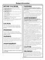
BEFORE YOU BEGIN
WARNING:
Read
TO REDUCE THE RISK OF HRE, ELECTRICAL
SHOCK OR INJURY TO PERSONS, OBSERVE THE
FOLLOWING:
A. Use tiffs unit only in the manner intended by the
manufacturer.
If you have any questions, contact the
these
instructions
completely
" IMPORTANT
local inspector's
and
carefully.
- S.vethese instructionsfor
use.
• IMPORTANT
•
•
•
•
•
•
- Observe
.ll governing codes
and ordinances.
Note to Installer - Be sure to leave these instructions
with the Gonsumer.
Note to Consumer - Keep these instructions for
fitture reference.
Skill Level - Installation of this vent hood requires
basic mechanical and electrical skills.
Completion time - 1 to 3 hours.
Proper installation is the responsibili D, of the installer.
Product failure due to improper installation is not
covered under the _¥arranty.
InaI]
AVERTISSEMENT
Due to the weight and size of tiffs vent hood and to
reduce the risk of personal
ii_jury or damage
to the
product,
we recommend
at least three people install
this hood.
• For general ventilating use only. Do not use to exhaust
hazardous or explosive materials or vapors.
• Structural flaming, installation work and electrical
wiring must be done by qualified person (s). In
accordance with all applicable codes and standards
including fire-rated consuucfion.
• Sufficient air is needed for proper combustion and
exhausting of gases through the flue (chimney) of fuel
burning equipment to prevent back drafting. Follow
the heating equipment manufacturer's
guideline and
safety standards such as those published by the
National Fire Protection Association (NFPA), and the
American Society for Heating, Refligerafion and Air
Conditioning Engineers (ASHRAE), and the local
code attthorifies.
• I,ocal codes vary. Installation elecuical connections
and grounding must comply with applicable codes.
In the absence of local codes, tim vent should be
installed in accordance with National Elecuical (;ode
ANSI/NFPA 70-1990 or latest edition.
PRUDENCE:
du poids
et de la mille de la hotte
et pour
r_duire les risques de blessures
ou de dommages
de
l'dquipement,
nous recommandons
que trois personnes
installent
cette hotte.
WARNING:
To reduce the risk of fire or electrical shock, do not use
tiffs range hood with any external solid-state speed
conuol device. Any such alteration flom original factory
wiring could result in damage to the unit and/or create
an electrical safety hazard.
AVERTISSEMENT
:
Pour rdduire le risque d'incendie
ou de choc 41ecuique,
il tie faut pas u6liser cette hotte avec un rdgulateur
de
vitesse dlectronique
externe.
Toute modification
de ce
type du branchement
d'usine
peute endommager
l'appareil
ou crder un risque de choc dlecuique.
TO REDUCE
DUCTWORK.
THE
RISK OF FIRE, USE ONLY
:
POUR RI_DUIRE LE RISQUE D'INCENDIE, DE
CHOC I_LECTRIQUE OU DE BLESSURES, IL FAUT
OBSERVER LES REGLES SUIVANTES :
A. Ufiliser cet appareil uniquement
de la mani_re
pr_vue pax le fabricant. En cas de question, consulter
le fabricant.
B. Avant toute intervention
ou nettoyage, couper
l'alimentafion
dlecuique au disioncteur et
verrouiller le panneau du disjoncteur pour dviter la
mise sous tension accidentelle. S'il n'est pas possible
de verrouiller le panneau du disconcteur, atmcher
un placard ou une _fiquette u_s visible au panneau.
CAUTION:
]_ cause
tl fac tit re t.
B. Before servicing or cleaning unit, switch power off at
the service panel and lock service panel to prevent
power flom being switched on accidentally. If the
service panel cannot be locked, fasten a mg or
prominent warning label to the panel.
CAUTION:
t-ed.ce
t-isk
o .tea.dto
properly exhaust air, be sure to duct air outside--Do
not vent exhaust air into spaces within walls or ceilings
or into attics, crawl spaces, or garages.
METAL
PRUDENCE •• I1faut
prendre soin
d'insmller un conduit vers l'ext_rieur pour r_duire le
risque d'incendie et pouvoir _vacuer l'air correctement.
I1 ne faut pas _vacuer l'air correctement.
I1 ne faut pas
_vacuer l'air dans l'espace enue les parois d'un i_lttr,
un plafond ou un greniet, un espace sanitaire ou un
garage.
2
Design Information
CONTENTS
Design Information
Product Dimensions
.........................................................
Duct Cover Accessories
................................................
Determine
Installation
Height
........................................
Advance Planning
Tools and Materials Required ..........................................
Power Supply ....................................................................
Duct Fittings ......................................................................
Installation
Instructions
Step 1, Consuuct
Ceiling Support ...............................
Step 2, Remove Packaging
.............................................
PRODUCT
Step
Step
Step
Step
Step
Step
Step
Step
Step
Step
3
3, 4
4
5
5
6
7-9
10
DIMENSIONS
3, Check Insudlation Hardware
.............................
4, Mount Template
.................................................
5, Install Support Frame ........................................
6, Secure Wiring .....................................................
7, Size and Install Ductwork
..................................
8, Install Decorative
Duct Covers ..........................
9, Install Hood ........................................................
10, Connect
Elecuical
............................................
11, Slide Duct Cover Down ....................................
12, Install Filters, Finalize Installation
..................
10
11
11
12
12
13
13
14
14
15
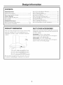
DUCT COVER ACCESSORIES
A Duct Cover Accessory
may be required
for your hood
installation
height. Order Accessory duct covers for 9 ft.
and 10 ft. ceilings.
This vent hood is designed
to be used in vented ceiling
mounted
installations.
It can be installed
over any
Monogram
cooktop
or range, including
Professional
models.
ZX1059SFSS
- For9 ft. ceiling height
This kit includes
a decorative
duct cover and support
frame to reach a 9 ft ceiling height.
ZXl0510SFSS
- For 10 ft. ceiling height
This kit includes
a decorative
duct cover and support
frame to reach a 10 ft ceiling height.
* 20"to an 8 ft, ceiling using supplied duct cover
32" for 9 ft, ceiling using ZX1059SFSSAccessory
44"for 10ft. ceiling using ZX10510SFSSAccessory
This vent hood is supplied
with a decorative
duct cover
to reach 8 ft. ceiling height, or between
7'11" and 8'1".
3
Design Information
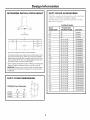
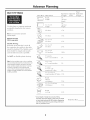
DETERMINE
INSTALLATION
HEIGHT
DUCT COVER ACCESSORIES
Order the accessory at the same time as the vent hood
and have on site before installation begins.
Use this chart to accurately determine the need for a
Duct Cover Accessory.
InstallationHeights
Actual
L_
.... m ....
_J I
*30"
Recommended
*Possible Hood
Ceiling Height
InstallationHeight
Duct Cover
7'11"
29"
Supplied
8'0"
30"
Supplied
8'1"
30"
Supplied
o
o
8'2"
25-1/2"to30"
ZX1059SFSS
o
o
8'3"
25-1/2"to30"
ZX1059SFSS
o
8'4"
25-1/2"to30"
ZX1059SFSS
o
8'5"
25-1/2"to30"
ZX1059SFSS
8'6"
25-1/2"to30"
ZX1059SFSS
8'7"
25-1/2"to30"
ZX1059SFSS
8'8"
25-1/2"to30"
ZX1059SFSS
8'9"
25-1/2"to30"
ZX1059SFSS
8'10"
25-1/2"to30"
ZX1059SFSS
8'11"
25-1/2"to30"
ZX1059SFSS
9'0"
25-1/2"to30"
ZX1059SFSS
9'1"
25-1/2"to30"
ZX10510SFSS
9'2"
25-1/2"to30"
ZX10510SFSS
9'3"
25-1/2"to30"
ZX10510SFSS
9'4"
25-1/2"to30"
ZX10510SFSS
9'5"
25-1/2"to30"
ZX10510SFSS
9'6"
25-1/2"to30"
ZX10510SFSS
9'7"
25-1/2"to30"
ZX10510SFSS
9'8"
25-1/2"to30"
ZX10510SFSS
9'9"
25-1/2"to30"
ZX10510SFSS
9'10"
25-1/2"to 30"
ZX10510SFSS
9'11"
25-1/2"to 30"
ZX10510SFSS
10'0"
25-1/2"to 30"
ZX10510SFSS
[
*9 ft. to 10ft. ceilings may be 25-1/2"to 30" clearance.
The distance between the cooking surface and the bottom ofthe
hood must be at least 25-1/2".The 30"recommended installation
height, above the standard 36" countertop, will insure duct cover
fit to the ceiling. For 9ft. and 10ft. ceiling heights, the hood may
be lowered to 25-1/2"over the cooking surface.
*When installing the Island Hood above a Monogram Professional
Range or Cooktop, installation clearance must be at least 30".
IMPORTANT:Clearances may vary due to type of cooking product
and local codes. Check with local inspectors to be sure standard
is applicable.
DUCT COVER DIMENSIONS
ZVl050 Duct CoverDimensions
A
B
ZV1050
11-1/2"
12"
ZX1059
19"
20"
ZX10510
25"
26"
4
Advance Planning
TOOLS AND MATERIALS
REQUIRED
POWER SUPPLY
(not supplied)
• Tapemeasure
• Knife
• Spirit level
• Wire cutter
• Wire stripper
• Wire nuts
• Electric drill and 5/32" bit
• Phillips screwdriver
• Flat blade screwdriver
• Hammer
• Pliers
• Safety glasses
• Tapeto mount template
• Gloves to protect against sharp edges
• 120V60Hz, 15 or 20 Amp, 2wire with ground, properly grounded
branch circuit
• Strain relief for junction cover
• Plumb bob
• Center punch
IMPORTANT
- Please
read
carefully.
WARNING: , ORP ON
THIS APPLIANCE MUST BE PROPERLY GROUNDED.
ATTENTION
•• POUR
DES RAISONS
DE SI_CURITI_, CET APPAREIL DOlT I_TRE
CORRECTEMENT MIS A LA TERRE.
Remove house filse or open circuit breaker
beginning installation.
before
Do not use an extension cord or adapter plug with this
appliance. Follow National Electrical Code or prevailing
local codes and ordinances.
Electrical supply
This vent hood must be supplied with 120V, 60Hz, and
connected to an individual, properly grounded branch
circuit, and protected by a 15 or 20 amp circuit
breaker or time delay fiase.
• Wiring must be 2 wire with ground.
• If the electrical supply does not meet the above
requirements,
call a licensed elecuician before
proceeding.
• Rotate house wiring in the ceiling, as close to the
installation location as possible. Allow an additional
3 feet length flom ceiling joists to reach the junction
box on tim hood.
• Connect the wiring to the house wiring in accordance
with local codes.
Grounding
instructions
The grounding
conductor
must be connected
to a ground
metal, permanent
wiring system, or an
equipment-grounding
terminal
or lead on the hood.
WARNING: l,e mp ope
connection
of
equipment-grounding
conductor can result in a risk of
elecuic shock. Check with a qualified electrician or
service representative
if you are in doubt whether the
appliance is properly grounded.
AVERTISSEMENT
:
I,e mauvais branchement
du fil de raise _ la terre peut
causer un choc _lecuique. En cas de doute, consulter
un _lecuicien qualifi_ ou un teclmicien pour
d_terminer si l'appareil est _ la terre.
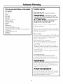
Advance Plannin
Total
Duct
Piece
Equivalent
Length*
Dimensions
Quantity
Used
Equivalent
Length
Round,
Use
this
permissible
chart
to compute
lengths
for
straight
(per toot
length)
3-1/4" x 12"
straight
(per toot
length)
90 ° elboB
17 ft.
45 ° elb(m
I 0 ft.
90 ° elbo_
3-1/4" x 12"
43 ft.
45 ° elb{}_
3-1/4" x 12"
26 ft.
90
3-1/4"
° fiat x elboB
12"
102 it.
Q
3-1/4" x 12" transition
8" round to
2 It.
_lt,
to
8" round
3-1/4"
x 12" transition
5 it.
to 3-1/4"
8" I'Ot/lld
transiti(}n
6 ft.
maximum
duct
runs
to
otltdooI's.
Note: Do not exceed maximum ?ermissible
equivalent lengths!
(_
Maximum duct length:
100ft. for range hoods.
Flexible ducting:
If flexible metal ducfing is used, all
the equivalent
feet values in the table
should be doubled.
The flexible metal
duct should be straight
and extended
as much
Do NOT
use flexible
and smooth
as possible.
plastic
ducfing.
Note: Any homeventilation system,suchasa ventilation
hood,may interruptthe properflow of combustionair and
exhaustrequiredbyfireplaces,gas furnaces,gas water
heatersandother naturallyvented systems.To minimize
the chanceof interruption of such naturallyvented
systems,follow the heatingequipmentmanufacturer's
guidelinesandsafety standardssuchasthose published
byNFPAandASHRAE
_
_
x 12"
90 ° elb(m
r(}und transiti(}n 90 ° elb(m
3-1/4" x 12" to 8"
1: ft.
3 "
_%allcap
s_ith damper
3-1/4"
Bith
32 ft.
x 12" Ball cap
dan}per
Round
roof cap
75 ft.
44 it.
*Actual length of straight duct plus duct fitting
equivalent. Equivalent length of duct pieces are based
on actualtests conductedby GEEvaluationEngineering
and reflectrequirementsfor good venting performance
with any ventilation hood.
Total
Duct
Run
Installation
Instructions
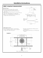
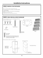
[STEP 1 ] CONSTRUCT CEILING SUPPORT
Ceiling
Plan the location
Determine
the exact
Hood
location
of the vent
hood.
Centerline
• Use a plumb bob to check location
to be sure
countertop/cooktop
location
below the hood will
align exactly.
• The hood should project forward
1-1/2" beyond the front
edge of the cooking
appliance.
See illustration.
• Observe
the recommended
space (30") between
the
cooking
surface and bottom
of hood.
Front
31-1/2" i..................................................................
Approx.1-1/2''_ *ii
BeyondCooking I
Surface
,
f_
-
Cooktop
I Countertop
SideView
Ceiling support structure
• At the hood location, install 2 x 4 cross flaming
between ceiling joists as shown. (2x4s are required
to support the weight of the hood.)
• Arrange cross flaming in the ceiling to suit the
existing structure.
• Your ceiling joists will be like one of the following
examples.
EXAMPLE A
I
11-1/4"Install Cross-Framing
SymmetricallyAbout
Duct/CooktopCenterline
1
16"Joist
Spacing
I
i
i
i
i
__
i
i
iii
iiii_iii
i
4----
--
',iii
i
i
i
i
--
2x4 Cross
Framing
i
I
I
i
i
Align Ductto Center
of Cooktop
Front
of Hood
TopView--Ceiling Joists Parallelto Frontof Hood
't
Cooktop
Outline
Installation
Instructions
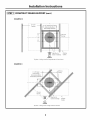
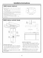
[STEP 1 ] CONSTRUCT CEILING SUPPORT (cont.)
EXAMPLE B
|
16"Joist
Spacing
11-1/4"InstallCross-Framing
SymmetricallyAbout
2x4 Cross
\ Framing
\
Align Ductto
Centerof Cooktop
Cooktop
Outline
Front
of Hood
TopView--Ceiling Joists RunPerpendicularto Frontof Hood
EXAMPLE C
2x4Cross
Framing
11-1/4"Install
Cross-Framing
SymmetricallyAbout
Duct/CooktopCenterline
i 1
16"Joist
Spacing
Align Ductto
Centerof Cooktop
Front
of Hood
TopView--Ceiling Joists at Anglewith Frontof Hood
\
Cooktop
Outline
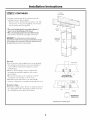
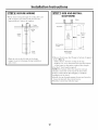
Installation
Instructions
2x 4 Min.
CrossFraming
I STEP 11CONTINUED
N
.........
• Arrange cross flaming in the ceiling to suit the
existing suuculre. See examples.
- Secure each 2 x 4 block with at least four (4), #10
wood screws, 3" long (not supplied). Use 8 wood
screws total for the two supports.
'-
d
Ceiling'/
• The cross framing must be accurately
aligned to
assure correct positioning
of the hood.
• The cross framing must be level in all directions.
Check with a spirit level and adjust if necessary.
g? 7-1/411_
JO, t ,
..I-- II /I Frar_e
°72(/
IMPORTANT:The ceiling structure must be capable of
supporting the weight of the hood (approximately 300 pounds) and
any inadvertent user contact loads. The hood support frame will
be supported bythe 2x4 rain. cross framing.
F_nt
OfSupport
_0penlng
I Hood
/
I.._.._ i
_"_--_
Ductwork
I
A!"-Height
: Adjustment
,,:c:__--:a
=
=
i
• Use the shortest and suaightest duct route possible.
For satisfactory performance,
duct run should not
exceed 100 feet equivalent length for any duct
configuration.
• Refer to "Duct Fittings" chart to compute the
maximum permissible length for duct runs to
the outdoors.
• This vent hood must use 8" round duct. The 8"
round duct can transition to 3-1/4" x 12".
• Install the house ductwork to run horizontally
between ceiling joists or straight up through the roof.
/
i
=
i
CeilingJoist
,=
/
i
=
',
8"
i Duct !_Y_
L____J........
&
2x4
Vent StraightUp
ThroughThe CeiJiug
DuctElbow
Finish the Ceiling
• Finish the ceiling surface. Be sure to mark location of
the ceiling joists and cross flaming. Check to be sure
the ceiling is level; use shims, if necessary.
\
Standing
_
*Depending on available space.
9
*Vent Between
Ceiling Joists
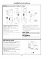
Installation
Instructions
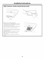
ISTEP 21 REMOVE THE PACKAGING
The vent hood is packed separately flom the
decorative duct cover or accessory covers ZX1059SFSS
or ZX10510SFSS.
• Remove the flame, cover, parts box and packaging.
• Remove junction box cover.
• Install suain relief onto junction box coveL
[STEP 3 CHECK INSTALLATION
I,ocate the hardware
hood
and
check
accessory pack shipped
HARDWARE
with the
contents.
3 Phillips head decorative screws
Template
4 Machine Screws
©
4 Lock Washers
4 Filters
4 Hex Head
Lag Screws
Service Safety
Stop Screw
Check service manual envelope taped to the side
of the hood to be sure it contains one stop screw.
Leave this screw in the envelope.
Gheck
contents
of the accessory
package.
MountingScrewHoles
1
Support frames
with 8 screws
and 8washers
Decorative Duct Covers
o
\Attachment
ScrewHole(LeftSide)
10
Installation
ISTEP 4 ] MOUNT
Instructions
TEMPLATE
• Align the template with tile marks on tile ceiling and
rope in place.
- Be sure tile template is oriented correctly, with tile
flont of tile hood.
• Use a phnnb bob to be sure the mounting holes will
provide parallel alignment with tile countertop below.
• Center punch all hole locations.
• Drill pilot holes in tile 4 screw locations. Use a 5/32"
bit and drill approximately
1-1/2" deep.
• Gut tile 8-1/4" duct opening and approx. 1" wire
access hole.
,_ssHoles
ISTEP51 INSTALL SUPPORT FRAME
_o°dnting
_Lower
Flang
e __
I
_1 ......
Support
.....................
'
40"
30"Recommended
76"
Upperz
Support
Frame
Lower
Support
Frame
Support
Frame
Opening
Countertop
_CheckLevel
in
Both Directions
Install lower support frame
• Insert lower support flame (or accessory support
flame, ZX1059SFSS or ZX10510SFSS) into the upper
support flame and loosely secure with 8 screws and
washers (4 on the flont and 4 on tile back sides).
• Adjust tile lower support flame up or down to tile
desired height above tile countertop.
Tighten screws.
Install upper support frame
• Secure tile upper support flame to tile ceiling joists
and cross flaming with tile 4 lag screws provided. For
maxinlum rigidity and strength, tile screws must be
driven into tile center of the joists and/or cross
flaming.
Check to be sure the support frame is level, vertically
and horizontally.
IMPORTANT: Again, check to be sure tile support
is level in both directions. There is no way to level
tile hood after tile hood is secured to tile flame.
11
Installation
Instructions
[STEP 6 SECURE WIRING
• Route house
pull a length
approximately
wiring through
the ceiling
to reach the hood junction
6" below the support.
STEP 7 SIZE AND INSTALL
DUCTWORK
hole and
box,
:
_/_ i,
i
Celing
/
Ceiling
/
,
i
i
.
HouseDuct....
_C,
LeftSide
View
m
Support_.
Frames " "-
:L[__
!
""-' _'",Req
Side
View
Support
Frame
\
\\
Duct
Dim.A
ired
Duct
Lenth
\
}Tape
DuctConnection
ToHood ....
/
/
/
/
----___
House
Wiring
BottomSupport
Frame
Flange
• Measure
flom house
frame (Dim. A).
• Tape the wire to the left side of the flame
support
to prevent
damage
during installation
and service.
duct
flange
to bottom
of support
- Add at least 1" for duct overlap at the top.
- Subuact
1-3/4" for hood insertion
into the bottom
of the flame to determine
required
duct length.
• Cut the 8" duct length
required.
NOTE: The bottom of the duct must be external
(female)
connection
to the top of the hood. The
bottom end should be flared slightly, to facilitate
installation
of the hood.
• Install duct up through
support
flames
house ducfing with sheet metal screws.
• Seal the comlec6on
with duct tape.
12
and attach
to
Installation
Instructions
I STEP 81 INSTALL DECORATIVE DUCT COVERS
InstallScrewon
EachSide
\\\
Pretap
2 Screw
Holes
(One
On
Each
Side)
BottomDuctCover
BottomDuct
Cover
!
o
Top Duct
Cover
Stop _
Screw o=a
\...
Install Stop
Screw in Hole
A/
of Upper (Inner)
Duct Cover
• Pretap or drive decorative screw into the screw
holes on the support frame. This will make screw
installation easier.
• Slide the lower decorative
• Separate the two decorative duct covers.
• Select the inside covet (top), which has two screw
holes in the top.
• Slide the decorative duct covet over the support
flame and push to the ceiling.
• Attach to the hood support at the top with 2 supplied
decorative screws.
• I,ocate the 3rd decorative screw in the hardware
• Install the decorative stop screw in center hole of
upper (inner) duct covet. The decoraOve screw will act
as a stop screw and prevent the lower decorative duct
covet from sliding down.
package.
duct over the installed
upper duct and push to the top, keeping
slotted hole to the left.
the bottom
CAUTION: The
stop
sc,e,v
re.st
t.
Failure to do so could
to the duct covet.
result
in personal
i_ju D, or damage
Set aside.
PRUDENCE :
en place, afin d'_viter
le capot antipoussi6re.
dolttte
les blessures
ou d'endommager
ISTEP91INSTALL HOOD
Bottom
Duct
Cover
NOTE: AT LEAST THREE PEOPLE ARE REQUIRED
TO COMPLETE
THIS INSTALLATION!
• I,iff the hood tap to the support
flame. Careflflly align
the hood mounting
holes to support
flame holes, and
at the same time, the hood duct connector
into the
duct.
• Install
• Check
screws through
the hood and
hood level in both directions.
• Check to be sure
hood connector.
• Seal the duct
that
connection
the duct
hood
is positioned
with duct
_Stop Screw
Install
4LockWashers
and4 MachineBolts
support.
Apply DuctTape
to Seal Duct
Connection
over the
tape.
Note: Do not drive screws through this duct connection.
Doing so will prevent proper damper operation.
13
Installation
STEP 10 CONNECT
Verify
that power
is turned
WARNING:
Instructions
STEP 11 SLIDE DUCT COVER DOWN
ELECTRICAL
off at the source.
fl,o.se
wi,-ins.ot
with a ground wire, a ground
must be provided
by the
installer. When house wiring is aluminum,
be sure
to use UL approved
anti-oxidant
compound
and
aluminum-to-copper
connectors.
Install
Decorative
Screw
,_
AVERTISSEM ENT : silec ,bl ,ge
de la maison n'est pas du type f, deux ills avec un fil
de terre, l'installateur
dolt fournir
un circuit de terre.
Quand les ills de la maison sont en aluminium,
il prendre
soin d'ufiliser
de la piite antioxidafion
approuv_e
par UL et des connecteurs
pour
l'aluminium-cuiwe.
• Install
box
strain
relief
onto
the knockout
• Hold the decorative
of the junction
coveI;
• Insert house wiring through
strain relief and tighten.
• Connect
white leads to branch
circuit white lead.
• Connect
black leads to branch
circuit black lead.
• Connect
green/yellow
or bare ground
lead.
• Secure all connections
electrical
connectoL
leads
to branch
circuit
green
with wire nuts on each
• Push wires into junction
box and replace
Be sure wires are not pinched.
duct cover and remove
the
decorative stop screw flom the support flame.
Keep the screw.
• Slide the lower duct cover down onto the hood.
• Install the decorative screw in the lower left hole on
the duct cover as shown.
coveL
14
Installation
STEP 12 INSTALL FILTERS, FINALIZE
Instructions
INSTALLATION
FilterSlots
• Remove protective
film on tile filters.
• Tip tile filter into tile lower slots at tile rear of tile
opening.
I,ift tile filter and pull tlle knob forward
until tile filter rests on tlle slots.
• To remove tile filters, grasp tile knob and push
filter towards tlle rear and tilt downwards.
tile
• Remove tlle protective film covering tile conuol
panel on tile flont face of tile hood, and any other
packaging materials.
• Gheck all 4 lamps to assure tightness in sockets.
• Refer to tile Owner's Manual for operating
instructions.
• Glean tile hood with an approved
cleaner.
stainless steel
15
Note: While performing installations described in this book,
safety glasses or goggles should be worn.
For Mo_wg,ram _°local ,_÷_vic_in yo_tr ar_a, call
1.800.444.
1845.
Note: Prod uct improvement
is a conthluhlg
endeavor
at
(;enera] Electric. Therefbre,
materials, appearance
and
specifications
are subject to change _ithout notice.
Monogram:
Pub.No.49-80153-2
11-07 JR
GEConsumer & Industrial
GEAppliances
General Electric" Company
Louisville, KY 40225
ge.com
Printed in Italy
@2007 GE Company