1
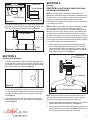
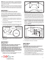
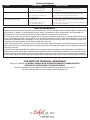
IMPORTANT INSTRUCTIONS OPERATING MANUAL
Models: AIK14X, AIK16X, AIK24Y, AIK26Y,
AIF4X, AIF6Y, AIF8X, AIF10X,
AIG4, AIG6
In-Line Exhaust Fan
READ AND SAVE THESE INSTRUCTIONS
READ CAREFULLY BEFORE ATTEMPTING TO ASSEMBLE, INSTALL, OPERATE OR MAINTAIN THE PRODUCT DESCRIBED. PROTECT
YOURSELF AND OTHERS BY OBSERVING ALL SAFETY INFORMATION. FAILURE TO COMPLY WITH
INSTRUCTIONS COULD RESULT IN PERSONAL INJURY AND/OR PROPERTY DAMAGE!
RETAIN INSTRUCTIONS FOR FUTURE REFERENCE.
GENERAL SAFETY INFORMATION
When using electrical appliances, basic precautions
should always be followed to reduce the risk of fire,
electric shock and injury to person, including the following:
WARNING: DO NOT CONNECT POWER SUPPLY UNTIL FAN
IS COMPLETELY INSTALLED. MAKE SURE ELECTRICAL SERVICE
TO THE FAN IS LOCKED IN OFF POSITION.
1. Read all instructions before installing or using exhaust fan.
2. Use this unit only in the manner intended by the manufacturer.
If you have questions, contact the manufacturer.
6. When cutting or drilling into wall or ceiling, do not damage
electrical wiring and other hidden utilities.
7. Ducted fans must always be vented to the outdoors.
8. To avoid motor bearing damage and noisy and/or unbalanced
impellers, keep drywall spray, construction dust, etc. off
power unit.
3. Before servicing or cleaning the unit, switch power off at
service panel and lock the service disconnecting means to
prevent power from being switched on accidentally. When
the service disconnecting means cannot be locked, securely
fasten a prominent warning device, such as a tag, to the
service panel.
9. Acceptable for use over a bathtub or shower when installed
in a GFCI protected branch circuit.
4. Installation work and electrical wiring must be done by
qualified person(s) in accordance with all applicable codes
and standards, including fire-related construction.
12. Guards must be installed when fan is within reach of personnel
or within seven (7) feet of working level or when deemed
advisable for safety.
5. Sufficient air is needed for proper combustion and exhausting
of gases through the flue (chimney) of fuel burning equipment
to prevent back drafting. Follow the heating equipment
manufacturer’s guideline and safety standards such as those
published by the National Fire Protection Association (NFPA)
and the American Society for Heating, Refrigeration, and Air
Conditioning Engineers (ASHRAE), and the local code authorities.
13. NEVER place a switch where it can be reached from a tub or
shower.
10. Suitable for use with solid-state speed control.
11. This unit has rotating parts and safety precautions should be
exercised during installation, operation and maintenance.
14. Do not insert or allow fingers or foreign objects to enter the
motor.
WARNING: DO NOT USE IN KITCHENS
CAUTION: FOR GENERAL VENTILATING USE ONLY. DO
NOT USE TO EXHAUST HAZARDOUS OR EXPLOSIVE MATERIALS
AND VAPORS.
SAVE THESE INSTRUCTIONS
5S7635036 New 9-06
1 of 12
INSTALLATION INSTRUCTIONS
CAUTION: MAKE SURE POWER IS SWITCHED OFF AT
SERVICE PANEL BEFORE STARTING INSTALLATION.
Fan
SECTION 1
Preparing for Fan Installation
1. When selecting fan mounting location, the following criteria
should be considered:
a) Mounting to minimize noise generated by fan operation:
Mounting the fan as far as possible from the intake
point will minimize fan operating noise from being
transmitted back through the duct work. If the fan is to
be used as a booster for moving the air between two
rooms, a central point along the duct may be optimal.
Insulated flexible type duct work (recommended for all
bathroom exhaust applications) will result in much
quieter operation. It is recommended that a minimum
8' of insulated flexible ducting be used between any
exhaust grill and fan for low noise level.
b) Service accessibility: Fan location should allow
sufficient access for service.
Stud
Figure 2
Screws
Bracket
NOTE: Bracket is provided with rubber vibration isolation grommets
to prevent the transmission of sound through the structure. Be
careful not to over tighten. Also, care should be taken not to strip
the plastic housing. Screws are self tapping and do not require
pilot holes. Pilot holes no larger than 1/16" can be used to ease
the installation however.
SECTION 3
Installing Supply/Exhaust Grill
SECTION 2
Installing the Fan
1. Using the 1" wood screws provided, attach the fan mounting
bracket to a support beam at the selected location (Figure 1).
Vertical Mounting
Horizontal Mounting
Bracket
Bracket
or
2. Bend the mounting straps attached to the collar outward so
they are straight across (Figure 3).
Stud
Figure 1
1. Select the grill mounting point within the area to be ventilated
that does not interfere with a ceiling joist. To ease installation,
locations of framing beams within the walls or joists supporting
the ceiling should be considered. Collar/damper is provided
with a perforated hanging strap for attachment directly to a
beam or joist. Allow sufficient space between the collar/damper
and the beam to attach the duct work. If the location of the
grill does not allow direct attachment, a cross-member mounted
to the framing should be used.
Joist
NOTE: Fan mounting can be at any point along the duct and in
any angle, however, vertical mounting is recommended to reduce
condensation buildup in the fan. If a horizontal installation is
necessary and condensation buildup may pose a problem, wrap
insulation around the fan to minimize buildup.
2. Attach fan to the mounting bracket with the three 7/16" sheet
metal screws provided, making sure the wiring box is
positioned for easy access (Figure 2).
Mounting
Strap
Mounting
Strap
Figure 3
Collar/Damper
SECTION 4
New Construction
1. Install the collar/damper in the selected location using the
provided 1" wood screws through the mounting strap. The
mounting height is determined by the thickness of the final
wall/ceiling material. Ensure that the edge of the collar/damper
will be flush with the finished wall/ceiling material (Figure 4).
5S7635036 New 9-06
2 of 12
Joist/Stud
Joist/Stud
SECTION 6
Collar/Damper
CAUTION: ALL DUCTING MUST COMPLY WITH LOCAL
Ducting
AND NATIONAL BUILDING CODES.
Screws
Collar/Damper
Wall/Ceiling Material
Figure 4
2. Once the wall/ceiling material is in place, install the grill into
the collar by pushing it firmly inward towards the collar until
it fits flush against the wall/ceiling material (Figure 5).
Collar/Damper
Grill
Figure 5
NOTE: Insulated ducting is required for bathroom exhaust
applications, where ducting passes through unconditioned space
or where noise is a factor. Failure to use insulation could result
in excessive condensation buildup within the duct, and
undesirable sound levels within the room. Duct runs should have
as few bends as possible.
NOTE: Flexible insulated ducting may be used where allowed
by local code. For the quietest possible installations, it is
recommended a minimum of 8' of insulated flexduct be used
between any exhaust grill and fan. When using flexible type
duct work, duct should be stretched as tight and straight as
possible. Failure to do so could result in dramatic loss of system
performance. Flexible duct should be connected to the fan with
screw clamps or duct tape. All connections should be as airtight
as possible to maximize system performance.
1. Connect one end of the ducting (not included) to the room
level collar/damper and the other end to the “Y” transition.
Secure both ends in place using tape or a screw clamp to
create as air tight a seal as possible. Repeat this step for the
other room level grill housing (Figure 7).
Exhaust to
Wall/Roof Cap
SECTION 5
Existing Construction
1. Place the collar/damper in the selected location and trace
a circle onto the surface. From the interior side of the room,
cut through the surface. Please note: Take care not to damage
the ceiling and make a smooth cut (Figure 6).
Fan
“Y” Transition
Figure 6
2. Position the collar/damper in the previously cut hole so that
it is flush with the finished ceiling and secure to the joist/stud
using the provided 1" wood screws through the mounting
strap (Figure 4).
3. Install the grill into the collar by pushing it firmly inward
towards the collar until it fits flush against the wall/ceiling
material (Figure 5).
Ducting
Collar/Damper
Figure 7
NOTE: Units that include only one collar do not utilize the “Y”
transition. Follow the same instructions as in step 1, except
connect the one end of the ducting directly to the fan.
2. Connect one end of the ducting to the top of the “Y” transition
and the other end to the intake of the fan (Figure 7).
3. Connect one end of the ducting to the exhaust of the fan and
the other end to a wall or ceiling cap (Figure 7). Always duct
the fan to the outside through a wall or roof cap.
5S7635036 New 9-06
3 of 12
NOTE: When using insulated flex duct, it is recommended that
the inner vinyl core be screw clamped or taped to the inlet and
outlet and that the vapor barrier surrounding the insulation be
taped to the fan housing.
Screws
NOTE: When attaching flex duct to the collar/damper combination
and an immediate elbow is necessary, be certain that the elbow is
installed with a "soft" bend to allow damper blades to operate properly.
Terminal Box
SECTION 7
Figure 9
Installing Optional Balancing Damper
Some kits include an optional balancing damper to allow for
adjustment of the system. The damper may be used where the
grills will be connected using branches of unequal length or
where the flow will need to be balanced for any reason. To Install
the optional damper:
2. Run wiring from an approved wall switch carrying the
appropriate rating. One neutral (white) and one hot (black
lead connected to the switch). Secure the electrical wires
to the housing with an approved electrical connector. Make
sure you leave enough wiring in the terminal box to make the
connections to the fan’s pre-wired electrical terminal strip.
1. The damper must be installed on the branch with the least
restriction. This is generally the duct that is shortest or has
the fewest bends.
3.
2. Drill a 5/16" hole approximately 1-1/2" from the edge on the
flat side of the “Y” transition.
3.
Insert the shaft of the damper into the hole drilled in step 2. Place
the washer, handle, then wing nut onto the shaft (Figure 8).
Insert the white wire from the house into the terminal strip port
labeled “N” and tighten using a small regular screwdriver. Insert
the black wire from the wall switch into the terminal strip port
labeled “L” and tighten using a small regular screwdriver. Since
the motor is isolated within a plastic housing, grounding is not
necessary (Figure 10).
Supply from house
Wing Nut
Handle
Washer
White
Shaft
Hole
Blue
N
L
Damper
Red
“Y” Transition
Figure 8
4. Adjust the damper to balance airflow and tighten the wing
nut to secure.
Brown
Black/Red
Black
Figure 10
4. Check to make sure all wire connections are securely fastened
to the terminal strip and replace the fan terminal box cover.
5. Restore power and test your installation.
SECTION 8
Wiring the Fan
CAUTION: MAKE SURE POWER IS SWITCHED OFF AT
SERVICE PANEL BEFORE STARTING INSTALLATION.
CAUTION: ALL ELECTRICAL CONNECTIONS MUST BE MADE
IN ACCORDANCE WITH LOCAL CODES, ORDINANCES, OR
NATIONAL ELECTRICAL CODE. IF YOU ARE UNFAMILIAR WITH
METHODS OF INSTALLING ELECTRICAL WIRING, SECURE THE
SERVICES OF A QUALIFIED ELECTRICIAN.
1. Remove the screws securing the terminal box cover plate
located on the side of the motor (Figure 9).
5S7635036 New 9-06
SECTION 9
Use and Care
CAUTION: MAKE SURE POWER IS SWITCHED OFF AT
SERVICE PANEL BEFORE SERVICING THE UNIT.
1. Cleaning the Grill: Remove grill and use a mild detergent,
such as dishwashing liquid, and dry with a soft cloth. NEVER
USE ANY ABRASIVE PADS OR SCOURING POWDERS.
Completely dry grill before reinstalling. Refer to instructions
in Step 2 of Section 4, to reinstall grill.
2. The fan’s bearings are sealed and provided with an internal
lubricating material, no additional lubrication is necessary.
4 of 12
Troubleshooting Guide
Trouble
Probable Cause
Suggested Remedy
1. Fan does not operate when the switch is on.
1a. A fuse may be blown or a circuit tripped.
1b. Wiring is not connected properly.
1c. Motor has stopped operating.
1a. Replace fuse or reset circuit breaker.
1b. Turn off power to unit. Check that all wires are connected.
1c. Replace motor.
2. Fan is operating, but air moves slower than normal.
2a. Obstruction in the exhaust ducting.
2a. Check for any obstructions in the ducting. The most common are bird nests
in the roof cap or wall cap where the fan exhausts to the outside.
2b. If a speed control is being used, confirm the setting.
2c. Turn off power to unit. Check that all wires are connected correctly.
2b. Speed control not set high enough.
2c. Incorrect wiring.
3. Fan is operating louder than normal.
3a. Motor is loose.
3a. Turn off power to unit. Confirm unit is mounted securely to bracket.
Restore power to unit.
3b. Fan mounting screws too tight.
3b. Turn off power to the unit. Loosen screws going through rubber grommets
3c. Fan damaged in shipping.
3c. Contact seller for replacement.
LIMITED WARRANTY
All products manufactured by Air King Limited are warranted for one year from the date of purchase against defects in workmanship
and/or material. In addition, all ventilating/exhaust fans, heaters, combination fan lights and/or heaters, and range hoods are
guaranteed for five years from the date of purchase against defects in workmanship and/or material.
This warranty does not cover any labor or shipping costs or the cost of replacement components as part of routine maintenance
such as: range hood grease filters, charcoal filters or combination charcoal/grease filters; replacement light bulbs in range hoods
or bathroom fan/light/bulb heater combinations. As well, any damage or failure caused by abuse, misuse, abnormal usage, faulty
installation, or improper maintenance will not be covered by this warranty.
In order to make a claim on this warranty, you must be the original consumer of the product. You will be required to present to Air
King the original bill of sale showing: date of purchase, place of purchase and model purchased. Failure to meet these requirements
will void your warranty.
Air King will not be held responsible for any bodily injury or damages to personal property or real estate whether caused directly or
indirectly by the product. Some states and provinces do not allow the exclusion or limitation of incidental or consequential damages
and some states do not allow limitations on how long an implied warranty lasts, so these exclusions or limitations may not apply to
you. This warranty gives you specific legal rights and you may have other rights which vary from state to state and province to province.
FOR PARTS OR TECHNICAL ASSISTANCE
Please call: 1-800-465-7300, MONDAY THROUGH FRIDAY, BETWEEN THE HOURS OF 8 AM AND 4:00 PM EST.
PLEASE DO NOT RETURN PRODUCT TO PLACE OF PURCHASE.
Reference the type and style of product (located on label inside of the product) when you call.
For more information please visit our website: wwwairkinglimited.com