1
OBJ_BUCH-1199-001.book Page 19 Thursday, April 8, 2010 1:35 PM
English | 19
Assembly
The saw stand is easily aligned with the heightadjustable leg 9.
Delivery Scope
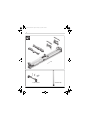
Please also observe the representation of the delivery scope at the
beginning of the operating instructions.
Before assembling the saw stand, check if all
parts listed below are provided:
No.
Designation
Quantity
Saw stand GTA 3800
1
4
Attachment set
2
1
Workpiece support
2
7
Roller stand
2
14
Socket spanner/Allen key/
Phillips screwdriver
1
19
Power tool fastening kit
consisting of:
– Hexagon bolt
(M8 x 45)
– Washer
4
4
Additionally required tools (not in delivery
scope):
– Open-end spanner (10 mm)
Assembling the Saw Stand
– Carefully remove all parts included in the delivery from their packaging.
– Remove all packaging material.
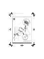
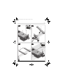
Setting Up the Saw Stand (see figures A1 – A2)
– Lay the saw stand upside down on the floor
(legs facing upward).
– Push the locking pin 15 in and tilt the leg upward until the locking pin can be heard to engage.
– Repeat this workstep with the other three
legs.
– Turn around the saw stand to the working
position.
– Ensure that the saw stand is stable and that
all locking pins have engaged.
Bosch Power Tools
– Screw the leg in or out until the saw stand is
aligned level and all four legs face against the
floor.
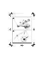
Mounting the Roller Stand (see figure B1)
– Unscrew the Phillips screw of the roller
stand 7 with the Phillips screwdriver 14 provided.
If required, counter-hold the lock nut on the
other side of the roller stand using a spanner
(size 10 mm).
– Disassemble the roller stand 7.
There are different possibilities to arrange the
individual rollers to the workpiece support with
the internally-threaded rod (see figure).
– Arrange the individual parts as required and
slide the internally-threaded rod through the
rollers and the workpiece support 1.
– Screw all parts together again.
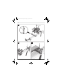
Mounting the Workpiece Support
(see figure B2)
– Loosen the locking knobs 3 and pull the table
extensions 2 via both sides of the saw stand
lightly outward.
– Slide the workpiece supports 1 from the left
and right each into the upper groove of the
saw stand or the table extension.
The length stops 8 must face outward.
– Tighten the locking knob 6 to lock the workpiece support.
Preparing the Saw Stand
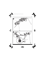
Preparing the Attachment Sets
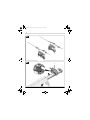
(see figures C1 – C4)
– To release the attachment sets 4, press buttons 16 each and open the levers 17.
– Measure the distance x between the mounting holes and your power tool.
– Position the attachment sets 4 centred on
the saw stand and at the matching clearance
x to each other.
– Lock the levers 17 again. The attachment
sets are now firmly positioned on the saw
stand.
1 609 929 U17 | (4/8/10)