1
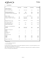
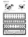
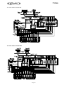
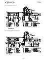
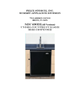
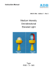
C
Triton
Please keep these operating instructions in a safe place.
Dear Customer:
Check this product for visible damage immediately upon receipt. Inform the shipper if there is any shipping damage.
Note that damage resulting from improper handling or operation is not covered under the warranty.
Before putting the device into operation:
Read all the operating instructions carefully.
Familiarize yourself with all controls.
Ask the service company installing the device to write its address down here for any subsequent repairs, emergencies,
etc.
Address of your technical service company:
Name:
................................
City:
................................
Street address:
................................
Telephone:
................................
Contact person:
................................
Table of Contents
1.
2.
3.
4.
5.
6.
7.
8.
9.
10.
11.
12.
1.
Page
Introduction ...................................................................................... 15
Safety Regulations ............................................................................ 16
Installation Site Requirements .......................................................... 16
Installation ........................................................................................ 17
Putting into and out of Service ......................................................... 18
Instructions for Cleaning .................................................................. 19
Problems and Troubleshooting ......................................................... 20
Technical Data .................................................................................. 21
Illustration ........................................................................................ 22
Flow Chart and Circuit Diagram ..................................................... 23
Adjusting of the ice-bank-probe ........................................................ 25
Installation Check List ...................................................................... 26
Introduction
Our foremost aim is to produce a quality product. If you should encounter any difficulty which these operating
instructions do not help you with, call or write us. We will be glad to be of assistance. If you write, please include the
model and serial number of the device.
Our address:
IMI Cornelius Deutschland GmbH
Carl-Leverkus-Strasse 15
D-40764 Langenfeld, Germany
Tel. 0(xx49) 2173 793-0
Fax: 0(2173) 2173 77438
Page 15
C
2.
Safety Regulations
2.1
General Safety Regulations
Triton
This device is of leading-edge design and manufacture. If used and maintained in accordance with these operating
instructions, it will be safe to operate. Please comply with the following safety instructions to avoid hazards and
damage.
The device must be in satisfactory condition whenever operated. Any modifications which detrimentally affect the
safety of the device are therefore strictly prohibited. Please contact your service company if you wish to obtain more
information about safety.
No safety equipment (such as safety valves, overload protection devices, etc.) is to be removed, modified or put out of
commission (risk of injury or death!).
Take care that only authorized persons work on the device and that the operators are trained. Make certain that no
unauthorized persons change the settings on the device or tamper with it.
You are obligated to check the device on a daily basis for externally discernible damage and defects. Immediately
report modifications which affect safety and function to the service company nearest you.
Note that only original CORNELIUS replacement parts and accessories which have been checked and approved are
to be used. IMI Cornelius Deutschland GmbH assumes no liability whatsoever for damage resulting from the use of
non-original parts and accessories or from improper handling.
2.2
Safety Instructions Electricity
An electric shock may be fatal or result in serious injury. For this reason, any unauthorized tampering is strictly
prohibited. Water and electricity are a fatal mixture.
Always pull out the mains plug before any cleaning work on or near the device. As delivered, it features a moulded
earthing-pin plug and it must be connected to a socket outlet with an earthing contact. If no appropriate socket outlet
with an earthing contact is available, the connection must be made by authorized persons only, with the regulations
applicable at the installation site (VDE standards in Germany, for example) being observed.
2.3
Safety Instructions CO2
Place the carbon dioxide cylinder in an upright position next to the workstation and secure it against falling over.
Protect it against heat (e.g., against sunshine). Minimum distance from heater 0.5 m (TRSK).
Escaping carbon dioxide is heavier than air and may present danger of suffocation if large quantities collect in
enclosed spaces. Remember that parts of the device are at operating pressure. Do not loosen or dismantle any
components at operating pressure.
3.
Installation Requirements
3.1
Installation Sites
Comply with the valid national regulations for installation sites and electrical connections. Ventilation of the
installation sites must be appropriate for device output. Inadequate ventilation of the device will result in its
overheating and being destroyed. Always make certain that no intake or discharge vents are covered.
Heat output in watts
Air flow in m3/hour
1)
2/3 HP Version
Triton 150
1100
400
Triton 350
1600 / 1700 1)
400
Page 16
Triton 700
2000
500
Triton 2500
3000
700
C
3.2
Triton
Electrical Connections
A socket outlet with an earthing contact featuring a maximum protection of 16 amps is required.
The line voltage must always be within following tolerances: 230 VAC +6%/-10% / 50 Hz
Power consumption in watts
1)
2/3 HP Version
4.
Triton 150
540
Triton 350
920 / 1000 1)
Triton 700
1150
Triton 2500
1550
Installation
The device must be installed by a trained service technician.
Please take care, that the socket for the unit is always accessible.
There is no user serviceable items inside the equipment.
If the power supply cable to the unit is damaged, it has to be replaced by the manufacturer, the service partner or any
other qualified person to avoid safety hazard.
4.1
Water Connection
Connecting only to drinkable water
Connect the device to a feed line with an inner diameter of 10 mm. We recommend using a water filter and a water
pressure regulator for the water input. To permit flushing of the filter, a T-piece should be mounted downstream of the
water pressure regulator. The water flow pressure should be 3 bar (mount control pressure gauge on water pressure
regulator). A flow rate of 560 litres / hour is required. Due to the high flow rate, it may be necessary to install several
water filters and water tubes in parallel.
4.2
CO2 Connection
You will require a two-wire pressure regulator, 7 bar. Using tubing with an inner diameter of 4 mm, connect the
pressure regulator to the carbonator. Set the CO2-pressure to 3,5 to 4,5 bar.
The unit include a CO2-pressure switch to switch off the dispensing valves at a CO2-pressure less than 3 bar.
4.3
Connecting Soda Water and Still Water Premix/Postmix Syrup
Connect one tube with an inner diameter of 6 mm to each device connection. Connect the tube end to the correct
cooling coil inputs of the cooler circuit carbonator.
4.4
Connection of Still Water Control
For still water, one switching cable (1 x 0.75 mm2) per still water tap must run from the soda circuit carbonator to the
still water tap. The electronic control system is actuated via this cable. An addition cable from one of the still water
valves is necessery.
Alternativley, there are some units which are controlled by a pressure switch for the still water. It is recommended to
adjust the still water flow pressure to 3.2 bar and the switching point of the pressure switch to 4.2 bar. If a different
flow pressure is required the switching point of the pressure switch must be set 1 bar above the flow pressure.
Refer to the circuit diagram for the connection. The flow rate of the still water should be 170 ml in 4 to 5 seconds.
5.
Putting into and out of Service
5.1
Putting into Service
Comply with the cleaning regulations defined by law before beginning each operation.
Page 17
C
Triton
Clean the couplings on the container for beverage / syrup every time before you attach them. Connect coupling to
container for beverage / syrup. Note: Gray = CO2, black = beverage / syrup.
Open the cylinder globe valve on the CO2-cylinder and the globe valve on the pressure regulator. Check the CO2pressure at the pressure regulator. It should be within the following standard values:
Syrup:
3.5 to
CO2 carbonization pressure: 3.5 to
Light product:
0.5 to
Drinking water:
4.0 to
4.0
4.5
1.0
4.5
bar
bar
bar
bar
Set the CO2-pressure by turning the control screw:
Clockwise to increase the pressure
Counter-clockwise to reduce the pressure
Afterwards check the CO2-lines for leaks by closing the CO2-globe valve. The admission pressure displayed at the
pressure regulator should not drop. If it does, notify the service technician immediately. Do not forget to re-open the
CO2-globe valve after the check.
Open the water feed line and check the flow pressure in it. Standard value: 2.0 to 3.0 bar. Set it at the control screw
on the water pressure regulator:
Clockwise to increase the pressure
Counter-clockwise to reduce the pressure
Check the beverage / syrup lines for leaks. Only a visual inspection is possible. If liquid is leaking, call a service
technician.
Close the water feed line. The pressure displayed should not drop. If it does, notify the service technician immediately.
Afterwards, re-open the water feed line.
5.2
Turning On the Device
The water bath must be filled to overflowing with tap water. Refer to the technical data for the amount required. To
prevent algae from forming in the water, add the disinfectant Molco (PN 14-9670-150). The 150 ml container of
disinfectant is sufficient for 30 liters of water.
Insert the mains plug for the cooler into the socket outlet with an earthing contact.
Ice bank controlled units start working after the water bath fills with water and switch off automatically after the ice
bank is built up. The control board of the unit has a time delay for switching on and off the cooling sytem, when it runs
in ice bank mode. After the cooling system is switched on the running time is not less then 5 minutes. Switch off signals
will be ignored during this time. After the cooling system is switched off the break time is not less then 3 minutes.
Switch on signals will be ignored during this time. The break time of 3 minutes is valid for turning on the device and
after a break down of the power supply.
This unit contains a 3-pin icebank probe. Take care that the probe is always correctly adjusted. Wrongly adjusted
probes can be adjusted by using the adjusting device 22-0055-X99.
The agitator motor is a closed version. Temperatures up to 80°C are normal.
The carbonator pump switches on automatically and fills the carbonator container. The carbonator pump switches off
when the water has reached its highest level in the carbonator container but after no more than 20 minutes. Long run
periods are signs of leaks or insufficient water. It is then only possible to turn the pump back on by executing a
network reset (pulling out the mains plug briefly).
Release air from the carbonator container by pulling the safety valve for about 2 to 4 seconds. The circulation pump
has to be switch on manual by using the switch at the leval control board (not Triton 150).
5.3
End of Operation
It is imperative that the CO2 cylinder and water line be turned off each time operation is ended.
Page 18
C
5.4
Triton
Daily Inspection
Check whether carbon dioxide and water lines are open. Working with closed water feed lines results in draining of
the python and the carbonator container. The air must then be carefully bled from the python by opening the soda
water tap, as the circulation pump will not move the water otherwise.
Check the beverage / syrup lines for leaks. Only a visual inspection is possible. If liquid escapes, call a service
technician.
Check the CO2 lines for leaks by closing valve on the CO2 cylinder. The inlet pressure indicated on the pressure
regulator should not drop. If it does, call a service technician immediately. Do not forget to re-open the CO2 cylinder
valve afterwards.
5.5
Putting out of Service
Perform the following steps in case of protracted standstill periods:
Close the CO2-cylinder, the CO2-stopcocks on pressure regulators and the water feed line.
Pull the mains plug out of socket outlet with earthing contact.
Detach the couplings from beverage containers.
Have the device cleaned and emptied.
Only trained specialists are carry out this procedure.
6.
Instructions for Cleaning
Comply with the national regulations for cleaning bar equipment which are valid at the particular installation site.
Clean connection parts and tap fittings in advance whenever making connections or changing the type of beverage.
Clean parts coming into contact with air and beverage, the mouth of the tap for example, on a daily basis.
The risk of serious etching exists when handling liquid cleaners. Always wear safety glasses and appropriate clothing
during cleaning jobs. Follow the instructions of the cleaner manufacturer.
The liquefier louvres must be cleaned at regular intervals which vary according to the amount of contamination at the
erection site (approximately every three months). This is best done with a brush and a vacuum cleaner.
The level of the water bath must be checked regularly and the contents must be exchanged at least once annually.
Algae formation can be reduced by adding disinfectant.
The device is to be cleaned and emptied by trained specialists only on the basis of the following recommendations:
To be cleaned by
trained personnel
Before commissioning
Before each change
of type of beverage
Before and after a
pause
Every 2 weeks
Every 3 months
Every 12 months
CO2lines
Beverage
lines
Syrup
lines
X
X
X
X
X
X
Soda water
lines
X
X
X
X
Page 19
X
C
7.
Triton
Problems and Troubleshooting
Before looking for problems with the dispensing equipment, first check:
Is the flow of electricity to the device interrupted?
Is the flow of water to the device interrupted?
Are the beverage containers empty?
Is the CO2-cylinder empty?
Type of problem
Cause
Remedy
Beverage too warm,
compressor running
Condenser dirty
or covered.
Too much beverage
being removed
Compressor not
turned on.
Syrup stored too long
and enriched with CO2
CO2-pressure too high
All syrups
enriched with CO2
All beverages too
warm
Carbonator pump is
not running
Use brush to clean condenser between louvres.
Note out-put capacity
Beverage too warm,
compressor not running
Beverage foams at a tap
Beverage foams at all taps
Tap just outputs
concentrate
CO2-volume in the
beverage is too low
Too much or not enough
syrup in the beverage
Air in carbonator
Too much beverage
being removed
CO2-cylinder empty
Globe valve on CO2cylinder closed
Stopcock on pressure
regulator closed
CO2-pressure too low
Water temperature
too high
Regulator in tap
is clamping
Delivery pressure for
syrup too
low or too high
Page 20
Turn compressor on, otherwise
call service technician
Connect container
with fresh basic material
Set pressure
Connect container
with fresh basic materials.
Check storage temp
See “Beverage too warm ...”
Check if water feed line
is open
Check water flow pressure
of 3bar
Check whether the carbonator
motor is running; if
not, call service technician
Bleed air
Watch output
capacity
Change CO2-cyl.
Open globe valve
Open stopcock
Adjust pressure
Adjust to lower
temperature
Call service
technician
Adjust CO2 pressure
C
8.
Triton
Technical Datas
Triton 150
Triton 700
Triton 2500
670
2500
30
2400
220
55
4400
240
540
400
230 V / 50 Hz
920 / 1000 1)
1150
500 / 680 1)
790
1550
1370
(1/3)
(1/2) / (2/3)
0,240
0,350 / 330
130
340 / 500
Weight of ice bank in kg
Ice bank performance in kcal
Ice build up in minutes without python
9
720
110
18
1440
160 / 145
Supply voltage
Power consumption in watts
Compressor output in watts (hp)
Refrigerant R134 a in kg
Carbonator pump output
in L / hour at 10 bar
Circulation pump output
in liters / hour at 2 bar
1)
1)
1)
1)
(3/4)
(1)
0,410
0,800
280
280
280
2x280
240
320
320
320
767
660
1163
1000
1
6
1
1
1
8
1
1
1
10
1
1
1
Dimensions in mm
Height
Width
Depth
580
385
585
595
780
433
640
840
490
710
1040
600
Shipping weight in kg
50
85
95
105
Cooling / ice bank performance
in watts
in Kcal
Number of cooling coils
Syrup
Premix
Drinking water
Still water
1)
Triton 350
Output capacity at a
tap rate of 4 drinks
of 0.3 L each per minute
483
415
659 / 675
567 / 580
5
1
1)
1)
2/3 HP Version
* at -10°C evaporation temperature
** with 10 m SC python
Cooling capacities and output capacity at 24°C ambient temperatures and water or syrup inlet temperatures of 24°C
and beverage outlet temperatures of less than 5°C.
When Cornelius pythons are used, a cooling loss of 13 kcal/hour per running meter must be included in calculations.
We reserve the right to make modifications.
Page 21
C
9.
Triton
Illustration of the Triton
Triton 350, Triton 700 Triton 2500 (for example Triton 350)
9.1
Connections at the unit
9.1.1 Triton 150
9.1.2 Triton 350
9.1.3 Triton 700
9.1.4 Triton 2500
Page 22
Triton 150
C
10.
Triton
Flow Chart and Circuit diagram
10.1 Flow Chart of Triton 150
10.2 Flow Chart of Triton 350
Page 23
C
Triton
10.3 Flow Chart of Triton 700
10.4 Flow Chart of Triton 2500
Page 24
C
Triton
10.5 Circuit diagram of Triton 150
10.6 Circuit diagram of Triton 350 and 700
Page 25
C
Triton
10.7 Circuit diagram of Triton 2500
11.
Adjusting of the ice-bank-probe
The dimension is critical for the adjustment.
The icebank probe adjustment tool is avaible under PN 22-0055-XXX
Page 26
C
12.
Triton
Installation Check List
You can use this check list to review the installation of the device. Fill out the check list and keep it with the operating
instructions.
Part number of the device:
__________________
Serial number of the device:
__________________
Installation site:
__________________
Installation date:
__________________
Installed by:
__________________
Settings:
Water flow pressure:
Target
Actual
2 bar
____ bar
CO2 pressure:
3.5 to 4.5 bar
____ bar
CO2 volume at 4°C:
4.0% by vol.
____ % by vol
Carbonator filling time:
about 8 sec
____ sec
3 bar
____ bar
Stillwater pressure switch
3.2 bar
____ bar
pressure switch stillwatercontrol
4.2 bar
____ bar
CO2-pressure switch
Page 27