1
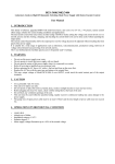
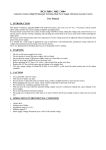
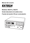
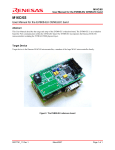
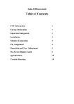
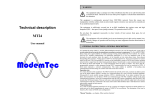
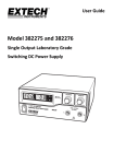
User's Guide
Model 382275 and 382276
Single Output Laboratory Grade
Switching DC Power Supply
Introduction
Congratulations on your purchase of the Extech 382275 Single Output Laboratory Grade
DC Power Supply.
The dual action (coarse/fine tune) rotary encoder makes setting the voltage and current
levels ever so smooth, precise and fast. Setting, changing, and checking the current limit
level can be done easily without sparking the output poles.
The remote control functionality allows the output power on/off, voltage & current to be
adjusted without touching the front panel of the power supply.
It is suitable for a wide range of applications including laboratory, telecommunication,
production testing, field test of voltage critical distant load, powering of dc network etc.,
The three user defined presets facilitate quick access to frequently used voltage and
current settings.
This power supply is shipped fully tested and calibrated and, with proper use, will provide
years of reliable service.
Safety
WARNING
• Do not use this power supply near water.
• Do not operate or touch this power supply with wet hands.
• Do not open the casing of the power supply when it is connected to AC power.
• Refer all servicing to qualified service personnel only.
• Before replacing the fuse, identify and fix any problems.
• Replace the AC fuse with the same type and rating as the original fuse.
CAUTION
• Use a grounded 3 pin AC source.
• This unit is for indoor use only.
• Do not operate or place this unit in direct sunlight or in a humid or dusty location.
• Do not place near any heat source.
• Before plugging into local AC mains, check the rating label at the back of the unit.
• Do not block the ventilation openings of the unit.
• This unit must be used within the specified rating, regular excessive continuous
loading may cause damage to the power supply.
• The gauge size of the input power cable must be at least 3 “(0.75mm) and the total
length of power cable must not exceed 118” (3m)
2
382275/6 V1.0 08/09
Power Supply Description
2
3
1
4
5
6
10
9
7
8
1.
Power Switch ON/OFF
2.
Voltage Display
3.
Current Display
4.
Constant Voltage Indicator LED
5.
Rear Control Indicator LED (Switches On when in Preset, Remote Control or Set
Mode)
6.
Output Voltage Control Knob (Controls both the main and auxiliary output voltage)
7.
Output Current Control Knob (Controls both the main and auxiliary output current)
8.
Positive Auxiliary Output Terminal (Max 5 Amps)
9.
Negative Auxiliary Output Terminal (Max 5 Amps)
10. Constant Current Indicator LED
3
382275/6 V1.0 08/09
Rear Panel Description
3
2
1
6
1.
4
5
Main Output (Max 20 Amps)
2.
P1, P2 and P3 Recall Switch
3.
Cooling Fan for Ventilation
4.
AC input Plug and Fuse
5.
Remote Control Connector
6.
Mode Switch
4
382275/6 V1.0 08/09
Mode Descriptions
Control Mode Selection
There are four modes: Normal, Preset, Set and Remote Control mode for the power
supply. Slide the Mode Selection Switch to the desired Mode. The power supply
defaults to the Normal Mode with maximum current level CC.
Normal Mode
Normal Mode is the factory preset mode. The power supply’s output voltage and current
are controlled by the dual action volume knobs. Push the knobs to toggle the coarse
and fine tuning; notice the subtle changes in brightness of related LED. Adjust the knobs
to the desired values by trying coarse and fine tuning. Turn the Current Knob lightly in
any direction to check the preset current level. The display will resume its normal
brightness after a few seconds to confirm the adjustment.
Preset Mode
In this mode, the Rear Control Light is on to indicate panel voltage and the current
controls are de-activated.
There are three preset outputs, P1, P2 and P3. These are selectable by using the
Recall Switch located on the rear of the power supply.
The preset values are factory set as shown in the following table. The output rating is
adjustable.
Presets.
Output Voltage
Output Current
P1
5V
Maximum
P2
13.8V
Maximum
P3
25V
Maximum
Set Mode
In this mode the voltage and current remote control can be used at the same time or
separately.
1.
Set the Mode Switch located on the rear of the power supply to the “Set” position.
2.
To define the preset output set the Recall Switch to the P1, P2 or P3 position.
3.
Use the front panel Voltage Control Knob to set the desired voltage value.
4.
Use the front panel Current Control Knob to set the desired current value.
5.
Repeat the procedure for the remaining presets: P1, P2 or P3 if desired.
6.
Move the Recall Switch from the Set to the Preset position to confirm settings.
5
382275/6 V1.0 08/09
Power Up Checks
1.
First, check the rating label of the power supply and make sure it complies with the
AC mains voltage. Next, set the Mode Switch located on the rear of the power
supply to the Normal Position.
2.
Listen for the cooling fan when switching on the power supply. The power supply
performs a series of self test checks on startup which include testing the cooling
fan. The fan will stop completely after a few seconds after running at high speed
indicating that it is in good order. The CV, V and A LEDs switch on displaying
voltage and 0.0 current. To check the current level, turn the control knob one click
in either direction to view the current value. The current display returns to 0.0 after
a few seconds.
Operation
Using the Control Knobs
The rotary encoder control knobs offer fine/coarse tuning with clicking movement.
1.
Push the knobs to toggle between coarse and fine tuning, notice the subtle
changes in brightness of the related LED.
2.
Adjust the knobs to the desired values by using coarse and then fine tuning. The
display will resume its normal brightness after a few seconds to confirm the
adjustment.
Connecting to UUT (Unit Under Test)
1. Connect the equipment to the power supply. Red (+) is connected to the positive
polarity input of the UUT and Black (-) is connected to the negative polarity input of
the UUT.
2.
Switch on the power supply first; the panel meter & green CV Indicator should
switch on again.
3.
Switch on the UUT; the panel meter & green CV Indicator should remain on.
4.
The UUT is now ready. When operation is completed, switch off the UUT and
then the power supply.
5.
When disconnecting the power supply from the UUT, disconnect the remote
sensing wire first and then disconnect the output cables.
6
382275/6 V1.0 08/09
Remote Control (Voltage)
1.
Remove the black portion of the remote control
connector plug by removing the screw as shown.
2.
Solder 3 wires (22AWG) to PORT 1, 2 & 4 of the
1
2
7
8
3
black portion as shown.
4
3.
Ensure that the load is disconnected and the power supply is OFF.
4.
Plug the remote connector plug into the remote control terminal of the power
supply.
5.
Secure the remote connector plug to the terminal socket by locking the connector
ring.
6
5
NOTE: Choose either method A or B as explained below to use the remote control
feature.
Method A : Using A Voltage Source
A variable external voltage source of 0 ~ 5V is fed into the remote control terminal to
adjust the output voltage level.
Warning!: Do not input voltages higher than 5V, otherwise the Over Voltage
Protection (OVP) will be triggered.
1.
Ensure that the load is disconnected and that the power supply is OFF.
2.
Use ONLY wires from Port 2 (Positive) and Port 4 (Negative)
3.
Switch on the power supply.
4.
Vary the external input voltage 0~5V to check and verify the full output voltage
range of the supply.
5.
Switch OFF the power supply.
7
382275/6 V1.0 08/09
Method B : Using A 5Kohm Variable Resistor
1.
Ensure that the load is disconnected and that the power supply is OFF.
2.
Prepare a 5Kohm variable resistor and use the wires from Port 1, 2 and 4 as
shown below:
2
1
4
5KΩ
3.
Switch the power supply ON.
4.
Adjust the 5Kohm variable resistor from one end to other end to check and verify
the full output voltage range of the power supply.
5.
Switch OFF the power supply.
Remote Control (Current)
1.
Using the same connector plug referred to in
the voltage remote control section, remove
the black portion of the remote control
connector plug by removing the screw as
shown.
2.
Solder 3 wires (22AWG) to PORT 1, 3 & 4 of
the black portion as shown:
1
2
7
8
3
4
6
5
3.
Ensure that the load is disconnected and that the power supply is OFF.
4.
Plug the remote connector into the remote control terminal of the power supply.
5.
Secure the remote connector plug to the terminal socket using the locking
connector ring.
8
382275/6 V1.0 08/09
Method A : Using A Voltage Source
A variable external voltage source of 0 ~ 5V is fed into the remote control terminal to
adjust the output current level.
Warning!: Do not input voltages higher than 5V, otherwise the Over Voltage
Protection (OVP) will be triggered.
1.
Ensure that the load is disconnected and the power supply is OFF.
2.
Use ONLY wires from port 3 (Positive) and 4 (Negative)
3.
Switch on the power supply.
4.
Vary the external input voltage 0~5V to check and verify for the full output current
range of the supply.
5.
Switch OFF the power supply.
Method B : Using 5Kohm Variable Resistor
1.
Ensure that the load is disconnected and that the power supply is OFF.
2.
Prepare a 5Kohm variable resistor and use wires from Port 1, 3 and 4 as shown.
3
1
4
5KΩ
3.
Switch the power supply ON.
4.
Adjust the 5Kohm variable resistor from one end to other end to check and verify
the full output current range of the power supply.
5.
Switch OFF the power supply.
Enabling and Disabling the Output
Use Port 4 and 5 to remotely control the OUTPUT ON/OFF.
1.
Open Port 4 and 5 to ENABLE the output (by default)
2.
Short Port 4 and 5 to DISABLE the output..
9
382275/6 V1.0 08/09
Faults and Troubleshooting
OUP: Over Voltage Protection
oup
C.V.
A
C.C.
This unit has a built-in tracking over voltage protection feature. In the event of
output voltage becoming greater than the set value (see specified range from
specifications table), protection will be triggered and the output power will be cut off.
(OUP warning appears)
To reset the warning, power off the unit and remove all loading. Power the unit back
on again to resume normal operation. If this problem persists, please contact
Extech Technical Support.
OTP: Over Temperature Protection
C.V.
A
C.C.
There is a thermo sensor inside of the unit to monitor and to prevent the unit from
overheating. The OTP warning will appear on the display and the output will switch
off. When this warning appears, switch off the unit and remove all loading.
Check the load and output setting. Allow the unit to cool for at least 30 minutes.
Check if the ventilation is blocked; check for clearance around the power supply.
Listen carefully for the short wind noise from the cooling fan when the unit is
powered up again.
If the fan is not heard upon power up, it may be faulty; please contact Extech
Technical Support.
OLP: Over Load Protection
C.V.
A
C.C.
Normally the overload protection is sustained by the CC constant current mode.
However, if the CC mode fails it may cause serious damage to the test piece or
load . OLP is used to minimize the extent of damage to the loads. Switch off the
power supply as soon as the warning appears.
To reset this warning, switch off the unit and remove all loading. Switch the unit
back on again and recheck with caution .
If this problem persists, please contact Extech Technical Support.
10
382275/6 V1.0 08/09
Specifications
Output
Voltage
Regulation
Current
Regulation
Meter
Accuracy
Tracking
Over Voltage
Protection
Variable Output Voltage
1 to 30VDC
Variable Output Current
1 to 20A
Load (10 to 100% Load)
50mV
Line (170 to 264VAC Variation)
20mV
Load (90 to 10% Rated Voltage)
100mA
Line (170 to 264VAC Variation)
50mA
Ripple & Noise (peak-peak) Voltage
50mV
Current Ripple & Noise (r.m.s.)
30mA
Voltage Meter
±(0.2% +3 digits)
Current Meter
±(0.2% +3 digits)
1 to 5V
Default Value is +2V
5 to 20V
Default Value is+3V
20 to 30V
Input Voltage
Rated Load Input Current
Efficiency
Switching Frequency
Cooling Method
Protections
Special Features
Operating Humidity Range
Altitude
Pollution Degree
Main Supply Voltage Fluctuation
Dimensions (WxHxD)
Weight
Default Value is +4V
100 to 120VAC 50/60Hz (382275)
210 to 230VAC 50/60Hz (382276)
6.3A
86.5% at optimal load
75 to 95Khz
Thermostatic Control Fan from Zero to full speed
Overload, Short Circuit by Constant Current,
Output Tracking Over Voltage, Over
Temperature
Three User defined VI presets, Remote control V, I
and output on-off
10 to 80%RH
7000 Feet (2000 meters)
2
±10% of the nominal voltage
7.9 x 3.5 x 8.5“ ( 200 x 90 x 215 mm)
5.7 lbs (2.6 kg)
11
382275/6 V1.0 08/09
Maintenance and Repair Services
Cleaning the meter housing
Prior to cleaning the meter housing, disconnect the mains plug from the power outlet.
Clean only with a damp, soft cloth and a commercially available mild household cleaner.
Ensure that no water gets inside the equipment to prevent possible shorts and damage to
the equipment.
Calibration and Repair Services
Extech offers repair and calibration services for the products we sell. Extech also
provides NIST certification for most products. Call the Customer Care Department for
information on calibration services available for this product. Extech recommends that
annual calibrations be performed to verify meter performance and accuracy.
12
382275/6 V1.0 08/09
Warranty
EXTECH INSTRUMENTS CORPORATION (A FLIR COMPANY) warrants this instrument to
be free of defects in parts and workmanship for one year from date of shipment (a six
month limited warranty applies to sensors and cables). If it should become necessary to
return the instrument for service during or beyond the warranty period, contact the
Customer Service Department at (781) 890-7440 ext. 210 for authorization or visit our
website www.extech.com for contact information. A Return Authorization (RA) number
must be issued before any product is returned to Extech. The sender is responsible for
shipping charges, freight, insurance and proper packaging to prevent damage in transit.
This warranty does not apply to defects resulting from action of the user such as misuse,
improper wiring, operation outside of specification, improper maintenance or repair, or
unauthorized modification. Extech specifically disclaims any implied warranties or
merchantability or fitness for a specific purpose and will not be liable for any direct, indirect,
incidental or consequential damages. Extech's total liability is limited to repair or
replacement of the product. The warranty set forth above is inclusive and no other
warranty, whether written or oral, is expressed or implied.
Support line (781) 890-7440
Technical Support: Extension 200; E-mail: [email protected]
Repair & Returns: Extension 210; E-mail: [email protected]
Product specifications subject to change without notice
For the latest version of this User Guide, Software updates, and other
up-to-the-minute product information, visit our website: www.extech.com
Extech Instruments Corporation, 285 Bear Hill Road, Waltham, MA 02451
Copyright © 2009 Extech Instruments Corporation (a FLIR company)
All rights reserved including the right of reproduction in whole or in part in any form.
13
382275/6 V1.0 08/09
14
382275/6 V1.0 08/09