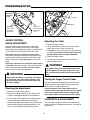
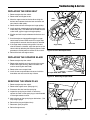
1
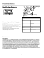
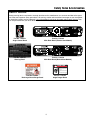
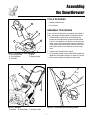
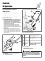
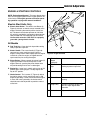
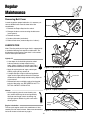
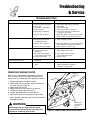
OPERATOR’S
MANUAL
Single Stage
Snowthrower
520M Models
Mfg. No.
1694585
7085663
Description
5201M, 5HP Snowthrower, Manual Start
SS5201R, 5HP Snowthrower, Manual Start
520E Models
Mfg. No.
1694586
7085664
Description
5201E, 5HP Snowthrower, Electric Start
SS5201E, 5HP Snowthrower, Electric Start
Manual No 7100951
I.R. 6/21/2006
TP 100-5201-00-SX-SN
Table of Contents
Regular Maintenance
Removing Belt Cover ............................................14
Lubrication ............................................................14
Troubleshooting & Service
Troubleshooting ....................................................15
Removing Engine Cover .......................................15
Auger Control Cable Adjustment ..........................16
Carburetor Adjustment (Ref. only) ........................16
Replacing the Drive Belt .......................................17
Replacing the Scraper Blade ................................17
Servicing the Spark Plug.......................................17
Appendices
Specifications ........................................................18
Parts & Accessories ..............................................18
Technical Manuals ................................................18
Safety Rules & Information
Training ...................................................................2
Preparation .............................................................2
Operation ................................................................2
Children...................................................................3
Clearing a Clogged Discharge Chute .....................3
Service, Maintenance, and Storage ........................3
Emissions................................................................3
Identification Numbers ............................................4
Safety Decals ..........................................................5
International Symbols .............................................6
Assembling the Snowthrower ....................................7
Controls & Operation
Snowthrower Controls.............................................8
Engine & Starting Controls......................................9
General Operation ................................................10
Checks Before Each Start-Up ...............................10
Mixing Fuel............................................................11
Starting the Engine ...............................................12
Stopping the Engine..............................................12
Operating the Snowthrower ..................................13
Snowthrowing Tips................................................13
After Each Use ......................................................13
Off-Season Storage ..............................................13
Starting After Storage ...........................................11
WARNING
Engine exhaust from this product contains
chemicals known, in certain quantities, to cause
cancer, birth defects, or other reproductive harm.
1
Safety Rules & Information
This machine is capable to amputating hands and feet and throwing objects. Read these safety rules and
follow them closely. Failure to obey these rules could result in loss of control of unit, severe personal injury
or death to you, or bystanders, or damage to property or equipment. The triangle
in text signifies
important cautions or warnings which must be followed.
TRAINING
OPERATION
1. Read, understand, and follow all instructions on the
machine and in the manuals before operating this
unit. Be thoroughly familiar with the controls and the
proper use of the equipment. Know how to stop the
unit and disengage the controls quickly.
2. Never allow children to operate the equipment.
Never allow adults to operate the equipment without
proper instruction.
3. Keep the area of operation clear of all persons, particularly small children and pets.
4. Exercise caution to avoid slipping or falling especially
when operating in reverse.
1. Do not put hands or feet near or under rotating parts.
Keep clear of the discharge opening at all times.
2. Exercise extreme caution when operating on or
crossing gravel drives, walks, or roads. Stay alert for
hidden hazards or traffic.
3. After striking a foreign object, stop the engine (motor),
remove the wire from the spark plug, disconnect the
cord on electric motors, thoroughly inspect the
snowthrower for any damage, and repair the damage
before restarting and operating the snowthrower.
4. If the unit should start to vibrate abnormally, stop the
engine (motor) and check immediately for the cause.
Vibration is generally a warning of trouble.
5. Stop the engine (motor) whenever you leave the
operating position, before unclogging the
collector/impeller housing or discharge guide, and
when making any repairs, adjustments, or inspections.
6. When cleaning, repairing, or inspecting make certain
the collector/impeller and all moving parts have
stopped. Disconnect the spark plug wire and keep
the wire away from the plug to prevent accidental
starting.
7. Do not run the engine indoors except for starting the
engine or for transporting the snowthrower in or out of
the building. Open the outside doors; exhaust fumes
are dangerous.
8. Exercise extreme caution when operating on slopes.
Do not attempt to clear steep slopes.
9. Never operate the snowthrower without proper
guards plates, or other safety protective devices in
place and working.
10. Never direct the discharge toward people or areas
where property damage can occur. Keep children
and others away.
11. Do not overload the machine capacity by attempting
to clear snow at too fast a rate.
12. Never operate the machine at high transport speeds
on slippery surfaces. Look behind and use care
when operating in reverse.
13. Disengage power to the collector/impeller when
snowthrower is transported or not in use.
14. Use only attachments and accessories approved by
the manufacturer of the snowthrower (such as wheel
weights, counterweights, or cabs).
15. Never operate the snowthrower without good visibility
or light. Always be sure of your footing, and keep a
firm hold on the handles. Walk, never run.
16. Never touch a hot engine or muffler.
17. Never operate the snowthrower near glass enclosures, automobiles, window wells, drop-offs, and the
like without proper adjustment of the discharge angle.
18. Never direct discharge at bystanders or allow anyone
in front of the unit.
19. Never leave a running unit unattended. Always disengage the auger and traction controls, stop engine,
and remove keys.
20. Do not operate the unit while under the influence of
alcohol or drugs.
PREPARATION
1. Thoroughly inspect the area where the equipment is
to be used and remove all doormat, sleds, boards,
wires, and other foreign objects.
2. Disengage all clutches and shift into neutral before
starting engine (motor).
3. Do not operate the equipment without wearing adequate winter outer garments. Wear footwear that will
improve footing on slippery surfaces. Avoid loose fitting clothing that can get caught in moving parts.
4. Handle fuel with care; it is highly flammable.
(a) Use an approved fuel container.
(b) Never add fuel to a running engine or hot engine.
(c) Fill fuel tank outdoors with extreme care. Never fill
fuel tank indoors. Replace fuel cap securely and
wipe up spilled fuel.
(d) Never fill containers inside a vehicle or on a truck
or trailer bed with a plastic liner. Always place containers on the ground, away from your vehicle, before
filling.
(e) When practical, remove gas-powered equipment
from the truck or trailer and refuel it on the ground. If
this is not possible, then refuel such on a trailer with a
portable container, rather than from a gasoline dispenser nozzle.
(f) Keep nozzle in contact with the rim of the fuel tank
or container opening at all times, until refueling is
complete. Do not use a nozzle lock-open device.
(g) Replace gasoline cap securely and wipe up spilled
fuel.
(h) If fuel is spilled on clothing, change clothing immediately.
5. Use extension cords and receptacles as specified by
the manufacturer for all units with electric drive
motors or electric starting motors.
6. Adjust the collector housing height to clear gravel or
crushed rock surfaces.
7. Never attempt to make any adjustments while the
engine (motor) is running (except when specifically
recommended by the manufacturer).
8. Let engine (motor) and machine adjust to outdoor
temperatures before starting to clear snow.
9. Always wear safety glasses or eye shields during
operation or while performing an adjustment or repair
to protect eye from foreign objects that may be
thrown from the machine.
TP-600-3606-03-LW-UV
2
Safety Rules
8. Always follow the engine manual instructions for storage preparations before storing the unit for both short
and long term periods.
9. Always follow the engine manual instructions for
proper start-up procedures when returning the unit to
service.
10. Maintain or replace safety and instruction labels as
necessary.
11. Keep nuts and bolts tight and keep equipment in
good condition.
12. Never tamper with safety devices. Check their proper
operation regularly and make necessary repairs if
they are not functioning properly.
13. Components are subject to wear, damage, and deterioration. Frequently check components and replace
with manufacturer’s recommended parts, when necessary.
14. Check control operation frequently. Adjust and service as required.
15. Use only factory authorized replacement parts when
making repairs.
16. Always comply with factory specifications on all settings and adjustments.
17. Only authorized service locations should be utilized
for major service and repair requirements.
18. Never attempt to make major repairs on this unit
unless you have been properly trained. Improper service procedures can result in hazardous operation,
equipment damage and voiding of manufacturer’s
warranty.
19. Check shear bolts and other bolts at frequent intervals for proper tightness to be sure the equipment is
in safe working condition.
21. Keep in mind the operator is responsible for accidents occurring to other people or property.
22. Data indicates that operators, age 60 years and
above, are involved in a large percentage of power
equipment-related injuries. These operators should
evaluate their ability to operate the unit safely enough
to protect themselves and others from injury.
23. DO NOT wear long scarves or loose clothing that
could become entangled in moving parts.
24. Snow can hide obstacles. Make sure to remove all
obstacles from the area to be cleared.
CHILDREN
Tragic accidents can occur if the operator is not alert to the
presence of children. Children are often attracted to the
unit and the operating activity. Never assume that children
will remain where you last saw them.
1. Keep children out of the area and under the watchful
care of another responsible adult.
2. Be alert and turn unit off if children enter the area.
3. Never allow children to operate the unit.
4. Use extra care when approaching blind corners,
shrubs, trees, or other objects that may obscure
vision.
CLEARING A CLOGGED DISCHARGE
CHUTE
Hand contact with the rotating impeller inside the discharge chute is the most common cause of injury associated with snowthrowers. Never use your hand to clean
out the discharge chute.
To clear the chute:
1. SHUT OFF THE ENGINE.
2. Wait 10 seconds to be sure the impeller blades have
stopped rotating.
3. Always use a clean out tool, not your hands.
EMISSIONS
1. Engine exhaust from this product contains chemicals
known, in certain quantities, to cause cancer, birth
defects, or other reproductive harm.
2. If available, look for the relevant Emissions Durability
Period and Air Index information on the engine emissions label.
SERVICE, MAINTENANCE, AND STORAGE
1. Check shear bolts and other bolts at frequent intervals for proper tightness to be sure the equipment is
in safe working condition.
2. Never store the machine with fuel in the fuel tank
inside a building where ignition sources are present
such as hot water and spacer heaters, or clothes dryers. Allow the engine to cool before storing in any
enclosure.
3. Always refer to the operator’s manual for important
details if the snowthrower is to be stored for an
extended period.
4. Maintain or replace safety and instruction labels as
necessary.
5. Run the machine a few minutes after throwing snow
to prevent freeze-up of the collector/impeller.
6. If fuel is spilled, do not attempt to start the engine but
move the machine away from the area of spillage and
avoid creating any source of ignition until fuel vapors
have dissipated.
7. Always observe safe refueling and fuel handling practices when refueling the unit after transportation or
storage.
3
Product Identification
Identification Numbers
SA
M
PL
E
ID Tag
PRODUCT
REFERENCE
DATA
Model Description Name/Number
Unit MFG Number
Unit SERIAL Number
When contacting your authorized dealer for replacement parts, service, or information you MUST have
these numbers.
Dealer Name
Date Purchased
Record your model name/number, manufacturer’s identification numbers, and engine serial numbers in the
space provided for easy access. These numbers can be
found in the locations shown.
Engine Make
Engine Model
NOTE: For location of engine identification numbers,
refer to the engine owner’s manual.
Engine Type/Spec
Engine Code/Serial Number
ENGINE REFERENCE DATA
Technical Information
Power Ratings
The power ratings for an individual engine model are initially developed by starting with SAE (Society of Automotive
Engineers) code J1940 (Small Engine Power & Torque Rating Procedure) (Revision 2002–05). Given both the wide
array of products on which our engines are placed, and the variety of environmental issues applicable to operating
the equipment, it may be that the engine you have purchased will not develop the rated horsepower when used in a
piece of power equipment (actual “on–site” power). This difference is due to a variety of factors including, but not limited to, the following: differences in altitude, temperature, barometric pressure, humidity, fuel, engine lubrication, maximum governed engine speed, individual engine to engine variability, design of the particular piece of power equipment, the manner in which the engine is operated, engine run–in to reduce friction and clean out of combustion
chambers, adjustments to the valves and carburetor, and other factors. The power ratings may also be adjusted
based on comparisons to other similar engines utilized in similar applications, and will therefore not necessarily match
the values derived using the foregoing codes.
4
Safety Rules & Information
SAFETY DECALS
Safety warning decals are placed at strategic locations on the snowthrower as a constant reminder to the operator of the most important safety precautions. All warning, caution and instructional messages on your snowthrower should be carefully read and obeyed. If any of these decals are lost or damaged, replace them at once. They
can be purchased from your local dealer.
Part No. 1716672
Auger Control Decal
Part No. 1716669
Main Dash Decal (Electric Start Models)
Part No. 7026733
Warning Decal
Part No. 1716670
Main Dash Decal (Manual Start Models)
DANGER
Amputation hazard
Contact with the auger will cause
serious injury.
• Keep hands, feet, and clothing
away.
• Shut off engine before servicing.
1716532
Part No. 1733057
Discharge Chute Danger Decal
Part No. 1716532
Auger Danger Decal
5
Safety Rules & Information
International Symbols
FAST
CHOKE
IGNITION KEY
SLOW
PRIMER
RUN
STOP
ELECTRIC START
6
Assembling
the Snowthrower
TOOLS REQUIRED
• Socket or Wrench Set
A
• Pair of Pliers
ASSEMBLY PROCEDURE
C
If your unit was not previously assembled, see Figures 1
and 2, and follow the steps below to assemble the unit:
D
1. Install the discharge chute on to the rotating ring
located on the auger housing. Secure with the three
5/16 inch carriage bolts, flat washers and nylock nuts
found in the parts bag (the bolt heads go to inside of
of the rotating ring, with washers and nuts on the outside). Note, install the rear bolt first for easier alignment.
E
B
2. Tighten bolts securely with a wrench.
Figure 1. Assembly of Discharge Chute
A. Discharge Chute
D. Nuts
B. Carriage Bolts
E. Rotating Ring
C. Washers
3. Lift up folding handle to align it with lower handle and
tighten the wing knobs securely as shown in Figure 3.
4. Insert clean-out tool into holders on left handle.
A
B
C
Figure 2. Handles
A. Handle
B. Wing Knobs C. Clean-out Tool
Figure 3. Lift Handles and Lock Wing Knobs
7
Controls
& Operation
SNOWTHROWER CONTROLS
A
Auger Control
C
A. Auger Control - This control engages and disengages the auger. Pull the control back against handle
to engage the auger, (this will pull snowthrower forward if auger is in contact with the ground). Release
the auger control to stop rotation of auger.
B
Deflector Controls
B. Chute Direction Control - The chute direction control (B, Figures 4 & 5) allows the discharge chute to
be rotated to throw snow in the desired direction.
Snow may be thrown at any angle from straight left to
straight forward, to straight right.
D
The length of the chute direction control can be
adjusted. Remove the cotter pin (A, Figure 5) to
extend or shorten the rod to desired length, then reinstall the pin.
C. Chute Deflector - Controls the distance snow is
thrown. Tilting the chute deflector (C, Figure 4) UP
provides a higher stream and greater distance, while
tilting the deflector DOWN provides a lower stream
and less distance.
Figure 5. Snowthrower Controls
A
B
A Auger
Control
Engages auger when pulled
back, and disengages auger
when released.
B Chute
Direction
Control
Rotates discharge chute to
desired direction
C Chute
Deflector
Controls vertical angle snow is
thrown.
D Clean-Out
Tool
Use to remove objects and clear
the chute or auger.
Clean-Out Tool
D. Clean-Out Tool - Use to remove objects and clear
the discharge chute or auger.
DANGER
DO NOT clean out discharge chute with hands.
Contact with moving parts in the chute will cause
serious injury. Use clean-out tool provided with
machine.
Figure 4. Discharge Chute Control Adjustment
A. Cotter Pin
B. Chute Direction Control
8
Controls & Operation
ENGINE & STARTING CONTROLS
C
NOTE: Engine Speed Control - This snow thrower does
NOT have an engine speed control. Engine speed is set
at the factory. The engine governor maintains operating speed for varying snow removal conditions.
B
Electric Start Units Only
A. Electric Start Button - The electric start Button (A,
Figure 6) activates an electric starter mounted to the
engine, eliminating the need to pull the starter handle. The electric start button operates on 120 Volts
AC, which is provided by connection to the extension
cord provided with units equipped with this feature.
Connect this extension cord ONLY to a properly
grounded 3 prong electrical outlet.
E
All Models
F
B. Fuel Tank Cap - Cover fuel tank & provides venting
ability to prevent vapor lock.
A
D
C. Starter Handle - The starter handle (C, Figure 6)
connects to a starter cord to manually start the
engine. Pulling starter handle rapidly spins the engine
crankshaft, cycles the engine, and generates the
spark necessary for starting the engine.
Figure 6. Engine Controls
A
D. Primer Button - When pressed, the primer button (D,
Figure 6) provides initial fuel to help start a cold
engine. Normally, pressing the primer button twice
will provide enough fuel to start a cold engine.
E. Engine Key - Insert key in switch and turn key to ON
position when starting engine. To stop engine, turn
key to OFF position.
F. Choke Control - The is control (F, Figure 6) adjusts
the fuel/air mixture, and is used to help start a cold
engine by providing a richer mixture.Once the engine
is warm and running smoothly, the choke control
should be set to the off position to provide a normal
air/fuel mix.
9
Electric Start
Button
(Optional)
Activates electric starter
B Fuel Tank
Cap
Covers fuels tank and provides
venting to prevent vapor lock
C Starter Handle
Used to start engine
D Primer Button
Primes carburetor for faster cold
starting.
E
Engine Key
Prevents starting of engine without key. Stops engine when
removed.
F
Choke Control
Adjusts air/fuel mixture
Controls & Operation
GENERAL OPERATION
WARNING
CHECKS BEFORE EACH START-UP
OPERATIONAL WARNINGS
1. Make sure all safety guards are in place and all nuts,
bolts and clips are secure.
Clearing The Discharge Chute
To avoid serious injury, do not put your hands
into the auger housing or discharge chute. If the
auger stalls or chute becomes plugged, use the
following procedure to remove objects or clear
the chute:
1. Release the auger control.
2. Shut off the engine.
3. Remove the key.
4. Wait for all moving parts to stop.
5. Use the clean-out tool to remove foreign
objects and clear the chute or auger. Never
put your hands into the auger or discharge
chute.
6. If servicing is needed, remove cover and
disconnect spark plug wire.
2. Check the fuel supply. Fill the tank no closer than 1/4
to 1/2 inch of top of tank to provide space for expansion. See your engine owner’s manual for fuel recommendations.
3. Check the auger control (see A, Figure 4) for proper
operation. If adjustment is required, see the service
section (pages 13-15) for procedures.
4. Check the chute direction control (B, Figure 4) for
proper operation. The discharge chute should rotate
freely in both directions. See the service section for
adjustment procedures and troubleshooting.
5. Check the chute deflector (C, Figure 4) for proper
operation. The deflector should pivot freely up and
down. See the service section for procedures.
6. Position the chute at the desired starting direction
and set the deflector at the desired angle.
Discharge Chute Adjustment
Release the auger control and make sure the
auger has STOPPED before rotating the
discharge chute or adjusting the deflector. DO
NOT place hands near the auger while the engine
is running.
7. Make sure the clean-out tool is mounted in the storage position on the snow thrower.
Thrown Objects
DANGER
Objects can be thrown by the snowthrower while
it is in operation. Thrown objects could cause
serious injury to the operator or bystanders.
Always wear safety goggles or other suitable eye
protection. Keep people and pets away from the
area.
Never run engine indoors or in enclosed, poorly
ventilated areas. Engine exhaust contains
CARBON MONOXIDE, an ODORLESS and
DEADLY GAS.
Slope Operation
DANGER
For your safety, operation on slopes should be in
an up and down direction only. If it becomes
necessary to move across the face of a slope,
use caution and do not activate the auger. Be
very careful when changing direction on a slope.
DO NOT clean out discharge chute with hands.
Contact with moving parts in the chute will cause
serious injury. Use clean-out tool provided with
machine.
Proper winter footwear is recommended for the
operator to help prevent slipping. Never attempt
to clean snow from slopes. The maximum slope
for any operation is 17.7% (10º).
Do not use the snowthrower on surfaces above
ground level such as the roof of a building.
10
Controls & Operation
FUEL AND OIL MIXTURE
WARNING
The snowthrower uses a two cycle engine that requires a
mixture of fuel (gasoline) and oil for lubrication of engine
bearings and other moving parts.
Gasoline is highly flammable and must be
handled with care. Follow these fuel handling
precautions:
The correct fuel/oil mixture ratio is 50 to 1. Use fuel/oil
mixture chart shown.
• Use an approved fuel container.
• DO NOT run the unit indoors. DO NOT fill fuel
tank indoors or while engine is running.
NOTE: To prevent damage to engine, carefully
observe recommended fuel to oil mixing ratio and
procedures.
• Allow engine to cool for at least ten minutes
before refueling.
• Gasoline and oil must be premixed in a clean fuel
container.
• Wipe up any spilled fuel before starting the
engine.
• Always use fresh, unleaded, winter grade fuel.
• Fuel vapors can travel to distant ignition
sources. Keep fuel and fuel vapors away from
ignition sources.
• Never put plain, unmixed fuel into fuel tank. Shake
fuel container each time before filling fuel tank.
• Never use “stale” fuel left over from last season or
stored for long periods.
• DO NOT USE MULTI VISCOSITY OILS, SUCH AS
10W-30 or 10W-40.
FUEL TO OIL MIXTURE CHART (50:1)
U.S.
Imperial
Metric
Gasoline 2 Cycle Oil Gasoline 2 Cycle Oil Gasoline 2 Cycle Oil
Gallons
Ounces
Gallons
Ounces
Liters
Milliliters
PROPER FUEL MIXING PROCEDURE
1
2.5
1
2.8
4
80 ml
1. Fill approved clean fuel container one quarter full with
fresh unleaded fuel - one quart (one liter) in a one
gallon (4 liter) container.
2
5
2
5.6
8
160 ml
5
13
5
14.1
20
400 ml
2. Pour recommended amount of high quality two
cycle oil — 2.5 ounces (80 ml) into fuel container for
one gallon (4 liters) of fuel. (NOTE: DO NOT USE
MULTI VISCOSITY OILS, SUCH AS 10W-30 or
10W-40.)
A
B
C
D
3. Reinstall cap on the fuel container and shake container vigorously so oil mixes with gasoline.
4. Unscrew cap and fill container with fuel. Shake container again.
5. Remove fuel tank cap and carefully pour mixed fuel
into the fuel tank, filling to 1/2 inch (1.5 cm) below
filler neck to allow room for expansion. Never put
plain, unmixed fuel into fuel tank. Shake fuel container each time before filling fuel tank.
Figure 7. Proper Fuel Mixing Procedure
A. Fill Container with 1 Quart (1 Liter) of fuel
B. 2.5 Ounces (80 ml) of two-cycle oil
C. Combine in container, then shake container
D. Additional fuel brings total to 1 Gallon (4 liters)
11
Controls & Operation
STARTING THE ENGINE
7. Disconnect power cord from household receptacle
and then from starter switch on snowthrower. Store
cord in a dry, convenient place.
NOTE: The snowthrower engine is designed to operate
at cold temperatures. Avoid operating the snowthrower if
air temperature is 40° F or warmer since engine may
vapor lock and stop running after a short time. Engine
will be difficult to start in warm weather.
8. To stop engine, turn engine key to the OFF position.
Manual (Recoil) Starting Steps
1. Insert engine key in switch and turn key to the ON
position.
WARNING
2. If engine is cold, move choke control lever to the ON
position. (Do not choke a warm engine).
Electric start precautions:
3. Push the primer button two times if engine is cold.
(Do not prime a warm engine.)
• Use only with a grounded, polarized 120V AC
outlet. Do not modify the plug to fit into any
other type of outlet.
4. Grasp starter rope handle and slowly pull out rope
until resistance is felt. Allow rope to rewind slowly,
then pull rope out rapidly to start engine. Let rope
return slowly to starter.
• Use only the power cord supplied with the unit.
DO NOT use a damaged cord.
• Be sure there is no moisture present on the
cord ends or receptacles when connecting to
an outlet or to the unit.
NOTE: If engine does not start after three pulls,
push primer bulb once and again pull starter
rope.
5. After engine starts and gradually warms up, move
choke lever to the OFF position. Be prepared to
move choke lever to the ON position if engine falters
during warm up.
Electric Starting Steps
Note: The electric starter is designed to operate on 120V
AC household current, using power cord supplied with
electric start snowthrower. When using power cord,
match wide blade of plug to wide slot of receptacle.
6. Allow engine to warm up before beginning
snowthrower operations. The engine will operate at
full throttle when thoroughly warmed up.
1. Insert engine key in switch and turn key to the ON
position.
7. To stop engine, turn engine key to the OFF position.
2. If engine is cold, move choke control lever to the ON
position. (Do not choke a warm engine).
DANGER
Never run engine indoors or in enclosed, poorly
ventilated areas. Engine exhaust contains
CARBON MONOXIDE, an ODORLESS and
DEADLY GAS.
3. Push the primer button two times if engine is cold.
(Do not prime a warm engine.)
4. Plug power cord for starter into receptacle on starter
switch, then plug other end into a 120Volt AC household receptacle. DO NOT use an extension cord with
the electric start power cord supplied.
STOPPING THE ENGINE
5. Push starter button to crank engine. DO NOT crank
engine for more than a total of 15 seconds without
allowing electric starter to cool for 10 minutes before
additional cranking is attempted. Electric starter can
be severely damaged if recommended starter operating limitations are not observed.
1. Release the auger control.
2. Turn engine key to the OFF position.
3. Remove the key from the switch if you are leaving the
operating position or will be making adjustments or
repairs. (NOTE: Allow the unit to cool before storing
or making any adjustments or repairs.)
NOTE: Do not push primer button while engine is
being cranked.
If you will be storing the unit for the season, see the
STORAGE section for instructions on properly preparing
the unit for long-term storage.
6. Release starter button when engine starts and gradually move choke lever to the OFF position.
NOTE: Always disconnect power cord from
household receptacle first, then unplug from
starter switch.
12
Controls & Operation
OPERATING THE SNOWTHROWER
AFTER EACH USE
Before operating snowthrower, review the Checks Before
Each Use under General Operation on page 8 of this
manual.
Allow snow thrower to run a few minutes after clearing
snow to reduce the likelihood of parts freezing while
machine is not is use.
1. Rotate the discharge chute to the desired direction.
If you will be storing the unit for the season, see the
STORAGE section for instructions on properly preparing
the unit for long-term storage.
2. Pull the Auger Control back against the handle to
engage the auger.
OFF-SEASON STORAGE
NOTE: The snowthrower will be pulled forward by the
auger when the auger contacts the ground or with the
snow to be thrown.
Before you store your snowthrower for the off-season,
read the Service, Maintenance and Storage instructions
in the Safety Rules section and take the following precautions:
3. Begin snow removal by clearing a path down the center of walk or driveway, then gradually widen path,
throwing snow off to both sides.
NOTE: Gasoline, if permitted to stand unused for extended periods (30 days or longer), may develop gummy
deposits which can adversely affect the engine carburetor and cause engine malfunction. To avoid this condition, add Dealer Line Gasoline Stabilizer to the fuel tank,
or drain all fuel from the system before placing unit in
storage.
4. Release the auger control to stop both the auger and
the forward motion of the snowthrower.
DANGER
NOTE: Refer to the engine manufactur’s owner’s manual
for engine storage information.
1.Drain fuel from the fuel tank and let the engine run until
all fuel is consumed and the engine stops. Allow the
unit to cool.
DO NOT clean out discharge chute with hands.
Contact with moving parts in the chute will cause
serious injury. Use clean-out tool provided with
machine.
SNOWTHROWING TIPS
2. Disconnect the spark plug wire and secure away from
the spark plug.
Discharge chute plugging may occur as the result of
snow build up inside the chute. DO NOT use your hands
to clear the blockage, only use the clean-out tool. DO
NOT place your hands near the auger or discharge chute
any time the engine is running. Turn the engine OFF, be
sure all moving parts have stopped, and clear the blockage using the clean-out tool, or put the unit indoors and
allow the blockage to melt.
3. Tape all openings to prevent spraying water into the
exhaust or air intakes.
4. Tilt the snowthrower up on its wheels and thoroughly
clean the underside.
5. Lubricate all exposed metal with a light coating of oil.
DO NOT place any type of lubrication on the drive
belt or pulleys.
Varying snow conditions will affect performance of
snowthrower. The snowthrower should be allowed to
move into the snow at it's own pace.
6. Store the unit in a shelter or other dry area protected
from the weather.
Wet, heavy snow — When clearing wet, heavy snow,
the forward movement of the snowthrower may have to
be slowed by pushing down on handle while allowing
engine to operate at full throttle.
STARTING AFTER STORAGE
1. Remove the spark plug and wipe dry. Then reinstall
plug.
2. Fill fuel tank with fresh gasoline (unless a fuel stabilizer was used).
3. Check to be sure engine fins are clean and air flow is
unobstructed.
4. Start the engine outdoors. Allow the engine to warn
up before blowing snow.
Do not operate on gravel or crushed rock surfaces.
Avoid picking up this type of material with auger since
damage to unit could result and particles can be discharged with considerable force that could cause serious
injury.
Always be alert to hidden hazards that might be struck
by the auger. Should a foreign object be struck by the
auger, immediately stop the engine and inspect machine
for any damage. Repair damage before continuing operation.
5. Check the operation of all the controls.
13
Regular
Maintenance
Removing Belt Cover
In order to perform proper lubrication, it is necessary to
remove the Belt cover from the lower left of the
snowthrower.
Screws
1. Remove the Engine Key from the switch.
2. Remove the fours screws securing the belt cover
(see Figure 8).
3. Remove the cover.
Figure 8. Removing Belt Cover
4. Perform lubrication (see below).
5. Reinstall belt cover (reverse steps 3 to 1 above.)
LUBRICATION
Note: The drive pulley end of auger shaft is supported by
a sealed ball bearing and requires no lubrication. The
ball bearing on other end of auger shaft is also sealed,
and will not require lubrication.
Lightly Oil
• A few drops of oil should be placed on wheel
hubs occasionally to keep wheels turning
freely. (Note: Carefully pry off hub caps with a
flat-bladed screwdriver to access wheel hubs.)
Figure 9. Lubrication points
• Apply oil to pivot points of auger control periodically, wiping off any excess oil.
• A couple of drops of light machine oil applied to
upper end of auger control cable will assure free
movement of cable through outside casing. Wipe off
any excess oil.
Pivot Point
• Remove belt cover and lightly apply oil to the pivot
point for idler pulley arm. BE CAREFUL NOT TO
GET OIL ON BELT OR PULLEYS.
Figure 10. Lightly oil pivot point
Grease
• At the beginning of each snow throwing season, remove discharge chute and generously
lubricate steel flange at back of rotating ring
with light grease. Rotate ring with crank to distribute grease.
Lubricate
Flange
Engine Lubrication
The two cycle engine used in this snowthrower is lubricated by the fuel and oil mixture. Observe recommended
fuel to oil mixture ratio shown on page 9.
Figure 11. Grease the Discharge Chute Ring
14
Troubleshooting
& Service
TROUBLESHOOTING
Problem
Possible Cause
Remedy
Engine fails to start
1. Key is OFF
2. Failure to prime cold engine
3. Out of fuel
4. Choke OFF - cold engine
5. Engine flooded
6. Spark Plug not sparking
1. Turn Key to the ON position
2. Press primer button twice and restart.
3. Fill fuel tank
4. Turn Choke to ON.
5. Turn Choke to OFF; try starting
6. Check Gap. Gap plug, clean electrode,
or replace as necessary
7. Drain tank (Dispose of fuel at an authorized
waste facility). Fill with fresh fuel mixture.
7. Water in fuel, or old fuel
Engine starts hard or runs poorly
1. Fuel mixture too rich
2. Spark plug faulty, fouled,
or gapped incorrectly
3. Water in fuel, or old fuel
4. Gas cap vent hole plugged
Unit does not throw snow
1. Loose or broken drive belt
2. Incorrect control cable
adjustment
3. Discharge chute clogged,
foreign object lodged in auger
4. Broken control cable
1. Move choke to OFF position
2. Clean and gap, or replace
3. Drain tank (Dispose of fuel at an authorized
waste facility). Fill with fresh fuel mixture.
4. Clean vent hole or replace cap
1. Adjust or replace belt
2. Adjust Auger Control cable
3. Stop engine, remove key and
clean out discharge chute
4. Replace cable
Auger does not stop turning
when control is released
1. Incorrect control cable
adjustment
1. Adjust Auger Control cable
Excessive vibration
1. Loose parts or damaged
auger
1. STOP engine and REMOVE the key,
tighten all hardware. If vibration
continues, see your dealer.
Note: For repairs beyond the minor adjustments listed above, please contact your local authorized dealer.
REMOVING ENGINE COVER
Remove
Fuel Tank
Cap
Note: In many of the following adjustment and service
tasks, it will be necessary to remove and reinstall the
engine cover. To remove the cover, proceed as follows:
1. Remove the engine key from the switch.
2. Remove the two rear fasteners securing the back of
the cover housing. (Figure 12).
3. Remove the fuel tank cap.
4. Remove the cover (see Figure 13 on page 14).
5. Temporarily reinstall the fuel tank cap.
6. Perform the adjustments or service desired.
7. Reinstall the cover by reversing the removal steps.
Note: The tabs at the lower front of the cover must be
positioned correctly.
Remove two
rear fasteners
securing
cover
WARNING
Before beginning any repair stop the engine,
remove the key, disconnect the spark plug wire,
and wait for all moving parts to stop.
Figure 12. Remove and/or Loosen Cover Screws
15
Troubleshooting & Service
Lift Cover
from Rear
of unit
Locknuts
Spring
Align rear
tabs & side of
cover when
reinstalling.
Insert front
tabs first when
reinstalling
cover.
Figure 13. Cover Removal & Installation
Figure 14. Auger Control Cable
AUGER CONTROL
CABLE ADJUSTMENT
Adjusting the Cable
The length of the auger control cable is adjustable.
However, it will seldom be necessary to change the
cable length since the operating tension on the drive belt
is maintained by the spring on the end of the cable.
2. Locate and loosen the lower locknut securing the
auger control cable (shown in Figure 14).
1. Remove the engine cover.
3. To change the slack in the cable, turn the upper locknut slightly just until the slack between the spring
and the exposed cable has been eliminated.
If the auger turns too slowly under heavy load or
momentary squealing of drive belt is heard when entering heavy snow, pressure applied to drive belt by idler
pulley must be increased by reducing the slack in the
cable.
4. Tighten the lower locknut.
5. Test the units to make certain that the cable has
been adjusted properly.
If the auger continues to turn when the auger control
is released, the cable is too tight. The pressure applied
to the drive belt must be eliminated by increasing the
amount of slack to the cable adjustment.
WARNING
Use extreme care when making adjustments that
require engine to be running. Keep hands, feet,
hair and loose fitting clothing away from moving
parts.
WARNING
Make certain the cable is not placing and tension
on the spring. If the cable places tension on the
spring, the auger may turn when the control has
not been engaged.
Testing the Auger Control Cable
Start the snowthrower engine and pull back on auger
control to operate auger. Release auger control and
check to be sure auger stops turning.
Checking the Adjustment.
If auger continues to turn after auger control is
released, cable is too tight and will have to be adjusted to make it longer. Cable must be slightly slack
when auger control is released (away from handle).
1. Remove the cover. (See page 14.)
2. Measure the spring while the auger control on the
handle is disengaged. Record this measurement.
3. Pull the auger control against the handle and again
measure the spring. Record this measurement.
CARBURETOR ADJUSTMENT
4. Compare the two measurements. The measurement
obtained with the spring extended should be 7/16
inch (11 mm) greater than with the spring at rest.
The carburetor is properly calibrated and preset at the
factory for efficient cold weather operation. There are no
adjustments.
16
Troubleshooting & Service
REPLACING THE DRIVE BELT
1. Remove engine key from switch.
2. Remove belt and engine covers.
Idler
Pulley
3. Move the auger control on the handle and slip the
belt out from between the brake lever and roller and
away from the idler pulley.
Engine
Pulley
4. Remove the belt from the engine and auger pulleys.
5. Install new belt around engine and auger pulleys and
under idler pulley. The ribbed side of the belt must be
to the inside, against auger and engine pulleys.
6. Slip the new belt into place between brake lever and
roller.
Brake
Lever/Roller
7. Start the engine and engage/disengage the auger
control several times. Make certain that auger stops
turning within 5 seconds after the control is released.
Auger Pulley
8. If the auger does not stop turning within 5 second
after the control is released, adjust the tension on the
control cable by following the Adjusting Control Cable
procedure in the Adjustments section of this manual.
Drive Belt
Figure 15. Drive Belt Replacement
9. Reinstall the belt and engine covers.
REPLACING THE SCRAPER BLADE
1. Remove engine key from switch.
2. Remove the two bolts and nuts securing the scraper
blade to the auger housing. (Retain the bolts and
nuts for attaching the new blade.)
3. Remove the worn scraper blade.
4. Install the new scraper blade and secure it with the
three bolts and nuts saved in step 2 above.
Scraper Blade, Bolts & Nuts
Figure 16. Removing Scraper Blade
SERVICING THE SPARK PLUG
1. Remove engine key from switch.
2. Remove the engine cover. (See page 13.)
3. Disconnect the wire from the spark plug.
4. Inspect the spark plug and clean. If necessary,
replace the it with a new spark plug as recommended
in the engine owners manual.
5. Adjust the gap on the spark plug to .030 inches (.762
mm) using a gauge.
Spark Plug
Wire
6. Reinstall the plug and tighten firmly.
7. Reconnect spark plug wire.
8. Reinstall engine cover.
Figure 17. Servicing Spark Plug
17
Specifications
NOTE: Specifications are correct at time of printing and are subject to change without notice.
* Actual sustained equipment horsepower will likely be lower due to operating limitations and environmental factors.
See POWER RATINGS on Page 4 for further information.
ENGINE:
CHASSIS:
5 HP* Tecumseh
Spout Rotation
Auger Diameter
Tire Size
Make
Model
Horsepower*
Displacement
Oil Mixture
Tecumseh
HSK 850
5 @ 4000 rpm
8.46 Cu. in (139 cc)
50:1
220 Depress
9” (22.9cm)
7” x 1.5” (17.8cm x 3.8cm)
DIMENSIONS
Effective Clearing
Width
Length
Height
Weight
20” (51cm)
42” (107cm)
42” (107cm)
75 lbs (34kg)
Parts & Accessories
REPLACEMENT PARTS
TECHNICAL MANUALS
Replacement parts are available from your authorized
dealer. Always use genuine Simplicity/Snapper Service
Parts.
Additional copies of this manual are available, as well as
fully illustrated parts lists. These manuals show all of the
product’s components in exploded views (3D illustrations
which show the relationship of parts and how they go
together) as well as part numbers and quantities used.
Important assembly notes and torque values are also
included.
MAINTENANCE ITEMS
Many convenient and helpful service and maintenance
items are available from you authorized dealer. Some of
these items include:
Engine Oil
Touch-Up Paint
Grease Gun Kit
8 oz. Grease Tube
For applicable manuals currently available for your
Simplicity model, contact Customer Publications
Department at 262-284-8519 and for your Snapper
model contact 866-313-6682. Have the information listed in the box below available when phoning in your
request. Technical manuals can be downloaded from
www.simplicitymfg.com or www.snapper.com.
Tire Sealant
Degrimer/Degreaser
Gas Stabilizer
Model:
Mfg. No.:
Your Name:
Address:
City, State, Zip:
Visa/Mastercard No.:
Card Expiration Date:
18
MANUFACTURING, INC.
500 N Spring Street / PO Box 997
Port Washington, WI 53074-0997
PRODUCTS, INC.
McDonough, GA., 30253
www.snapper.com
www.simplicitymfg.com
© Copyright 2006, Simplicity Manufacturing, Inc.
All Rights Reserved. Printed in USA.