1
Service
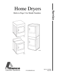
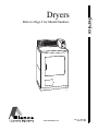
Dryers
Refer to Page 6 for Model Numbers
DRY1C
www.comlaundry.com
Part No. 505872R1
February 2001
Table of Contents
Section 1 – Safety Information
Locating an Authorized Servicer ............................4
Section 2 – Introduction
Customer Service ....................................................5
Nameplate Location ................................................5
Model Identification ................................................6
How Your Dryer Works ..........................................7
Section 3 – Troubleshooting
1.
2.
3.
4.
5.
6.
Dryer Does Not Run ........................................9
Motor Overload Protector Cycles Repeatedly .9
Motor Runs But Cylinder Does Not Turn ......10
Motor Does Not Stop .....................................10
Motor Starts When Door Is Closed ................10
Heating Element Does Not Heat and Burner
Does Not Ignite ..............................................11
7. Igniter Does Not Glow (Gas Supply Sufficient)
– Gas Models .................................................11
8. Burner Ignites and Goes Out Repeatedly
– Gas Models .................................................11
9. Igniter Glows But Burner Does Not Ignite
– Gas Models .................................................12
10. Heating Element or Burner Shuts Off
Prematurely ....................................................12
11. Heating Element Or Burner Repeatedly
Cycles Off On Limit Thermostat ...................13
12. Heating Element Or Burner Does
Not Shut Off ...................................................13
13. Clothes Do Not Dry .......................................13
14. Clothes Are Too Hot When Removed From
Dryer ..............................................................14
15. Computerized Audit Models ..........................15
Cycle Count “C” ...................................................17
No Slide Input “S” ................................................18
No Service Door Input “D” ...................................19
No Coin Vault Input “V” ......................................20
Section 4 – Grounding
16. Motor Mounting Bracket To Motor (Gas and
Electric Models) .............................................21
17. Motor Mounting Bracket to Exhaust Fan Cover
(Gas and Electric Models—with painted exhaust
fan cover) .......................................................21
18. Neutral at Terminal Block to Terminal Block
Bracket and From Terminal Block Bracket to
Control Housing (Electric Models Only) .......22
19. Power Cord to Terminal Block Bracket and
From Terminal Block Bracket to Control
Housing. Wall Receptacle Polarity Check (Gas
Models Only) .................................................23
20. Metered and Non-Metered Models — From
Terminal Block Bracket to Accumulator Bracket
or Timer (Depending on model) and from
Cabinet Top to Control Panel ........................24
21. Card Reader Models — From Terminal Block
Bracket to Cabinet Top, from Cabinet Top to
Timer and Cabinet Top to Control Panel .......25
Section 5 – Service Procedures
22. Control Panel, Temperature Switch, Push-toStart Switch and Indicator Light ....................27
23. Graphics Panel ...............................................28
24. Relays (Card Reader Models) ........................28
25. Timer ..............................................................30
26. Control Hood – Metered and Non-Metered
Models ............................................................32
27. Control Hood - Card Reader Models .............32
28. Control Hood Rear Cover ..............................32
29. Service Door, Accumulator and Counter –
Metered Models .............................................32
30. Meter Case .....................................................36
31. Timer Case .....................................................38
32. Cabinet Top – Non-Metered Models .............38
33. Cabinet Top – Metered Models .....................39
34. Cabinet Top – Card Reader Models ..............40
35. Lint Filter .......................................................41
36. Loading Door .................................................41
37. Inner and Outer Door Panels and
Door Handle ...................................................41
38. Door Striker ...................................................42
39. Door Seal .......................................................42
40. Front Panel and Panel Seal ............................43
41. Door Switch ...................................................43
42. Striker Catch ..................................................43
43. Door Hinge ....................................................44
44. Hold-Down Clips and Guide Lugs ................44
45. Burner System Components – Gas Models ...45
46. Burner Housing and Heat Shroud ..................48
47. Limit Thermostat ...........................................48
48. Heating Element ............................................48
49. High or Low Thermostat or Thermostat and
Heater .............................................................50
© Copyright 2001, Alliance Laundry Systems LLC
All rights reserved. No part of the contents of this book may be reproduced or transmitted in any form or by any means without
the expressed written consent of the publisher.
505872
© Copyright, Alliance Laundry Systems LLC – DO NOT COPY or TRANSMIT
1
50.
51.
52.
53.
54.
55.
56.
57.
58.
59.
60.
61.
62.
Front Air Duct ................................................52
Exhaust Duct ..................................................52
Motor and Exhaust Assembly ........................53
Front Bulkhead Assembly ..............................57
Cylinder Belt ..................................................58
Cylinder Assembly .........................................58
Rear Seal ........................................................59
Cylinder Roller ...............................................61
Outlet Cover ...................................................61
Rear Bulkhead and Heater Box Assemblies ..61
Terminal Block or Power Cord ......................63
Cabinet ...........................................................64
Base ................................................................66
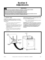
Section 6 – Adjustments
63. Leveling Legs .................................................67
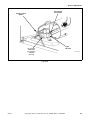
64. Burner Flame (Gas Models) ...........................68
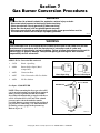
Section 7 – Gas Burner Conversion Procedures
65. Installing the No. 458P3 Kit ..........................72
66. Installing No. 459P3 Kit ................................76
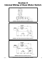
Section 8 – Internal Wiring of Dryer Motor
Switch .....................................................................79
Section 9 – Wiring Diagrams ............................81
Model EE1010
(Through Serial No. S6270865XG) .......................82
Model EE1010
(Starting Serial No. S6270866XG) ........................83
Model EG1020
(Through Serial No. S6270865XG) .......................84
Model EG1020
(Starting Serial No. S6270866XG) ........................85
Model EE1110 and EE1510
(Through Serial No. S6270865XG) .......................86
Model EE1110 and EE1510
(Starting Serial No. S6270866XG) ........................87
Model EG1120 and EG1520
(Through Serial No. S6270865XG) .......................88
Model EG1120 and EG1520
(Starting Serial No. S6270866XG) ........................89
Model EG1220
(Through Serial No. S6270865XG) .......................90
Model EG1220
(Starting Serial No. S6270866XG .........................91
Model EE1610 .......................................................92
Model EG1620.......................................................93
2
© Copyright, Alliance Laundry Systems LLC – DO NOT COPY or TRANSMIT
505872
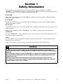
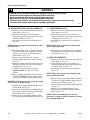
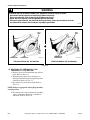
Section 1
Safety Information
Throughout this manual and on machine decals, you will find precautionary statements (“CAUTION,”
“WARNING,” and “DANGER”) followed by specific instructions. These precautions are intended for the personal
safety of the operator, user, servicer, and those maintaining the machine.
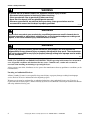
a DANGER
Danger indicates the presence of a hazard that will cause severe personal injury, death, or substantial property
damage if the danger is ignored.
a WARNING
Warning indicates the presence of a hazard that can cause severe personal injury, death, or substantial property
damage if the warning is ignored.
a CAUTION
Caution indicates the presence of a hazard that will or can cause minor personal injury or property damage if the
caution is ignored.
Additional precautionary statements (“IMPORTANT” and “NOTE”) are followed by specific instructions.
IMPORTANT
The word “IMPORTANT” is used to inform the reader of specific procedures where minor machine damage will
occur if the procedure is not followed.
NOTE
The word “NOTE” is used to communicate installation, operation, maintenance or servicing information that is
important but not hazard related.
In the interest of safety, some general precautions relating to the operation of this machine follow.
WARNING
• Failure to install, maintain, and/or operate this product according to the manufacturer’s
instructions may result in conditions which can produce serious injury, death and/or property
damage.
• Do not repair or replace any part of the product or attempt any servicing unless specifically
recommended or published in this Service Manual and that you understand and have the
skills to carry out.
• Whenever ground wires are removed during servicing, these ground wires must be
reconnected to ensure that the product is properly grounded and to reduce the risk of fire,
electric shock, serious injury, or death.
W006R1
505872
© Copyright, Alliance Laundry Systems LLC – DO NOT COPY or TRANSMIT
3
Section 1 Safety Information
WARNING
To reduce the risk of electric shock, fire, explosion, serious injury or death:
• Disconnect electric power to the dryer(s) before servicing.
• Close gas shut-off valve to gas dryer(s) before servicing.
• Never start the dryer(s) with any guards/panels removed.
• Whenever ground wires are removed during servicing, these ground wires must be
reconnected to ensure that the dryer is properly grounded.
W001R1
WARNING
Repairs that are made to your products by unqualified persons can result in hazards due to
improper assembly or adjustments subjecting you, or the inexperienced person making such
repairs, to the risk of serious injury, electrical shock, or death.
W007
WARNING
If you or an unqualified person perform service on your product, you must assume the
responsibility for any personal injury or property damage which may result. The manufacturer
will not be responsible for any injury or property damage arising from improper service and/or
service procedures.
W008
NOTE: The WARNINGS and IMPORTANT INSTRUCTIONS appearing in this manual are not meant to
cover all possible conditions and situations that may occur. Common sense, caution and care must be
exercised when installing, maintaining or operating the dryer.
Always contact your dealer, distributor, service agent or the manufacturer about any problems or conditions you do
not understand.
Locating an Authorized Servicer
Alliance Laundry Systems is not responsible for personal injury or property damage resulting from improper
service. Review all service information before beginning repairs.
Warranty service must be performed by an authorized technician, using authorized factory parts. If service is
required after the warranty expires, Alliance Laundry Systems also recommends contacting an authorized technician
and using authorized factory parts.
4
© Copyright, Alliance Laundry Systems LLC – DO NOT COPY or TRANSMIT
505872
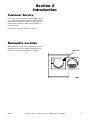
Section 2
Introduction
Customer Service
If literature or replacement parts are required, contact
the source from whom the machine was purchased or
contact Alliance Laundry Systems at (920) 748-3950
for the name and address of the nearest authorized
parts distributor.
For technical assistance, call (920) 748-3121.
Nameplate Location
When calling or writing about your product, be sure to
mention model and serial numbers. Model and serial
numbers are located on nameplate(s) as shown.
505872
© Copyright, Alliance Laundry Systems LLC – DO NOT COPY or TRANSMIT
NAMEPLATE
5
Section 2 Introduction
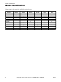
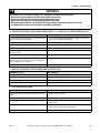
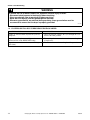
Model Identification
Information in this manual is applicable to these dryers.
Model
Numbers
Nonmetered
Models
EE1010
X
EG1020
X
Metered
Models
Card
Models
Audit
Models
Gas
Heat
X
X
EE1110
X
EG1120
X
EG1220
X
X
X
X
EE1510
X
X
EG1520
X
X
EE1610
X
X
EG1620
X
X
6
Electric
Heat
© Copyright, Alliance Laundry Systems LLC – DO NOT COPY or TRANSMIT
X
X
X
X
505872
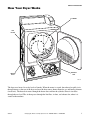
Section 2 Introduction
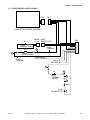
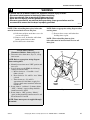
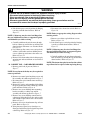
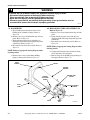
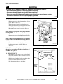
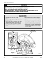
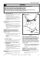
How Your Dryer Works
CYLINDER
LINT
FILTER
EXHAUST
FAN
HEATER
DUCT
DRY14S
The dryer uses heated air to dry loads of laundry. When the motor is started, the exhaust fan pulls air in
through louvers at the rear of the dryer and over the heat source (burner flame for gas and heating element
for electric). The heated air moves through the heater duct and into the cylinder, where it circulates
through the wet load. The air then passes through the lint filter, air duct, and exhaust fan, where it is
vented to the outdoors.
505872
© Copyright, Alliance Laundry Systems LLC – DO NOT COPY or TRANSMIT
7
Section 3
Troubleshooting
WARNING
To reduce the risk of electric shock, fire, explosion, serious injury or death:
• Disconnect electric power to the dryer(s) before servicing.
• Close gas shut-off valve to gas dryer(s) before servicing.
• Never start the dryer(s) with any guards/panels removed.
• Whenever ground wires are removed during servicing, these ground wires must be
reconnected to ensure that the dryer is properly grounded.
W001R1
IMPORTANT: Refer to appropriate model wiring diagram for aid in testing dryer components.
1. DRYER DOES NOT RUN
POSSIBLE CAUSE
TO CORRECT
Electrical power off, fuse blown, or power cord not • Be sure to check both fuses on electric models.
plugged in.
Loading door not closed or inoperative door switch. • Close door or test switch and replace if inoperative.
Motor overload protector has cycled.
• Wait two or three minutes for overload protector to reset.
If protector cycles repeatedly, refer to Paragraph 2.
Timer improperly set —nonmetered models.
• Reset timer.
Inoperative motor switch.
• Test switch and replace if inoperative.
Start circuit non completed.
• Press start switch button, or test switch and replace if
inoperative.
Inoperative motor.
• Test motor and replace if inoperative.
Inoperative timer—nonmetered models.
• Test timer and replace if inoperative.
Inoperative accumulator—metered models.
• Test accumulator and replace if inoperative.
Accumulator not being activated.
• Install slide extension.
Broken, loose, or incorrect wiring.
• Refer to appropriate wiring diagram.
Motor centrifugal mechanism sticky or plugged
• Remove dust or lint and spray with “SLYDE,” No. 131P4,
with lint.
to clean and lubricate.
2. MOTOR OVERLOAD PROTECTOR CYCLES REPEATEDLY
POSSIBLE CAUSE
TO CORRECT
Low voltage or high voltage.
• Refer to Installation Instructions (supplied with dryer) for
electrical requirements.
• Remove part of load. A normal washer load is a normal
dryer load.
• Check cylinder for binding and “out of round” condition.
Also check front and rear bulkheads for warping. Check
cylinder rollers for binding. Check cylinder seals and
glides for wear or damage.
• Replace drive motor.
Clothes load too large
Clothes cylinder is binding
Inoperative motor overload protector.
505872
© Copyright, Alliance Laundry Systems LLC – DO NOT COPY or TRANSMIT
9
Section 3 Troubleshooting
WARNING
To reduce the risk of electric shock, fire, explosion, serious injury or death:
• Disconnect electric power to the dryer(s) before servicing.
• Close gas shut-off valve to gas dryer(s) before servicing.
• Never start the dryer(s) with any guards/panels removed.
• Whenever ground wires are removed during servicing, these ground wires must be
reconnected to ensure that the dryer is properly grounded.
W001R1
3. MOTOR RUNS BUT CYLINDER DOES NOT TURN
POSSIBLE CAUSE
TO CORRECT
Motor drive pulley loose.
Broken cylinder belt.
Cylinder belt is upside down or twisted.
Clothes cylinder is binding.
•
•
•
•
Tighten setscrew, Figure 29.
Replace belt.
Install properly.
Check cylinder for binding and “out of round” condition.
• Check front and rear bulkheads for warping.
• Check cylinder rollers for binding.
Broken or disconnected idler lever spring.
• Check cylinder seals and glides for wear or damage.
• Replace or reconnect spring. Refer to Figure 29.
4. MOTOR DOES NOT STOP
POSSIBLE CAUSE
TO CORRECT
Inoperative door switch.
Inoperative timer – nonmetered models.
Inoperative accumulator—metered models.
Incorrect wiring.
•
•
•
•
Test switch and replace if inoperative.
Test timer and replace if inoperative.
Test accumulator and replace if inoperative.
Refer to appropriate wiring diagram.
5. MOTOR STARTS WHEN DOOR IS CLOSED
POSSIBLE CAUSE
TO CORRECT
Inoperative start switch.
• Test switch and replace if inoperative.
10
© Copyright, Alliance Laundry Systems LLC – DO NOT COPY or TRANSMIT
505872
Section 3 Troubleshooting
WARNING
To reduce the risk of electric shock, fire, explosion, serious injury or death:
• Disconnect electric power to the dryer(s) before servicing.
• Close gas shut-off valve to gas dryer(s) before servicing.
• Never start the dryer(s) with any guards/panels removed.
• Whenever ground wires are removed during servicing, these ground wires must be
reconnected to ensure that the dryer is properly grounded.
W001R1
6. HEATING ELEMENT DOES NOT HEAT AND BURNER DOES NOT IGNITE
POSSIBLE CAUSE
TO CORRECT
Improper or inadequate exhaust system.
• Refer to Installation Instructions (supplied with dryer)
for exhaust requirements.
• Check fuses or circuit breakers. (Electric models have two
fuses.)
• Reset switch, or test switch and replace if inoperative.
• Reset timer.
• Test thermostat and replace if inoperative.
• Replace element.
• Open partially closed gas shut-off valve, or correct low
gas pressure.
• Test switch and replace if inoperative.
• Test coils and replace if inoperative.
• Test igniter and replace if inoperative.
• Test sensor and replace if inoperative.
• Test thermal fuse and replace if inoperative.
• Test thermostat and replace if inoperative.
• Test timer and replace if inoperative.
• Test accumulator and replace if inoperative.
• Refer to appropriate wiring diagram.
Blown fuse or tripped circuit breaker.
FABRIC switch set at FLUFF, or inoperative.
Timer improperly set—nonmetered models.
Inoperative limit thermostat.
Electric Models: Inoperative heating element.
Gas Models: Insufficient gas supply.
Inoperative drive motor switch.
Gas Models: Inoperative gas valve coils.
Gas Models: Inoperative igniter.
Gas Models: Inoperative sensor.
Electric Models: Inoperative thermal fuse.
Inoperative cycling thermostat.
Inoperative timer—nonmetered models.
Inoperative accumulator—metered models.
Broken, loose, or incorrect wiring.
7. IGNITER DOES NOT GLOW (Gas Supply Sufficient) – GAS MODELS
POSSIBLE CAUSE
TO CORRECT
No power to power leads on valve.
Sensor failed with contacts open.
Igniter broken or open.
• Check electrical circuit, Paragraph 45.
• Replace sensor.
• Replace igniter.
8. BURNER IGNITES AND GOES OUT REPEATEDLY – GAS MODELS
POSSIBLE CAUSE
TO CORRECT
Burner heat not holding sensor contacts open.
Insufficient gas supply.
• Replace sensor.
• Check gas supply and pressure.
• Make sure gas shut-off valve is open.
505872
© Copyright, Alliance Laundry Systems LLC – DO NOT COPY or TRANSMIT
11
Section 3 Troubleshooting
WARNING
To reduce the risk of electric shock, fire, explosion, serious injury or death:
• Disconnect electric power to the dryer(s) before servicing.
• Close gas shut-off valve to gas dryer(s) before servicing.
• Never start the dryer(s) with any guards/panels removed.
• Whenever ground wires are removed during servicing, these ground wires must be
reconnected to ensure that the dryer is properly grounded.
W001R1
9. IGNITER GLOWS BUT BURNER DOES NOT IGNITE – GAS MODELS
POSSIBLE CAUSE
TO CORRECT
Sensor failed in closed position.
Open secondary coil or holding coil.
• Replace sensor.
• Replace gas valve (in-warranty), or replace coils (out-ofwarranty). Refer to Paragraph 45.
• Check gas supply and pressure.
Insufficient gas supply.
• Make sure gas shut-off valve is open.
10. HEATING ELEMENT OR BURNER SHUTS OFF PREMATURELY
POSSIBLE CAUSE
TO CORRECT
Improper or inadequate exhaust system.
• Refer to Installation Instructions (supplied with dryer)
for exhaust requirements.
• Open partially closed gas shut-off valve, or correct low
pressure.
• Refer to “Gas Burner Conversion Procedures” in this
manual to convert burner.
• Adjust flame.
• Momentarily connect a jumper wire across thermostat
terminals. If heating element heats or burner ignites when
jumper wire is connected, refer to Paragraph 11.
• Replace sensor. Adjust burner flame.
Gas Models: Insufficient gas supply.
Gas Models: Dryer not properly equipped for type
of gas used.
Gas Models: Improperly adjusted burner flame.
Cycling off on limit thermostat.
Gas models: Sensor contact closing prematurely.
Burner flame improperly adjusted.
Inoperative cycling thermostat.
Inoperative timer.
Broken, loose, or incorrect wiring.
12
• Test thermostat and replace if inoperative.
• Test timer and replace if inoperative.
• Refer to appropriate wiring diagram.
© Copyright, Alliance Laundry Systems LLC – DO NOT COPY or TRANSMIT
505872
Section 3 Troubleshooting
WARNING
To reduce the risk of electric shock, fire, explosion, serious injury or death:
• Disconnect electric power to the dryer(s) before servicing.
• Close gas shut-off valve to gas dryer(s) before servicing.
• Never start the dryer(s) with any guards/panels removed.
• Whenever ground wires are removed during servicing, these ground wires must be
reconnected to ensure that the dryer is properly grounded.
W001R1
11. HEATING ELEMENT OR BURNER REPEATEDLY CYCLES OFF ON LIMIT THERMOSTAT
POSSIBLE CAUSE
TO CORRECT
External exhaust system longer or providing greater
restriction than recommended.
Clogged lint filter.
Lint in internal dryer ductwork.
Lint in external exhaust system.
Hinged damper on exhaust system weather hood
not free to open.
Limit thermostat cycling at too low a temperature.
Air leak around loading door. (Door not sealing
properly against outer door seal due to damaged
seal or inoperative door catch.)
Air leak at front or rear cylinder seal.
• Refer to Installation Instructions (supplied with dryer)
for exhaust system requirements.
• Clean lint filter.
• Disassemble dryer and clean ductwork.
• Disassemble and clean exhaust system.
• Free hinged damper or replace weather hood
• Replace thermostat.
• Replace seal or catch.
• Check and replace seal if necessary.
12. HEATING ELEMENT OR BURNER DOES NOT SHUT OFF
POSSIBLE CAUSE
TO CORRECT
Improper motor switch.
Motor does not stop.
Incorrect wiring.
Heating element shorted.
•
•
•
•
Test switch and replace if inoperative.
Refer to Paragraph 4.
Refer to appropriate wiring diagram.
Remove element assembly and check for short.
13. CLOTHES DO NOT DRY
POSSIBLE CAUSE
TO CORRECT
Heating element does not heat or burner does not
ignite.
Too much water in articles being dried.
Clothes load too large.
• Refer to Paragraph 6.
Improper or inadequate exhaust system.
Heating element or burner shuts off prematurely.
505872
• Remove excess water.
• Remove part of load. A normal washer load is a normal
dryer load.
• Refer to INSTALLATION INSTRUCTIONS (supplied
with dryer) for exhaust requirements.
• Refer to Paragraph 10.
© Copyright, Alliance Laundry Systems LLC – DO NOT COPY or TRANSMIT
13
Section 3 Troubleshooting
WARNING
To reduce the risk of electric shock, fire, explosion, serious injury or death:
• Disconnect electric power to the dryer(s) before servicing.
• Close gas shut-off valve to gas dryer(s) before servicing.
• Never start the dryer(s) with any guards/panels removed.
• Whenever ground wires are removed during servicing, these ground wires must be
reconnected to ensure that the dryer is properly grounded.
W001R1
14. CLOTHES ARE TOO HOT WHEN REMOVED FROM DRYER
POSSIBLE CAUSE
TO CORRECT
Clothes are removed from dryer before cycle has
completed.
Inoperative cycling thermostat. Inoperative
thermostat heat on the DELICATE setting.
Inoperative accumulator or timer (not allowing
cool-down).
• Allow the dryer to complete the cycle through the cooldown to the OFF position.
• Test cycling thermostat or thermostat heater and replace
if inoperative.
• Test accumulator or timer and replace if inoperative.
14
© Copyright, Alliance Laundry Systems LLC – DO NOT COPY or TRANSMIT
505872
Section 3 Troubleshooting
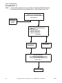
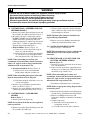
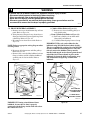
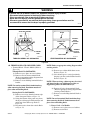
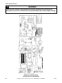
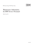
15. COMPUTERIZED AUDIT MODELS
HS 1
RS 1
1
2
3
4
1
2
3
4
35026 SENSOR BOARD ASSEMBLY
S2
34599
SERVICE DOOR
S1
F
56448
PLUG
1
2
56451
RECEPTACLE
RS 2
1
2
3
4
5
6
7
8
9
10
1
2
FLAG
TERMINAL
E
34536
COIN DRAWER
FLAG
TERMINAL
TIMER INPUT
CYCLE COUNT
120VAC
NEUTRAL
A
S3
B
34721
TRANSMIT
SWITCH
C
D
300Ω
34701
TRANSMIT LED
505872
© Copyright, Alliance Laundry Systems LLC – DO NOT COPY or TRANSMIT
15
Section 3 Troubleshooting
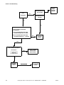
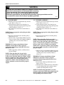
TRANSMIT
LIGHT
CONTINUOUSLY ON
NOT PULSING
REPLACE
AUDIT
CONTROL
BOARD
YES
TRANSMITS
CONTINUOUSLY ON
PULSING
NO
YES
CHECK TRANSMIT SWITCH
CHECK CONTINUITY BETWEEN
(2) TERMINALS
A. WITH TRANSMIT SWITCH BUTTON
PUSHED IN SHOULD BE “0” OHMS.
B. WITH TRANSMIT SWITCH BUTTON
RELEASED SHOULD BE “∞” INFINITE.
NO
REPLACE
TRANSMIT
SWITCH
YES
CHECK WIRING CONTINUITY
SEE FIGURE 1
NO
“A” TO RS 2 PIN 6
“B” TO “C”
“D” TO RS 2 PIN 5
CORRECT WIRING
OR REPLACE
WIRE HARNESS
YES
REPLACE
TRANSMIT
LIGHT
16
NO OPERATION
REPLACE
AUDIT CONTROL
BOARD
© Copyright, Alliance Laundry Systems LLC – DO NOT COPY or TRANSMIT
505872
Section 3 Troubleshooting
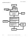
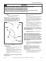
CYCLE COUNT “C”
NOTE: If collections are done on the dryer while the machines are in a cycle, the cycle count may not yet be
recorded, this count will appear on the next collection report. This happens if the collection occurs before
the end of the cycle on the dryer. Also, it must be noted that the method used for the cycle count is similar to
today's electro-mechanical counter and variances may occur due to the windows that exist. If the dryer is
unplugged during the last five minutes of the cycle, an extra count will appear. Also, if switch “C” is out of
adjustment, improper cycle counts may appear.
CHECK CYCLE COUNT WIRING BY
MEASURING CONTINUITY FROM:
WASHER: RED/YELLOW WIRE
AT TIMER TO RS2 PIN B
CORRECT
WIRING
OR REPLACE
AUDIT
HARNESS
DRYER: BLUE/RED (SWITCH “C”)
TO RS2 PIN B
NO
YES
CHECK TIMER SWITCH CLOSURE
DRYER:
1. REFER TO DRYER WIRING DIAGRAM.
2. CHECK FOR SWITCH CLOSURE ON
SWITCH “C”.
YES
NO
ADJUST SWITCH “C”
REPLACE AUDIT
CONTROL BOARD
AND RECHECK WITH
MICROWAND
MAINTENANCE
PROGRAM
1. DISCONNECT ELECTRICAL POWER.
2. REMOVE ACCUMULATOR FROM
METER CASE.
3. ACTIVATE ACCUMULATOR SWITCH
LEVER ONCE. (THIS IS THE LEVER
NORMALLY ACTIVATED BY THE COIN
SLIDE.)
4. CONNECT TEST METER PROBES TO
“COM” AND “N.O.” TERMINALS ON
SWITCH “C”.
5. TURN ADJUSTING SCREW ON SWITCH
“C” CLOCKWISE UNTIL METER
REGISTERS “INFINITE” “∞” (OPEN).
NOTE: ONCE THE ADJUSTMENT TOOL
HAS BEEN REMOVED, OBSERVE METER
TO INSURE READING OF INFINITE “∞”.
USE MICROWAND
MAINTENANCE PROGRAM
TO TEST CYCLE INPUT,
RUN MACHINE THROUGH
CYCLE
6. TURN ADJUSTMENT SCREW
COUNTERCLOCKWISE 1/4 TURN.
METER READING SHOULD BE “0”
OHMS (CLOSED).
7. REINSTALL ACCUMULATOR AND
RECONNECT ELECTRICAL POWER.
INPUT COUNT “C”
505872
© Copyright, Alliance Laundry Systems LLC – DO NOT COPY or TRANSMIT
17
Section 3 Troubleshooting
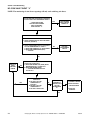
NO SLIDE INPUT “S”
NOTE: 1. Vertical slides required for correct operation of computerized AUDIT slide input.
2. Coin chute must be clear of any obstructions (i.e.; coins, foreign material, etc.)
USE MICROWAND MAINTENANCE
PROGRAM TO TEST SENSOR BOARD.
ADVANCE COUNT BY COIN SLIDE INSERTION
CHECK COUNT “S”
SENSOR AUDIT
BOARD CHECKS
(SEE NOTES
ABOVE)
YES (COUNT INCREMENTED)
NO
CHECK WIRING
1. CHECK CONNECTION OF RS1 TO HS1
(FIGURE 1)
2. CHECK CONTINUITY:
a) RS2 PIN 4 TO RS1 PIN 1
b) RS2 PIN 7 TO RS1 PIN 2
c) RS2 PIN 3 TO RS1 PIN 3
SEE FIGURE 1
NO
YES
CORRECT WIRING
OR REPLACE AUDIT
WIRE HARNESS
REPLACE AUDIT
SENSOR BOARD
RECHECK SLIDE INPUT
USE MICROWAND MAINTENANCE PROGRAM
TO TEST SENSOR BOARD.
ADVANCE COUNT BY COIN SLIDE INSERTION
CHECK COUNT “S”
REPLACE AUDIT
CONTROL BOARD
18
© Copyright, Alliance Laundry Systems LLC – DO NOT COPY or TRANSMIT
505872
Section 3 Troubleshooting
NO SERVICE DOOR INPUT “D”
CHECK SERVICE DOOR
MAGNET
MAGNET IN
PLACE MAGNET
IN SERVICE DOOR
NO MAGNET
USE MICROWAND MAINTENANCE PROGRAM
TO TEST COUNT ON SERVICE DOOR.
– READ COUNTS AND REPLACE
SERVICE DOOR
WAIT 30 SECONDS.
READ COUNTS “D”
YES
SERVICE DOOR
INPUT CHECKS
CORRECTLY
CHECK WIRING
1. CHECK CONNECTION AT PLUG AND
RECEPTACLE AT REED SWITCH HARNESS
TERMINATION.
CORRECT WIRING
OR REPLACE
AUDIT WIRE HARNESS
NO
2. CHECK AUDIT HARNESS CONTINUITY.
RECEPTACLE PIN 1 TO RS2 PIN 2
RECEPTACLE PIN 2 TO RS2 PIN 3
3. CHECK REED SWITCH CONTINUITY AT RS2
A. WITH SERVICE DOOR CLOSED
RS2 PIN 2 TO RS2 PIN 3 SHOULD BE
0 (ZERO) OHMS.
B. WITH SERVICE DOOR OPEN
RS2 PIN 2 TO RS2 PIN 3 SHOULD BE
“∞” INFINITE.
NO
REPLACE REED SWITCH
AND CHECK
OPERATION WITH
MICROWAND
MAINTENANCE
PROGRAM
YES
NO
REPLACE AUDIT
CONTROL BOARD
505872
© Copyright, Alliance Laundry Systems LLC – DO NOT COPY or TRANSMIT
19
Section 3 Troubleshooting
NO COIN VAULT INPUT “V”
NOTE: The monitoring of coin drawer openings will only work with long coin boxes.
USE MICROWAND MAINTENANCE PROGRAM
TO TEST COUNT ON COIN DRAWER SWITCH.
COIN DRAWER
INPUT CHECKS
CORRECTLY
YES
– READ COUNTS AND
REPLACE COIN DRAWER
WAIT 30 SECONDS.
READ COUNTS “V”
NO
CHECK WIRING OR CORRECT WIRING
1. CHECK CONNECTOR RS1. MUST BE MATED
WITH HS1. (FIGURE 1)
2. CHECK COIN DRAWER SWITCH CONTINUITY
AT FLAG TERMINATIONS “E” AND “F”.
A. WITH COIN DRAWER IN ”0” (ZERO) OHMS.
B. WITH COIN DRAWER OPEN (OUT)
“∞” INFINITE.
REPLACE
COIN DRAWER
SWITCH
NO
YES
REPLACE
AUDIT
CONTROL
BOARD
3. CHECK COIN DRAWER SWITCH CONTINUITY
AT RS2 PIN 3 TO RS2 PIN 1.
A. WITH COIN DRAWER IN 0 (ZERO) OHMS
YES
BETWEEN RS2 PIN 1 TO RS2 PIN 3.
B. WITH COIN DRAWER OPEN
“∞” INFINITE BETWEEN RS2 PIN 1
TO RS2 PIN 3
NO
YES
CHECK AUDIT HARNESS
CONTINUITY.
A. RS1 PIN 4 TO FLAG
TERMINATION “E”
(FIGURE 1)
B. RS2 PIN 1 TO FLAG
TERMINATION “F”
C. RS1 PIN 3 TO RS2 PIN 3.
NO
CHECK
CONTINUITY
FROM RS2 PIN 3
TO FLAG
TERMINATION
“E”
1. CORRECT WIRING.
2. REPLACE AUDIT
SENSOR BOARD.
3. REPLACE
HARNESS.
YES
20
© Copyright, Alliance Laundry Systems LLC – DO NOT COPY or TRANSMIT
505872
Section 4
Grounding
WARNING
To reduce the risk of electric shock, fire, explosion, serious injury or death:
• Disconnect electric power to the dryer(s) before servicing.
• Close gas shut-off valve to gas dryer(s) before servicing.
• Never start the dryer(s) with any guards/panels removed.
• Whenever ground wires are removed during servicing, these ground wires must be
reconnected to ensure that the dryer is properly grounded.
W001R1
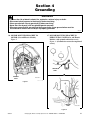
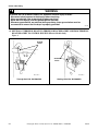
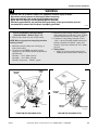
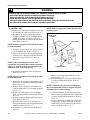
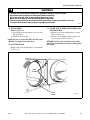
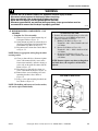
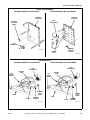
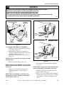
16. MOTOR MOUNTING BRACKET TO
MOTOR (Gas and Electric Models)
Figure 1
17. MOTOR MOUNTING BRACKET TO
EXHAUST FAN COVER (Gas and Electric
Models—with painted exhaust fan cover)
Figure 2 – (Ground wire not used on unpainted
covers)
GROUND
WIRE
GROUND
WIRE
DR019-GD-1
Figure 1
GROUND
WIRE
DR020-GD-1
Figure 2
505872
© Copyright, Alliance Laundry Systems LLC – DO NOT COPY or TRANSMIT
21
Section 4 Grounding
WARNING
To reduce the risk of electric shock, fire, explosion, serious injury or death:
• Disconnect electric power to the dryer(s) before servicing.
• Close gas shut-off valve to gas dryer(s) before servicing.
• Never start the dryer(s) with any guards/panels removed.
• Whenever ground wires are removed during servicing, these ground wires must be
reconnected to ensure that the dryer is properly grounded.
W001R1
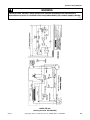
18. NEUTRAL AT TERMINAL BLOCK TO TERMINAL BLOCK BRACKET AND FROM TERMINAL
BLOCK BRACKET TO CONTROL HOUSING (Electric Models Only)
Figure 3
GROUND
WIRES
GROUND
WIRES
DR001-GD-1
DR025-GD-1
Through Serial No. S6270865XG
Starting Serial No. S6270866XG
Figure 3
22
© Copyright, Alliance Laundry Systems LLC – DO NOT COPY or TRANSMIT
505872
Section 4 Grounding
WARNING
To reduce the risk of electric shock, fire, explosion, serious injury or death:
• Disconnect electric power to the dryer(s) before servicing.
• Close gas shut-off valve to gas dryer(s) before servicing.
• Never start the dryer(s) with any guards/panels removed.
• Whenever ground wires are removed during servicing, these ground wires must be
reconnected to ensure that the dryer is properly grounded.
W001R1
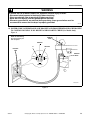
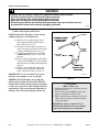
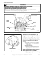
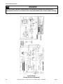
19. POWER CORD TO TERMINAL BLOCK BRACKET AND FROM TERMINAL BLOCK BRACKET
TO CONTROL HOUSING. WALL RECEPTACLE POLARITY CHECK (Gas Models Only)
Figure 4
NOTE: For determining
the correct polarity of a
wall receptacle.
GROUND
WIRE
GROUND
L1
NEUTRAL
NEUTRAL
SIDE
GROUND
WIRE
0
V.A.C.
120
V.A.C.
120 V.A.C.
DR026-GD-1
Figure 4
505872
© Copyright, Alliance Laundry Systems LLC – DO NOT COPY or TRANSMIT
23
Section 4 Grounding
WARNING
To reduce the risk of electric shock, fire, explosion, serious injury or death:
• Disconnect electric power to the dryer(s) before servicing.
• Close gas shut-off valve to gas dryer(s) before servicing.
• Never start the dryer(s) with any guards/panels removed.
• Whenever ground wires are removed during servicing, these ground wires must be
reconnected to ensure that the dryer is properly grounded.
W001R1
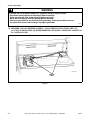
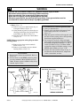
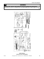
20. METERED AND NON-METERED MODELS — FROM TERMINAL BLOCK BRACKET TO
ACCUMULATOR BRACKET OR TIMER (DEPENDING ON MODEL) AND FROM CABINET TOP
TO CONTROL PANEL
DR023-GD-1
GROUND
WIRES
Figure 5
24
© Copyright, Alliance Laundry Systems LLC – DO NOT COPY or TRANSMIT
505872
Section 4 Grounding
WARNING
To reduce the risk of electric shock, fire, explosion, serious injury or death:
• Disconnect electric power to the dryer(s) before servicing.
• Close gas shut-off valve to gas dryer(s) before servicing.
• Never start the dryer(s) with any guards/panels removed.
• Whenever ground wires are removed during servicing, these ground wires must be
reconnected to ensure that the dryer is properly grounded.
W001R1
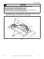
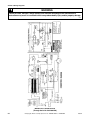
21. CARD READER MODELS — FROM TERMINAL BLOCK BRACKET TO CABINET TOP, FROM
CABINET TOP TO TIMER AND CABINET TOP TO CONTROL PANEL
GROUND
WIRES
DR024-GD-1
Figure 6
505872
© Copyright, Alliance Laundry Systems LLC – DO NOT COPY or TRANSMIT
25
Section 5
Service Procedures
WARNING
To reduce the risk of electric shock, fire, explosion, serious injury or death:
• Disconnect electric power to the dryer(s) before servicing.
• Close gas shut-off valve to gas dryer(s) before servicing.
• Never start the dryer(s) with any guards/panels removed.
• Whenever ground wires are removed during servicing, these ground wires must be
reconnected to ensure that the dryer is properly grounded.
W001R1
d. Loosen setscrew holding temperature switch
knob to shaft and pull knob off shaft.
e. Remove knurled nut holding temperature
switch to panel and remove switch.
f. Remove hex nut from PUSH-TO-START
switch and remove switch.
g. Squeeze locking tabs on INDICATOR LIGHT
and pull light out from pack of panel.
h. On Card Reader Models without panel lock,
remove plug button lock.
IMPORTANT: When reference to direction (right
or left) is made in this manual, it is from the
operator’s position facing the front of the dryer.
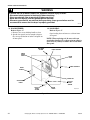
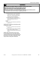
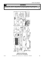
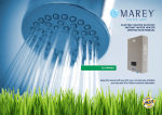
22. CONTROL PANEL, TEMPERATURE
SWITCH, PUSH-TO-START SWITCH AND
INDICATOR LIGHT
Refer to Figure 7
a. On Card Reader Models, remove panel lock
(if present).
NOTE: Several turns of the key may be required to
remove panel lock.
b. Remove two control panel attaching screws and
lift assembly off cabinet top.
c. Disconnect all wires to temperature switch,
PUSH-TO-START switch and INDICATOR
LIGHT and remove ground clip and screw
holding ground wire to cabinet top and control
panel.
NOTE: Refer to appropriate wiring diagram when
reconnecting wires.
505872
1.
2.
3.
4.
5.
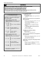
To Test Push-To-Start Switch
Unplug dryer from electrical supply and
disconnect wires from switch terminals.
Disconnect all wires from switch.
Set Volt-Ohm meter on OHMS scale and
calibrate at appropriate scale.
Place meter probes on switch terminals. You
should see an “infinite” reading on the meter.
With probes attached to switch, press the start
switch button. You should read “0” Ohms.
© Copyright, Alliance Laundry Systems LLC – DO NOT COPY or TRANSMIT
27
Section 5 Service Procedures
WARNING
To reduce the risk of electric shock, fire, explosion, serious injury or death:
• Disconnect electric power to the dryer(s) before servicing.
• Close gas shut-off valve to gas dryer(s) before servicing.
• Never start the dryer(s) with any guards/panels removed.
• Whenever ground wires are removed during servicing, these ground wires must be
reconnected to ensure that the dryer is properly grounded.
W001R1
To Test Temperature Switch
1. Disconnect all wires from temperature switch.
NOTE: Refer to appropriate wiring diagram
when rewiring switch.
2. Models equipped with No. 56576
Temperature Switch – Set test meter to read
OHMS and apply meter leads to terminals:
(1) L1 and C
L1 and 2
L2 and 2
2 and C
(2) L2 and C
2 AND C
(3) L1 and 2
2 and 1
}
}
}
“zero” reading in NORMAL
“zero” reading in
PERMANENT PRESS
“zero” reading in
DELICATE
3. Models equipped with No. 61512
Temperature Switch – Set test meter to read
OHMS and apply meter leads to terminals:
(1) L1 and 2
(2) L1 and 2
(3) L1 and 1
L1 and 2
}
}
}
23. GRAPHICS PANEL
Refer to Figure 7
a. Card Reader Models, remove panel lock (if
present).
NOTE: Several turns of the key may be required to
remove panel lock.
b. Remove two control panel attaching screws and
lift assembly off cabinet top.
c. Remove knurled nut holding temperature
switch to panel.
d. Remove hex nut from PUSH-TO-START
switch.
e. Card Reader Models without panel lock,
remove lock plug.
f. Remove graphics panel.
24. RELAYS (Card Reader Models)
Refer to Figure 7
a. Remove panel lock, (if present).
NOTE: Several turns of the key may be required to
remove panel lock.
b. Remove two control panel attaching screws and
lift assembly off cabinet top.
c. Disconnect wires from relay.
“zero” reading in NORMAL
NOTE: Refer to appropriate wiring diagram when
rewiring relays.
“zero” reading in
PERMANENT PRESS
“zero” reading in DELICATE
d. Remove two screws holding timer mounting
bracket assembly to cabinet top.
e. Remove two screws holding relay to mounting
bracket assembly.
Meter should give “no reading” from L1 to 1
and from L1 to 2 in FLUFF.
28
© Copyright, Alliance Laundry Systems LLC – DO NOT COPY or TRANSMIT
505872
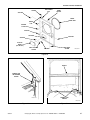
Section 5 Service Procedures
SCREW
CONTROL
HOOD
CONTROL HOOD
REAR COVER
LOCKWASHER
NUT
PHILLIPS HEAD
SCREW
LOCKWASHER
TEMPERATURE
SELECTOR
SWITCH
METER
CASE
HEX HEAD
SCREW
KNURLED
NUT
CAP
SCREW
LOCKWASHER
SETSCREW
NUT
PUSH-TO-START
SWITCH ASSEMBLY
INDICATOR
LIGHT
CONTROL KNOB
ASSEMBLY
NUT
CONTROL PANEL AND
BRACKET ASSEMBLY
CONTROL PANEL
OVERLAY
DR076-SV-1
METERED AND NON-METERED MODELS
CONTROL PANEL AND
BRACKET ASSEMBLY
CONTROL HOOD
ASSEMBLY
PUSH-TO-START
TEMPERATURE
SWITCH ASSEMBLY
SELECTOR
SWITCH
INDICATOR
LIGHT
LOCKWASHER
LOCKWASHER
SCREW
CONTROL KNOB
ASSEMBLY
SETSCREW
NUT
RETAINER
NUT
KNURLED
NUT
NUT
RELAY
SCREW
SCREW
COVER PLATE
TIMER
NUT
SCREW
SCREW
LOCK PLUG
CONTROL PANEL
OVERLAY
TIMER BRACKET
ASSEMBLY
RELAY
DR077-SV-1
CARD READER MODELS
Figure 7
505872
© Copyright, Alliance Laundry Systems LLC – DO NOT COPY or TRANSMIT
29
Section 5 Service Procedures
WARNING
To reduce the risk of electric shock, fire, explosion, serious injury or death:
• Disconnect electric power to the dryer(s) before servicing.
• Close gas shut-off valve to gas dryer(s) before servicing.
• Never start the dryer(s) with any guards/panels removed.
• Whenever ground wires are removed during servicing, these ground wires must be
reconnected to ensure that the dryer is properly grounded.
W001R1
(5) Remove ground screw holding ground
wire to timer.
(6) Disconnect wires from timer.
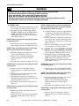
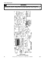
25. TIMER
a. Card Reader Models with timer mounted
behind control panel:
(1) Refer to Figure 7 for timer removal.
(2) Card Reader Models, remove panel lock
(if present).
(3) Several turns of the key may be required
to remove panel lock.Remove two control
panel attaching screws and lift assembly
off cabinet top.
(4) Remove two screws holding timer to timer
bracket.
NOTE: Refer to appropriate wiring diagram when
rewiring timer.
b. Nonmetered models:
(1) Refer to Figure 8 for timer removal.
(2) Loosen setscrew holding timer knob to
timer shaft and remove knob.
(3) Remove four screws and lockwasher
holding timer and plate to timer case.
CONTROL
HOOD
LOCKWASHER
NUT
CAPSCREW
LOCKWASHER
NUT
LOCKWASHER
GROUND WIRE
(GREEN)
TIMER
SPACER
TIMER
CASE
TIMER
PLATE
TIMER
ASSEMBLY
LOCKWASHER
INSTRUCTION
STICKER
LOCKNUT
TIMER KNOB
ASSEMBLY
SCREW
LOCKWASHER
RIVET
SCREW
SETSCREW
CABINET
TOP
WASHER
CAPSCREW
DR078-SV-1
Figure 8
30
© Copyright, Alliance Laundry Systems LLC – DO NOT COPY or TRANSMIT
505872
Section 5 Service Procedures
WARNING
To reduce the risk of electric shock, fire, explosion, serious injury or death:
• Disconnect electric power to the dryer(s) before servicing.
• Close gas shut-off valve to gas dryer(s) before servicing.
• Never start the dryer(s) with any guards/panels removed.
• Whenever ground wires are removed during servicing, these ground wires must be
reconnected to ensure that the dryer is properly grounded.
W001R1
NOTE: When reinstalling timer plate, lockwasher
must be between head of screw and plate.
(4) Pull timer and plate out of timer case as far
as wires will permit.
(5) Remove screw, lockwasher and locknut
holding ground wires to timer.
(6) Disconnect wires from timer.
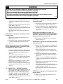
To Test Timer Contacts:
(Nonmetered Models - Refer to Figure 9)
1. Disconnect wires from timer, Figure 8, except
timer motor.
NOTE: Refer to appropriate wiring diagram when
rewiring timer.
(7) Remove three screws and lockwasher
holding timer to plate.
NOTE: When reinstalling timer to plate,
lockwasher must be between head of screw and
timer plate.
“L1”
“H”
“M”
NOTE: Refer to appropriate wiring diagram
when rewiring timer.
2. Manually rotate timer out of “OFF” position and
into cycle.
3. Set test meter to read OHMS. the following
readings should be found:
a. Motor circuit test – L1 and M = “zero”
Ohms (closed)
b. Heat circuit test – L1 and H = “zero” Ohms
(closed)
c. Timer motor test – L1 and N =
approximately 1100 Ohms or apply live
power to timer motor terminals and motor
should run.
4. Rotate timer to “cooldown” (5 minutes before
“OFF”). “Infinite” (open) reading should be
found between L1 and H.
5. Rotate timer to “OFF” position. “Infinite”
(open) reading should be found between L1 and
M and between L1 and H.
“N”
TIMER
MOTOR
WIRES
DR063-SV-1
Figure 9
NOTE: Timer motor power is supplied through
M terminal.
505872
© Copyright, Alliance Laundry Systems LLC – DO NOT COPY or TRANSMIT
31
Section 5 Service Procedures
WARNING
To reduce the risk of electric shock, fire, explosion, serious injury or death:
• Disconnect electric power to the dryer(s) before servicing.
• Close gas shut-off valve to gas dryer(s) before servicing.
• Never start the dryer(s) with any guards/panels removed.
• Whenever ground wires are removed during servicing, these ground wires must be
reconnected to ensure that the dryer is properly grounded.
W001R1
26. CONTROL HOOD – METERED AND NONMETERED MODELS
a. Remove two control panel attaching screws and
lift assembly off cabinet top. Refer to Figure 7.
b. Disconnect all wires to temperature switch,
PUSH-TO-START switch and INDICATOR
LIGHT and remove ground clip and screw
holding ground wire to cabinet top and control
panel, Figure 5. (Refer to appropriate wiring
diagram when reconnecting wires.)
c. Metered Models: (Refer to Figure 10)
(1) Insert key in service door lock on top of
meter case and unlock door.
(2) Lift rear end of service door approximately
45° off meter case to disengage notched
tabs with internal rib at top of meter case.
NOTE: When reinstalling service door and
accumulator, front end of door must be inserted at
about a 45° angle in order to engage notched tabs
with internal rib at top of meter case.
d. Non-metered models: (Refer to Figure 8)
(1) Remove four screws and lockwasher
holding timer and plate to timer case.
NOTE: When reinstalling timer plate, lockwasher
must be between head of screw and plate.
(2) Pull timer and plate out of timer case as far
as wires will permit.
e. Remove cap screw holding control hood to
meter case. Refer to Figure 7.
f. Remove two screws holding control hood to
cabinet top and lift hood off rear tabs, Figure 7.
27. CONTROL HOOD - CARD READER
MODELS
Refer to Figure 7
a. Remove panel lock (if present)
NOTE: Several turns of the key may be required to
remove panel lock.
b. Remove two control panel attaching screws and
lift assembly off cabinet top.
32
c. Cut wires from card reader control at the butt
splice connector, remove strain relief and pull
wires through rear of hood.
NOTE: The butt splice connector will need to be
replaced during reinstallation.
d. Remove two screws holding control hood to
cabinet top and lift hood off rear tabs.
28. CONTROL HOOD REAR COVER
a. Refer to Figure 7 for removal.
NOTE: The control hood rear cover is welded to the
control hood on card reader models and is not
removable.
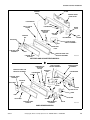
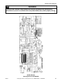
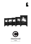
29. SERVICE DOOR, ACCUMULATOR AND
COUNTER –METERED MODELS
Refer to Figure 10
a. Insert key in service door lock on top of meter
case and unlock door.
b. Lift rear end of service door approximately 45°
off meter case to disengage notched tabs with
internal rib at top of meter case.
NOTE: When reinstalling service door and
accumulator, front end of door must be inserted at
about a 45° angle in order to engage notched tabs
with internal rib at top of meter case.
c. Disconnect accumulator wires at connectors.
NOTE: Refer to appropriate wiring diagram when
reconnecting wires.
d. Remove hex head ground screws holding green
ground wire to accumulator mounting bracket.
e. Remove two Phillips head screws and
lockwashers holding accumulator to mounting
bracket.
f. Counter (if present):
(1) Disconnect wire from terminal on
accumulator switch “C”.
(2) Cut other wire at butt splice connector.
© Copyright, Alliance Laundry Systems LLC – DO NOT COPY or TRANSMIT
505872
Section 5 Service Procedures
SERVICE DOOR
}
CONNECTORS
METERED MODELS
WITHOUT COUNTER
SWITCH
LEVER
GROUND WIRE
ACCUMULATOR
BRACKET
ACCUMULATOR
DR028-SV-1
SWITCHES
SERVICE DOOR
COUNTER
BRACKET
METERED MODELS
WITH COUNTER
(Through Serial No. S6348563YA
{
COUNTER
HEX HEAD
SCREW
PHILLIPS HEAD
SCREW
GROUND
WIRE
HEX HEAD
SCREW
PHILLIPS HEAD
SCREW
CONNECTORS
LOCKWASHER
ACCUMULATOR
BRACKET
DR029-SV-1
ACCUMULATOR
SWITCHES
METER
CASE
COUNTER
}
METERED MODELS
WITH COUNTER
(Starting Serial No. S6348563YA
DR079-SV-1
Figure 10
505872
© Copyright, Alliance Laundry Systems LLC – DO NOT COPY or TRANSMIT
33
Section 5 Service Procedures
WARNING
To reduce the risk of electric shock, fire, explosion, serious injury or death:
• Disconnect electric power to the dryer(s) before servicing.
• Close gas shut-off valve to gas dryer(s) before servicing.
• Never start the dryer(s) with any guards/panels removed.
• Whenever ground wires are removed during servicing, these ground wires must be
reconnected to ensure that the dryer is properly grounded.
W001R1
NOTE: The butt splice connector will need to be
replaced during reinstallation.
(3) Cut harness strap holding wires to bracket.
NOTE: Harness strap must be replaced during
reinstallation.
(4) Through Serial No. S6348564YA –
Remove two screws holding counter to
counter bracket.
Starting Serial No. S6348564YA – The
counter is mounted inside the meter case
with two-sided tape.
NOTE: When installing a new counter, remove the
protective backing from the tape located on
underside of new counter. Press the new counter
firmly in place. Tape on counter will reach full
adhesion after 24 hours.
34
© Copyright, Alliance Laundry Systems LLC – DO NOT COPY or TRANSMIT
505872
Section 5 Service Procedures
WARNING
To reduce the risk of electric shock, fire, explosion, serious injury or death:
• Disconnect electric power to the dryer(s) before servicing.
• Close gas shut-off valve to gas dryer(s) before servicing.
• Never start the dryer(s) with any guards/panels removed.
• Whenever ground wires are removed during servicing, these ground wires must be
reconnected to ensure that the dryer is properly grounded.
W001R1
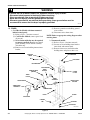
To Test Accumulator and Timer Motor:
(Metered Models – Refer to Figure 11)
1. Remove wires from one side of each switch.
NOTE: Refer to appropriate wiring diagram when
rewiring switches.
2. Manually advance timing cam to disengage it
from ratchet wheel.
3. Set meter to read OHMS and apply leads on
terminals of each switch in turn. You should read
the following:
Switch A – “zero” Ohms (closed)
Switch B – “zero” Ohms (closed)
Switch C (if present) – “infinite” (open)
4. Manually advance timing cam until it engages
with ratchet wheel and the first “click” is heard.
Switch B should now read “infinite” (open).
5. Continue to rotate timing cam until second
“click” is heard. Switch B should remain open.
Switch A should read “infinite” (open) and
Switch C (if present) should read “zero” Ohms
(closed).
6. Timing Motor:
a. Apply live power to timing motor leads.
Timing motor should advance timing cam.
TIMING
CAM
RATCHET
WHEEL
TIMING
CAM
RATCHET
WHEEL
DR064-SV-1
SWITCH
LEVER
SWITCHES
SWITCH
LEVER
SWITCHES
DR028-SV-1
THREE SWITCH ACCUMULATOR
TWO SWITCH ACCUMULATOR
Figure 11
505872
© Copyright, Alliance Laundry Systems LLC – DO NOT COPY or TRANSMIT
35
Section 5 Service Procedures
WARNING
To reduce the risk of electric shock, fire, explosion, serious injury or death:
• Disconnect electric power to the dryer(s) before servicing.
• Close gas shut-off valve to gas dryer(s) before servicing.
• Never start the dryer(s) with any guards/panels removed.
• Whenever ground wires are removed during servicing, these ground wires must be
reconnected to ensure that the dryer is properly grounded.
W001R1
30. METER CASE
a. Remove two control panel attaching screws and
lift assembly off cabinet top. Refer to Figure 7.
b. Disconnect all wires to temperature switch,
PUSH-TO-START switch and INDICATOR
LIGHT and remove ground clip and screw
holding ground wire to cabinet top and control
panel. Refer to Figure 5.
NOTE: Refer to appropriate wiring diagram when
rewiring switch.
METER CASE
SCREW
CAP SCREW
NOTE: Refer to appropriate wiring diagram when
reconnecting wires.
c. Insert key in service door lock on top of meter
case and unlock door. Refer to Figure 10.
d. Lift rear end of service door approximately 45°
off meter case to disengage notched tabs with
internal rib at top of meter case. Refer to
Figure 10.
NOTE: When reinstalling service door and
accumulator, front end of door must be inserted at
about a 45° angle in order to engage notched tabs
with internal rib at top of meter case.
e. Disconnect accumulator wires at connectors.
Refer to Figure 10.
NOTE: Refer to appropriate wiring diagram when
reconnecting wires.
f. Remove hex head ground screw holding green
ground wire to accumulator mounting bracket.
Refer to Figure 10.
g. Remove one hex head cap screw (right rear
corner) holding meter case to cabinet top. Refer
to Figure 12.
h. Remove nut, lockwasher and screw holding
meter case to right end of control hood. Refer to
Figure 12.
i. Remove two screws from bottom edge of front
panel. Refer to Figure 13.
j. Swing bottom of panel away from dryer to
disengage hold-down clips and guide lugs from
cabinet top. Refer to Figure 13.
k. Disconnect wires from door switch. Refer to
Figure 18.
36
DR030-SV-1
CARRIAGE BOLTS
Figure 12
l. Remove two cabinet top hold-down screws.
Refer to Figure 14.
m. Lift cabinet top to a vertical position by hinging
it on the rear hold-down bracket. Refer to
Figure 15.
NOTE: Cabinet top may be raised and hinged on
the rear hold-down brackets or supported against
wall behind dryer while servicing.
n. Carefully withdraw the wire harness through
hole in cabinet top and lift the entire cabinet top
assembly off the hold-down brackets. Refer to
Figure 15.
o. Lay the cabinet top assembly flat, remove two
carriage bolts, washers, lockwashers and nuts
holding meter case to cabinet top and remove
meter case. Refer to Figure 12.
© Copyright, Alliance Laundry Systems LLC – DO NOT COPY or TRANSMIT
505872
Section 5 Service Procedures
SCREW
HOLD-DOWN
CLIP
STICKER
DOOR
SWITCH
FRONT
PANEL SEAL
GUIDE
LUG
STRIKER
CATCH
STICKER
SUPPORT
LOCKNUT
STICKER
ACCESS
DOOR
(Gas Models)
PHILLIPS HEAD
SCREW
WASHER
HEX HEAD
SCREW
DR009-PT-1
Figure 13
BRACE
CABINET TOP
HOLD-DOWN
SCREW
DR031-SV-1
CABINET TOP
HINGES
DR032-SV-1
Figure 14
505872
Figure 15
© Copyright, Alliance Laundry Systems LLC – DO NOT COPY or TRANSMIT
37
Section 5 Service Procedures
WARNING
To reduce the risk of electric shock, fire, explosion, serious injury or death:
• Disconnect electric power to the dryer(s) before servicing.
• Close gas shut-off valve to gas dryer(s) before servicing.
• Never start the dryer(s) with any guards/panels removed.
• Whenever ground wires are removed during servicing, these ground wires must be
reconnected to ensure that the dryer is properly grounded.
W001R1
31. TIMER CASE
a. Remove two control panel attaching screws and
lift assembly off cabinet top. Refer to Figure 7.
b. Disconnect all wires to temperature switch,
PUSH-TO-START switch and INDICATOR
LIGHT and remove ground clip and screw
holding ground wire to cabinet top and control
panel. Refer to Figure 5.
NOTE: Refer to appropriate wiring diagram when
reconnecting wires.
c. Remove four screws and lockwasher holding
timer and plate to timer case. Refer to Figure 8.
NOTE: When reinstalling timer plate, lockwasher
must be between head of screw and plate.
NOTE: Cabinet top may be raised and hinged on
the rear hold-down brackets or supported against
wall behind dryer while servicing.
m. Carefully withdraw wire harness through hole
in cabinet top and lift the entire cabinet top
assembly off the hold-down brackets. Refer to
Figure 15.
n. Lay the cabinet top assembly flat and remove
two carriage bolts, washers, lockwashers and
nuts holding front of timer case to cabinet top.
Refer to Figure 8.
o. Remove screw holding rear of case to cabinet
top and remove case. Refer to Figure 8.
d. Pull timer and plate out of timer case as far as
wires will permit. Refer to Figure 8.
e. Remove screw, lockwasher and locknut
holding ground wires to timer. Refer to
Figure 8.
f. Disconnect wires from timer. Refer to Figure 8.
32. CABINET TOP – NON-METERED MODELS
a. Remove two control panel attaching screws and
lift assembly off cabinet top. Refer to Figure 7.
b. Disconnect all wires to temperature switch,
PUSH-TO-START switch and INDICATOR
LIHT and remove ground clip and screw
holding ground wire to cabinet top and control
panel. Refer to Figure 5.
NOTE: Refer to appropriate wiring diagram when
rewiring timer.
NOTE: Refer to appropriate wiring diagram when
reconnecting wires.
g. Remove cap screw, lockwashers and nut
holding timer case to control hood. Refer to
Figure 7.
h. Remove two screws from bottom edge of the
front panel. Refer to Figure 13.
i. Swing bottom of panel away from dryer to
disengage hold-down clips and guide lugs from
cabinet top. Refer to Figure 13.
j. Disconnect wires from door switch. Refer to
Figure 18.
c. Remove four screws and lockwasher holding
timer and plate to timer case. Refer to Figure 8.
NOTE: Refer to appropriate wiring diagram when
rewiring switch.
k. Remove two cabinet top hold-down screws.
Refer to Figure 14.
l. Lift cabinet top to a vertical position by hinging
it on the rear hold-down brackets. Refer to
Figure 15.
38
NOTE: When reinstalling timer plate, lockwasher
must be between head of screw and plate.
d. Pull timer and plate out of timer case as far as
wires will permit. Refer to Figure 8.
e. Remove screw, lockwasher and locknut
holding ground wires to timer. Refer to
Figure 8.
f. Disconnect wires from timer. Refer to Figure 8.
NOTE: Refer to appropriate wiring diagram when
rewiring timer.
g. Remove cap screw, lockwashers and nut
holding timer case to control hood. Refer to
Figure 7.
© Copyright, Alliance Laundry Systems LLC – DO NOT COPY or TRANSMIT
505872
Section 5 Service Procedures
WARNING
To reduce the risk of electric shock, fire, explosion, serious injury or death:
• Disconnect electric power to the dryer(s) before servicing.
• Close gas shut-off valve to gas dryer(s) before servicing.
• Never start the dryer(s) with any guards/panels removed.
• Whenever ground wires are removed during servicing, these ground wires must be
reconnected to ensure that the dryer is properly grounded.
W001R1
h. Remove two screws holding control hood to
cabinet top and lift hood off rear tabs. Refer to
Figure 7.
i. Remove two screws from bottom edge of front
panel. Refer to Figure 13.
j. Swing bottom of panel away from dryer to
disengage hold-down clips and guide lugs from
cabinet top. Refer to Figure 13.
k. Disconnect wires from door switch. Refer to
Figure 18.
NOTE: Refer to appropriate wiring diagram when
rewiring switch.
l. Remove two cabinet top hold-down screws.
Refer to Figure 14.
m. Lift cabinet top to a vertical position by hinging
it on the rear hold-down brackets. Refer to
Figure 15.
NOTE: Cabinet top may be raised and hinged on
the rear hold-down brackets or supported against
wall behind dryer while servicing.
n. Carefully withdraw wire harness through hole
in cabinet top and lift the top off the hold-down
brackets with timer case attached. Refer to
Figure 15.
o. Lay cabinet top flat and remove two cap
screws, washers, lockwashers and nuts holding
front of timer case to cabinet top. Refer to
Figure 8.
p. Remove screw holding rear of case to cabinet
top and remove case. Refer to Figure 8.
q. Remove brace from underside of cabinet top by
swinging one end toward front or rear. Refer to
Figure 15.
33. CABINET TOP – METERED MODELS
a. Remove two control panel attaching screws and
lift assembly off cabinet top. Refer to Figure 7.
b. Disconnect all wires to temperature switch,
PUSH-TO-START switch and INDICATOR
LIGHT and remove ground clip and screw
holding ground wire to cabinet top and control
panel. Refer to Figure 5.
505872
NOTE: Refer to appropriate wiring diagram when
reconnecting wires.
c. Insert key in service door lock on top of meter
case and unlock door. Refer to Figure 10.
d. Lift rear end of service door approximately 45°
off meter case to disengage notched tabs with
internal rib at top of meter case. Refer to
Figure 10.
NOTE: When reinstalling service door and
accumulator, front end of door must be inserted at
about a 45° angle in order to engage notched tabs
with internal rib at top of meter case.
e. Disconnect accumulator wires at connectors.
Refer to Figure 10.
NOTE: Refer to appropriate wiring diagram when
reconnecting wires.
f. Remove hex head ground screw holding green
ground wire to accumulator mounting bracket.
Refer to Figure 10.
g. Remove one hex head cap screw (right rear
corner) holding meter case to cabinet top. Refer
to Figure 12.
h. Remove nut, lockwasher and screw holding
meter case to right end of control hood. Refer to
Figure 12.
i. Remove two screws holding control hood to
cabinet top and lift hood off rear tabs. Refer to
Figure 7.
j. Remove two screws from bottom edge of front
panel. Refer to Figure 13.
k. Swing bottom of panel away from dryer to
disengage hold-down clips and guide lugs from
cabinet top. Refer to Figure 13.
l. Disconnect wires from door switch. Refer to
Figure 18.
NOTE: Refer to appropriate wiring diagram when
rewiring switch.
m. Remove two cabinet top hold-down screws.
Refer to Figure 14.
© Copyright, Alliance Laundry Systems LLC – DO NOT COPY or TRANSMIT
39
Section 5 Service Procedures
WARNING
To reduce the risk of electric shock, fire, explosion, serious injury or death:
• Disconnect electric power to the dryer(s) before servicing.
• Close gas shut-off valve to gas dryer(s) before servicing.
• Never start the dryer(s) with any guards/panels removed.
• Whenever ground wires are removed during servicing, these ground wires must be
reconnected to ensure that the dryer is properly grounded.
W001R1
n. Lift cabinet top to a vertical position by hinging
it on the rear hold-down brackets. Refer to
Figure 15.
NOTE: Cabinet top may be raised and hinged on
the rear hold-down brackets or supported against
wall behind dryer while servicing.
o. Carefully withdraw the wire harness through
hole in cabinet top and lift the top off the holddown brackets with meter case attached. Refer
to Figure 15.
p. Lay cabinet top flat, remove two carriage bolts,
washers, lockwashers and nuts holding meter
case to cabinet top and remove the meter case.
Refer to Figure 12.
q. Remove brace from underside of cabinet top by
swinging one end toward front or rear. Refer to
Figure 15.
34. CABINET TOP – CARD READER MODELS
a. Remove panel lock (if present). Refer to
Figure 7.
i. Disconnect wires from door switch. Refer to
Figure 18.
NOTE: Refer to appropriate wiring diagram when
rewiring switch.
j. Remove two cabinet top hold-down screws.
Refer to Figure 14.
k. Lift cabinet top to a vertical position by hinging
it on the rear hold-down brackets. Refer to
Figure 15.
NOTE: Cabinet top may be raised and hinged on
the rear hold-down brackets or supported against
wall behind dryer while servicing.
l. Carefully withdraw the wire harness through
hole in cabinet top and lift the top off the holddown brackets. Refer to Figure 15.
NOTE: The instruction plate located on the cabinet
top will need to be replaced when replacing the top.
NOTE: Several turns of the key may be required to
remove panel lock.
b. Remove two control panel attaching screws and
lift assembly off cabinet top. Refer to Figure 7.
c. Disconnect the wires from the timer and relays.
Refer to Figure 7.
d. Remove the screws and grounding clip holding
the green ground wire to the cabinet top, control
panel and timer. Refer to Figure 6.
e. Remove two screws holding timer mounting
bracket assembly to cabinet top and lift
assembly off cabinet top. Refer to Figure 7.
f. Remove two screws holding control hood to
cabinet top, lift hood off rear tabs and set to the
side with the reader control wires still attached.
Refer to Figure 7.
g. Remove two screws from bottom edge of front
panel. Refer to Figure 13.
h. Swing bottom of panel away from dryer to
disengage hold-down clips and guide lugs from
cabinet top. Refer to Figure 13.
40
© Copyright, Alliance Laundry Systems LLC – DO NOT COPY or TRANSMIT
505872
Section 5 Service Procedures
WARNING
To reduce the risk of electric shock, fire, explosion, serious injury or death:
• Disconnect electric power to the dryer(s) before servicing.
• Close gas shut-off valve to gas dryer(s) before servicing.
• Never start the dryer(s) with any guards/panels removed.
• Whenever ground wires are removed during servicing, these ground wires must be
reconnected to ensure that the dryer is properly grounded.
W001R1
35. LINT FILTER
Refer to Figure 16
a. Open loading door and remove screw on each
end of lint filter.
b. Lift filter out of air duct.
NOTE: Be sure to replace the filter with the words
“FRONT” facing the front of the dryer.
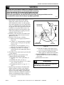
36. LOADING DOOR
37. INNER AND OUTER DOOR PANELS AND
DOOR HANDLE
a. Remove four screws holding hinges to door.
Refer to Figure 16.
b. Remove screws holding handle to door and
separate panels. Refer to Figure 17.
IMPORTANT: Do not over-tighten screws when
reinstalling door handle and avoid scratching inner
door panel.
Remove four screws holding hinges to door. Refer
to Figure 16.
HINGE
SCREWS
LINT
FILTER
DR029-IN-1
Figure 16
505872
© Copyright, Alliance Laundry Systems LLC – DO NOT COPY or TRANSMIT
41
Section 5 Service Procedures
WARNING
To reduce the risk of electric shock, fire, explosion, serious injury or death:
• Disconnect electric power to the dryer(s) before servicing.
• Close gas shut-off valve to gas dryer(s) before servicing.
• Never start the dryer(s) with any guards/panels removed.
• Whenever ground wires are removed during servicing, these ground wires must be
reconnected to ensure that the dryer is properly grounded.
W001R1
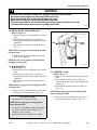
38. DOOR STRIKER
Refer to Figure 17
a. Remove two screws holding handle to door.
b. Spread door panels just far enough to depress
tabs on top and bottom of striker and push out
of inner panel.
39. DOOR SEAL
Refer to Figure 17
Open loading door and remove seal from inner
door panel.
NOTE: When replacing seal, be sure seal is not
stretched or distorted. Use a heat resistant adhesive
(such as Krazy Glue®) to adhere door seal to inner
door panel.
HEX HEAD
SCREW
DOOR STRIKER
INNER
DOOR
PANEL
DOOR
SEAL
DOOR ASSEMBLY
DOOR
HANDLE
SPEED NUT
OUTER DOOR
PANEL
PHILLIPS
HEAD
SCREW
PHILLIPS
HEAD
SCREW
DOOR
HINGE
DR034-SV-1
Figure 17
42
© Copyright, Alliance Laundry Systems LLC – DO NOT COPY or TRANSMIT
505872
Section 5 Service Procedures
WARNING
To reduce the risk of electric shock, fire, explosion, serious injury or death:
• Disconnect electric power to the dryer(s) before servicing.
• Close gas shut-off valve to gas dryer(s) before servicing.
• Never start the dryer(s) with any guards/panels removed.
• Whenever ground wires are removed during servicing, these ground wires must be
reconnected to ensure that the dryer is properly grounded.
W001R1
40. FRONT PANEL AND PANEL SEAL
Refer to Figure 13
a. Remove two screws from bottom edge of front
panel.
b. Swing bottom of panel away from dryer to
disengage hold-down clips and guide lugs from
cabinet top.
c. Disconnect wires from door switch. Refer to
Figure 18.
DOOR
SWITCH
TABS
NOTE: Refer to appropriate wiring diagram when
rewiring switch.
d. Remove front panel seal from flange around
inside of door opening.
NOTE: Be sure seal is properly positioned when
installing on front panel.
DR035-SV-1
41. DOOR SWITCH
Refer to Figure 13
a. Remove two screws from bottom edge of front
panel.
b. Swing bottom of panel away from dryer to
disengage hold-down clips and guide lugs from
cabinet top.
c. Disconnect wires from door switch. Refer to
Figure 18.
NOTE: Refer to appropriate wiring diagram when
rewiring switch.
d. Depress tabs on top and bottom of switch and
push out of front panel. Refer to Figure 18.
To Test Door Switch:
1. Disconnect wires from door switch.
Figure 18
42. STRIKER CATCH
Refer to Figure 13
a. Remove two screws from bottom edge of front
panel.
b. Swing bottom of panel away from dryer to
disengage hold-down clips and guide lugs from
cabinet top.
c. Disconnect wires from door switch. Refer to
Figure 18.
NOTE: Refer to the appropriate wiring diagram
when rewiring the switch.
d. Depress tabs on top and bottom of catch and
push out of front panel. Refer to Figure 18.
NOTE: Refer to appropriate wiring diagram
when rewiring switch.
2. Set meter to read OHMS and apply meter probes
on switch terminals with door closed. You
should get “zero” reading.
3. Open the door. Meter should read “infinite.”
505872
© Copyright, Alliance Laundry Systems LLC – DO NOT COPY or TRANSMIT
43
Section 5 Service Procedures
WARNING
To reduce the risk of electric shock, fire, explosion, serious injury or death:
• Disconnect electric power to the dryer(s) before servicing.
• Close gas shut-off valve to gas dryer(s) before servicing.
• Never start the dryer(s) with any guards/panels removed.
• Whenever ground wires are removed during servicing, these ground wires must be
reconnected to ensure that the dryer is properly grounded.
W001R1
44. HOLD-DOWN CLIPS AND GUIDE LUGS
Refer to Figure 13
a. Remove two screws from bottom edge of front
panel.
b. Swing bottom of panel away from dryer to
disengage hold-down clips and guide lugs from
cabinet top.
c. Disconnect wires from door switch. Refer to
Figure 18.
43. DOOR HINGE
a. Open loading door and remove four screws
holding door assembly to hinges. Refer to
Figure 16.
b. Remove two screws from bottom edge of front
panel. Refer to Figure 13.
c. Swing bottom of panel away from dryer to
disengage hold-down clips and guide lugs from
cabinet top. Refer to Figure 13.
d. Disconnect wires from door switch. Refer to
Figure 13.
NOTE: Refer to appropriate wiring diagram when
rewiring switch.
NOTE: Refer to appropriate wiring diagram when
rewiring switch.
d. Compress hold-down clips and remove from
slot in top flange of front panel.
e. Remove four screws holding four guide lugs to
front panel. Refer to Figure 13.
e. Remove four screws and locknuts holding
hinges to front panel. Refer to Figure 13.
HEAT
SHROUD
SCREW
BURNER
HOUSING
BURNER TUBE
SCREW
SENSOR
ATTACHING
SCREW
INLET
TUBE
DISCONNECT
BLOCK
SENSOR
NIPPLE
TAB
VALVE
UNION
NUT
DR036-SV-1
Figure 19
44
© Copyright, Alliance Laundry Systems LLC – DO NOT COPY or TRANSMIT
505872
Section 5 Service Procedures
WARNING
To reduce the risk of electric shock, fire, explosion, serious injury or death:
• Disconnect electric power to the dryer(s) before servicing.
• Close gas shut-off valve to gas dryer(s) before servicing.
• Never start the dryer(s) with any guards/panels removed.
• Whenever ground wires are removed during servicing, these ground wires must be
reconnected to ensure that the dryer is properly grounded.
W001R1
45. BURNER SYSTEM COMPONENTS – GAS
MODELS
a. Complete Gas Valve Assembly
(1) Remove two screws from bottom edge of
front panel. Refer to Figure 13.
(2) Swing bottom of panel away from dryer to
disengage hold-down clips and guide lugs
from cabinet top. Refer to Figure 13.
(3) Disconnect wires from door switch. Refer
to Figure 13.
NOTE: Refer to appropriate wiring diagram when
rewiring switch.
(4) Close gas shut-off valve, disconnect igniter
wires at disconnect blocks, sensor wires
from sensor terminals, and wires from gas
valve coils at the quick disconnect blocks.
Refer to Figure 19.
(5) Disconnect gas shut-off valve from gas
valve at the union nut. Refer to Figure 19.
(6) Remove three screws holding valve and
mounting bracket to base. Refer to
Figure 19.
(7) Lift gas valve and mounting bracket from
base. Refer to Figure 19.
NOTE: The holding and booster coil, and secondary
coil can be replaced individually.
To Test Gas Valve Coils:
1. Remove disconnect blocks from gas valve coils.
2. Set test meter to read OHMS and put meter
probes to terminals as follows:
a. Holding Coil (Refer to Figure 20)
Terminals 1 and 2 – Meter should read 1365
± 25 Ohms
b. Booster Coil (Refer to Figure 20)
Terminals 1 and 2 – Meter should read 560
± 25 Ohms.
c. Secondary Coil (Refer to Figure 20)
Terminals 4 and 5 – Meter should read 1220
± 50 Ohms.
NOTE: If meter registers any other readings than
that listed above, the respective coil should be
replaced.
TOP VIEW OF GAS VALVE
SECONDARY
COIL
4
5
1
2
3
HOLDING
AND BOOSTER
COIL
DR036-SV-1
Figure 20
505872
© Copyright, Alliance Laundry Systems LLC – DO NOT COPY or TRANSMIT
45
Section 5 Service Procedures
WARNING
To reduce the risk of electric shock, fire, explosion, serious injury or death:
• Disconnect electric power to the dryer(s) before servicing.
• Close gas shut-off valve to gas dryer(s) before servicing.
• Never start the dryer(s) with any guards/panels removed.
• Whenever ground wires are removed during servicing, these ground wires must be
reconnected to ensure that the dryer is properly grounded.
W001R1
b. Burner Tube, Igniter and Bracket
NOTE: Burner tube and igniter can be removed
without removing as valve and bracket.
(1) Remove one screw from right side of
burner housing holding burner tube in
place. Refer to Figure 23.
(2) Gently move burner tube toward rear of
dryer to disengage tab from slot on left side
of burner housing. Refer to Figure 19.
(3) Carefully rotate burner tube and igniter
counterclockwise so tab is at 8 o’clock
position.
(4) Move air shutter end of burner tube slightly
to right and CAREFULLY remove burner
tube and igniter assembly out through front
of dryer.
(5) Remove screw holding the igniter and
bracket to the burner tube and remove
igniter and bracket. Refer to Figure 21.
IMPORTANT: Use care in removal so as not to
damage or break igniter as it is very fragile.
IMPORTANT: Handle igniter by grasping the
white ceramic portion or bracket only. DO NOT
handle silicon carbide portion of igniter with hands
or allow any oil, grease or other foreign material to
contaminate it. Oil, grease and other impurities or
hairline cracks will cause the igniter to burn out.
ATTACHING
SCREW
CARBORANDUM
IGNITER AND
BRACKET
IGNITER
AND
BRACKET
ATTACHING
SCREW
NORTON
IGNITER AND
BRACKET
DR002-SV-1
Figure 21
To Test Igniter:
(Refer to Figure 21)
1. Disconnect igniter wires at disconnect block.
Refer to Figure 19.
2. Set test meter to read OHMS and put meter
probes on terminals of igniter wires.
3. Meter should register a reading of at least 40
Ohms. If meter registers less than 40 Ohms,
replace the igniter.
IMPORTANT: Always examine all wires,
terminals and connectors to be sure wiring is
proper before replacing any components.
46
© Copyright, Alliance Laundry Systems LLC – DO NOT COPY or TRANSMIT
505872
Section 5 Service Procedures
WARNING
To reduce the risk of electric shock, fire, explosion, serious injury or death:
• Disconnect electric power to the dryer(s) before servicing.
• Close gas shut-off valve to gas dryer(s) before servicing.
• Never start the dryer(s) with any guards/panels removed.
• Whenever ground wires are removed during servicing, these ground wires must be
reconnected to ensure that the dryer is properly grounded.
W001R1
c. Sensor, Figure 19
(1) Remove two screws from bottom edge of
front panel. Refer to Figure 13.
(2) Swing bottom of panel away from dryer to
disengage hold-down clips and guide lugs
from cabinet top. Refer to Figure 13.
(3) Disconnect wires from door switch. Refer
to Figure 18.
To Test Electrical Circuit to Ignition System:
1. Close gas shut-off valve.
2. Remove valve wire harness disconnect block
from holding and booster coil. Refer to
Figure 22.
3. Plug dryer power cord into wall receptacle, start
the dryer in a heat setting (refer to the Operating
Instructions supplied with dryer).
4. Set test meter to read AC voltage and apply
meter probes into terminals on the dryer harness
that would correspond to terminals “1” and “2”
on the coil. Refer to Figure 22. Meter should
register line voltage in all fabric settings, except
FLUFF which should read “zero” VAC.
5. If meter does not read line voltage in step “d”,
check motor switch, thermostats, temperature
switch, accumulator, or timer.
NOTE: Refer to appropriate wiring diagram when
rewiring switch.
(4) Remove wires from sensor terminals.
Refer to Figure 19.
(5) Remove screw holding sensor to burner
housing. Refer to Figure 19.
To Test Sensor:
1. Remove wires from sensor terminals. Refer to
Figure 19.
2. Set test meter to read OHMS, put meter probes
on sensor terminals. Meter should read “zero”
Ohms. If meter registers an Ohm reading of any
amount, replace sensor.
1
SECONDARY
COIL
2
120 VOLT, 60 HERTZ
ELECTRICAL SUPPLY LINE
3
HOLDING COIL
AND
BOOSTER COIL
DR062-SV-1
DR061-SV-1
WIRING SCHEMATIC
Figure 22
505872
© Copyright, Alliance Laundry Systems LLC – DO NOT COPY or TRANSMIT
47
Section 5 Service Procedures
WARNING
To reduce the risk of electric shock, fire, explosion, serious injury or death:
• Disconnect electric power to the dryer(s) before servicing.
• Close gas shut-off valve to gas dryer(s) before servicing.
• Never start the dryer(s) with any guards/panels removed.
• Whenever ground wires are removed during servicing, these ground wires must be
reconnected to ensure that the dryer is properly grounded.
W001R1
46. BURNER HOUSING AND HEAT SHROUD
a. Remove two screws from bottom edge of front
panel. Refer to Figure 13.
b. Swing bottom of panel away from dryer to
disengage hold-down clips and guide lugs from
cabinet top. Refer to Figure 13.
c. Disconnect wires from door switch. Refer to
Figure 18.
NOTE: Refer to appropriate wiring diagram when
rewiring switch.
d. Disconnect igniter wires at disconnect blocks,
sensor wires from sensor terminals, and wires
from gas valve coils at the quick disconnect
blocks. Refer to Figure 19.
e. Remove screw from right side of burner
housing, holding burner tube in place. Refer to
Figure 23.
f. Gently move burner tube toward rear of dryer to
disengage tab from slot on left side of burner
housing. Refer to Figure 19.
g. Carefully rotate burner tube and igniter
counterclockwise so tab is at 8 o’clock
position.
h. Move air shutter end of burner tube slightly to
right and CAREFULLY remove burner tube
and igniter assembly out through front of dryer.
IMPORTANT: The igniter is very fragile. Be careful
not to damage it during removal.
i. Remove screw holding burner housing to heat
shroud. Refer to Figure 19.
j. Remove screw holding front of burner housing
to dryer base and remove housing out through
front of dryer. Refer to Figure 23.
k. Remove two screws holding shroud to heater
box and take shroud out through front of dryer.
48
47. LIMIT THERMOSTAT
a. Remove two screws from bottom edge of front
panel. Refer to Figure 13.
b. Swing bottom of panel away from dryer to
disengage hold-down clips and guide lugs from
cabinet top. Refer to Figure 13.
c. Disconnect wires from door switch. Refer to
Figure 18.
NOTE: Refer to the appropriate wiring diagram
when rewiring the switch.
d. Disconnect wires and remove screws attaching
limit thermostat to burner housing or element
plate. Refer to Figure 23.
48. HEATING ELEMENT
a. Remove two screws from bottom edge of front
panel. Refer to Figure 13.
b. Swing bottom of panel away from dryer to
disengage hold-down clips and guide lugs from
cabinet top. Refer to Figure 13.
c. Disconnect wires from door switch. Refer to
Figure 18.
NOTE: Refer to the appropriate wiring diagram
when rewiring the switch.
d. Remove two screws holding element and plate
to heater box and pull element down and away
from heater box. Refer to Figure 23.
e. Disconnect wires from element and plate. Refer
to Figure 23.
f. Remove screws holding thermostat (and
thermal fuse, if present) to element and plate.
Refer to Figure 23.
NOTE: When reassembling, be sure all wire
connectors are tight on element terminals, thermal
fuse and limit thermostat.
© Copyright, Alliance Laundry Systems LLC – DO NOT COPY or TRANSMIT
505872
Section 5 Service Procedures
ELECTRIC MODELS
THROUGH SERIAL NO. S6270865XG
STARTING SERIAL NO. S6270866XG
ELEMENT
AND PLATE
ELEMENT
AND PLATE
LIMIT
THERMOSTAT
ELEMENT
ATTACHING
SCREW
LIMIT
THERMOSTAT
ELEMENT
ATTACHING
SCREW
DR080-SV-1
THERMAL
FUSE
DR003-SV-1
GAS MODELS
STARTING SERIAL NO. S6333960XM
THROUGH SERIAL NO. S6333959XM
LIMIT
THERMOSTAT
LIMIT
THERMOSTAT
GAS
VALVE
HANDLE
BURNER
TUBE
GAS
VALVE
HANDLE
BURNER
TUBE
BURNER
TUBE
SCREW
BASE
SCREW
BURNER
TUBE
SCREW
BASE
BURNER
HOUSING
SCREW
DR039-SV-1
BURNER
HOUSING
DR001-SV-1
Figure 23
505872
© Copyright, Alliance Laundry Systems LLC – DO NOT COPY or TRANSMIT
49
Section 5 Service Procedures
WARNING
To reduce the risk of electric shock, fire, explosion, serious injury or death:
• Disconnect electric power to the dryer(s) before servicing.
• Close gas shut-off valve to gas dryer(s) before servicing.
• Never start the dryer(s) with any guards/panels removed.
• Whenever ground wires are removed during servicing, these ground wires must be
reconnected to ensure that the dryer is properly grounded.
W001R1
FELT
SEAL
FELT
SEAL
HIGH
THERMOSTAT
LOW
THERMOSTAT
DR040-SV-1
THROUGH SERIAL NO. S6270865XG
THERMOSTAT
AND HEATER
DR004-SV-1
STARTING SERIAL NO. S6270866XG
Figure 24
49. HIGH OR LOW THERMOSTAT OR
THERMOSTAT AND HEATER
a. Remove two screws from bottom edge of front
panel. Refer to Figure 13.
b. Swing bottom of panel away from dryer to
disengage hold-down clips and guide lugs from
cabinet top. Refer to Figure 13.
c. Disconnect wires from door switch. Refer to
Figure 18.
NOTE: Refer to appropriate wiring diagram when
rewiring switch.
d. Disconnect wires, remove thermostat attaching
screws and remove thermostat or thermostat
and heater. Refer to Figure 24.
50
© Copyright, Alliance Laundry Systems LLC – DO NOT COPY or TRANSMIT
505872
Section 5 Service Procedures
WARNING
To reduce the risk of electric shock, fire, explosion, serious injury or death:
• Disconnect electric power to the dryer(s) before servicing.
• Close gas shut-off valve to gas dryer(s) before servicing.
• Never start the dryer(s) with any guards/panels removed.
• Whenever ground wires are removed during servicing, these ground wires must be
reconnected to ensure that the dryer is properly grounded.
W001R1
To Test Cycling or Limit Thermostat:
1. Disconnect wires from thermostat.
NOTE: Refer to appropriate wiring diagram
when rewiring thermostat.
2. Cycling Thermostat (S.P.S.T.) or Limit
Thermostat
a. Set meter to read OHMS.
b. Apply meter probes to the thermostat
terminals.
c. Meter should read “infinite.”
Cycling Thermostat (S.P.D.T.)
a. Set meter to read OHMS.
b. Apply meter probes to terminals 1 and 3,
meter should read “infinite”.
c. Remove screws holding thermostat to
exhaust fan cover.
d. Heat thermostat with a small flame until a
distinct “click” is heard, then immediately
apply meter probes to terminals 1 and 3;
meter should read “zero”.
To Test Thermal Fuse:
(Electric Models)
1. Disconnect wires from thermal fuse.
NOTE: Refer to appropriate wiring diagram
when rewiring thermal fuse.
2. Set meter to read OHMS. Apply meter probes to
the thermal fuse terminals, meter should read
“infinite”. If the meter does not register any
Ohms, replace both the thermal fuse and the
limit thermostat.
To Test Thermostat Heater:
1. Disconnect wires from thermostat heater.
NOTE: Refer to appropriate wiring diagram
when rewiring thermostat heater.
2. Set meter to read OHMS. Apply meter probes to
the thermostat heater terminals, meter should
read 1,600 Ohms ± 160 Ohms cold.
505872
© Copyright, Alliance Laundry Systems LLC – DO NOT COPY or TRANSMIT
51
Section 5 Service Procedures
WARNING
To reduce the risk of electric shock, fire, explosion, serious injury or death:
• Disconnect electric power to the dryer(s) before servicing.
• Close gas shut-off valve to gas dryer(s) before servicing.
• Never start the dryer(s) with any guards/panels removed.
• Whenever ground wires are removed during servicing, these ground wires must be
reconnected to ensure that the dryer is properly grounded.
W001R1
50. FRONT AIR DUCT
a. Remove two screws from bottom edge of front
panel. Refer to Figure 13.
b. Swing bottom of panel away from dryer to
disengage hold-down clips and guide lugs from
cabinet top. Refer to Figure 13.
c. Disconnect wires from door switch. Refer to
Figure 18.
HEX
HEAD
SCREWS
PHILLIPS
HEAD
SCREWS
HEX
HEAD
SCREWS
NOTE: Refer to appropriate wiring diagram when
rewiring switch.
d. Remove two screws from lint filter and lift filter
out of bulkhead. Refer to Figure 16.
SLOT
HEX HEAD
SCREWS
AIR
DUCT
NOTE: When installing lint filter, be sure to install
the filter with the words “FRONT” facing the front
of the dryer.
CABINET
ATTACHING SCREWS
e. Remove four screws holding duct to front
bulkhead and remove air duct. Refer to
Figure 25.
NOTE: When reassembling, be sure felt seal on
exhaust fan cover makes air tight seal on flange of
duct. Refer to Figure 24.
51. EXHAUST DUCT
a. Disconnect electric power, vent (and gas line if
necessary) and move unit to gain access to rear
of dryer.
b. Remove screw holding bracket on exhaust duct
to rear of cabinet. Refer to Figure 26.
c. Pull duct out through rear of cabinet.
DR005-SV-1
Figure 25
ACCESS
PLATE
MOUNTING BRACKET
ATTACHING SCREWS
GROUND
SCREW
EXHAUST
DUCT
SCREW
DR042-SV-1
Figure 26
52
© Copyright, Alliance Laundry Systems LLC – DO NOT COPY or TRANSMIT
505872
Section 5 Service Procedures
WARNING
To reduce the risk of electric shock, fire, explosion, serious injury or death:
• Disconnect electric power to the dryer(s) before servicing.
• Close gas shut-off valve to gas dryer(s) before servicing.
• Never start the dryer(s) with any guards/panels removed.
• Whenever ground wires are removed during servicing, these ground wires must be
reconnected to ensure that the dryer is properly grounded.
W001R1
CORRECT WAY
COVER
ATTACHING SCREWS
EXHAUST
FAN COVER
IDLER
PULLEY
IDLER
LEVER
MOTOR
PULLEY
GROUND
WIRE
(If present)
MOTOR MOUNT
ATTACHING
SCREWS
INCORRECT WAY
DR040-SV-1
Figure 27
52. MOTOR AND EXHAUST ASSEMBLY
a. Remove two screws from bottom edge of front
panel. Refer to Figure 13.
b. Swing bottom of panel away from dryer to
disengage hold-down clips and guide lugs from
cabinet top. Refer to Figure 13.
c. Disconnect wires from door switch. Refer to
Figure 18.
NOTE: Refer to appropriate wiring diagram when
rewiring switch.
IDLER
PULLEY
IDLER
LEVER
BELT ON WRONG
SIDE OF IDLER
LEVER
MOTOR
PULLEY
DR043-SV-1
Figure 28
d. Remove lint filter. Refer to Figure 16.
NOTE: When installing lint filter, be sure to install
the filter with the words “FRONT” facing the front
of the dryer.
e. Remove screws holding air duct to front
bulkhead and remove air duct. Refer to
Figure 25.
NOTE: When reassembling, be sure felt seal on
exhaust fan cover makes airtight seal on flange of
air duct. Refer to Figure 24.
505872
f. Disconnect wires from thermostats. Refer to
Figure 27.
NOTE: Refer to appropriate wiring diagram when
rewiring thermostats, or thermostat and heater.
g. Remove cylinder belt from idler and motor
pulleys. Refer to Figure 28.
h. Remove two screws holding motor mounting
bracket to dryer base. Refer to Figure 27. Then
pull complete assembly out through front of
dryer.
© Copyright, Alliance Laundry Systems LLC – DO NOT COPY or TRANSMIT
53
Section 5 Service Procedures
WARNING
To reduce the risk of electric shock, fire, explosion, serious injury or death:
• Disconnect electric power to the dryer(s) before servicing.
• Close gas shut-off valve to gas dryer(s) before servicing.
• Never start the dryer(s) with any guards/panels removed.
• Whenever ground wires are removed during servicing, these ground wires must be
reconnected to ensure that the dryer is properly grounded.
W001R1
MOTOR
SWITCH
SETSCREW
MOTOR
PULLEY
MOTOR
CLAMP
TRU-ARC
RING
IDLER
PULLEY
GROUND
WIRE
IDLER
SPRING
DR044-SV-1
Figure 29
IMPORTANT: When reinstalling motor and
exhaust assembly, be sure wire harness on right side
is clipped to motor mounting bracket and is routed
along dryer base (between motor mounting bracket
and right side of cabinet). Refer to Figure 27. Tab on
rear of motor mounting bracket must be slid into
slot in dryer base. Be sure the belt has been installed
on the correct side of the idler lever. Refer to
Figure 28.
i. Motor pulley and idler pulley assemblies
(1) Refer to Figure 29 for motor and idler
pulley removal.
j. Impeller and housing
(1) Remove screw holding ground wire (if
present) to exhaust fan cover. Refer to
Figure 27.
EXHAUST HOUSING
ATTACHING SCREWS
DR045-SV-1
Figure 30
NOTE: Ground wire must be routed as shown in
Figure 2 (Refer to Section 4, Grounding).
(2) Remove screws holding cover to housing.
Refer to Figure 27.
54
© Copyright, Alliance Laundry Systems LLC – DO NOT COPY or TRANSMIT
505872
Section 5 Service Procedures
WARNING
To reduce the risk of electric shock, fire, explosion, serious injury or death:
• Disconnect electric power to the dryer(s) before servicing.
• Close gas shut-off valve to gas dryer(s) before servicing.
• Never start the dryer(s) with any guards/panels removed.
• Whenever ground wires are removed during servicing, these ground wires must be
reconnected to ensure that the dryer is properly grounded.
W001R1
(3) Hold motor pulley securely and unthread
impeller from motor shaft. (Right hand
thread.) Use a 7/8 inch, 6 point socket to
aid in the removal of the impeller.
(4) Remove three screws (and washers if
present) holding the exhaust housing to the
motor mounting bracket. Refer to
Figure 30.
k. Motor
(1) Disconnect wires from motor switch. Refer
to Figure 29.
NOTE: Refer to appropriate wiring diagram when
rewiring motor switch.
(2) Disconnect ground wire from motor. Refer
to Figure 29.
(3) Pry two motor clamps off motor mounting
bracket with screwdriver. Refer to
Figure 29. Then lift motor out of mounting
bracket.
NOTE: When replacing motor, motor switch
location should be at 10 o’clock position with the
positioning tab on the motor engaged with the notch
in the motor bracket. Refer to appropriate wiring
diagram when rewiring motor switch leads.
505872
© Copyright, Alliance Laundry Systems LLC – DO NOT COPY or TRANSMIT
55
Section 5 Service Procedures
WARNING
To reduce the risk of electric shock, fire, explosion, serious injury or death:
• Disconnect electric power to the dryer(s) before servicing.
• Close gas shut-off valve to gas dryer(s) before servicing.
• Never start the dryer(s) with any guards/panels removed.
• Whenever ground wires are removed during servicing, these ground wires must be
reconnected to ensure that the dryer is properly grounded.
W001R1
To Test Drive Motor:
(Refer to Figure 31)
4. Put test meter probes on terminal 5 and motor
1. Disconnect wires from motor switch.
frame. Meter should register “no reading” or
NOTE: Refer to appropriate wiring diagram when
infinite.
rewiring motor switch.
5. Put test meter probes on terminals 4 and 6. Meter
should register “no reading” or infinite. Manually
2. Put test meter probes on terminals 4 and 5. Meter
flex the centrifugal switch in motor and meter
should read approximately one on Ohm scale.
should read approximately two on Ohm scale.
3. Put test meter probes on terminal 4 and motor
6.
Put test meter probes on terminals 1 and 2. Meter
frame. Meter should register “no reading” or
should
register “no reading.” Manually flex the
infinite.
centrifugal switch in motor and meter should
read “zero” Ohms.
MOTOR
SWITCH
MOTOR AND
EXHAUST ASSEMBLY
DRIVE
MOTOR
GROUND
WIRE
DR060-SV-1
Figure 31
56
© Copyright, Alliance Laundry Systems LLC – DO NOT COPY or TRANSMIT
505872
Section 5 Service Procedures
WARNING
To reduce the risk of electric shock, fire, explosion, serious injury or death:
• Disconnect electric power to the dryer(s) before servicing.
• Close gas shut-off valve to gas dryer(s) before servicing.
• Never start the dryer(s) with any guards/panels removed.
• Whenever ground wires are removed during servicing, these ground wires must be
reconnected to ensure that the dryer is properly grounded.
W001R1
53. FRONT BULKHEAD ASSEMBLY
a. Remove two screws from bottom edge of front
panel. Refer to Figure 26.
b. Swing bottom of the panel away from dryer to
disengage hold-down clips and guide lugs from
cabinet top. Refer to Figure 26.
c. Disconnect wires from door switch. Refer to
Figure 18.
NOTE: Refer to appropriate wiring diagram when
rewiring switch.
d. Disengage belt from motor and idler pulleys.
Refer to Figure 28.
e. Remove four screws holding bulkhead to front
flange of cabinet and lift complete bulkhead
assembly out of slots in cabinet. Refer to
Figure 32.
f. Cylinder Glides (Refer to Figure 33)
(1) Remove two screws holding glide(s) to
each glide bracket.
g. Front Cylinder Seal (Refer to Figure 33)
(1) Pull front cylinder seal out from under
flanged edge of bulkhead.
(2) Carefully unhook spring from seal strap.
IMPORTANT: The seal can be adhered to the
bulkhead using 3M-1300 Sealant (obtain locally).
This is accomplished by applying a bead of 3M-1300
Sealant around the entire flanged area where the
felt seal contacts the bulkhead. Strap must be
installed with cupped surface down against the seal
to hold the felt seal more firmly in place on the
bulkhead. Seal must be held securely under strap
and folded under flanged edge around entire
bulkhead.
FRONT
BULKHEAD
SCREWS
FELT
SEAL
SCREWS
SEAL STRAP
(Installed with
cupped surface
against seal)
SCREWS
DR046-SV
SLOT
SLOT
BULKHEAD
SCREWS
AIR
DUCT
CABINET
ATTACHING SCREWS
SEAL MUST BE
POSITIONED UNDER
FLANGED EDGE
CYLINDER GLIDE
ATTACHING SCREWS
DR005-SV-1
Figure 32
IMPORTANT: During reinstallation of front
bulkhead, be sure that air duct is properly
positioned with the flange inside of the felt seal on
the exhaust fan cover.
505872
SPRING
DR008-SV-1
Figure 33
© Copyright, Alliance Laundry Systems LLC – DO NOT COPY or TRANSMIT
57
Section 5 Service Procedures
WARNING
To reduce the risk of electric shock, fire, explosion, serious injury or death:
• Disconnect electric power to the dryer(s) before servicing.
• Close gas shut-off valve to gas dryer(s) before servicing.
• Never start the dryer(s) with any guards/panels removed.
• Whenever ground wires are removed during servicing, these ground wires must be
reconnected to ensure that the dryer is properly grounded.
W001R1
54. CYLINDER BELT
a. Remove two screws from bottom edge of front
panel. Refer to Figure 13.
b. Swing bottom of panel away from dryer to
disengage hold-down clips and guide lugs from
cabinet top Refer to Figure 13.
c. Disconnect wires from door switch. Refer to
Figure 18.
55. CYLINDER ASSEMBLY
a. Remove two screws from bottom edge of front
panel. Refer to Figure 13.
b. Swing bottom of panel away from dryer to
disengage hold-down clips and guide lugs from
cabinet top. Refer to Figure 13.
c. Disconnect wires from door switch. Refer to
Figure 18.
NOTE: Refer to appropriate wiring diagram when
rewiring switch.
NOTE: Refer to appropriate wiring diagram when
rewiring switch.
d. Disengage belt from motor and idler pulleys.
Refer to Figure 28.
e. Remove four screws holding bulkhead to front
flange of cabinet. Then, lift complete bulkhead
assembly out of slots in cabinet. Refer to
Figure 32.
IMPORTANT: During reinstallation of front
bulkhead, be sure that air duct is properly
positioned with the flange inside they felt seal on
exhaust fan cover.
f. While supporting cylinder, carefully remove
belt off cylinder.
NOTE: When installing belt, be sure belt is
properly installed on motor and idler pulleys, and is
on the correct side of the idler lever, Figure 24. Belt
must be positioned around cylinder between center
and rear baffle screws with the ribbed surface
against the cylinder. After installing belt, rotate
cylinder manually to check that belt is properly
aligned.
d. Disengage belt from motor and idler pulleys.
Refer to Figure 28.
NOTE: When reinstalling belt, be sure belt is
properly installed on motor and idler pulleys, and is
on the correct side of the idler pulleys. Refer to
Figure 28. Belt must be positioned around cylinder
between center and rear baffle screws with the
ribbed surface against the cylinder. After installing
belt, rotate cylinder manually to check that belt is
properly aligned.
e. Remove four screws holding bulkhead to front
flange of cabinet. Then lift complete bulkhead
assembly out of slots in cabinet. Refer to
Figure 32.
IMPORTANT: During reinstallation of front
bulkhead, be sure that air duct is properly
positioned with the flange inside the felt seal on
exhaust fan cover.
f. Loosen two cabinet top hold-down screws.
Refer to Figure 29.
g. Manually rotate cylinder until one of the baffles
is at the 6:00 position and carefully remove
cylinder out through front of dryer.
NOTE: On models using unpainted, corrosion
resistant, coated steel cylinder, the cylinder must be
installed with the side marked “FRONT” or the
arrow pointing toward front of dryer.
58
© Copyright, Alliance Laundry Systems LLC – DO NOT COPY or TRANSMIT
505872
Section 5 Service Procedures
WARNING
To reduce the risk of electric shock, fire, explosion, serious injury or death:
• Disconnect electric power to the dryer(s) before servicing.
• Close gas shut-off valve to gas dryer(s) before servicing.
• Never start the dryer(s) with any guards/panels removed.
• Whenever ground wires are removed during servicing, these ground wires must be
reconnected to ensure that the dryer is properly grounded.
W001R1
h. Baffles
(1) Remove screws holding baffles to
cylinder. Refer to Figure 34.
IMPORTANT: On models using unpainted,
corrosion resistant, coated steel cylinder, the
elongated baffle must be installed to cover the
cylinder seam weld. Refer to Figure 34.
BAFFLE
CYLINDER
HEX HEAD
SCREW
d. Remove two cabinet top hold-down screws.
Refer to Figure 14.
e. Insert key in service door lock on top of meter
case and unlock door. Refer to Figure 10.
f. Lift rear end of service door approximately 45°
off meter case to disengage notched tabs with
internal rib at top of meter case. Refer to
Figure 10.
g. Remove one hex head cap screw (right rear
corner) holding meter case to cabinet top. Refer
to Figure 12. (Metered models only)
h. Raise front of cabinet top hinging it on the rear
hold-down brackets. Refer to Figure 15.
NOTE: Cabinet top may be raised and hinged on
the rear hold-down brackets, or supported against
the wall behind the dryer.
i. Disengage belt from motor and idler pulleys.
Refer to Figure 28.
HEX HEAD
SCREW
SEAM
WELD
ELONGATED
BAFFLE
DR048-SV-1
Figure 34
56. REAR SEAL
a. Remove two screws from bottom edge of front
panel. Refer to Figure 13.
b. Swing bottom of panel away from dryer to
disengage hold-down clips and guide lugs from
cabinet top. Refer to Figure 13.
c. Disconnect wires from door switch. Refer to
Figure 18.
NOTE: When reinstalling belt, be sure belt is
properly installed on motor and idler pulleys and is
on the correct side of the idler pulleys. Refer to
Figure 28. Belt must be positioned around cylinder
between center and rear baffle screws with the
ribbed surface against the cylinder. After installing
belt, rotate cylinder manually to check that belt is
properly aligned.
j. Remove four screws holding bulkhead to front
flange of cabinet. Then, lift complete bulkhead
assembly out of slots in cabinet. Refer to
Figure 32.
IMPORTANT: During reinstallation of front
bulkhead, be sure that air duct is properly
positioned with the flange inside the felt seal on
exhaust fan cover.
k. Manually rotate cylinder until one of the baffles
is at the 6:00 position and carefully remove
cylinder out through front of dryer.
NOTE: Refer to appropriate wiring diagram when
rewiring switch.
505872
© Copyright, Alliance Laundry Systems LLC – DO NOT COPY or TRANSMIT
59
Section 5 Service Procedures
WARNING
To reduce the risk of electric shock, fire, explosion, serious injury or death:
• Disconnect electric power to the dryer(s) before servicing.
• Close gas shut-off valve to gas dryer(s) before servicing.
• Never start the dryer(s) with any guards/panels removed.
• Whenever ground wires are removed during servicing, these ground wires must be
reconnected to ensure that the dryer is properly grounded.
W001R1
IMPORTANT: The seal can be adhered to the
bulkhead using 3M-1300 Sealant (obtain locally).
This is accomplished by applying a bead of 3M-1300
Sealant around the entire flanged area where the
felt seal contacts the bulkhead. Strap must be
installed with cupped surface down against the seal
to hold the felt seal more firmly in place on the
bulkhead. Seal must be held securely under strap
and folded under flanged edge around entire
bulkhead.
NOTE: On models using unpainted, corrosion
resistant, coated steel cylinder, the cylinder must be
installed with the side marked “FRONT” or the
arrow pointing toward front of dryer.
l. Pull rear cylinder seal from under flanged edge
of bulkhead. Refer to Figure 33.
m. Carefully unhook spring from the seal strap.
Refer to Figure 33.
OUTLET
COVER
TERMINAL BLOCK
BRACKET
REAR BULKHEAD
MOUNTING BRACKET
BULKHEAD
ATTACHING
SCREWS
OUTLET
COVER
SCREWS
BULKHEAD
ATTACHING
SCREWS
REAR BULKHEAD
MOUNTING BRACKET
SCREW
SPRING
SEAL
STRAP
HEATER BOX
HEAT
SHIELD
HEAT SHIELD
ATTACHING
SCREWS
CYLINDER
ROLLERS
DR049-SV-1
Figure 35
60
© Copyright, Alliance Laundry Systems LLC – DO NOT COPY or TRANSMIT
505872
Section 5 Service Procedures
WARNING
To reduce the risk of electric shock, fire, explosion, serious injury or death:
• Disconnect electric power to the dryer(s) before servicing.
• Close gas shut-off valve to gas dryer(s) before servicing.
• Never start the dryer(s) with any guards/panels removed.
• Whenever ground wires are removed during servicing, these ground wires must be
reconnected to ensure that the dryer is properly grounded.
W001R1
57. CYLINDER ROLLER
a. Remove two screws from bottom edge of front
panel. Refer to Figure 13.
b. Swing bottom of panel away from dryer to
disengage hold-down clips and guide lugs from
cabinet top. Refer to Figure 13.
c. Disconnect wires from door switch. Refer to
Figure 18.
NOTE: Refer to appropriate wiring diagram when
rewiring switch.
d. Disengage belt from motor and idler pulleys.
Refer to Figure 28.
e. Remove four screws holding bulkhead to front
flange of cabinet. Then lift complete bulkhead
assembly out of slots in cabinet. Refer to
Figure 32.
IMPORTANT: During reinstallation of front
bulkhead, be sure that air duct is properly
positioned with the flange inside the felt seal on
exhaust fan cover.
f. Pull cylinder forward allowing rear of cylinder
to drop down exposing rollers. Refer to
Figure 35.
g. Refer to Figure 36 for removal of roller from
bulkhead.
58. OUTLET COVER
Open door and remove two screws holding outlet
cover to rear bulkhead. Refer to Figure 35.
59. REAR BULKHEAD AND HEATER BOX
ASSEMBLIES
a. Remove two screws from bottom edge of front
panel. Refer to Figure 13.
b. Swing bottom of panel away from dryer to
disengage hold-down clips and guide lugs from
cabinet top. Refer to Figure 13.
c. Disconnect wires from door switch. Refer to
Figure 18.
NOTE: Refer to appropriate wiring diagram when
rewiring switch.
d. Disengage belt from motor and idler pulleys.
Refer to Figure 28.
505872
REAR
BULKHEAD
ROLLER
NUT
WASHER
DR050-SV-1
Figure 36
NOTE: When reinstalling belt, be sure belt is
properly installed on motor and idler pulleys and is
on the correct side of the idler pulleys. Refer to
Figure 28. Belt must be positioned around cylinder
between center and rear baffle screws with the
ribbed surface against the cylinder. After installing
belt, rotate cylinder manually to check that belt is
properly aligned.
e. Remove four screws holding bulkhead to front
flange of cabinet. Then lift complete bulkhead
assembly out of slots in cabinet. Refer to
Figure 32.
IMPORTANT: During reinstallation of front
bulkhead, be sure that air duct is properly
positioned with the flange inside of the felt seal on
the exhaust fan cover.
f. Loosen two cabinet top hold-down screws.
Refer to Figure 14.
© Copyright, Alliance Laundry Systems LLC – DO NOT COPY or TRANSMIT
61
Section 5 Service Procedures
WARNING
To reduce the risk of electric shock, fire, explosion, serious injury or death:
• Disconnect electric power to the dryer(s) before servicing.
• Close gas shut-off valve to gas dryer(s) before servicing.
• Never start the dryer(s) with any guards/panels removed.
• Whenever ground wires are removed during servicing, these ground wires must be
reconnected to ensure that the dryer is properly grounded.
W001R1
g. Manually rotate cylinder until one of the baffles
is at the 6:00 position and carefully remove
cylinder out through front of dryer.
NOTE: On models using unpainted, corrosion
resistant, coated steel cylinder, the cylinder must be
installed with the side marked “FRONT” or the
arrow pointing toward front of dryer.
h. Gas Models:
(1) Disconnect igniter wires at disconnect
blocks, sensor wires from sensor terminals,
and wires from gas valve coils at the quick
disconnect blocks. Refer to Figure 19.
(2) Remove screw from right side of burner
housing, holding burner tube in place.
Refer to Figure 23.
(3) Gently move burner tube toward rear of
dryer to disengage tab from slot on left side
of burner housing. Refer to Figure 19.
(4) Carefully rotate burner tube and igniter
counterclockwise so tab is at 8 o’clock
position.
(5) More air shutter end of burner tube slightly
to right and CAREFULLY remove burner
tube and igniter assembly out through front
of dryer.
k. Remove one screw holding rear bulkhead to
terminal block bracket. While supporting
bulkhead, remove the four screws holding rear
bulkhead to mounting brackets, then lift
complete assembly out of dryer. Refer to
Figure 35.
l. To remove heat shield from heater box:
(1) Remove two screws holding heat shield to
heater box. Refer to Figure 35.
m. To remove heater box from rear bulkhead:
(1) Refer to Figure 37 for removal.
n. Rear mounting brackets:
(1) Remove five screws holding rear mounting
brackets to rear of dryer cabinet. Refer to
Figure 26.
REAR
BULKHEAD
HEATER
BOX
ATTACHING
SCREWS
IMPORTANT: The igniter is very fragile. Be careful
not to damage it during removal.
(6) Remove screw holding burner housing to
heat shroud. Refer to Figure 19.
(7) Remove screw holding front of burner
housing to dryer base and remove housing
out through front of dryer. Refer to
Figure 23.
(8) Remove four screws holding shroud to
heater box and remove shroud out through
front of dryer. Refer to Figure 19.
i. Electric Models:
(1) Remove two screws holding element and
plate to heater box, then pull element down
and away from heater box. Refer to
Figure 23.
j. Remove screw holding heat shield to dryer
base. Refer to Figure 35.
62
HEATER
BOX
DR011-SV-1
Figure 37
To Test Heater Assembly:
(Electric Models)
1. Disconnect wires from heater assembly.
NOTE: Refer to appropriate wiring diagram
when rewiring heater assembly.
2. Set meter to read Ohms. Apply meter probes to
the heater assembly terminals. Meter should
read 10.4 Ohms ± .30 Ohms cold.
© Copyright, Alliance Laundry Systems LLC – DO NOT COPY or TRANSMIT
505872
Section 5 Service Procedures
WARNING
To reduce the risk of electric shock, fire, explosion, serious injury or death:
• Disconnect electric power to the dryer(s) before servicing.
• Close gas shut-off valve to gas dryer(s) before servicing.
• Never start the dryer(s) with any guards/panels removed.
• Whenever ground wires are removed during servicing, these ground wires must be
reconnected to ensure that the dryer is properly grounded.
W001R1
TERMINAL BLOCK
ATTACHING SCREWS
BRACE
CABINET TOP
HINGES
BRACKET
SCREWS
TERMINAL
BLOCK
ATTACHING
SCREW
TERMINAL
BLOCK
BRACKET
GROUND
WIRE
INSULATION
DR081-SV-1
DR082-SV-1
THROUGH SERIAL NO. S6270865XG
STARTING SERIAL NO. S6270866XG
Figure 38
60. TERMINAL BLOCK OR POWER CORD
a. Terminal Block – Electric Models (Refer to
Figure 38)
Through Serial No. S6270865XG:
(1) Remove access plate on rear of cabinet.
(2) Remove all wires from terminal block.
(Refer to appropriate wiring diagram when
rewiring terminal block.)
(3) Remove screws holding terminal block to
bracket.
NOTE: Do not let terminal block insulation drop
when removing the block. Insulation must be in
place when reinstalling block.
Staring Serial No. S6270866XG:
(1) Remove two screws from the bottom edge
of the front panel. Refer to Figure 14.
(2) Swing the bottom of the panel away from
the dryer to disengage hold-down clips and
guide lugs from cabinet top. Refer to
Figure 14.
(3) Disconnect wires from door switch. Refer
to Figure 18.
505872
NOTE: Refer to appropriate wiring diagram when
rewiring switch.
(4) Remove two cabinet hold-down screws.
Refer to Figure 32.
(5) Lift cabinet top to a vertical position by
hinging it on the rear hold-down bracket.
Refer to Figure 38.
NOTE: When servicing, cabinet top may be raised
and hinged on the rear hold-down brackets, or
supported against wall behind the dryer.
(6) Remove all wires from terminal block.
(Refer to appropriate wiring diagram when
rewiring terminal block.)
(7) Remove screw holding terminal block to
bracket.
NOTE: Do not let terminal block insulation drop
when removing the block. Insulation must be in
place when reinstalling block.
b. Power Cord – Gas Models
(1) Remove access plate on rear of cabinet.
(2) Remove strain relief.
© Copyright, Alliance Laundry Systems LLC – DO NOT COPY or TRANSMIT
63
Section 5 Service Procedures
WARNING
To reduce the risk of electric shock, fire, explosion, serious injury or death:
• Disconnect electric power to the dryer(s) before servicing.
• Close gas shut-off valve to gas dryer(s) before servicing.
• Never start the dryer(s) with any guards/panels removed.
• Whenever ground wires are removed during servicing, these ground wires must be
reconnected to ensure that the dryer is properly grounded.
W001R1
(3) Remove screw holding power cord ground
wire to terminal block bracket.
NOTE: Reconnect ground wire into same hole in
bracket when reinstalling power cord.
(4) Disconnect molex plug and remove power
cord from rear of dryer cabinet.
61. CABINET
a. On Card Reader Models: Remove panel lock (if
present. Refer to Figure 7.
NOTE: Several turns of the key may be required to
remove Panel Lock.
b. Remove two control panel attaching screws and
lift assembly off cabinet top. Refer to Figure 7.
c. Disconnect all wires to temperature switch,
PUSH-TO-START switch and INDICATOR
LIGHT and remove ground clip and screw
holding ground wire to cabinet top and control
panel. Refer to Figure 7.
NOTE: Refer to appropriate wiring diagram when
reconnecting wires.
d. Metered models:
(1) Insert key in service door lock on top of
meter case and unlock door. Refer to
Figure 10.
(2) Lift rear end of service door approximately
45° off meter case to disengage notched
tabs with internal rib at top of meter case.
Refer to Figure 10.
NOTE: When reinstalling service door and
accumulator, front end of door must be inserted at
about a 45° angle in order to engage notched tabs
with internal rib at top of meter case.
(3) Disconnect accumulator wires at
connectors. Refer to Figure 10.
NOTE: Refer to appropriate wiring diagram when
reconnecting wires.
64
(4) Remove hex head ground screw holding
green ground wire to accumulator
mounting bracket. Refer to Figure 10.
(5) Remove one hex head cap screw (right rear
corner) holding meter case to cabinet top.
Refer to Figure 12.
e. Non-metered models:
(1) Remove four screws and lockwasher
holding timer and plate to timer case. Refer
to Figure 12.
NOTE: When reinstalling timer plate, lockwasher
must be between head of screw and plate.
(2) Pull timer and plate out of timer case as far
as wires will permit. Refer to Figure 8.
(3) Remove screw, lockwasher and locknut
holding ground wires to timer, Figure 8.
(4) Disconnect wires from timer. Refer to
Figure 8.
NOTE: Refer to appropriate wiring diagram when
rewiring timer.
f. Remove two screws from bottom edge of front
panel. Refer to Figure 13.
g. Swing bottom of panel away from dryer to
disengage hold-down clips and guide lugs from
cabinet top. Refer to Figure 13.
h. Disconnect wires from door switch. Refer to
Figure 18.
NOTE: Refer to appropriate wiring diagram when
rewiring switch.
i. Remove two cabinet top hold-down screws.
Refer to Figure 14.
j. Lift cabinet top to a vertical position by hinging
it on the rear hold-down brackets. Refer to
Figure 15.
NOTE: Cabinet top may be raised and hinged on
the rear hold-down brackets or supported against
wall behind dryer while servicing.
k. Carefully withdraw wire harness through hole
in cabinet top and lift the cabinet top assembly
off the hold-down brackets and set to the side.
Refer to Figure 15.
© Copyright, Alliance Laundry Systems LLC – DO NOT COPY or TRANSMIT
505872
Section 5 Service Procedures
WARNING
To reduce the risk of electric shock, fire, explosion, serious injury or death:
• Disconnect electric power to the dryer(s) before servicing.
• Close gas shut-off valve to gas dryer(s) before servicing.
• Never start the dryer(s) with any guards/panels removed.
• Whenever ground wires are removed during servicing, these ground wires must be
reconnected to ensure that the dryer is properly grounded.
W001R1
(5) Move air shutter end of burner tube slightly
to right and CAREFULLY remove burner
tube and igniter assembly out through front
of dryer.
l. Disengage belt from motor and idler pulleys.
Refer to Figure 28.
NOTE: When reinstalling belt, be sure belt is
properly installed on motor and idler pulleys and is
on the correct side of the idler pulleys. Refer to
Figure 28. Belt must be positioned around cylinder
between center and rear baffle screws with the
ribbed surface against the cylinder. After installing
belt, rotate cylinder manually to check that belt is
properly aligned.
IMPORTANT: The igniter is very fragile. Be careful
not to damage it during removal.
m. Remove four screws holding bulkhead to front
flange of cabinet. Then lift complete bulkhead
assembly out of slots in cabinet. Refer to
Figure 32.
IMPORTANT: During reinstallation of front
bulkhead, be sure that air duct is properly
positioned with the flange inside the felt seal on
exhaust fan cover.
n. Manually rotate cylinder until one of the baffles
is at the 6 o’clock position and carefully remove
cylinder out through front of dryer.
NOTE: On models using unpainted, corrosion
resistant, coated steel cylinder, the cylinder must be
installed with the side marked “FRONT” or the
arrow pointing toward front of dryer.
o. Gas Models:
(1) Disconnect igniter wires at disconnect
blocks, sensor wires from sensor terminals,
and wires from gas valve coils at the quick
disconnect blocks. Refer to Figure 19.
(2) Remove screw from right side of burner
housing, holding burner tube in place.
Refer to Figure 23.
(3) Gently move burner tube toward rear of
dryer to disengage tab from slot on left side
of burner housing. Refer to Figure 19.
(4) Carefully rotate burner tube and igniter
counterclockwise so tab is at 8 o’clock
position.
505872
p.
q.
r.
s.
t.
u.
v.
w.
x.
y.
(6) Remove screw holding burner housing to
heat shroud. Refer to Figure 19.
(7) Remove screw holding front of burner
housing to dryer base and remove housing
out through front of dryer. Refer to
Figure 19.
(8) Remove four screws holding shroud to
heater box and remove shroud out through
front of dryer. Refer to Figure 19.
Electric Models:
(1) Remove two screws holding element and
plate to heater box, then pull element down
and away from heater box. Refer to
Figure 23.
Remove screw holding heat shield to dryer
base. Refer to Figure 35.
Remove one screw holding rear bulkhead to
terminal block bracket. While supporting
bulkhead, remove five screws holding rear
mounting brackets to rear of dryer cabinet, and
remove the assembly out of the dryer. Refer to
Figure 35.
Remove screw holding bracket on exhaust duct
to rear of dryer cabinet and pull duct out
through rear of cabinet. Refer to Figure 26.
Remove two screws from each rear cabinet top
hold-down bracket. Refer to Figure 14.
Remove screw holding access plate and remove
plate. Refer to Figure 38.
Remove two screws holding terminal block
bracket to cabinet. Refer to Figure 38.
Remove wire harness clips.
Remove guide lugs and screws.
Remove two screws from front edge at each
side of cabinet. Refer to Figure 32. Then
remove remaining screws from around bottom
of cabinet and lift cabinet off base.
© Copyright, Alliance Laundry Systems LLC – DO NOT COPY or TRANSMIT
65
Section 5 Service Procedures
WARNING
To reduce the risk of electric shock, fire, explosion, serious injury or death:
• Disconnect electric power to the dryer(s) before servicing.
• Close gas shut-off valve to gas dryer(s) before servicing.
• Never start the dryer(s) with any guards/panels removed.
• Whenever ground wires are removed during servicing, these ground wires must be
reconnected to ensure that the dryer is properly grounded.
W001R1
62. BASE
a. Remove two screws from bottom edge of front
panel. Refer to Figure 13.
b. Swing bottom of panel away from dryer to
disengage hold-down clips and guide lugs from
cabinet top. Refer to Figure 13.
c. Disconnect wires from door switch. Refer to
Figure 18.
d. Gas Models:
(1) Disconnect igniter wires at disconnect
blocks, sensor wires from flame sensor
terminals, and wires from gas valve coils at
the quick disconnect blocks. Refer to
Figure 19.
(2) Close main gas shut-off valve and gas shutoff valve inside of dryer. Refer to
Figure 32.
(3) Disconnect gas line to dryer.
(4) Remove three screws holding gas valve
bracket to base and remove valve with
lead-in pipe attached. Refer to Figure 19.
(5) Remove screw from right side of burner
housing, holding burner tube in place.
Refer to Figure 19.
(6) Gently move burner tube toward rear of
dryer to disengage tab from slot on left side
of burner housing. Refer to Figure 19.
(7) Carefully rotate burner tube and igniter
counterclockwise so tab is at 8 o’clock
position and CAREFULLY remove burner
tube and igniter assembly out through front
of dryer.
IMPORTANT: The igniter is very fragile. Be careful
not to damage it during removal.
(8) Remove screw holding front of burner
housing to dryer base. Refer to Figure 23.
(9) Remove four screws holding shroud to
heater box and remove shroud and burner
housing out through front of dryer. Refer to
Figure 19.
e. Electric Models:
(1) Remove two screws holding element and
plate to heater box, then pull element down
and away from heater box. Refer to
Figure 23.
66
(2) Disconnect wire harness from limit
thermostat, thermal fuse and/or heating
element. Refer to Figure 23.
f. Remove screw holding heat shield to dryer
base. Refer to Figure 35.
g. Remove lint filter. Refer to Figure 16.
h. Remove screws holding air duct to front
bulkhead and remove air duct. Refer to
Figure 25.
NOTE: When reassembling, be sure felt seal on
exhaust fan cover makes air tight seal on flange of
air duct. Refer to Figure 24.
i. Disconnect wires from thermostats. Refer to
Figure 24.
NOTE: Refer to appropriate wiring diagram when
rewiring thermostats.
j. Remove cylinder belt from idler and motor
pulleys. Refer to Figure 28.
k. Remove two screws holding motor mounting
bracket to dryer base. Refer to Figure 27. Then
pull complete assembly out through front of
dryer.
l. Disconnect wires from motor switch and
remove harness clip from motor bracket. Then
set motor and exhaust assembly off to the side.
Refer to Figure 29.
m. Remove screw holding bracket on exhaust duct
to rear of cabinet and pull duct out through rear
of cabinet. Refer to Figure 35.
IMPORTANT: When reinstalling motor and
exhaust assembly, be sure wire harness on right side
is clipped to motor mounting bracket and is routed
along dryer base (between motor mounting bracket
and right side of cabinet). Refer to Figure 27. Tab on
rear of motor mounting bracket must be slid into
slot in dryer base.
n. Remove two screws from front edge at each
side of cabinet. Refer to Figure 32. Then
remove remaining screws from around bottom
of cabinet and lift cabinet off base.
o. Remove leveling legs and locknut from base
and reinstall on new base.
© Copyright, Alliance Laundry Systems LLC – DO NOT COPY or TRANSMIT
505872
Section 6
Adjustments
WARNING
To reduce the risk of electric shock, fire, explosion, serious injury or death:
• Disconnect electric power to the dryer(s) before servicing.
• Close gas shut-off valve to gas dryer(s) before servicing.
• Never start the dryer(s) with any guards/panels removed.
• Whenever ground wires are removed during servicing, these ground wires must be
reconnected to ensure that the dryer is properly grounded.
W001R1
63. LEVELING LEGS
NOTE: Dryer should be installed on a solid and
level floor. DO NOT install the dryer on a weak or
spongy floor.
a. Place dryer in position, loosen locknuts and
adjust the legs until dryer is level.
b. Keep dryer as close to the floor as possible. All
four legs must rest firmly on the floor so weight
of the dryer is evenly distributed. The dryer
MUST NOT rock.
c. After the dryer has been leveled, tighten the
locknuts securely against the bottom of the
dryer base.
NOTE: If these locknuts are not tight, the dryer will
not stay level during operation.
d. Place a rubber cup (supplied with dryer) under
each of the leveling legs.
IMPORTANT: DO NOT more the dryer at any time
unless locknuts are securely tightened and the dryer
is completely assembled. DO NOT slide the dryer
across the floor once the leveling legs have been
extended as the legs and base could become
damaged.
LEVEL
DRYER
BASE
LOCKNUT
RUBBER
CUP
LEVELING
LEG
DR040-IN-1
Figure 39
505872
© Copyright, Alliance Laundry Systems LLC – DO NOT COPY or TRANSMIT
67
Section 6 Adjustments
WARNING
To reduce the risk of electric shock, fire, explosion, serious injury or death:
• Disconnect electric power to the dryer(s) before servicing.
• Close gas shut-off valve to gas dryer(s) before servicing.
• Never start the dryer(s) with any guards/panels removed.
• Whenever ground wires are removed during servicing, these ground wires must be
reconnected to ensure that the dryer is properly grounded.
W001R1
64. BURNER FLAME (GAS MODELS)
(Refer to Figure 40)
a. Remove Phillips head screw and washer
holding the access door to the front panel. Refer
to Figure 42.
b. Apply thumb pressure to the right edge of the
door. When the door opens, move the door to
the left to disengage from the door supports.
Refer to Figure 42.
c. Set temperature switch at NORMAL. Place
coins in slide and carefully push slide in as far
as possible on metered models or set timer at
“60” minutes on nonmetered models.
d. Close the loading door, start the dryer in a heat
setting (refer to the Operating Instructions
supplied with the dryer); the dryer will start, the
igniter will glow red and the main burner will
ignite.
e. Allow the dryer to operate for approximately
five minutes, then open the access door and
loosen the air shutter lockscrew.
f. Turn the air shutter to the right or left to obtain
a soft, uniform blue flame. (A lazy, orangetipped flame indicates lack of air. A harsh,
roaring, very blue flame indicates too much
air.)
g. After proper flame is obtained, tighten air
shutter lockscrew securely.
h. Reinstall access door and screw.
WARNING
For personal safety, access door must be in
place during normal operation.
W311
After dryer has operated for approximately three
minutes, exhaust air or exhaust pipe should be warm.
68
© Copyright, Alliance Laundry Systems LLC – DO NOT COPY or TRANSMIT
505872
Section 6 Adjustments
AIR SHUTTER
LOCKSCREW
SHUT-OFF VALVE
HANDLE
AIR
SHUTTER
1/8” (3.1 mm)
PIPE PLUG
(For checking
manifold
pressure)
DR001-SV-2
Figure 40
505872
© Copyright, Alliance Laundry Systems LLC – DO NOT COPY or TRANSMIT
69
Section 7
Gas Burner Conversion Procedures
WARNING
To reduce the risk of electric shock, fire, explosion, serious injury or death:
• Disconnect electric power to the dryer(s) before servicing.
• Close gas shut-off valve to gas dryer(s) before servicing.
• Never start the dryer(s) with any guards/panels removed.
• Whenever ground wires are removed during servicing, these ground wires must be
reconnected to ensure that the dryer is properly grounded.
W001R1
WARNING
This conversion kit is to be installed by AUTHORIZED DEALERS or DISTRIBUTORS on their
premises and in accordance with the manufacturer’s instructions and all codes and
requirements of the authority having jurisdiction. Failure to follow instructions could result in
serious injury or property damage. The qualified agency performing this work assumes
responsibility for this conversion.
W312
1 - 58754
Block - Open Plug
1 - 60418
Burner Orifice Spud ( Metal
stamped #53)
1 - 60513
Conversion Plate
1 - 60517
Valve Converted to L.P. Gas Sticker
2 - 60518
L.P. Gas Stickers
#53
458P3 L.P. Gas Conversion Kit consists of:
DR053-SV-1
Block Open Plug
Burner Orifice Spud
10 ± 1.5 INCHES
Gas Input - 25,000 BTU/HR
MANOMETER
NOTE: When converting the dryer gas valve to L.P.
gas, be sure the incoming gas supply line is equipped
with a pressure regulator (located ahead of the
dryer) that will maintain the gas supply to the dryer
at 10 ± 1.5 inches (25.4 ± 3.81 cm) water column
pressure and a vent to the outdoors must be
provided. Remove pressure tap pipe plug and check
gas pressure by connecting a “U” tube manometer
(or similar pressure gauge) to the pressure tap.
Refer to Figure 41.
PRESSURE
TAP
DR054-SV-1
Figure 41
505872
© Copyright, Alliance Laundry Systems LLC – DO NOT COPY or TRANSMIT
71
Section 7 Gas Burner Conversion Procedures
WARNING
To reduce the risk of electric shock, fire, explosion, serious injury or death:
• Disconnect electric power to the dryer(s) before servicing.
• Close gas shut-off valve to gas dryer(s) before servicing.
• Never start the dryer(s) with any guards/panels removed.
• Whenever ground wires are removed during servicing, these ground wires must be
reconnected to ensure that the dryer is properly grounded.
W001R1
65. INSTALLING THE NO. 458P3 KIT
WARNING
To reduce the risk of electric shock,
disconnect electrical power to dryer before
servicing the dryer.
a. Remove Phillips head screw (if present), then
apply thumb pressure to the right side of access
door. Refer to Figure 42. When door opens,
move door to the left to disengage from door
supports.
WASHER
PHILLIPS
HEAD
SCREW
APPLY
PRESSURE
HERE
SUPPORT
ACCESS
DOOR
DR055-SV-1
Figure 42
72
WARNING
To reduce the risk of fire and explosion,
reach in through access door opening and
turn the gas line shut-off valve handle to
the closed position, Figure 43.
b. Disconnect igniter wires at quick disconnect
blocks. Refer to Figure 43.
c. Remove hex head screw holding burner tube
and igniter in place. Refer to Figure 43.
d. Carefully move burner tube toward rear of
dryer, far enough to permit removal of burner
orifice spud from gas valve.
NOTE: Tab on burner tube may have to be
removed from slot in burner housing to obtain
enough clearance.
e. Turn burner orifice spud out of gas valve and
install No. 60418 L.P. Burner Orifice Spud
(metal stamped #53). Torque new burner
orifice spud to 30 inch-pounds (3.4 N-m).
f. Reinstall burner tube, tighten hex head screw
firmly and reconnect igniter leads.
g. Remove vent screw and install No. 58754
Block-Open Plug. Refer to Figure 43.
h. Install No. 60517 “Valve Converted to L.P.
Gas” Sticker to top side of gas valve so it covers
the gas valve part number. Refer to Figure 43.
i. Sign and date each of the two No. 60518 L.P.
Gas Stickers. Install one of the No. 60518 L.P.
Gas Stickers over the top three lines of the old
sticker on rear of cabinet. Refer to Figure 44.
Then place the second sticker over the top three
lines of the old sticker located on backside of
access door. Refer to Figure 42.
j. Apply the No. 60513 Conversion Plate to the
inside of the loading door opening above the
nameplate. Refer to Figure 45.
k. Turn the gas line shut-off valve handle to the
open position and connect electrical service.
Refer to Figure 43.
© Copyright, Alliance Laundry Systems LLC – DO NOT COPY or TRANSMIT
505872
Section 7 Gas Burner Conversion Procedures
WARNING
To reduce the risk of electric shock, fire, explosion, serious injury or death:
• Disconnect electric power to the dryer(s) before servicing.
• Close gas shut-off valve to gas dryer(s) before servicing.
• Never start the dryer(s) with any guards/panels removed.
• Whenever ground wires are removed during servicing, these ground wires must be
reconnected to ensure that the dryer is properly grounded.
W001R1
SHUT-OFF
VALVE HANDLE
CLOSED
POSITION
TOP VIEW OF
GAS VALVE
BURNER
ORIFICE
SPUD
OPEN
POSITION
IGNITER QUICK
DISCONNECT BLOCKS
BURNER
TUBE
VENT
SCREW
VENT
SCREW
HEX HEAD
SCREW
AIR
SHUTTER
BURNER
HOUSING
APPLY NO. 60517
VALVE CONVERTED
STICKER HERE
PRESSURE TAP
PIPE PLUG
DR016-SV-1
Figure 43
APPLY NO. 60518 or 60519
GAS STICKER HERE
(Depending on type of gas)
(4) Stop dryer and remove “U” tube and
reinstall the pressure tap pipe plug. Refer to
Figure 43.
m. Check the gas line connection for gas leaks with
a soapy solution.
DANGER
To reduce the risk of an explosion and fire,
do not use an open flame to check for gas
leaks!
DR057-SV-1
Figure 44
l. Check gas valve pressure as follows:
(1) Remove pressure tap pipe plug. Refer to
Figure 43.
(2) Connect a “U” tube manometer (or similar
pressure gauge) to the pressure tap. Refer
to Figure 46.
(3) Start dryer, pressure should be 10 ± 1.5
inches (25.4, ± 3.8 cm). Refer to Figure 43.
505872
n. Make sure the dryer conversion has been
completed. Recheck the following:
(1) Installed correct orifice spud (#53), see
step “e”.
(2) Installed block-open plug, see step “g”.
(3) Gas valve pressure must be 10 ± 1.5 inches
(25.4 ± 3.8 cm), see step “l”.
(4) Installed four stickers, see steps “h”, “i”,
and “j”.
© Copyright, Alliance Laundry Systems LLC – DO NOT COPY or TRANSMIT
73
Section 7 Gas Burner Conversion Procedures
WARNING
To reduce the risk of electric shock, fire, explosion, serious injury or death:
• Disconnect electric power to the dryer(s) before servicing.
• Close gas shut-off valve to gas dryer(s) before servicing.
• Never start the dryer(s) with any guards/panels removed.
• Whenever ground wires are removed during servicing, these ground wires must be
reconnected to ensure that the dryer is properly grounded.
W001R1
MANOMETER
10 ± 1.5
INCHES
AIR SHUTTER
LOCKSCREW
APPLY
CONVERSION
PLATE
HERE
NAMEPLATE
DR001-PT-1
Figure 45
AIR
SHUTTER
GAS VALVE
PRESSURE TAP
DR075-SV-1
o. Start dryer and observe burner flame. Adjust air
shutter to obtain a soft, uniform flame. (A lazy,
orange tipped flame indicates lack of air. A
harsh, roaring, very blue flame indicates too
much air.) Adjust air shutter to obtain a soft
uniform blue flame as follows:
(1) Loosen air shutter lockscrew. Refer to
Figure 46.
(2) Turn air shutter to the right or left as
necessary to obtain proper flame intensity.
(3) After air shutter is adjusted for proper
flame, tighten air shutter lockscrew firmly.
p. Be sure and observe at least two complete
ignition and burn cycles before reinstalling
access door.
q. Reinstall the access door and screw.
Figure 46
WARNING
For personal safety, access door must be in
place during normal operation.
74
© Copyright, Alliance Laundry Systems LLC – DO NOT COPY or TRANSMIT
505872
Section 7 Gas Burner Conversion Procedures
WARNING
To reduce the risk of electric shock, fire, explosion, serious injury or death:
• Disconnect electric power to the dryer(s) before servicing.
• Close gas shut-off valve to gas dryer(s) before servicing.
• Never start the dryer(s) with any guards/panels removed.
• Whenever ground wires are removed during servicing, these ground wires must be
reconnected to ensure that the dryer is properly grounded.
W001R1
WARNING
This conversion kit is to be installed by AUTHORIZED DEALERS or DISTRIBUTORS on their
premises and in accordance with the manufacturer’s instructions and all codes and
requirements of the authority having jurisdiction. Failure to follow instructions could result in
serious injury or property damage. The qualified agency performing this work assumes
responsibility for this conversion.
W312
459P3 Natural Gas Conversion Kit consists of:
1- 58768
Vent Screw
1- 60417
Burner Orifice Spud (#40)
1- 60512
Conversion Plate
1- 60516
Valve Converted to Natural Gas
Sticker
2- 60519
Natural Gas Stickers
MANOMETER
#40
6.5 ± 1.5
INCHES
DR053-SV-1
Vent Screw
Burner Orifice Spud
Gas Input – 25,000 BTU/HR
NOTE: When converting the dryer gas valve to
Natural Gas, be sure the incoming gas supply line is
equipped with a pressure regulator (located ahead
of the dryer) that will maintain the gas supply to the
dryer at 6.5 ± 1.5 inches (16.5 ± 3.81 cm) water
column pressure and a vent to the outdoors must be
provided. Remove pressure tap pipe plug and check
gas pressure by connecting a “U” tube manometer
(or similar pressure gauge) to the pressure tap .
Refer to Figure 47.
505872
PRESSURE
TAP
DR054a-SV-1
Figure 47
© Copyright, Alliance Laundry Systems LLC – DO NOT COPY or TRANSMIT
75
Section 7 Gas Burner Conversion Procedures
WARNING
To reduce the risk of electric shock, fire, explosion, serious injury or death:
• Disconnect electric power to the dryer(s) before servicing.
• Close gas shut-off valve to gas dryer(s) before servicing.
• Never start the dryer(s) with any guards/panels removed.
• Whenever ground wires are removed during servicing, these ground wires must be
reconnected to ensure that the dryer is properly grounded.
W001R1
66. INSTALLING NO. 459P3 KIT
TOP VIEW OF
GAS VALVE
WARNING
BLOCK
OPEN
PLUG
To reduce the risk of electric shock,
disconnect electrical power to dryer before
servicing the dryer.
a. Remove Phillips head screw (if present), then
apply thumb pressure to the right side of access
door. Refer to Figure 42. When door opens,
move door to left to disengage from door
supports.
CLOSED
POSITION
SHUT-OFF
VALVE
HANDLE
APPLY NO. 60516
VALVE CONVERTED
STICKER HERE
WARNING
To reduce the risk of fire or explosion,
reach in through access door opening and
turn the gas line shut-off valve handle to
the closed position, Figure 48.
b. Disconnect igniter wires at quick disconnect
blocks. Refer to Figure 48.
c. Remove hex head screw holding burner tube
and igniter in place. Refer to Figure 48.
d. Carefully move burner tube toward rear of
dryer, far enough to permit removal of burner
orifice spud from gas valve.
NOTE: Tab on burner tube may have to be
removed from slot in burner housing to obtain
enough clearance.
e. Turn the burner orifice spud out of gas valve
and install No. 60417 Natural Gas Burner
Orifice Spud (metal stamped #40). Torque new
burner orifice spud to 30 inch-pounds (3.4
N-m).
f. Reinstall burner tube, tighten hex head screw
firmly and reconnect igniter leads.
g. Remove the block-open plug and install No.
58768 Vent Screw. Refer to Figure 48.
76
BURNER
ORIFICE
SPUD
OPEN
POSITION
IGNITER QUICK
DISCONNECT BLOCKS
HEX HEAD
SCREW
BLOCK OPEN
PLUG
BURNER
TUBE
PRESSURE TAP
PIPE PLUG
AIR
SHUTTER
DR012-SV-1
Figure 48
h. Install No. 60516 “Valve Converted to Natural
Gas” sticker to top side of gas valve, so it
covers the gas valve part number. Refer to
Figure 48.
© Copyright, Alliance Laundry Systems LLC – DO NOT COPY or TRANSMIT
505872
Section 7 Gas Burner Conversion Procedures
WARNING
To reduce the risk of electric shock, fire, explosion, serious injury or death:
• Disconnect electric power to the dryer(s) before servicing.
• Close gas shut-off valve to gas dryer(s) before servicing.
• Never start the dryer(s) with any guards/panels removed.
• Whenever ground wires are removed during servicing, these ground wires must be
reconnected to ensure that the dryer is properly grounded.
W001R1
i. Sign and date each of the two No. 60519
Natural Gas stickers. Install one of the No.
60519 Natural Gas stickers over the top three
lines of the old sticker on rear of cabinet. Refer
to Figure 44. Then place the second sticker over
the top three lines of the old sticker located on
backside of access door. Refer to Figure 42.
j. Apply the No. 60512 Conversion Plate to the
inside of the loading door opening above the
nameplate. Refer to Figure 45.
k. Turn the gas line shut-off valve handle to the
open position and connect electrical service.
Refer to Figure 48.
l. Check gas valve pressure as follows:
(1) Remove pressure tap pipe plug. Refer to
Figure 48.
(2) Connect a “U” tube manometer (or similar
pressure gauge) to the pressure tap. Refer
to Figure 49.
(3) Start dryer, pressure should be 3.5 ± .2
inches (8.9 ± .5 cm). Refer to Figure 49.
(4) Stop dryer and remove “U” tube and
reinstall the pressure tap pipe plug. Refer to
Figure 48.
m. Check the gas line connection for gas leaks with
a soapy solution.
n. Make sure the dryer conversion has been
completed. Recheck the following:
(1) Installed correct orifice spud (#40), see
step “e”.
(2) Installed vent screw, see step “g”.
(3) Gas valve pressure must be 3.5 ± .2 inches
(8.9 ± .5 cm), see step “l”.
(4) Installed four stickers, see steps “h”, “i”,
and “j”.
o. Start the dryer and observe the burner flame.
Adjust air shutter to obtain a soft, uniform
flame. (A lazy, orange tipped flame indicates
lack of air. A harsh, roaring, very blue flame
indicates too much air.) Adjust the air shutter to
obtain a soft uniform blue flame as follows:
(1) Loosen the air shutter lockscrew. Refer to
Figure 49.
505872
MANOMETER
AIR SHUTTER
LOCKSCREW
3.5 ± .2
INCHES
DR058-SV-1
AIR
SHUTTER
GAS VALVE
PRESSURE TAP
Figure 49
(2) Turn the air shutter to the right or left as
necessary to obtain proper flame intensity.
(3) After air shutter is adjusted for proper
flame, tighten air shutter lockscrew firmly.
p. Be sure and observe at least two complete
ignition and burn cycles before reinstalling the
access door.
q. Reinstall the access door.
WARNING
For personal safety, access door must be in
place during normal operation.
© Copyright, Alliance Laundry Systems LLC – DO NOT COPY or TRANSMIT
77
Section 8
Internal Wiring of Dryer Motor Switch
DR017-SV-1
GENERAL ELECTRIC MOTOR WITH INTERNAL SWITCH
DR066-SV-1
GENERAL ELECTRIC MOTOR WITH EXTERNAL SWITCH
DR067-SV-1
EMERSON MOTOR WITH EXTERNAL SWITCH
505872
© Copyright, Alliance Laundry Systems LLC – DO NOT COPY or TRANSMIT
79
Section 9
Wiring Diagrams
WARNING
Failure to install, maintain, and/or operate this machine according to the manufacturer's
instructions may result in conditions which can produce bodily injury and/or property damage.
W030
WIRING DIAGRAMS AND SCHEMATICS
FOUND ON THE FOLLOWING PAGES
ARE FOR MODELS COVERED IN THIS MANUAL.
505872
© Copyright, Alliance Laundry Systems LLC – DO NOT COPY or TRANSMIT
81
Section 9 Wiring Diagrams
WARNING
Failure to install, maintain, and/or operate this machine according to the manufacturer's
instructions may result in conditions which can produce bodily injury and/or property damage.
W030
MODEL EE1010
(Through Serial No. S6270865XG)
82
© Copyright, Alliance Laundry Systems LLC – DO NOT COPY or TRANSMIT
505872
Section 9 Wiring Diagrams
WARNING
Failure to install, maintain, and/or operate this machine according to the manufacturer's
instructions may result in conditions which can produce bodily injury and/or property damage.
W030
MODEL EE1010
(Starting Serial No. S6270866XG)
505872
© Copyright, Alliance Laundry Systems LLC – DO NOT COPY or TRANSMIT
83
Section 9 Wiring Diagrams
WARNING
Failure to install, maintain, and/or operate this machine according to the manufacturer's
instructions may result in conditions which can produce bodily injury and/or property damage.
W030
MODEL EG1020
(Through Serial No. S6270865XG)
84
© Copyright, Alliance Laundry Systems LLC – DO NOT COPY or TRANSMIT
505872
Section 9 Wiring Diagrams
WARNING
Failure to install, maintain, and/or operate this machine according to the manufacturer's
instructions may result in conditions which can produce bodily injury and/or property damage.
W030
MODEL EG1020
(Starting Serial No. S6270866XG)
505872
© Copyright, Alliance Laundry Systems LLC – DO NOT COPY or TRANSMIT
85
Section 9 Wiring Diagrams
WARNING
Failure to install, maintain, and/or operate this machine according to the manufacturer's
instructions may result in conditions which can produce bodily injury and/or property damage.
W030
MODEL EE1110 AND EE1510
(Through Serial No. S6270865XG)
86
© Copyright, Alliance Laundry Systems LLC – DO NOT COPY or TRANSMIT
505872
Section 9 Wiring Diagrams
WARNING
Failure to install, maintain, and/or operate this machine according to the manufacturer's
instructions may result in conditions which can produce bodily injury and/or property damage.
W030
MODEL EE1110 AND EE1510
(Starting Serial No. S6270866XG)
505872
© Copyright, Alliance Laundry Systems LLC – DO NOT COPY or TRANSMIT
87
Section 9 Wiring Diagrams
WARNING
Failure to install, maintain, and/or operate this machine according to the manufacturer's
instructions may result in conditions which can produce bodily injury and/or property damage.
W030
MODEL EG1120 AND EG1520
(Through Serial No. S6270865XG)
88
© Copyright, Alliance Laundry Systems LLC – DO NOT COPY or TRANSMIT
505872
Section 9 Wiring Diagrams
WARNING
Failure to install, maintain, and/or operate this machine according to the manufacturer's
instructions may result in conditions which can produce bodily injury and/or property damage.
W030
MODEL EG1120 AND EG1520
(Starting Serial No. S6270866XG)
505872
© Copyright, Alliance Laundry Systems LLC – DO NOT COPY or TRANSMIT
89
Section 9 Wiring Diagrams
WARNING
Failure to install, maintain, and/or operate this machine according to the manufacturer's
instructions may result in conditions which can produce bodily injury and/or property damage.
W030
MODEL EG1220
(Through Serial No. S6270865XG)
90
© Copyright, Alliance Laundry Systems LLC – DO NOT COPY or TRANSMIT
505872
Section 9 Wiring Diagrams
WARNING
Failure to install, maintain, and/or operate this machine according to the manufacturer's
instructions may result in conditions which can produce bodily injury and/or property damage.
W030
MODEL EG1220
(Starting Serial No. S6270866XG
505872
© Copyright, Alliance Laundry Systems LLC – DO NOT COPY or TRANSMIT
91
Section 9 Wiring Diagrams
WARNING
Failure to install, maintain, and/or operate this machine according to the manufacturer's
instructions may result in conditions which can produce bodily injury and/or property damage.
W030
MODEL EE1610
92
© Copyright, Alliance Laundry Systems LLC – DO NOT COPY or TRANSMIT
505872
Section 9 Wiring Diagrams
WARNING
Failure to install, maintain, and/or operate this machine according to the manufacturer's
instructions may result in conditions which can produce bodily injury and/or property damage.
W030
MODEL EG1620
505872
© Copyright, Alliance Laundry Systems LLC – DO NOT COPY or TRANSMIT
93