1
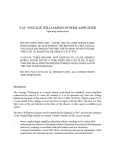
The VAC Renaissance Mk II
Master Control
Triode Preamplifier
Operation & Maintenance Information
Valve Amplification Company
Manual revised 06/22/2004
CAUTION
THE PREAMPLIFIER AND POWER SUPPLY CONTAIN NO USER SERVICEABLE PARTS. DO NOT
REMOVE THE BOTTOM PLATES OR CHASSIS COVERS. LETHAL VOLTAGES ARE PRESENT
WITHIN THE CHASSIS. DO NOT OPERATE THE UNITS IF THEY ARE WET.
VACUUM TUBES BECOME HOT ENOUGH TO CAUSE SERIOUS BURNS. NEVER TOUCH A TUBE
WHEN THE UNIT IS ON. IT MAY TAKE SEVERAL MINUTES FOR THE TUBES TO COOL DOWN
AFTER THE UNIT IS SWITCHED OFF. IT IS STRONGLY RECOMMENDED THAT THE TUBE COVERS
BE LEFT IN PLACE AT ALL TIMES.
THE GLASS COVERS WILL BECOME HOT IN NORMAL OPERATION. DO NOT SET OR SPRAY
ANYTHING ON THEM.
THE AMPLIFIER AND POWER SUPPLY ARE HEAVY. IT IS ADVISABLE TO HAVE ASSISTANCE IN
UNPACKING, MOVING, AND SETTING UP. BE SURE TO USE PROPER LIFTING TECHNIQUES TO
AVOID BACK STRAIN AND INJURY. BE CERTAIN TO INSTALL IT IN A SECURE LOCATION FROM
WHICH IT CAN NOT FALL OR TIP OVER.
CONTENTS
Introduction
Unpacking, Assembly/Disassembly
Installation
Inputs (back panel)
Outputs & Grounding Switch (back panel)
Operation
Fuses
Front Panel Controls
Remote Control
Replacement of Tubes
Care of Chassis
A Word About Tubes In General / Locating a Defective Tube
Warranty / Registration Form
1
INTRODUCTION
The Renaissance Mk II Preamplifier utilizes the world's finest audio preamplifier circuit and is
a unique component. Its unusual topology, premium parts, and flexibility make it a pleasure
to hear and operate.
The line stage is, in effect, a small Class A1 power amplifier, capable of driving loads as low
as a few hundred ohms. This is a stark contrast to normal preamplifiers, which claim a low
output impedance but completely collapse when asked to deliver current. The Renaissance
Mk II circuit is loafing with a normal load in the 10,000 to 200,000 ohm range, delivering an
effortless, musical performance.
There is no loop feedback and no coupling capacitors in the line section. All active elements
are triode tubes, the purest, most linear amplifying devices yet invented. Output matching
is accomplished by way of superb output transformers. As a side benefit, different output
grounding configurations are possible, optimizing performance into either balanced or
single-ended loads, and allowing ground loops to be broken.
The optional phono stage uses triode tubes operating without loop feedback. Gain is
moderately high, with a very low noise floor. Low output MC cartridges are accommodated
by means of high quality matching transformers, which contribute voltage gain without noise,
resulting in detail that emerges from a remarkably dark and neutral background.
Remote volume control is implemented via a motorized mechanical device. This provides
two major advantages. First, the control is completely intuitive to use. Second, we avoid the
sound degradation attendant with VCAs, transistor switches, and switched resistor arrays.
The main chassis is formed from aluminum to avoid magnetic interaction effects. The separate
power supply allows e.m.f. fields, switching transients, and mechanical vibration to be
isolated from the audio circuits.
The Renaissance Mk II is designed not to the latest fad but to substance, for the highest
possible sound quality. Time spent familiarizing yourself with this manual will be well
rewarded.
2
UNPACKING & ASSEMBLY
The Renaissance Mk II is shipped with the vacuum tubes installed.
Connect the DC cable from the power supply.
Tighten the two retaining screws.
NOTE:
Do not plug the power supply into the wall outlet unless it is connected to the
audio chassis.
Connect the iVAC data communications cable to an associated Phi Power Amplifier if
appropriate. This allows the preamplifier to control power on, power off, and logo
illumination intensity.
Alternatively, the 12 volt trigger outputs may be used to switch on/off some brands of
power amplifiers.
3
INSTALLATION
1)
Provide adequate ventilation.
2)
Do not operate on carpet or any other surface that might block air flow.
3)
The chassis will become warm in normal use.
4)
Do not allow the chassis to touch any metal parts, such as the frame of an equipment
rack. This might create a parallel ground path that could degrade the sound.
5)
Input connection is via single ended RCA jacks or XLR jacks (which can be from
balanced or unbalanced sources) - the input switch must be set appropriately or
sound quality will be compromised.
6)
Output can be on RCA or XLR jacks, and can be set for balanced or unbalanced
loads, with or without ground connection at the preamplifier. IMPORTANT: READ THE
SECTION ON "OUTPUTS & GROUNDING SWITCH". Connect line level inputs (CD, Tuner,
Tape, etc.) to the appropriate RCA input jacks on the rear panel. Note: with the
exception of Phono (when fitted), all inputs are "line level"
7)
Connect phono cables to the rear panel MM and/or MC inputs labeled "Phono" (both
may be used in the same system, as they are switched by a control on the front
panel). Connect the ground wire(s) from the turntable(s) or phono cable(s) to the
"Ground" terminal provided on the rear panel.
8)
Connect the power cables from the power supply to the preamplifier. Be sure to
insert the connector properly, and fully tighten the locking screws.
9)
Connect the input and output cables.
10)
Connect the power supply to the power source indicated on the rear panel, either
100, 120, 220, or 240 volts AC. The voltage may be select by means of the
removable selector card located underneath the fuse in the power connector; to
change, remove the card and reinstall so that the desired voltage may be read. Avoid
power conditioners that float the ground pin. ALWAYS connect power cord to
component before plugging it into an AC outlet, and make sure that unit's power
switch is set to the "off" position before making the final connection. For best
performance, try to route the power cord away from signal cables.
11)
Pay close attention to power quality, and be aware that different power cords can
alter the sound.
4
INPUTS (back panel)
Five pairs of RCA jacks accommodate unbalanced line level sources. These are labeled "IN1"
through "IN5". "IN4" and "IN5" can also accept balanced XLR signals - please set the
associated back panel switches accordingly.
If phono is not fitted, "IN6" can accept a line level signal via RCA jacks.
Note: not all sources with XLR connectors are balanced. Many are unbalanced, with pin 2
or pin 3 tied to ground. The Renaissance Mk II Preamplifier accepts such sources.
The “CINEMA” inputs accept an unbalanced line level source via RCA jacks.
One pair of RCA jacks accommodate the monitor return from a tape deck. If you do not
have a tape deck, these jacks can be used as an additional line level input.
When the phono option is specified, two phono inputs are provided for "MC" and "MM"
cartridges. The ground lead from the turntable should be connected to the binding post
located by these jacks.
OUTPUTS & GROUNDING SWITCH (back panel)
One pair of RCA jacks provide line level output to a tape recorder. The level of signal is not
adjusted by the volume control.
Two sets of RCA output jacks are provided as main outputs to power amplifiers. In addition,
two pair of XLR jacks can be used to drive a power amplifier. The “OUTPUT MODE” switch
must be set accordingly.
Note: On most examples of the Renaissance Preamplifier Mk II, the OUTPUT MODE
switch has two positions, equating to RCA and XLR. On some examples, however,
there is a third (center) position, which is, in effect, a “ground lift” setting, and which
may be tried with either RCA or XLR-balanced cabling.
Do not connect an unbalanced load with “pin 3 hot” to the XLR connectors.
5
OPERATION
Turn the "Volume" control fully counterclockwise.
Mute is automatically engaged when switching on the unit.
Allow the preamplifier to warm up for a minute before you un-mute the unit; failure to wait
can cause a transient to be sent through your power amplifier that might cause damage to
your loudspeakers.
As with all high fidelity products, the sound characteristic of the VAC changes somewhat as
it warms up. Best sound will be achieved after about 15 minutes of operation.
Any time that the Renaissance Mk II Preamplifier has not been used for a few weeks the
sound may be different. This is also normal for high resolution audio equipment. Optimum
sound should return after a few hours of operation, preferably with an audio signal.
Note that although your VAC System has been run for 48 hours at the factory, it will continue
to "break in" for approximately 150 hours. Also be aware that many components display the
need for a new break in period after being transported in unheated cargo aircraft.
FUSES
Please note that there are two fuses on the power supply.
One is located behind the clear plastic window of the power connector. For 220 or 240
volt operation, please use a ampere fuse. For 100 or 120 volt operation, the fuse should
be 4.0 amperes.
The other is in a conventional fuse holder. It should be a 0.3 ampere fuse.
If the unit is converted for operation at a voltage other than 220 volt, the fuse values must
be changed. Please consult the factory for more information.
See the INSTALLATION section for information on changing the operating voltage.
6
FRONT PANEL CONTROLS
Although most of the front panel controls (Volume, Power, Mute) are self explanatory, VAC
has outfitted this unit with several advanced features which bear further description:
Mute:
Toggles between the "Mute" and "Operate" condition. When muted, the
indicator light is illuminated.
Power:
Turns the unit off and on.
Phono:
Selects between the MM and MC inputs. Overall phono function is selected
with the main Selector switch (phono is one click counterclockwise from “1”
or one click clockwise from “6”).
The MM input provides 44 dB of gain, suitable for use with MM (moving
magnet) and many high-output MC (moving coil) cartridges. The MC input has
64 dB of gain, making it suitable for most low output cartridges. Both MM and
MC may be connected in the same system, so that in essence there are two
phono inputs.
Selector:
This switch selects between IN1 through IN6 and the PHONO inputs. Rotate
counterclockwise to move down through the inputs, clockwise to move up
through the inputs.
Volume:
Controls the output level for the PHONO input, and any line input set to the
“VAR” LEVEL mode.
Tape:
This switch selects between the signal coming from the main selector (light
out) or the signal connected to the “TAPE IN” jacks (light on).
Cinema:
This switch selects the source connected to the “CINEMA” input jacks.
Fixed:
This switch allows any input (except Phono) to be level controlled by the
VOLUME control, or to be produced at a FIXED level. To set an input to FIXED,
hold the toggle switch to the right for five seconds, until the indicator light
changes from blinking to solid illumination; hold the switch to the left to return
it to a VARIABLE VOLUME CONTROLLED mode.
In the VARIABLE mode, the Renaissance Mk II functions like a conventional
preamplifier.
The FIXED mode allows the control of volume to be determined entirely by
7
the source component. This is useful when the Renaissance Mk II is being
used as an element of a multichannel or home theater system, with the level
of all 5.1 channels being set by the player or the decoder.
Note: The Tape Monitor takes the same setting as the source input. For
example, if the SELECTOR is on input #1 and #1 is set up in a FIXED mode,
when you engage the TAPE monitor it will also be in the FIXED mode, and the
VOLUME control will not change the sound level. Conversely, if input #2 is in
the VAR mode, then the TAPE monitor will also be in the VAR mode, and the
volume control will function. Therefore, it is suggested that the input be
configured to VAR before recording and monitoring is started.
The FIXED mode may also be used with, for example, a CD player that has its
own volume control. In this way, the Renaissance Mk II’s volume control is
bypassed. Some audioRenaissance Mk IIles would consider this to be a “hot
rod” mode.
8
REMOTE CONTROL
The remote control allows for wireless adjustment of POWER, SELECTOR, TAPE MONITOR,
CINEMA, MUTE, and VOLUME.
The remote wand is powered by two "AAA" batteries. These should be of the alkaline type.
You will need to install them in the wand before using the remote. Since batteries can leak,
they should be removed from the wand if it is not going to be used for an extended period
of time.
To install or change batteries, first loosen the screw on the
back of the remote.
Loosen the battery cover.
Remove the battery cover.
Insert two AAA batteries, observing the polarity diagram
inside th battery compartment.
Reassemble the remote control by following these steps in reverse.
9
CARE OF CHASSIS
VAC chassis are machined aluminum for superior electromagnetic performance. The main
chassis is finished in a durable clear coat over color powder coat paint. The fascia is finished
in hand rubbed lacquer (similar to a fine automobile). The power supply chassis is finished
in durable textured gloss paint. Cleaning the units with a damp cloth WHILE THE AMP IS
SWITCHED OFF AND UNPLUGGED should suffice. Do not get cleaning solutions onto or into
the tube sockets.
REPLACEMENT OF TUBES
Please refer to the chart on the next page.
Before replacing tubes, all power must be turned off. Allow 15 minutes for the tubes to cool
down before removing the top glass cover - in use they become hot enough to cause
burns.
Install new tubes of the appropriate types firmly in their sockets, noting the location of holes
in the socket and pins of the tubes, taking care to make sure that pin pattern corresponds
to holes in tube socket. Replace the glass cover before operating the preamplifier.
In the event that trouble is encountered, check all signal, speaker and power connections.
If the problem persists, follow all safety precautions stated earlier in this section, and check
that all tubes are correctly seated in their sockets. If possible, try another tube. If the problem
persists, please consult your VAC dealer or contact the factory directly.
Tubes are like the tires on a car; they will eventually need replacement. Murphy's Law states
that a tube will probably fail right at the start of a long holiday weekend. Therefore, many
audiophiles keep a spare tube of each type on hand, just in case!
There is no substitute for the 8416 tube type.
We strongly recommend that you use only tubes specifically selected and tested by VAC
for this application.
VAC can test tubes for concerned customers.
10
Tube Placement
Renaissance Mk II Preamplifier
Note: disconnect all cables and wait 15 minutes before removing the top.
Reinstall the top before reconnecting any cables.
8416
8416
12AX7
Low noise
12AX7
12AX7
12AX7
Phono
Line stage
Lethal voltages exist inside the chassis. Follow all
of safety procedures and precautions detailed
in the owner’s manual when changing tubes.
11
TIPS & ADVICE SECTION
A Word About Tubes in General
It is true that each brand of tube sounds different in a particular high resolution circuit. This
is because no two manufacturers make a tube type in quite the same way, and the central
tendencies of the performance parameters will differ slightly with each maker. To emphasize
the point, examine the plate structure of any two 6SN7 from different manufacturers will
probably find that they may not even the same shape and size. (Be careful here, as often a
tube is made by a firm other than indicated on its label. In the heyday of tubes it was
common to crossbrand between major labels, such as GE and RCA. Today many labels do
not manufacture their tubes at all, including Gold Aero and RAM.)
This sonic variability may at first seem a liability, but further thought will reveal that it is an
advantage, just like the ability to adjust VTA on a tone arm. The owner of a tube amplifier can
select those tubes which sound like the real thing in his/her specific system. Of course, if the
manufacturer you prefer is rare you may want to purchase a few spare tubes for the future.
How long should tubes last? It has long been known in professional circles (and probably
now forgotten) that a tube such as the 12AX7 will display better performance characteristics
after two years of continual operation than when it was new. In normal use it is not unusual
for a low level tube to last 5 years or longer. Output tubes are another story, as they are
continually providing significant amounts of current. Here the sound is your best guide.
Certainly a tube should be replaced when its emission is significantly down or its
transconductance is substantially out of specification. In normal use, output tubes will last at
least 2 years and perhaps more than 5 years.
In the event of unusual noise in one channel, or a loss of sound in one channel, a
bad tube may be located easily. Start by exchanging V4L with V4R; if the problem
changes channels then you have found the bad tube. If not, switch V3L with V3R,
and so on, until the symptom changes channels.
VAC can test tubes for concerned customers.
12
WARRANTY
Your equipment is warranted for a period of thirty (30) days from the date of purchase. In addition, if the
registration form is received by VAC along with a copy of your sales receipt from an authorized VAC dealer
within this thirty days, a service contract will be extended to cover your equipment for three (3) years (tubes
excepted). This warranty applies only to units sold in the United States of America through authorized VAC
dealers. It covers factory service and standard return shipping. For warranty information outside of the U.S.
contact the importer of VAC equipment for your country. Units sold outside of the U.S. should still be
registered with VAC. It is responsibility of the dealer and customer to determine suitability of this unit for a
given application.
Your questions and comments are always welcome. Contact:
Valve Amplification Company
1731 Northgate Boulevard
Sarasota, FL 34234
Telephone (941) 359-2066
[email protected]
Fax (941) 359-2057
_____________________________Detach and mail to the address above as soon as possible.____________________________
Renaissance Mk II Registration Form
Name
________________________________________________________________________
Address
________________________________________________________________________
________________________________________________________________________
Telephone
_______/_______-_____________
e-mail __________________________________
Dealer name
________________________________ City ________________________________
Salesperson
___________________ Purchase date
____________ Serial Number ________________
How did you first learn of VAC products? ____________________________________________________
What other brands/models did you consider? _________________________________________________
_____________________________________________________________________________________
What made you decide on the VAC? _______________________________________________________
_____________________________________________________________________________________
What else would you like us to know? _______________________________________________________
_____________________________________________________________________________________
_____________________________________________________________________________________
Optional:
What magazines do you read regularly?________________________________________________________
What are your hobbies (besides filling in warranty cards)? _______________________________________
What are your favorite types of music? ______________________________________________________
_____________________________________________________________________________________
On what format? (CD, LP, DVD, SACD, MP3, etc.) ______________________________________________
13