1
724
OWNERS MANUAL
for
SOLUBLE
COFFEE
DISPENSERS
MODEL:
9461KFT
Includes:
Installation
Operation
Use & Care
Servicing Instructions
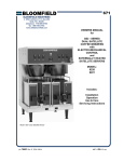
Model 9461 Dispenser
PRINTED IN UNITED STATES OF AMERICA
p/n 76948 Rev. C ECN-12743
M725
040825 cps
WARRANTY STATEMENT
It also does not apply if the serial nameplate has been
removed or unauthorized service personnel perform service.
The prices charged by Bloomfield Industries for its products
are based upon the limitations in this warranty. Seller’s
obligation under this warranty is limited to the repair of defects
without charge by a Bloomfield Industries Authorized Service
Agency or one of its sub-agencies. This service will be
provided on customer’s premises for non-portable models.
Portable models (a device with a cord and plug) must be
taken or shipped to the closest Authorized Service Agency,
transportation charges prepaid, for services.
All electrical equipment manufactured by BLOOMFIELD
INDUSTRIES is warranted against defects in materials and
workmanship for a period of one year from the date of original
installation or eighteen (18) months from the date of shipment
from our factory, whichever comes first, and is for the benefit
of the original purchaser, except that:
a. airpots carry a 30 day parts warranty only.
b. dispensers; i.e., tea and coffee carry a 90 days parts
warranty only, excludes decanters.
THE FOREGOING OBLIGATION IS EXPRESSLY GIVEN IN
LIEU OF ANY OTHER WARRANTIES, EXPRESSED OR
IMPLIED, INCLUDING ANY IMPLIED WARRANTY OF
MERCHANTABILITY OR FITNESS FOR A PARTICULAR
PURPOSE, WHICH ARE HEREBY EXCLUDED.
In addition to restrictions contained in this warranty, specific
limitations are shown below (Additional Warranty Exclusions).
Bloomfield Industries Authorized Service Agencies are located
in principal cities.
BLOOMFIELD INDUSTRIES DIVISION / SPECIALTY
EQUIPMENT MANUFACTURING CORPORATION SHALL
NOT BE LIABLE FOR INDIRECT, INCIDENTAL OR
CONSEQUENTIAL DAMAGES OR LOSSES FROM ANY
CAUSE WHATSOEVER.
This warranty is valid in the United States and void elsewhere.
Please consult your classified telephone directory or your food
service equipment dealer; or, for information and other details
concerning warranty, write to:
Service Parts Department
Bloomfield Industries
P.O. Box 280
Verdi, NV 89439
Phone: (775) 345-0444
Fax: (888) 492-2783
This warranty is void if it is determined that upon inspection by
an Authorized Service Agency that the equipment has been
modified, misused, misapplied, improperly installed, or
damaged in transit or by fire, flood or act of God.
SERVICE POLICY AND PROCEDURE GUIDE
ADDITIONAL WARRANTY EXCLUSIONS
1.
2.
3.
4.
5.
6.
7. Full use, care and maintenance instructions are supplied
with each machine. Those miscellaneous adjustments
noted are customer responsibility. Proper attention will
prolong the life of the machine.
8. Travel mileage is limited to sixty (60) miles from an
authorized Service Agency or one of its sub-agencies.
9. All labor shall be performed during normal working hours.
Overtime premium shall be charged to the customer.
10. All genuine Bloomfield replacement parts are warranted
for ninety (90) days from date of purchase on nonwarranted equipment.
Any use of non-genuine
Bloomfield parts completely voids any warranty.
11. Installation, labor and job check-out are not considered
warranty.
12. Charges incurred by delays, waiting time or operating
restrictions that hinder the service technicians ability
to perform services are not covered by warranty.
This includes institutional and correctional facilities.
Resetting of safety thermostats, circuit breakers,
overload protectors, or fuse replacements unless
warranted conditions are the cause.
All problems due to operation at voltages other than
specified on equipment nameplates; conversion to
correct voltage must be the customer’s responsibility.
All problems due to electrical connections not made in
accordance with electrical code requirements and
wiring diagrams supplied with the equipment.
Replacement of items subject to normal wear, to include
such items as knobs and light bulbs. Normal maintenance
functions including adjustment of thermostats, microswitches,
and replacement of fuses and indicating lights are not
covered under warranty.
All problems due to inadequate water supply, such as
fluctuating, or high or low water pressure.
All problems due to mineral/calcium deposits, or
contamination from chlorides/chlorines. De-liming is
considered a preventative maintenance function and is
not covered by warranty.
SHIPPING DAMAGE CLAIMS PROCEDURE
NOTE: For your protection, please note that equipment in
this shipment was carefully inspected and packaged by
skilled personnel before leaving the factory.
Upon acceptance of this shipment, the transportation
company assumes full responsibility for its safe delivery.
IF SHIPMENT ARRIVES DAMAGED:
1. VISIBLE LOSS OR DAMAGE: Be certain that any
visible loss or damage is noted on the freight bill
or express receipt, and that the note of loss or damage
is signed by the delivery person.
2. FILE CLAIM FOR DAMAGE IMMEDIATELY:
Regardless of the extent of the damage.
3.
CONCEALED LOSS OR DAMAGE: if damage is
unnoticed until the merchandise is unpacked, notify the
transportation company or carrier immediately, and file
“CONCEALED DAMAGE” claim with them. This
must be done within fifteen (15) days from the date the
delivery was made to you. Be sure to retain the
container for inspection.
Bloomfield Industries cannot assume liability for damage or
loss incurred in transit. We will, however, at your request,
supply you with the necessary documents to support your
claim.
xi
TABLE OF CONTENTS
WARRANTY STATEMENT
SPECIFICATIONS
FEATURES & OPERATING CONTROLS
PRECAUTIONS & GENERAL INFORMATION
AGENCY LISTING INFORMATION
INSTALLATION INSTRUCTIONS
OPERATION - DISPENSING COFFEE
CLEANING INSTRUCTIONS
TROUBLESHOOTING SUGGESTIONS
SERVICING INSTRUCTIONS
Deliming Instructions
EXPLODED VIEW & PARTS LIST
WIRING DIAGRAM
xi
1
2
3
3
4
7
8
11
12
15
16
20
Thank You for purchasing this
Bloomfield Industries appliance.
Proper installation, professional
operation and consistent
maintenance of this appliance will
ensure that it gives you the very
best performance and a long,
economical service life.
This manual contains the
information needed to properly
install this appliance, and to use,
care for and maintain or repair the
appliance in a manner which will
ensure its optimum performance.
SPECIFICATIONS
MODEL
9461KFT
STYLE
Soluble Coffee
Dispenser
VOLTS
50/60 Hz 1ø
WATTS
AMPS
POWER SUPPLY
REQUIRED
120 VAC
1700
14.2
NEMA 5-15P
APPLICABILITY
This manual applies to the following Bloomfield Industries products:
Model 9461KFT 120V Soluble Coffee Dispenser
1
FEATURES AND OPERATING CONTROLS
Fig. 1 Features & Operating Controls
ITEM
DESCRIPTION
ITEM
DESCRIPTION
1
DOOR ASSEMBLY
23
PRODUCT CANISTERS (2 ea.)
1-9
ILLUMINATED TRANSLIGHT
24
CANISTER SHELF
4
"COFFEE" DISPENSE SWITCH
25
WATER DISPENSE ADAPTER (3 ea.)
5
"DECAF" DISPENSE SWITCH
26
DISPENSING NOZZLE (3 ea.)
6
"HOT WATER" DISPENSE SWITCH
28
UPPER MIXING CHAMBER (2 ea.)
12
POWER CORD NEMA 5-15P 120V 15A
29
LOWER MIXING CHAMBER (2 ea.)
13
HEATER ON/OFF SWITCH
30
POWDER DISPENSING ELBOW (2 ea.)
16
HOT WATER DISPENSE TUBE
35
FLIP-DOWN CUP GRID
17
ADJUSTABLE LEGS (4 ea.)
38
REMOVABLE DRAIN GRID
18
(R) POWER ON INDICATOR LIGHT
47
AUGER DRIVE (2 ea.)
(L) READY INDICATOR LIGHT
48
DRIP TRAY ASSEMBLY
19a
(TOP) SOLENOID ON/OFF SWITCH
52
REAR ACCESS PANEL
19b
(BOT) SERVE/SANITIZE SWITCH
58
POWER ON/OFF SWITCH
2
PRECAUTIONS AND GENERAL INFORMATION
WARNING: Electric Shock Hazard
All servicing requiring access to non-insulated components must be performed by qualified
service personnel. Do not open any access panels which require the use of tools. Failure to
heed this warning can result in electrical shock.
WARNING: Injury Hazard
All installation procedures must be performed by qualified personnel with full knowledge of all
applicable electrical and plumbing codes. Failure could result in property damage and
personal injury.
WARNING Electric Shock Hazard
Appliance must be properly grounded to prevent possible shock hazard. DO NOT assume a
plumbing line will provide such a ground. Electrical shock will cause death or serious Injury.
WARNING: Burn Hazard
This appliance dispenses very hot liquid. Serious bodily injury from scalding can occur from
contact with dispensed liquids.
This appliance is intended for commercial use only.
This appliance is intended for use to dispense beverage
products for human consumption. No other use is recommended
or authorized by the manufacturer or its agents.
This appliance is intended for use in commercial establishments,
where all operators are familiar with the appliance use,
limitations and associated hazards. Operating instructions and
warnings must be read and understood by all operators and
users.
CAUTION: Equipment
Electrical Damage
DO NOT plug in or energize this
appliance until all Installation
Instructions are read and followed.
Damage to the Brewer will occur if
these instructions are not followed.
CAUTION:
Burn Hazard
Except as noted, this piece of equipment is made in the USA and
has American sizes on hardware. All metric conversions are
Exposed surfaces of the appliance
approximate and can vary in size.
and any container used to hold the
The following trouble shooting, component views and parts lists
dispensed liquid may be HOT to
are included for general reference, and are intended for use by
the touch, and can cause serious
qualified service personnel.
burns.
This manual should be considered a permanent part of this
appliance. The manual must remain with the appliance if it is
sold or moved to another location.
AGENCY LISTING INFORMATION
This dispenser is
This dispenser meets
and
listed under UL file E9253.
Standard 4 only when installed,
E9253
operated and maintained in accordance with the enclosed
instructions.
STD 4
3
E9253
INSTALLATION
READ THIS CAREFULLY BEFORE STARTING THE INSTALLATION
CAUTION
EQUIPMENT
ELECTRIC DAMAGE
DO NOT plug in or energize this
appliance until all Installation
Instructions are read and
followed. Damage to the
Brewer will occur if these
instructions are not followed.
CAUTION
UNSTABLE
EQUIPMENT HAZARD
It is very important for safety
and for proper operation that the
appliance is level and stable
when standing in its final
operating position. Provided
adjustable legs must be
installed at each corner of the
unit. Failure to do so will result
in movement of the dispenser
which can cause personal Injury
and/or damage to brewer.
NOTE: Water supply inlet line
must meet certain minimum
criteria to insure successful
operation of the dispenser.
Bloomfield recommends 1/4"
copper tubing for installation of
less than 12 feet and 3/8" for
more than 12 feet from a 1/2"
water supply line.
Unpack the unit. Inspect all components for completeness and
condition. Ensure that all packing materials have been removed
from the unit.
LEVELING THE UNIT
Verify that an adjustable leg is installed at each corner of the
dispenser.
Set dispenser in its operating location. Level the dispenser. A
spirit level should be placed on the top of the unit, at the edge,
as a guide when making level adjustments.
Level the unit from left to right and front to back by turning the
adjustable feet. Be sure all four feet touch the counter to prevent
tipping.
PLUMBER’S INSTALLATION INSTRUCTIONS
Dispenser should be connected to a POTABLE WATER, COLD
WATER line. Flush water line before connecting to dispenser.
DO NOT use a saddle valve with a self-piercing tap for the water
line connection. Such a tap can become restricted by waterline
debris. For systems that must use a saddle tap, shut off the main
water supply and drill a 3/16” (minimum) tap for the saddle
connection, in order to insure an ample water supply. Remember
to flush the line prior to installing the saddle.
The dispenser must be installed on a water line with average
pressure between 20 PSI and 90 PSI. If your water pressure
exceeds 90 PSI at anytime, a pressure regulator must be
installed in the water supply line to limit the pressure to not more
than 90 PSI in order to avoid damage to lines and solenoid.
A water shut-off valve should be installed on the incoming water
line in a convenient location (Use a low restriction type valve,
such as a 1/4-turn ball valve, to avoid loss of water flow thru the
valve.
Model 9461KFT requires a 1/4" female flare fitting to connect to
the water inlet fitting on the bottom of the unit.
4
INSTALLATION (continued)
NSF requires 4" legs for cleaning underneath unit. A flex line or
loops of copper tubing from water supply should be used if the
unit will be moved. See Figure 2 below.
Fig. 2a Water Supply Installation - Cold Water
Fig. 2b Water Supply Installation - Hot Water
The DRIP TRAY pan is equipped with a drain outlet.
Bloomfield recommends that this drain outlet be connected to
1/2" I.D. flexible tubing and routed to a building drain. If a drain
line is not used, the supplied plug on the pan drain fitting must
remain in place.
Fig. 3 Drain Line Connection
5
NOTE: This equipment must
be installed to comply with all
applicable federal, state and
local plumbing codes and
ordinances.
INSTALLATION (continued)
IMPORTANT:
The ground prong of the plug is
part of a system designed to
protect you from electrical shock
in the event of internal damage.
Never cut off the ground prong
nor twist a blade to fit an
existing receptacle. Contact a
licensed electrician to install the
proper circuit and receptacle.
GROUND
PIN
ELECTRICIAN’S INSTALLATION INSTRUCTIONS
REFER TO ELECTRICAL SPECIFICATIONS - Page 1
Check the nameplate to determine correct electrical service
required for the dispenser to be installed.
IMPORTANT: Before connecting to electricity, make sure the
dispenser is connected to the water supply.
Model 9461KFT requires a dedicated 120 volt single phase
15 amp circuit connected to a properly grounded NEMA 5-15R
receptacle.
STARTUP
NEMA 5-15P
PLUG
NEMA 5-15R
RECEPTACLE
Fig 4. Power Connection
IMPORTANT:
Connecting the unit to the
wrong voltage will damage the
dispenser or result in decreased
performance. Such damage is
not covered by warranty.
Be sure the HEATER ON/OFF SWITCH (item 13) is OFF, then
connect appliance to electric power. Press the POWER ON/OFF
SWITCH (item 58) to the ON position. POWER ON light will glow.
The tank will begin filling. When the tank is full, press the
HEATER ON/OFF SWITCH and SOLENOID ON/OFF SWITCH
to ON. The elements will be energized and the tank will begin
to heat. When the water has reached proper dispensing
temperature, the READY light will glow.
Do not install product canisters yet. Place a container under a
dispense nozzle and flow water until all air is purged from the
valves and lines. Repeat for each of the three nozzles.
Be sure drip pan/drip tray is properly assembled and installed.
IMPORTANT: Do not connect
dispenser to electrical power
until you are ready to fill the
tank. See instructions at left.
INITIAL ADJUSTMENTS
Tank temperature thermostat is factory set at 198ºF. If a lower
temperature is necessary:
Remove cabinet top panel. Thermostat on right controls tank
temperature. To lower temperature setting, turn stem counterclockwise.
6
OPERATION - DISPENSING COFFEE
PREPARATION
CAUTION
Press the SOLENOID ON/OFF SWITCH to ON.
Press the SERVE/SANITIZE switch to SERVE.
Fill PRODUCT CANISTERS with the appropriate product.
Left (large canister) - Regular Coffee
Right (small canister) - Decaf Coffee
Install PRODUCT CANISTERS on the CANISTER SHELF.
The AUGER DRIVE must engage the AUGER COUPLING.
Turn POWDER DISPENSE ELBOWS DOWN, so that they are
centered in the opening of the UPPER MIXING CHAMBERS.
Burn Hazard
Dispense nozzles may be
HOT to the touch, and can
cause serious burns.
CAUTION
Burn Hazard
To avoid splashing or
overflowing hot liquids,
ALWAYS place an empty
container under the
dispense nozzle before
pulling the dispense
handle. Failure to comply
can cause serious burns.
IMPORTANT:
Coffee will continue to flow
for several seconds after
the dispense handle is
released.
DO NOT remove the
container until all flow
has stopped.
Fig. 5 Dispensing System Assembly
SERVING
Place an appropriate container under the DISPENSE NOZZLE.
Use the POSITIONING BRACKET to accurately position the
container.
If the NOT READY light is lit, water temperature is too low for
dispensing. Wait until the NOT READY light goes off.
Pull the handle of the DISPENSE SWITCH until the product in the
container is near the desired level, then release the handle.
DO NOT remove the container for several seconds after
releasing the handle. Water in the mixing chamber will require this
time to drip out as coffee.
7
NOTE: Should WATER
VOLUME adjustment be
required:
See page 12 for
adjustment instructions.
Turn adjustment screw
CLOCKWISE to decrease
water flow;
COUNTERCLOCKWISE to
increase water flow.
CLEANING INSTRUCTIONS
CAUTION
BURN HAZARD
PROCEDURE: Clean Coffee Dispenser
PRECAUTIONS: None
Dispensing and serving
temperatures of coffee are
extremely hot.
Hot coffee will cause
serious skin burns.
CAUTION
ELECTRIC SHOCK
HAZARD
FREQUENCY:
Daily
TOOLS:
None Required
1. Press the SERVE/SANITIZE SWITCH to SANITIZE.
2. Place an empty 1/2 gallon container under the "COFFEE"
dispense nozzle. Pull the "COFFEE" dispense handle for
15 seconds. Discard all water generated.
3. Repeat for the "DECAF" dispenser.
DO NOT pour or splash water
into any controls or wiring.
IMPORTANT:
DO NOT use steel wool, sharp
objects, or caustic, abrasive or
chlorinated cleansers to clean
the dispenser or components.
4. Visually inspect UPPER and LOWER MIXING CHAMBERS
for condition and proper assembly.
5. Visually inspect PRODUCT CANISTERS for condition.
Refill as necessary.
6. Press the SERVE/SANITIZE SWITCH to SERVE.
7. Close all panels.
Procedure is complete
8
CLEANING INSTRUCTIONS (continued)
PROCEDURE: Clean Coffee Dispenser
PRECAUTIONS: Disconnect dispenser from electric power.
Allow dispenser to cool.
FREQUENCY:
Weekly
TOOLS:
Mild Detergent, Clean Soft Cloth or Sponge
Soft Bristle Brush, Bottle Brush
1.
Disconnect dispenser from electric power.
Allow dispenser to cool.
CAUTION
BURN HAZARD
Dispensing and serving
temperatures of coffee are
extremely hot.
Hot coffee will cause
serious skin burns.
CAUTION
2. Remove PRODUCT CANISTERS and DRIP TRAY.
3. Remove DISPENSING NOZZLES by turning 1/4 turn and
pulling straight down.
4. Remove UPPER and LOWER MIXING CHAMBERS.
Disassemble into separate components.
5. Wash nozzles and mixing chamber components in warm
water with mild detergent. Use appropriate soft brushes to
clean caked-on product.
6. Rinse mixing components with clear water. Drain thoroughly
and allow to air dry.
ELECTRIC SHOCK
HAZARD
Do not submerge or immerse
dispenser in water.
DO NOT pour or splash water
into any controls or wiring.
IMPORTANT:
DO NOT use steel wool, sharp
objects, or caustic, abrasive or
chlorinated cleansers to clean
the dispenser or components.
7. Empty and clean product canisters (See page 10).
8. Empty and clean DRIP TRAY.
9. Clean DRAIN PAN:
a. If not plumbed to drain, remove, empty and rinse with
clear water. Allow to dry, then reinstall.
b. If plumbed to drain, scrub with a mild detergent solution
and a soft bristle brush. Rinse with clear water.
10. Remove CANISTER SHELF. Wipe VACUUM CHAMBER
and underside of shelf. Reinstall shelf.
11. Wipe interior and exterior of dispenser with a clean cloth
dampened with warm water and mild detergent. Rinse with a
clean cloth dampened with warm water. Be sure to clean
mixing chamber area behind dispense switches thoroughly.
IMPORTANT: DO NOT allow water to drip or spill into any
controls or wiring.
12. Reassemble:
Verify that TANK HEAT SWITCH is ON, SOLENOID OFF
ON SWITCH is ON, and that SERVE/SANITIZE SWITCH is
in the SERVE position.
Reinstall DISPENSE NOZZLES.
Reinstall UPPER and LOWER MIXING CHAMBERS.
Reinstall PRODUCT CANISTERS and DRIP TRAY.
Close all panels and reconnect dispenser to electric power.
Mixing Components
Assembly Diagram
Procedure is complete
9
CLEANING INSTRUCTIONS (continued)
PROCEDURE: Clean Product Canisters
CAUTION
BURN HAZARD
PRECAUTIONS: None
FREQUENCY:
Monthly
TOOLS:
Mild Detergent, Clean Soft Cloth or Sponge
Soft Bristle Brush, Bottle Brush
Brewing and serving
temperatures of coffee are
extremely hot.
Hot coffee will cause
serious skin burns.
1. Remove CANISTERS from dispenser.
2. Remove CANISTER LIDS and empty all product from
CANISTERS.
3. Disassemble AUGER from canister.
NOTE: While the AGITATOR wheel and spring assembly
may be removed from the canister, Bloomfield recommends
that it be removed only if necessary for repair.
4. Wash canister components in warm water with mild
detergent. Use appropriate soft brushes to clean caked-on
product.
5. Rinse canister components with clear water. Drain
thoroughly and allow to air dry.
6. Reassemble CANISTERS.
7. Install POWDER DISPENSE ELBOWS on canisters.
Fill PRODUCT CANISTERS with the appropriate product.
Left hopper - Regular Coffee
Right hopper - Decaf Coffee
Reinstall CANISTERS LIDS
8. Install PRODUCT CANISTERS on the CANISTER SHELF.
The AUGER DRIVE must engage the AUGER COUPLING.
Procedure is complete
10
IMPORTANT:
DO NOT use steel wool, sharp
objects, or caustic, abrasive or
chlorinated cleansers to clean
the dispenser or components.
IMPORTANT:
Left and right canisters use
identical internal components.
Use care to reassemble
components in the proper order
and position so that "COFFEE"
mounts to the left and "DECAF"
mounts to the right.
TROUBLESHOOTING SUGGESTIONS
SYMPTOM
POSSIBLE CAUSE
SUGGESTED REMEDY
No power to brewer
Power switch off
Turn power switch on
Circuit breaker off or tripped
Reset circuit breaker
Hi-limit tripped
Allow to cool, reset hi-limit
Tank heat switch off
Turn tank heat switch on
Heating thermostat set too low
Set to desired temperature
Damaged element(s)
Replace element(s)
Damaged thermostat
Replace heating thermostat
Damaged contactor
Replace contactor
Power switch off
Turn power switch on
Water supply off
Reestablish water supply
Inlet solenoid screen plugged
Clean solenoid screen
Water level probe damaged
Replace probe
Water level board damaged
Replace water level board
Inlet solenoid damaged
Replace solenoid
Power light damaged
Replace power light
Water not heating
Tank does not fill
Power light does not come on
Not ready light does not go off
Dispense thermostat set too high Set to desired temperature
(water is at desired temperature)
No product dispensed
Canister empty
Refill canister
Serve/sanitize switch in sanitize
Set switch to serve
Hopper improperly assembled or Reassemble or replace hopper
damaged
Speed control not properly set or Adjust or replace speed control
damaged
Auger motor damaged
Replace auger motor
No water dispensed
(both coffee and decaf)
Solenoid switch off
Set switch to on
No water dispensed
(any one dispenser)
Damaged brew solenoid
Replace brew solenoid
No product or water dispensed
Damaged dispense switch
Replace dispense switch
Product clumps instead of mixing Mixing assembly mis-assembled Assemble properly
Hopper shelf misassembled
Properly install shelf
Vacuum system clogged
Clean vacuum blower, chamber
and tubing
MUST BE
PERFORMED BY QUALIFIED
TECHNICIAN ONLY!
Vacuum blower damaged
Replace vacuum blower
NOTE: Always check wiring for damage and tight connections.
11
SERVICING INSTRUCTIONS
PROCEDURE: Adjust Water Volume
PRECAUTIONS: Disconnect brewer from electric power.
Allow brewer to cool.
FREQUENCY:
As required (water volume is too high or low,
or as required for coffee taste)
TOOLS:
Flat Blade Screwdriver
#2 Phillips Screwdriver
1. Carefully remove product canisters. Place an appropriate
container in position under the dispense nozzles.
2. Carefully remove panel #33 to access water valves. Position
panel out of the way. Be careful not to damage fan or
connecting wires attached to panel.
3. Set the SERVE/SANITIZE SWITCH to SANITIZE.
4. Pull and hold a dispense handle, then turn associated water
valve adjustment screw until the desired level in the mixing
chamber is achieved.
Turn COUNTERCLOCKWISE to increase flow
Turn CLOCKWISE to decrease flow.
5. Pull individual dispense handles several times to verify new
flow settings.
6. Replace rear panel. Set SERVE/SANITIZE SWITCH to
SERVE, then reinstall product canisters.
Procedure is complete
12
SERVICING INSTRUCTIONS (continued)
NOTE; Adjust water volume
(see page 12) before adjusting
mixture.
PROCEDURE: Adjust Mixture
PRECAUTIONS:
None:
FREQUENCY:
Initial Setup, or as required
TOOLS:
Water volume calibrated in fluid ounces
Scale calibrated in grams
Stopwatch
Container to collect dispensed powder
1. Place a volume measure under the "COFFEE" dispense
nozzle.
2. Set the SERVE/SANITIZE SWITCH to SANITIZE. This
allows water to be dispensed without activating the auger
motor.
3. With an accurate stopwatch, time how long the dispense
handle must be held in order to deliver ten ounces to the
volume measure. Note this time. Return the SERVE/
SANITIZE SWITCH to SERVE.
4. Calibrate the scale for the tare weight of the container to be
used to collect the powder.
5. Thoroughly dry all components of the "COFFEE" mixing
assembly.
6. Set SOLENOID SWITCH to OFF. This allows the auger
motor to run without dispensing water.
7. Activate the dispense for an amount of time noted in step 3.
8. Weigh the dispensed powder. The recommended ratio is:
0.25 grams of powder per fluid ounce of water. The auger
should deliver exactly 2.5 grams of powder in the time
noted in step 3.
9. If necessary, adjust the LEFT AUGER SPEED CONTROL on
the SPEED CONTROL BOARD. Turn clockwise to increase
delivered weight of powder, counterclockwise to decrease.
10. Repeat procedure for "DECAF" side.
11. Return SERVE/SANITIZE to SERVE and SOLENOID ON/
OFF SWITCH to ON.
Procedure is complete
13
Recommended ratio is:
0.25 grams of powder
fluid ounce of water.
From this setting, weight of
delivered powder may be
adjusted to taste with the
AUGER SPEED CONTROLS.
NOTE: Speed control position 4
will deliver approximately .25
grams per ounce
SERVICING INSTRUCTIONS (continued)
CAUTION -
PROCEDURE: Program Portion Control
ELECTRIC SHOCK
HAZARD
PRECAUTIONS: Possible exposed electrical circuits
Panels removed for this
procedure may expose live
electrical circuits. Use due
caution around wiring and
connectors.
FREQUENCY:
When needed
TOOLS:
#2 Phillips Screwdriver
Small pointed stylus (or ballpoint pen)
Switch #1, #2, or #3 can be
turned ON to enable portion
control for that dispensing
nozzle.
#1 - COFFEE
#2 - HOT WATER
#3 - DECAF
1. Turn dispenser power switch OFF.
To return to manual dispensing:
1. Turn power switch OFF.
2. Remove drip tray and
splash shield.
3. Move switch for desired
position to OFF.
4. Reinstall Splash Shield and
Drip Tray. Turn dispenser
power switch ON.
2. Remove drip pan and splash shield to access portion control
board.
3. Enable adjustment program by moving switch #4 to ON.
To adjust “coffee” portion control, move switch #1 to ON.
To adjust “hot water” portion control, move switch #2 to ON.
To adjust “decaf” portion control, move switch #3 to ON.
4. Turn dispenser power switch ON.
5. Place an empty container under the nozzle of the valve to
be set. Pull the handle to start product flow. When the
desired volume is reached, release the handle to stop the
flow and enter this volume into memory. This process may
be repeated any number of times until the exact desired
volume is achieved.
6. Repeat for all valves to be set.
7. Turn dispenser power switch OFF.
8. Move switch #4 to OFF. Leave switches #1, #2 and/or #3 in
the ON position if portion control is desired for that dispenser.
9. Reinstall Splash Shield and Drip Tray. Turn dispenser power
switch ON.
Procedure is complete
14
SERVICING INSTRUCTIONS (continued)
PROCEDURE: Delime the Water Tank
PRECAUTIONS: Disconnect dispenser from electric power.
Allow brewer to cool.
FREQUENCY:
As required (dispenser slow to heat)
TOOLS:
Deliming Solution
Protective Gloves, Goggles & Apron
Mild Detergent, Clean Soft Cloth or Sponge
Bristle Brush, Bottle Brush
Large Sink (or other appropriate work area)
1. Disconnect dispenser from electric power. Turn off the water
shut-off valve.
2. Remove the tank lid assembly.
3. Mix 8 quarts of deliming solution according to the
manufacturer’s directions. Carefully pour the deliming
solution into the water tank. Lower the lid assembly back
onto the tank. Allow to sit for 30 minutes, or as directed by
the manufacturer.
4. At end of soaking period, open the drain assembly and drain
solution from tank into an appropriate contain for disposal.
5. Remove lid assembly from tank. Thoroughly rinse internal
components of lid assembly with clear water. Using a stiff
bristle brush, scrub the heating element to remove lime and
calcium build-up. Rinse with clean water. Store lid assembly
in a safe location.
6. Using a stiff bristle brush, scrub the interior of the water tank
to remove lime and calcium build-up. Rinse with clean water
and drain.
7. Reinstall tank lid assembly. Verify that all internal
components of the dispenser are dry, then reinstall the top
panel.
8. Reconnect dispenser to electrical supply and reconnect water
supply.
9. Place the SERVE/SANITIZE SWITCH in SANITIZE position.
Run at least one gallon through each dispense nozzle and
discard all water generated.
10. Verify that TANK HEAT SWITCH is ON, and that
SERVE/SANITIZE is in the SERVE position and the
SOLENOID SWITCHES is ON. Close all panels.
Procedure is complete
15
CAUTION CHEMICAL BURN
HAZARD
Deliming chemicals are caustic.
Wear appropriate protective
gloves and goggles during this
procedure.
Never siphon deliming
chemicals or solutions by
mouth.
This operation should only be
performed by qualified and experienced service personnel.
IMPORTANT: DO NOT spill,
splash or pour water or deliming
solution into or over any internal
component other than the inside
of the water tank.
IMPORTANT: DO NOT allow
any internal wiring components
to come into contact with the
deliming solution. Take care to
keep all internal components
dry.
NOTE: Repeat steps 4 thru 6
as required to remove all scale
and lime build-up.
NOTE: Normally, silicone
hoses do not need to be
delimed. Should deliming
hoses become necessary,
Bloomfield recommends
replacing the hoses.
EXPLODED VIEW & PARTS LIST
9461 SOLUBLE COFFEE DISPENSER
16
EXPLODED VIEW & PARTS LIST (continued)
17
EXPLODED VIEW & PARTS LIST (continued)
TANK ASSEMBLY
18
EXPLODED VIEW & PARTS LIST (continued)
DISPENSE SWITCH ASSEMBLY
DOOR ASSEMBLY
WATER INLET SOLENOID
19
WIRING DIAGRAM
9461KFT
20
NOTES
21
Bloomfield Industries, Inc.
Division of Carrier Commercial Refrigeration
In US and Canada
Telephone: 775-698-5700
Fax:
888-492-2783
Fax:
800-356-5142 (for orders only)
website: www.wellsbloomfield.com
PRINTED IN UNITED STATES OF AMERICA