1
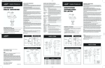
Read this before you start…
TOOLS needed for installation:
• Cutting knife
• Channel lock
• Nut driver
• Level
• Crescent wrench
• Screwdriver-flatblade
Proper installation is the responsibility of the purchaser.
SERVICE CALLS PERFORMED AS A RESULT OF POOR INSTALLATION ARE THE
RESPONSIBILITY OF THE INSTALLER.
Make sure you have everything necessary for proper installation.
3
1
5
4
2
1
GROUNDED ELECTRICAL OUTLET is required. See Electrical Requirements.
2
STANDPIPE DRAIN SYSTEM must be able to accept 1 1/2” O.D. drain hose. Standpipe
height of 36” is recommended.
NOTE: Unit is designed to pump efficiently to a height of 8 feet at normal spin speeds.
3
HOT AND COLD WATER FAUCETS must be within 4 feet of the back of the washer.
4
LAUNDRY TUB DRAIN SYSTEMS (for use with Water-Saver Models only). Tub capacity
to hold a minimum of 21 gallons.
5
WATER HEATER set to deliver 140°F (60°C) hot water to the washer.
6
PROTECTION FROM WEATHER: Do not store or operate washer below 60°F (15°C).
PARTS supplied for installation:
• 2 inlet hoses
• 4 hose washers
• 2 hose screens
• 1 cable tie
• Literature package
INSTALLATION ACCESSORY KITS
Part No.
Description
Application
12001875
Grounding Kit
Additional grounding if required by local codes.
12001585
Drain Hose Extension
Extends drain hose for drain facilities higher than 4 ft.
12001586
Anti-Siphon
Used when an air-tight connection exists between
drain hose and drain facility. Floor drain facilities.
12001599
Small Diameter Standpipe
Drain Hose
Used when standpipe diameter is too small to
receive end of drain hose.
211692
Non-Slip Disc
For painted / sloped basement floors.
204986
Carpet Installation Disc
For carpeted floors.
AUTOMATIC WASHER
INSTALLATION INSTRUCTIONS
LEAVE INSTALLATION INSTRUCTIONS AND
USER’S GUIDE WITH THE OWNER
6 2305670
Printed in U.S.A.
REQUIREMENTS
GROUNDING
ELECTRICAL
120 Volt 60 Hz
15 AMP Fuse
Individual branch circuit serving only the
washer is recommended.
The washer is equipped with a power cord.
NEVER USE AN EXTENSION CORD.
ELECTRICAL GROUND IS REQUIRED ON
THIS APPLIANCE.
Appliance is equipped with a power cord
having a 3-prong grounding plug for use in a
properly installed and grounded outlet.
Additional Ground Procedure (where local
codes permit):
It is recommended an additional ground be
installed. A proper external ground MUST
be determined prior to wire hookup.
Consult local building officials and qualified
electrician if in doubt.
For additional grounding a grounding kit
(Part No. 12001875) containing accessory
ground wire, clamp, ground screw and
washer can be purchased. Contact your
authorized Maytag dealer for further
assistance. Follow ALL grounding requirements and codes.
EXPORT MODELS – 50 HZ AND 60 HZ
A washer must be used on the voltage and frequency it was designed for. It should be operated on an individual branch circuit and fused
by no less than a 15 amp fuse or circuit breaker for 120 volt units or 10 amp fuse or circuit
breaker on 220–240 volt units. Export models
may require the addition of a plug on the
power cord. It is the responsibility of the
installer to assure that this has been done
properly. Check the data plate to be sure of
voltage and line frequency requirements.
EXPORT–specific grounding instructions must
be determined due to variation of electrical
services.
WATER
Water pressure of 20 to 120 p.s.i. is required
to correctly fill the washer to the proper levels.
Pressures of less than 20 p.s.i. may cause a
failure to the water valve. The valve might not
shut off completely.
TO AVOID THE POSSIBILITY OF WATER
DAMAGE, SHOULD A HOSE LEAK,
ALWAYS HAVE FAUCETS ACCESSIBLE
AND TURN OFF FAUCETS WHEN WASHER
IS NOT IN USE.
CABINET DIMENSIONS
26 3/4”
68.0 cm
36”
91.4 cm
36”
91.4 cm
43”
110.8 cm
51”
129.5 cm
25”
64.8 cm
SIDE VIEW
BACK VIEW
DRAIN FACILITY
FLOORING
Recommended height of standpipe is 36”. If
the standpipe is less than 36” high, the drain
hose should be routed through the clip to raise
the hose to the proper height. The standpipe
must be large enough to accept a 1 1/2”
outside diameter drain hose.
For best performance the washer must be
installed on a solidly constructed floor. Wood
floors may need to be reinforced to minimize
vibration and/or unbalanced load situations.
Carpeting and soft tile surfaces are also
contributing factors in vibration and/or
tendency for a washer to move slightly during
spin cycle. Never install washer on a platform
or weak supported structure.
Without the 36” high elevation, water may
run out of the washer prematurely. A
possible sign that the drain hose has not been
elevated to proper height is if the washer fills
and drains at the same time.
The drain hose is attached at factory. (See
Installation Accessory Kits table.)
WATER SAVER MODELS
The diverter valve is located in the lower lefthand corner on the backside of the washer.
The suds hose (hose with long gooseneck)
connects to the top diverter valve outlet. The
other end of the hose is cut at an angle to
prevent sediment from returning to the washer.
Place suds hose into a 21 gallon minimum
capacity storage tank. This hose must be in a
straight line to the storage tank and be able to
reach the bottom of the tank. Secure the hose
to the tank to prevent the hose from coming
out.
The drain hose is connected to the bottom
diverter valve outlet. The other end goes into
the standpipe. If the standpipe is less than 36”
high, the drain hose should be routed through
the clip to raise the hose to the proper height.
If the drain hose needs to be extended to
reach the drain facility, attach the extension
hose section to the siphon break using a
coupler.
LOCATION CONSIDERATIONS
It is recommended the washer never be
installed in areas where water may freeze,
since the washer will always maintain some
water in the water valve, pump and hose
areas. This can cause damage to belts, pump,
hoses and other components. Operating
temperature should be above 60°F.
COLD WEATHER STORAGE
The following precautions should be taken if a
washer is to be stored where it would be
subject to freezing conditions.
1. Turn off the water supply, remove and drain
inlet hoses.
2. Select a fill cycle and energize the water
valve by selecting a warm water setting. A
few seconds of fill is sufficient.
3. Disconnect from electrical supply.
4. Use flat blade screwdriver to release two
clips at bottom corners of front panel.
Remove front panel.
5. Remove the hose clamps and drain the
water from the drain hose and pump by
lowering the drain hose to floor level.
Do not extend gooseneck end or cut gooseneck end off. Be sure each section of hose is
securely pushed over the ends of the coupler
and should join at approximately the middle of
the coupler.
Now with the drain hose elevated 36”, it can
go into a floor drain or low standpipe.
STEP 1
STEP 5
• Remove all items from inside of wash tub.
• Replace tub block and tape lid shut.
• Remember! After installation is completed,
the tub block needs to be removed.
Run water through both water faucets into a
bucket to purge the water line particles that
might clog the hoses. While running water
through the faucets, determine which faucet is
HOT water and place an identifying mark on it.
Traditionally the HOT water faucet is on the
STEP 2
• Lay two carton corner posts on the floor.
• Make sure one corner post is placed against
the wooden crate bottom.
• Tip washer forward on its front so it will lay
across both corner posts.
STEP 6
Insert one screen and then one washer into
the faucet ends of the inlet hoses. The
screens should be pointing out to fit properly.
STEP 3
• Remove crate wires and crate base.
STEP 7
Attach the inlet hoses to the HOT and COLD
faucets. Being sure the hose marked “HOT” is
attached to the HOT water faucet. Tighten by
hand until snug and then 2/3 of a turn with pliers. Do not overtighten.
STEP 4
• Tip machine upright.
• Slide washer in place near water faucets.
• Prepare to hook up hoses.
Attach the inlet hoses to the HOT and COLD
connections on the back of the washer. HOT
and COLD connections are identified by
H & C stamped on the bracket, HOT on top,
COLD on bottom. Be sure the hose marked
“HOT” is attached to the HOT connection.
Tighten by hand until snug and then 2/3 of
a turn with pliers. Do not overtighten.
STEP 8
Turn on faucets and check for leaks at the
faucets and at the machine connections. If
leak occurs, check for cross-threaded or loose
connections.
HOSE
RETAINER
STEP 9
CLIP
STANDARD MODELS
36” standpipe recommended
• If standpipe is less than 36” (or floor drain) –
drain hose should be routed through the clip
to raise hose to the proper height.
WATER SAVER MODELS
The diverter valve is located in the lower lefthand corner on the backside of the washer.
The suds hose is a two-piece hose and connects to the top diverter valve outlet. A wire
strainer is partially inserted into the end of the
gooseneck (C) to prevent sediment from
returning to the washer. The suds hose (C)
should be placed into a 21 gallon (minimum
capacity) storage tank. This hose must be
able to reach the bottom of the tank.
Installation of Hoses:
• Lower suds hose (A) connects to the top
diverter valve outlet. Use hose clamp to secure.
Diverter
Valve
A
STEP 10a
Place the drain hose in the drain facility. If the
hose is twisted after it has been placed in the
drain, adjust the end of the hose to remove the
twist. To remove the twist, turn the short end
of the hose while holding the base of the hose
stationary.
NOTE: If you must make an airtight seal, an
antisiphon kit must be used.
Coupler
B
C
Wire
Strainer
B
A
Hose
Clamps
• Insert wire strainer into “long leg” of upper
suds hose (C).
• Install Coupler: Slide one clamp onto the
upper suds hose (C) and one clamp onto the
lower suds hose (A).
– Join the two ends of the upper (C) and
lower (A) suds hoses using the plastic
coupler. Be sure each end of the hoses are
securely pushed over the end of the
coupler…the hoses should join at approximately the middle of the coupler. Use
hose clamps to secure both ends of coupler.
• Drain hose (B) connects to the bottom diverter
valve outlet. Use hose clamp to secure.
• Insert the gooseneck (B) end of the drain hose
into a 36” standpipe. NOTES: a.) If a 36”
standpipe is not available, insert the drain hose
(B) into the plastic clip on the backside of the
washer to maintain a 36” height. b.) If an airtight seal must be made with the standpipe, or a
floor drain is used, then an antisiphon kit must be
used.
B
To prevent accidental dislodging secure the
drain hose to the standpipe, inlet hose or
laundry tub with the tie strap provided in the
parts package.
STEP 11
• With a level, check washer and make
necessary adjustments to leveling legs.
Wire
Strainer
C
Clamps
Coupler
Step 10b
Plastic
Clip
A
STEP 12
Clamps
• Once level, tighten leveling leg locking nuts
with wrench.
REMINDER!
Proper installation is the responsibility of the purchaser.
SERVICE CALLS PERFORMED AS A RESULT OF POOR INSTALLATION ARE THE
RESPONSIBILITY OF THE INSTALLER.
For best performance the washer must be installed on a solidly constructed floor. Wood floors
may need to be reinforced to minimize vibration and/or unbalanced load situations. Carpeting
and soft tile surfaces are also contributing factors in vibration and/or tendency for a washer to
move slightly during spin cycle. Never install washer on a platform or weak supported structure.
STEP 13
STEP 16
• Check machine again with a level.
• Be sure that machine does not rock.
• Remove tape from lid.
• Open lid to remove tub block.
• Remove any remaining shipping material,
including protective dial cover(s).
• Improper connection of the
equipment-grounding conductor
can result in a risk of electrical
shock. Check with a qualified
electrician or serviceman if you
are in doubt as to whether the
appliance is properly grounded.
Do not modify the plug provided with the
appliance – if it will not fit the outlet, have a
proper outlet installed by a qualified electrician.
! WARNING
IMPORTANT SAFETY PRECAUTIONS
• To prevent unnecessary risk of fire, electrical
shock or personal injury, all wiring and
grounding must be done in accordance with the
National Electrical Code ANSI/NFPA 70-Latest
Revision (for U.S.) or the Canadian Electrical
code CSA C22.1 – Latest Revision and local
codes and ordinances. It is the personal
responsibility and obligation of the appliance
owner to provide adequate electrical service for
this appliance.
STEP 17
• Check operation using the check list.
CHECK LIST
STEP 14
If a separate ground is required by local
codes:
A grounding kit (Part No. 12001875) containing
the ground wire, clamp, ground screw and
washer needs to be purchased. Connect
ground wire to back of unit using the ground
screw and washer. Secure other end of
ground wire with clamp to COLD metal water
pipe.
NEVER CONNECT GROUND WIRE TO
PLASTIC PLUMBING LINES, GAS LINES
OR HOT WATER PIPES.
STEP 15
• Plug power cord into properly grounded
electrical outlet.
■
Tub block, accessory package and
instructions have been removed from
tub.
■
Washer is properly grounded and
plugged into a polarized electrical outlet.
■
Water is turned on. Check for leaks at
faucet and water valve connections.
■
Drain hose is properly located in drain
facility and hose is not kinked.
■
Washer has been leveled with legs
firmly on floor, leveling legs lock nuts
have been tightened.
■
Fill washer. Check for correct water
temperature.
■
After washer has filled, let washer
agitate.
■
Spin water out.
■
Demonstrate washer usage to consumer. Be sure to leave these instructions and the User’s Guide with the