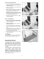
1
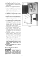
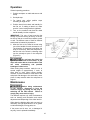
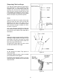
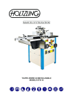
This Manual is Bookmarked
Operating Instructions and Parts Manual
Heavy-Duty Mortiser
Model 720HD
WMH TOOL GROUP
2420 Vantage Drive
Elgin, Illinois 60123
Ph.: 800-274-6848
www.wmhtoolgroup.com
Part No. M-1791309
Revision A 7/05
Copyright © WMH Tool Group
This manual has been prepared for the owner and operators of a Powermatic Model 720HD Mortiser. Its
purpose, aside from machine operation, is to promote safety using accepted operating and maintenance
procedures. To obtain maximum life and efficiency from your mortiser and to aid in using it safely, please
read this manual thoroughly and follow the instructions carefully.
Warranty and Service
WMH Tool Group warrants every product it sells. If one of our tools needs service or repair, one of our
Authorized Repair Stations located throughout the United States can provide quick service or information.
In most cases, a WMH Tool Group Repair Station can assist in authorizing repair work, obtaining parts, or
perform routine or major maintenance repair on your Powermatic product.
For the name of an Authorized Repair Station in your area, please call 1-800-274-6848, or visit our web
site at www.wmhtoolgroup.com
More Information
Remember, WMH Tool Group is consistently adding new products to the line. For complete, up-to-date
product information, check with your local WMH Tool Group distributor, or visit our web site at
www.wmhtoolgroup.com
WMH Tool Group Warranty
WMH Tool Group makes every effort to assure that its products meet high quality and durability standards
and warrants to the original retail consumer/purchaser of our products that each product be free from
defects in materials and workmanship as follows: 1 YEAR LIMITED WARRANTY ON ALL PRODUCTS
UNLESS SPECIFIED OTHERWISE. This Warranty does not apply to defects due directly or indirectly to
misuse, abuse, negligence or accidents, normal wear-and-tear, repair or alterations outside our facilities,
or to a lack of maintenance.
WMH TOOL GROUP LIMITS ALL IMPLIED WARRANTIES TO THE PERIOD SPECIFIED ABOVE,
BEGINNING FROM THE DATE THE PRODUCT WAS PURCHASED AT RETAIL. EXCEPT AS STATED
HEREIN, ANY IMPLIED WARRANTIES OR MERCHANTABILITY AND FITNESS ARE EXCLUDED.
SOME STATES DO NOT ALLOW LIMITATIONS ON HOW LONG THE IMPLIED WARRANTY LASTS,
SO THE ABOVE LIMITATION MAY NOT APPLY TO YOU. IN NO EVENT SHALL WMH TOOL GROUP
BE LIABLE FOR DEATH, INJURIES TO PERSONS OR PROPERTY, OR FOR INCIDENTAL,
CONTINGENT, SPECIAL, OR CONSEQUENTIAL DAMAGES ARISING FROM THE USE OF OUR
PRODUCTS. SOME STATES DO NOT ALLOW THE EXCLUSION OR LIMITATION OF INCIDENTAL
OR CONSEQUENTIAL DAMAGES, SO THE ABOVE LIMITATION OR EXCLUSION MAY NOT APPLY
TO YOU.
To take advantage of this warranty, the product or part must be returned for examination, postage
prepaid, to an Authorized Repair Station designated by our office. Proof of purchase date and an
explanation of the complaint must accompany the merchandise. If our inspection discloses a defect, we
will either repair or replace the product at our discretion, or refund the purchase price if we cannot readily
and quickly provide a repair or replacement. We will return the repaired product or replacement at WMH
Tool Group’s expense, but if it is determined there is no defect, or that the defect resulted from causes
not within the scope of WMH Tool Group’s warranty, then the user must bear the cost of storing and
returning the product. This warranty gives you specific legal rights; you may also have other rights, which
vary from state to state.
WMH Tool Group sells through distributors only. Members of the WMH Tool Group reserve the right to
effect at any time, without prior notice, alterations to parts, fittings and accessory equipment, which they
may deem necessary for any reason whatsoever.
2
Table of Contents
Warranty and Service ..............................................................................................................................2
Table of Contents ....................................................................................................................................3
Warning...................................................................................................................................................4
Introduction..............................................................................................................................................6
Specifications ..........................................................................................................................................6
Unpacking ...............................................................................................................................................7
Contents of the Shipping Container ......................................................................................................7
Assembly.................................................................................................................................................8
Installing Handle...................................................................................................................................8
Installing Wood Table...........................................................................................................................8
Installing Bushing, Chisel and Auger.....................................................................................................9
Grounding Instructions.............................................................................................................................9
Extension cords..................................................................................................................................10
Adjustments...........................................................................................................................................11
Squaring Table To Chisel ...................................................................................................................11
Setting Table to Vertical Position ........................................................................................................11
Table Removal and Storage ...............................................................................................................11
Chuck Extension Adaptor ...................................................................................................................12
Depth Setting Rod..............................................................................................................................12
Head Movement.................................................................................................................................12
Clamp ................................................................................................................................................13
Stock Stop..........................................................................................................................................13
Setting Lateral Stops ..........................................................................................................................13
Chisel Parallel to Workpiece...............................................................................................................14
Lower Work Support...........................................................................................................................14
Re-setting the Head ...........................................................................................................................14
Gib Adjustment...................................................................................................................................14
Tool Storage ......................................................................................................................................15
Operating Controls.................................................................................................................................15
Operation...............................................................................................................................................16
Sharpening Chisel and Auger.............................................................................................................17
Lubrication .........................................................................................................................................17
Replacement Parts ................................................................................................................................18
720HD Heavy Duty Mortiser ...............................................................................................................19
Parts List: 720HD Heavy Duty Mortiser...............................................................................................20
Electrical Connections ...........................................................................................................................23
3
Warning
1. Read and understand the entire owners manual before attempting assembly or operation.
2. Read and understand the warnings posted on the machine and in this manual. Failure to comply with
all of these warnings may cause serious injury.
3. Replace the warning labels if they become obscured or removed.
4. This mortiser is designed and intended for use by properly trained and experienced personnel only. If
you are not familiar with the proper and safe operation of a mortiser, do not use until proper training
and knowledge have been obtained.
5. Do not use this mortiser for other than its intended use. If used for other purposes, WMH Tool Group
disclaims any real or implied warranty and holds itself harmless from any injury that may result from
that use.
6. Always wear approved safety glasses/face shields while using this mortiser. Everyday eyeglasses
only have impact resistant lenses; they are not safety glasses.
7. Before operating this mortiser, remove tie, rings, watches and other jewelry, and roll sleeves up past
the elbows. Remove all loose clothing and confine long hair. Non-slip footwear or anti-skid floor strips
are recommended. Do not wear gloves.
8. Wear ear protectors (plugs or muffs) during extended periods of operation.
9. Some dust created by power sanding, sawing, grinding, drilling and other construction activities
contain chemicals known to cause cancer, birth defects or other reproductive harm. Some examples
of these chemicals are:
• Lead from lead based paint.
• Crystalline silica from bricks, cement and other masonry products.
• Arsenic and chromium from chemically treated lumber.
Your risk of exposure varies, depending on how often you do this type of work. To reduce your
exposure to these chemicals, work in a well-ventilated area and work with approved safety
equipment, such as face or dust masks that are specifically designed to filter out microscopic
particles.
10. Do not operate this machine while tired or under the influence of drugs, alcohol or any medication.
11. Make certain the machine is properly grounded.
12. Make all machine adjustments or maintenance with the machine unplugged from the power source.
13. Remove adjusting keys and wrenches. Form a habit of checking to see that keys and adjusting
wrenches are removed from the machine before turning it on.
14. Keep safety guards in place at all times when the machine is in use. If removed for maintenance
purposes, use extreme caution and replace the guards immediately.
15. Check damaged parts. Before further use of the machine, a guard or other part that is damaged
should be carefully checked to determine that it will operate properly and perform its intended
function. Check for alignment of moving parts, binding of moving parts, breakage of parts, mounting
and any other conditions that may affect its operation. A guard or other part that is damaged should
be properly repaired or replaced.
16. Provide for adequate space surrounding work area and non-glare, overhead lighting.
17. Keep the floor around the machine clean and free of scrap material, oil and grease.
18. Keep visitors a safe distance from the work area. Keep children away.
19. Make your workshop child proof with padlocks, master switches or by removing starter keys.
20. Give your work undivided attention. Looking around, carrying on a conversation and “horse-play” are
careless acts that can result in serious injury.
4
21. Maintain a balanced stance at all times so that you do not fall or lean against the auger and chisel or
other moving parts. Do not overreach or use excessive force to perform any machine operation.
22. Use the right tool at the correct speed and feed rate. Do not force a tool or attachment to do a job for
which it was not designed. The right tool will do the job better and safer.
23. Use recommended accessories; improper accessories may be hazardous.
24. Maintain tools with care. Keep augers and chisels sharp and clean for the best and safest
performance. Follow instructions for lubricating and changing accessories.
25. Make sure the work piece is securely clamped against table and/or fence. Never use your hand to
hold the work piece.
26. Do not turn on the power while the auger or chisel is contacting a workpiece.
27. Turn off the machine before cleaning. Use a brush or compressed air to remove chips or debris — do
not use your hands.
28. Do not stand on the machine. Serious injury could occur if the machine tips over.
29. Never leave the machine running unattended. Turn the power off and do not leave the mortiser until
the auger comes to a complete stop.
30. Remove loose items and unnecessary work pieces from the area before starting the machine.
Familiarize yourself with the following safety notices used in this manual:
This means that if precautions are not heeded, it may result in minor injury and/or
possible machine damage.
This means that if precautions are not heeded, it may result in serious injury or possibly
even death.
- - SAVE THESE INSTRUCTIONS - -
5
Introduction
This manual is provided by WMH Tool Group covering the safe operation and maintenance procedures
for a Model 720HD Heavy-Duty Mortiser. This manual contains instructions on installation, safety
precautions, general operating procedures, maintenance instructions and parts breakdown. This machine
has been designed and constructed to provide years of trouble free operation if used in accordance with
instructions set forth in this manual. If there are any questions or comments, please contact either your
local supplier or WMH Tool Group. WMH Tool Group can also be reached at our web site:
www.wmhtoolgroup.com.
Specifications
Model Number ................................................................................................................................ 720HD
Stock Number.............................................................................................................................. 1791309
Chuck Capacity (in.).............................................................................................................................. 1/2
Spindle Taper ................................................................................................................................... JT33
Bushing Inside Diameter (in.) ..........................................................................................3/4, 5/8 and 1-1/8
Chisel Stroke (in.) .............................................................................................................................. 6-1/8
Maximum Chisel Travel (in.):
Side to Side.................................................................................................................................... 9-1/8
Front to Back.................................................................................................................................. 3-3/8
Table Size (L x W)(in.) ......................................................................................................... 14-5/8 x 7-1/8
Maximum Workpiece Height – without Table (in.)................................................................................... 46
Maximum Workpiece Height – with Table (in.).................................................................................. 11-1/2
Clamp Surface (L x W)(in.)........................................................................................................... 8 x 2-3/4
Table Tilt (deg.) ..................................................................................................................90 left, 45 right
Fence Size (L x W)(in.) ...................................................................................................... 20-1/2 x 11-3/4
Base Size (L x W)(in.) ........................................................................................................ 25-1/2 x 21-1/2
Overall Height (in.)................................................................................................................................. 80
Motor...........................................................................................................TEFC, 1.5HP, 1Ph, 230V only
Motor Speed (RPM).......................................................................................................................... 1,720
Approximate Shipping Weight (lbs.) ..................................................................................................... 575
Approximate Net Weight (lbs.) ............................................................................................................. 490
The above specifications were current at the time this manual was published, but because of our policy of
continuous improvement, WMH Tool Group reserves the right to change specifications at any time and
without prior notice, without incurring obligations.
6
Contents of the Shipping Container
Unpacking
1
1
1
1
3
Remove all crating and plastic from around the
Mortiser. Check for shipping damage; report any
damage immediately to your distributor and
shipping agent. Do not discard any shipping
material until the Mortiser is assembled and
running properly.
Open the cabinet rear door and remove any
boxes and accessory items. Compare these with
the following parts list to make sure all parts are
intact. Missing parts, if any, should be reported
to your distributor. Read the instruction manual
thoroughly for assembly, maintenance and
safety instructions.
3
4
1
1
1
2
1
1
1
Mortiser
Handle
Chisel and Auger set – 3/4”
Chisel and Auger set - 1”
Bushings - 5/8”, 3/4” and 1-1/8” I.D.
(NOTE: The 5/8” bushing is already installed
on the mortiser)
Combination Wrenches: 12-14, 17-19, 22-24
Hex (Allen) Wrenches: 3, 4, 5 and 6mm
Chuck Key
Chuck Extension Adaptor
Wood Table
Phillips Flat Head Screws, M6 x 20L
Reversible (Cross Point/Flat Head)
Screwdriver
Owner's Manual
Warranty Card
Read and understand the entire contents of this manual before attempting set-up
or operation! Failure to comply may cause serious injury.
7
Assembly
Tools required for assembly
forklift or hoist with straps/slings
14mm wrench (provided)
4 and 6mm hex wrenches (provided)
1. Remove the four screws that secure the
Mortiser to the wood pallet, using a 14mm
wrench.
2. With a forklift or hoist, lift the machine off the
pallet and into its desired location.
3. The Mortiser should be located in a dry
area, on a sturdy, level floor, and with
sufficient lighting. Leave plenty of space
around the machine for operations and
routine maintenance work.
4. If desired, the Mortiser can be further
stabilized by securing it to the floor, using
lag screws through the four holes in the
base.
The mortiser should be
disconnected from the power source during
assembly procedures.
5. Unpainted areas of the machine have been
treated with a rust preventative. This should
be removed with a soft cloth and a mild
solvent. Do not use paint thinner, lacquer
thinner, gasoline or mineral spirits; these will
damage painted surfaces and plastic parts.
Do not use an abrasive pad.
Installing Handle
1. Use a 4mm hex wrench to remove the
screw, washer and spring from the shaft
(Figure 1).
2. Mount the hub of the handle onto the shaft
as shown. Make sure the hub slides all the
way onto the shaft.
Figure 1
3. Re-install spring, washer and screw. Tighten
screw.
Installing Wood Table
1. To install the wood table, first remove the
right hand screw at the right of the clamp
(Figure 2), with a 6mm hex wrench, and
loosen the left hand screw from beneath.
Pivot the clamp out of the way.
2. Mount the wood table with two flat head
screws as shown.
Figure 2
3. Re-position the clamp and install the screw.
8
Installing Bushing, Chisel and Auger
1. The mortiser should be disconnected from
power source.
2. Open the chuck access cover (A, Figure 3).
3. Insert a bushing (B, Figure 3) into the hole
with the bushing’s hole facing the front
toward the set screw (C, Figure 3).
NOTE: The Mortiser is shipped with the 5/8”
bushing pre-installed.)
4. Tighten the set screw (C, Figure 3) with a
4mm hex wrench just enough to hold
bushing in place.
5. Place the chisel (D, Figure 3) and auger (E,
Figure 3) beneath the bushing and allow the
auger to rest upon the table while pushing
the chisel up through the bushing.
6. The cutting portion of the auger must clear
the chisel by about 1/16” to 3/16”,
depending upon the type of wood to be
worked. Place a “spacer” of 1/8” to 3/16”
diameter (a hex wrench works well)
between bushing and chisel, and push
chisel up until it contacts the spacer.
Figure 3
7. Tighten the set screw (C, Figure 3) to hold
the chisel in place, and remove spacer.
8. Push the auger up through the chisel
opening and into the chuck as far as it will
go. Tighten the auger in the chuck using the
chuck key.
9. Loosen the set screw (C, Figure
push the chisel all the way up
contacts the bushing. This should
the proper distance so that the
portion of the auger clears the
Tighten the set screw (C, Figure 3).
3) and
until it
provide
cutting
chisel.
NOTE: Set the slot in the side of the chisel
to the left or right, if the cut is to be done
laterally; and front or back if the cut is to be
done front to back. The chisel slot should
always be positioned so chips are being
released into the already-cut part of the
workpiece.
10. Close the chuck access cover (A, Figure 3)
before operating.
Grounding Instructions
Electrical connections must
be made by a qualified electrician in
compliance with all relevant codes. This
machine must be properly grounded to help
prevent electrical shock and possible fatal
injury.
9
This machine must be grounded. In the event of
a malfunction or breakdown, grounding provides
a path of least resistance for electric current to
reduce the risk of electric shock.
Improper connection of the equipmentgrounding conductor can result in a risk of
electric shock. The conductor, with insulation
having an outer surface that is green with or
without yellow stripes, is the equipmentgrounding conductor. If repair or replacement of
the electric cord or plug is necessary, do not
connect the equipment-grounding conductor to a
live terminal.
Check with a qualified electrician or service
personnel if the grounding instructions are not
completely understood, or if in doubt as to
whether the tool is properly grounded. Use only
three wire extension cords that have three-prong
grounding plugs and three-pole receptacles that
accept the tool’s plug.
The Mortiser is factory wired for 230 volt. You
may either install a plug or “hard-wire” the
machine directly to a control panel.
If you are connecting a plug, use a proper
UL/CSA listed grounding plug suitable for 230
volt operation, similar to that shown in Figure 4.
The Mortiser with a 230 volt plug should only be
connected to an outlet having the same
configuration. No adapter is available or should
be used with the 230 volt plug.
If the Mortiser is to be hard-wired to a panel,
make sure a disconnect is available for the
operator. During hard-wiring of the Mortiser,
make sure the fuses have been removed or the
breakers have been tripped in the circuit to
which the Mortiser will be connected. Place a
warning placard on the fuse holder or circuit
breaker to prevent it being turned on while the
machine is being wired.
Figure 4
Recommended Gauges (AWG) of Extension Cords
Extension Cord Length *
Make sure the voltage of your power supply
matches the specifications on the motor plate of
the Mortiser.
Extension cords
If an extension cord is necessary, make sure the
cord rating is suitable for the amperage listed on
the machine’s motor plate. An undersized cord
will cause a drop in line voltage resulting in loss
of power and overheating.
Use the chart in Figure 5 as a general guide in
choosing the correct size cord. If in doubt, use
the next heavier gauge. The smaller the gauge
number, the heavier the cord.
Amps
25
feet
50
feet
75
feet
100
feet
150
feet
200
feet
<5
16
16
16
14
12
12
5 to 8
16
16
14
12
10
NR
8 to 12
14
14
12
10
NR
NR
12 to 15
12
12
10
10
NR
NR
15 to 20
10
10
10
NR
NR
NR
21 to 30
10
NR
NR
NR
NR
NR
*based on limiting the line voltage drop to 5V at 150% of the
rated amperes.
NR: Not Recommended.
Figure 5
10
Adjustments
Squaring Table To Chisel
1. Place a square upon the table and against
the chisel, as shown in Figure 6.
2. If the table and chisel are not perpendicular
to each other, loosen the table’s stud with
the attached hex wrench (A, Figure 6).
3. Loosen the locking handle (B, Figure 6) and
adjust the table until the table and chisel are
square.
4. Re-tighten the stud (A, Figure 6) and locking
handle (B, Figure 6).
Figure 6
5. Make sure the pointer aligns with zero on
the scale. Loosening the screw on the
pointer will allow slight adjustment of the
pointer if necessary.
NOTE: The locking handle (B, Figure 6) can be
rotated out of the way. Simply lift up on the
handle, rotate it on the pin, then release the
handle, making sure it seats itself properly on
the pin.
Setting Table to Vertical Position
For table angles from 45° to 90°:
1. Loosen the stud (A, Figure 7).
2. Unscrew and remove the locking handle (B,
Figure 7).
3. Rotate the table to vertical position and
install the locking handle (B, Figure 7) into
the other hole as shown.
4. Adjust the table to the desired angle and
tighten both stud and locking handle.
Figure 7
Table Removal and Storage
The table can be removed for mortising large
workpieces using the lower work support.
First remove the locking handle (B, Figure 7),
then unscrew and remove the stud (A, Figure 7).
The table can be stored in the rack at the side of
the cabinet. See Figure 8.
Figure 8
11
Chuck Extension Adaptor
The provided Chuck Extension Adaptor is used
to lower the chuck for use with after-market
chisels (chisels other than those supplied with
your machine) that may require a spacer due to
varying lengths in shanks.
1. To install the adaptor, first remove the chisel
and auger.
2. It may be necessary to remove the bushing
to provide enough clearance when installing
the chuck and adaptor. If so, loosen the set
screw and remove the bushing.
3. Hold the spindle stationary by placing a
wrench on the flats of the spindle (see
Figure 9). With your other hand, insert the
chuck key into the chuck and use it to twist
the entire chuck, until the chuck releases
from the tapered spindle. Do not allow the
chuck to drop, as it can be damaged.
Figure 9
4. Push the adaptor into the chuck (Figure 9).
Then push this assembly onto the spindle.
5. Re-install the bushing and secure it loosely
with the set screw.
6. Re-install the chisel and auger. See
“Installing Bushing, Chisel and Auger”.
Depth Setting Rod
The depth setting rod (Figure 10) limits the
depth of the stroke.
1. Lower the mortising head until the chisel is
at the desired depth.
2. Loosen the locking handle and slide the
depth rod down until the collar contacts the
block.
3. Tighten the locking handle.
Figure 10
Head Movement
The three handles for head movement
(explained below) are spring loaded, and can be
adjusted to different positions for the
convenience of the operator. Pull up on the
handle close to its hub and rotate it, allowing it
to drop back down onto the pin. See Figure 11.
Make sure the handle re-seats itself properly on
the pin.
Figure 11
12
Lateral (X Axis)
Use the handle (A, Figure 12) to move the head
right or left. The lateral stops should be set in
accordance with the length of the mortise cut
(see “Setting Lateral Stops”).
Up/Down (Z Axis)
Handle B, Figure 12.
Forward/Backward (Y Axis)
Loosen the Y-Axis locking handle (shown in
Figure 18) and move the handle (C, Figure 12).
NOTE: When making lateral cuts the Y-Axis
locking handle (Figure 18) should be tightened.
Figure 12
Clamp
The clamp (Figure 13) has a quick release
feature; push the handle forward to move the
jaw against the workpiece, then further tighten
the clamp by rotating the handle. The clamp jaw
can also be retracted by loosening the handle
about a half turn, and then pulling it outward.
The clamp can be swiveled for tapered
workpieces. Loosen both screws (one is shown
in Figure 13) and swivel the clamp as needed.
Re-tighten both screws.
If you do not wish to mar a soft workpiece, you
can mount a board to the face of the clamp jaw,
using screws (not provided) through the two
holes in the jaw.
Figure 13
Stock Stop
The stock stop, shown in Figure 13, is useful for
repetitive cuts of the same length, and can be
mounted to either end of the fence. Loosen the
wing screws to adjust.
Setting Lateral Stops
Loosen the locking handles and slide the lateral
stops (Figure 14) to the desired position. Retighten the locking handles.
Figure 14
13
Chisel Parallel to Workpiece
For accurate mortise cuts, the chisel must be
parallel to the workpiece. The workpiece should
be cut square for this adjustment to be accurate.
Check and adjust this parallelism as follows:
1. Move the head forward far enough that the
workpiece can be inserted between fence
and chisel.
2. Slightly loosen the set screw to allow the
chisel to be rotated.
3. Move the head back carefully until the face
of the chisel rests against the workpiece, but
do not force. See Figure 15.
Figure 15
4. If needed, further adjust the chisel by hand.
5. Tighten set screw, making sure the chisel
maintains contact with the bushing.
Lower Work Support
To use the lower work support, remove the table
(see “Table Removal and Storage”). Loosen the
locking handle (Figure 16) and slide the lower
work support into position. Re-tighten the handle
securely.
Re-setting the Head
The head can be adjusted in order to achieve
the maximum workpiece height.
Figure 16
1. Place a block of wood for support between
the head and fence (Figure 17). Lower the
head until it rests upon the block.
2. Loosen only slightly the hex nut (A, Figure
17).
3. Pull down the handle (B, Figure 17) until the
cylinder (C, Figure 17) bottoms out.
4. Tighten the hex nut (A, Figure 17).
Gib Adjustment
The tightness of the gibs has been set at the
factory and should not require adjustment. As
parts wear through long-term use, or “play”
develops in the gib, adjustments can be made
as follows. NOTE: Gib tightness should be just
enough to allow smooth movement without
binding.
Figure 17
Gib for Vertical Movement
1. Slightly loosen the three hex cap screws (D,
Figure 17) which hold the gib.
2. Turn the gib screws (E, Figure 17) until any
play is removed.
3. Re-tighten the hex cap screws (D, Figure
17) securely.
14
Gib for Front-to-Back Movement
1. Remove the two screws on the pleated dust
cover (F, Figure 18) and move the dust
cover out of the way.
2. Loosen the three hex nuts (G, Figure 18)
with a 10mm wrench.
3. Turn the three set screws (H, Figure 18)
with a 3mm hex wrench, until play is
eliminated on the gib (J, Figure 18).
4. Re-tighten the three hex nuts (G, Figure 18)
NOTE: Hold the set screws so they do not
turn during the tightening process.
Figure 18
5. Re-install the pleated dust cover (F, Figure
18) before operating.
Gib for Lateral Movement
1. Remove the two screws on the pleated dust
cover (F, Figure 19) and move the dust
cover out of the away.
2. Loosen the three hex nuts (K, Figure 19)
with a 10mm wrench.
3. Turn the three set screws (L, Figure 19) until
all play is eliminated on the gib (M, Figure
19).
4. Re-tighten the three hex nuts (K, Figure 19).
NOTE: Hold the set screws so they do not
turn during the tightening process.
Figure 19
5. Re-install the pleated dust cover (F, Figure
19) before operating.
Tool Storage
The cabinet shelf contains a perforated cushion
for the accessories, as shown in Figure 20.
Operating Controls
The magnetic starter with control buttons is
mounted to the motor. Press the “start” button to
begin rotation of the auger. Press the “stop”
button to stop rotation of the auger. The auger
will quickly coast to a stop after the “stop” button
is pressed.
Figure 20
The magnetic starter is a valuable safety feature
of the Mortiser. Should electrical power
suddenly be cut off while the mortiser is being
operated, the magnetic starter will prevent the
machine from immediately re-starting when
power is restored. To re-start the Mortiser you
must press the “on” button.
15
Operation
General operating procedure:
1. Position workpiece on table and secure with
clamp.
2. Set depth stop.
3. For lateral cuts, adjust positive stops
according to length of cut.
4. Position head front-to-back and laterally for
the first cut. If making a lateral cut, make
sure the Y-axis locking handle is tightened.
5. Turn on the machine and feed the chisel
and bit steadily into the workpiece.
IMPORTANT: The rate of feed must be fast
enough to prevent burning at the tip of the bit,
but not so fast as to cause the machine to slow
or stall. The different rates of feed for different
woods must be learned by experience.
6. After the first cut, the head is moved using
one of the handles for each successive cut.
The direction of movement must allow the
chips to clear freely. Move the workpiece so
that the slot in the chisel is releasing chips
into the already-cut part of the workpiece
(Figure 21).
Figure 21
Do not have the chisel slot
against the blind end of the mortise, as the
chips will not be able to clear the chisel. This
can cause overheating and possible
breakage of chisel or bit.
When cutting deep mortises, make the cut in
several stages of approximately 1” each, to
allow chips to clear. When cutting throughmortises, to prevent breakout at the back of the
workpiece and damage to the work table, use a
piece of scrap material under the workpiece as
support.
Maintenance
Before doing maintenance
on the mortiser, disconnect it from the
electrical supply by pulling out the plug or
switching off the main switch. Failure to
comply may cause serious injury.
The Mortiser requires only minor maintenance,
such as cleaning and lubrication and routine
adjustment and sharpening of the chisel and bit.
Wipe down the Mortiser after each use and, as
necessary, use light applications of oil or grease
to lubricate linkages, moving parts, etc.
If the power cord is worn, cut, or damaged in
any way, have it replaced immediately.
16
Sharpening Chisel and Auger
The chisel and auger should be kept sharp for
best performance. If cutting operations require
excessive force, the chisel and/or auger are
probably dull and should be sharpened. Blunt
edges will give inaccurate mortises and can lead
to overheating and breakage of chisel or auger.
If chisel and auger are badly worn and become
difficult to sharpen, they should be replaced.
Chisel
Sharpen the chisel with a mortise chisel cutter
with the correct size pilot. (Pilot size will differ
depending on the size of your chisel.) Two or
three turns of the cutter in a carpenter’s brace
chuck should be enough to sharpen the chisel,
as shown in Figure 22.
Use a small, triangular, smooth file to relieve the
inner corners of the chisel (Figure 23). Remove
any burrs from the outside of the chisel with a
fine oilstone.
Figure 22
Auger
Sharpen the auger by using a small, smooth file,
following the original shape of the auger. File the
inside edge of the spur, the sides of the brad
point, and the cutting edge inwards toward the
flute of the auger. See Figure 24.
Do not file the outside edge of the spur, as this
will affect the diameter of the auger.
Lubrication
All ball bearings are sealed. They require no
further lubrication.
Figure 23
Periodically grease the gears, racks, and table
pivot points with a #2 tube grease.
Periodically clean and apply grease or oil to any
exposed machine surfaces, such as dove-tailed
ways and slides.
Figure 24
17
Troubleshooting
Trouble
Probable Cause
Remedy
No incoming power.
Check all plug connections.
Fuse blown, or circuit breaker tripped.
Replace fuse, or reset circuit breaker.
Cord damaged.
Replace cord.
Motor bad.
Contact WMH technical service.
Extension cord too light or too long.
Replace with adequate size and
length cord.
Low current.
Contact a qualified electrician.
Mortiser vibrates
excessively.
Stand on uneven surface.
Machine should be placed on level
floor; use shims if necessary.
Noisy Operation.
Auger contacting chisel.
Increase offset of auger in relation to
chisel. See page 9.
Chips not clearing from hole or auger.
Retract auger frequently to remove
chips. Make sure chisel slot opens
toward area already cut.
Dull auger.
Resharpen, or replace auger.
Feeding auger into workpiece too
slowly.
Increase feed rate.
Auger sharpened incorrectly.
Resharpen auger correctly (page 17).
Chuck jaws not tight.
Tighten chuck jaws.
Bent auger.
Replace auger.
Auger or chuck not installed properly.
Reinstall the chuck, or auger properly.
No backing board used.
Place a scrap board underneath the
workpiece to prevent splintering.
Workpiece not clamped properly,
pinching the auger.
Support or clamp workpiece firmly.
Excessive feed rate.
Decrease feed rate.
Chuck jaws not tight.
Tighten chuck jaws.
Mortiser will not start.
Drill bit does not
come up to speed.
Workpiece Burns.
Drill bit wanders.
Wood splinters on the
underside.
Drill bit binds in
workpiece.
Replacement Parts
Replacement parts are listed on the following pages. To order parts or reach our service department, call
1-800-274-6848 between 7:30 a.m. and 6:00 p.m. (CST), Monday through Friday. Having the Model
Number and Serial Number of your machine available when you call will allow us to serve you quickly and
accurately.
18
720HD Heavy Duty Mortiser
19
Parts List: 720HD Heavy Duty Mortiser
Index No. Part No.
Description
Size
Qty
1...............720HD-101.............. Stand................................................................. ................................... 1
1...............720HD-101.............. Stand................................................................. ................................... 1
2...............720HD-102.............. X Axis Slide Base .............................................. ................................... 1
3...............720HD-103.............. Socket Head Cap Screw.................................... M10x65 ...................... 4
4...............720HD-104.............. Set Screw.......................................................... M10x55 ...................... 6
5...............720HD-105.............. X Axis Gear Rack .............................................. ................................... 1
6...............TS-1503041 ............ Socket Head Cap Screw.................................... M6x16 ........................ 7
7...............720HD-107.............. Rod Support ...................................................... ................................... 2
8...............TS-1503071 ............ Socket Head Cap Screw.................................... M6x30 ........................ 4
9...............TS-1523011 ............ Set Screw.......................................................... M6x6 .......................... 4
10 .............6294144.................. Setting Rod........................................................ ................................... 1
11 .............6294143.................. Setting Collar..................................................... ................................... 3
12 .............720HD-112.............. Locking Handle.................................................. M6x10 ........................ 2
13 .............720HD-113.............. X Axis Slide ...................................................... ................................... 1
14 .............720HD-114.............. Dovetail Gib....................................................... ................................... 1
15 .............720HD-115.............. Wooden Table Top ............................................ ................................... 1
16 .............720HD-116.............. Gear Housing .................................................... ................................... 1
17 .............TS-1506031 ............ Socket Head Cap Screw.................................... M12x30 ...................... 2
18 .............TS-1540081 ............ Hex Nut ............................................................. M12 ............................ 1
19 .............TS-1492041 ............ Hex Cap Screw.................................................. M12x40 ...................... 1
20 .............BB-6004ZZ.............. Bearing.............................................................. #6004ZZ ..................... 2
21 .............720HD-121.............. X Axis Shaft....................................................... ................................... 1
22 .............720HD-122.............. Key.................................................................... 5x5x30........................ 3
23 .............720HD-123.............. Feed Gear ......................................................... ................................... 1
24 .............TS-1523041 ............ Set Screw.......................................................... M6x12 ........................ 4
25 .............720HD-125.............. Spacer............................................................... ................................... 1
26 .............TS-1514021 ............ Flat Head Socket Screw..................................... M6x16 ........................ 5
27 .............720HD-127.............. X Axis Handle .................................................... ................................... 1
28 .............720HD-128.............. Plastic Handle Grip ............................................ ................................... 3
29 .............6294166.................. Spring................................................................ ................................... 3
30 .............6294167.................. Washer.............................................................. ................................... 3
31 .............720HD-131.............. Y Axis Shaft....................................................... ................................... 1
32 .............TS-1525011 ............ Set Screw.......................................................... M10x10 ...................... 1
33 .............720HD-133.............. Y Axis Feed Gear .............................................. ................................... 1
34 .............720HD-134.............. Retaining Ring ................................................... STW-20 ...................... 2
35 .............720HD-135.............. Y Axis Handle .................................................... ................................... 1
36 .............720HD-136.............. Y Axis Slide ....................................................... ................................... 1
37 .............720HD-137.............. Y Axis Gear Rack .............................................. ................................... 1
38 .............720HD-138.............. Dovetail Gib....................................................... ................................... 1
39 .............720HD-139.............. Set Screw.......................................................... M6x40 ........................ 6
40 .............TS-1540041 ............ Hex Nut ............................................................. M6 .............................. 6
41 .............720HD-141.............. Locking Handle.................................................. M6x38 ........................ 1
42 .............720HD-142.............. Column.............................................................. ................................... 1
43 .............TS-2360121 ............ Flat Washer ....................................................... M12 ............................ 3
44 .............TS-1506051 ............ Socket Head Cap Screw.................................... M12x40 ...................... 3
45 .............720HD-145.............. Z Axis Shaft ....................................................... ................................... 1
46 .............720HD-146.............. Washer.............................................................. D34.5xd20x0.4t .......... 1
47 .............720HD-147.............. Pleated Dust Cover............................................ ................................... 1
48 .............720HD-148.............. Z Axis Handle .................................................... ................................... 1
49 .............720HD-149.............. Spring................................................................ ................................... 1
50 .............720HD-150.............. Steel Ball ........................................................... D8 .............................. 1
51 .............720HD-151.............. Gib .................................................................... ................................... 1
52 .............TS-1504031 ............ Socket Head Cap Screw.................................... M8x16 ........................ 3
53 .............720HD-153.............. Screw ................................................................ ................................... 3
54 .............720HD-154.............. Z Axis Slide Base............................................... ................................... 1
55 .............720HD-155.............. Z Axis Gear Rack............................................... ................................... 1
56 .............720HD-156.............. Cylinder Fitting Shaft (Short).............................. ................................... 1
20
57 .............720HD-157.............. Cylinder Head.................................................... ................................... 2
58 .............720HD-158.............. Cylinder ............................................................. ................................... 1
59 .............720HD-159.............. Cylinder Fitting Shaft (Long)............................... ................................... 1
60 .............720HD-160.............. E-Ring ............................................................... ETW-7........................ 2
61 .............720HD-161.............. Stopper Block .................................................... ................................... 1
62 .............TS-1504061 ............ Socket Head Cap Screw.................................... M8x30 ........................ 2
63 .............720HD-163.............. Shelf Cushion .................................................... ................................... 1
64 .............720HD-164.............. Rubber Collar .................................................... 5x50 ........................... 1
65 .............TS-1550031 ............ Flat Washer ....................................................... M5 .............................. 3
66 .............TS-1481021 ............ Hex Cap Screw.................................................. M5x10 ........................ 3
67 .............720HD-167.............. Handle Bracket .................................................. ................................... 1
68 .............720HD-168.............. Headstock ......................................................... ................................... 1
69 .............720HD-169.............. Square Head Screw........................................... ................................... 1
70 .............TS-155010 .............. Flat Washer ....................................................... M16 ............................ 1
71 .............TS-2310162 ............ Hex Nut ............................................................. M16x1.5P ................... 1
72 .............720HD-172.............. Motor................................................................. 1-1/2HP, 230V, 1Ph.... 1
73 .............TS-1551041 ............ Lock Washer...................................................... M6 .............................. 4
74 .............TS-1482061 ............ Hex Cap Screw.................................................. M6x30 ........................ 4
75 .............6294171.................. Chuck ................................................................ JT33-13mm ................ 1
76 .............6294198.................. Bushing ............................................................. 1-1/8”.......................... 1
.................6294221.................. Bushing (not shown) .......................................... 3/4”............................. 1
.................6294222.................. Bushing (not shown) .......................................... 5/8”............................. 1
77 .............TS-1524041 ............ Set Screw.......................................................... M8x16 ........................ 2
78 .............720HD-178.............. Chuck Access Cover.......................................... ................................... 1
79 .............720HD-179.............. Retaining Ring ................................................... ISTW-10 ..................... 1
80 .............720HD-180.............. Depth Setting Rod ............................................. ................................... 1
81 .............720HD-181.............. Locking Handle.................................................. M8x15 ........................ 1
82 .............TS-1533032 ............ Pan Head Screw................................................ M5x10 ........................ 2
83 .............720HD-183.............. Fence ................................................................ ................................... 1
84 .............TS-1505031 ............ Socket Head Cap Screw.................................... M10x25 ...................... 7
85 .............720HD-185.............. Guide Bracket (Upper) ....................................... ................................... 1
86 .............TS-1505061 ............ Socket Head Cap Screw.................................... M10x40 ...................... 2
87 .............TS-1525021 ............ Set Screw.......................................................... M10x12 ...................... 2
88 .............720HD-188.............. Guide Rod ......................................................... ................................... 1
89 .............720HD-189.............. Guide Bracket.................................................... ................................... 1
90 .............720HD-190.............. Support Bracket................................................. ................................... 1
91 .............720HD-191.............. Locking Handle.................................................. M12x60 ...................... 2
92 .............720HD-192.............. Guide Bracket (Lower) ....................................... ................................... 1
93 .............TS-1505131 ............ Socket Head Cap Screw.................................... M10x80 ...................... 2
94 .............720HD-194.............. Bracket .............................................................. ................................... 2
95 .............720HD-195.............. Table ................................................................. ................................... 1
96 .............TS-1504061 ............ Socket Head Cap Screw.................................... M8x30 ........................ 1
97 .............720HD-197.............. Pointer............................................................... ................................... 1
98 .............TS-2171012 ............ Pan Head Screw................................................ M4x6 .......................... 1
99 .............720HD-199.............. Scale ................................................................. ................................... 1
100 ...........6294187.................. Clamping Block.................................................. ................................... 1
101 ...........6294192.................. Locking Screw ................................................... ................................... 1
102 ...........6294223.................. Plastic Handle Sleeve ........................................ ................................... 1
103 ...........6294188.................. Rapid Nut .......................................................... ................................... 1
104 ...........6294186.................. Clamping Jaw .................................................... ................................... 1
105 ...........6294189.................. Friction Toe ....................................................... ................................... 1
106 ...........6294190.................. Spring................................................................ ................................... 1
107 ...........6294191.................. Rivet.................................................................. ................................... 5
108 ...........TS-1502051 ............ Socket Head Cap Screw.................................... M5x20 ........................ 4
109 ...........6294193.................. Stop Disc........................................................... ................................... 1
110 ...........6294148.................. Length Setting Rod (Rear) ................................. ................................... 1
111 ...........6294150.................. Length Setting Rod (Front)................................. ................................... 1
112 ...........TS-1550061 ............ Flat Washer ....................................................... M8 .............................. 2
113 ...........TS-1540021 ............ Hex Nut ............................................................. M4 ............................. 2
114 ...........TS-1550041 ............ Flat Washer ....................................................... M6 .............................. 5
115 ...........720HD-1115............ Special Washer ................................................. ................................... 1
21
116 ...........720HD-1116............ Allen Wrench ..................................................... ................................... 1
117 ...........TS-1514031 ............ Flat Head Socket Screw..................................... M6x20 ........................ 2
118 ...........720HD-1118............ Cover................................................................. ................................... 1
119 ...........TS-1534032 ............ Pan Head Screw................................................ M6x10 ........................ 5
120 ...........720HD-1120............ Switch Board ..................................................... ................................... 1
121 ...........TS-2245081 ............ Flat Head Socket Screw..................................... M5x8 .......................... 8
122 ...........720HD-1122............ Stud................................................................... ................................... 1
123 ...........720HD-1123............ Pleated Dust Cover............................................ ................................... 1
124 ...........720HD-1124............ Magnetic Switch................................................. ................................... 1
125 ...........TS-1532042 ............ Pan Head Screw................................................ M4x12 ........................ 2
126 ...........720HD-1126............ Sleeve ............................................................... ................................... 1
127 ...........720HD-1127............ Power Cord ....................................................... 1.25/3Cx3M ................ 1
128 ...........720HD-1128............ Motor Cord ........................................................ 1.25/3Cx0.8M ............. 1
129 ...........720HD-1129............ 90º Scale ........................................................... ................................... 1
130 ...........6294149.................. Length Setting Block.......................................... ................................... 1
131 ...........720HD-1131............ Hook.................................................................. ................................... 2
132 ...........TS-0152011 ............ Carriage Bolt...................................................... 5/16”-18x1” ................. 2
133 ...........TS-0680031 ............ Flat Washer ....................................................... 5/16”........................... 2
134 ...........TS-0561021 ............ Hex Nut ............................................................. 5/16”-18...................... 2
135 ...........6294145.................. Wing Screw ....................................................... M6x16 ........................ 4
136 ...........720HD-1136............ Table Holder...................................................... ................................... 1
137 ...........TS-1550061 ............ Flat Washer ....................................................... M8 .............................. 2
138 ...........720HD-1138............ Gear .................................................................. ................................... 1
139 ...........720HD-1139............ Washer.............................................................. ................................... 1
140 ...........720HD-1140............ Pad.................................................................... 26L ............................. 2
141 ...........TS-1504031 ............ Socket Head Cap Screw.................................... M8x16 ........................ 2
142 ...........TS-0267051 ............ Set Screw.......................................................... 1/4”-20x1/2” ................ 2
143 ...........TS-1504061 ............ Socket Head Cap Screw.................................... M8x30 ........................ 1
144 ...........720HD-1144............ Roll Pin.............................................................. M6x36 ........................ 1
145 ...........6294204.................. Chuck Key ......................................................... ................................... 1
146 ...........720HD-1146............ Door .................................................................. ................................... 1
147 ...........6294227.................. Pin..................................................................... ................................... 2
148 ...........6294228.................. Door Latch......................................................... ................................... 1
149 ...........TS-2171012 ............ Pan Head Screw................................................ M4x6 .......................... 2
150 ...........TS-1503051 ............ Socket Head Cap Screw.................................... M6x20 ........................ 3
151 ...........TS-0680011 ............ Flat Washer ....................................................... 3/16”........................... 2
152 ...........TS-0680021 ............ Flat Washer ....................................................... 1/4”............................. 4
153 ...........720HD-1153............ Cord Strain Relief .............................................. ................................... 2
154 ...........720HD-1154............ Cord Strain Relief .............................................. ................................... 1
155 ...........720HD-1155............ Cord Strain Relief .............................................. ................................... 1
156 ...........3005069.................. Chuck Extension Adaptor............................. ......................................... 1
22
Electrical Connections
23
WMH Tool Group
2420 Vantage Drive
Elgin, Illinois 60123
Phone: 800-274-6848
www.wmhtoolgroup.com
24