1
Installation and service
instructions
VIESMANN
for contractors
Electronic temperature differential control unit
Vitosolic 100
Type SD1
For applicability, see the last page
VITOSOLIC 100
5369 987 GB
4/2009
Please keep safe.
Safety instructions
Safety instructions
Please follow these safety instructions closely to prevent accidents and material losses.
Danger
This symbol warns against the
risk of injury.
!
Please note
This symbol warns against the
risk of material losses and environmental pollution.
Note
Details identified by the word "Note" contain additional information.
Working on the system
■ Isolate the system from the power supply and check that it is no longer 'live',
e.g. by removing a separate fuse or by
means of a main isolator.
■ Safeguard the system against unauthorised reconnection.
!
Target group
These instructions are exclusively
designed for qualified personnel.
■ Work on electrical equipment must
only be carried out by a qualified electrician.
■ The system must be commissioned by
the system installer or a qualified person authorised by the installer.
Regulations
Observe the following when working on
this system
■ all legal instructions regarding the prevention of accidents,
■ all legal instructions regarding environmental protection,
■ the Code of Practice of relevant trade
associations.
■ all current safety regulations as
defined by DIN, EN, DVGW, VDE and
all locally applicable standards
2
Please note
Electronic modules can be damaged by electrostatic discharges.
Touch earthed objects, such as
heating or water pipes, to discharge static loads.
Repair work
!
Please note
Repairing components that fulfil a
safety function can compromise
the safe operation of your heating
system.
Replace faulty components only
with original Viessmann spare
parts.
5369 987 GB
Safety instructions explained
Safety instructions
Safety instructions (cont.)
Ancillary components, spare and
wearing parts
Please note
Spare and wearing parts that
have not been tested together
with the heating system can compromise its function. Installing
non-authorised components and
non-approved modifications or
conversions can compromise
safety and may invalidate our
warranty.
For replacements, use only original spare parts supplied or
approved by Viessmann.
5369 987 GB
!
3
Index
Index
Installation instructions
Preparing for installation
Installation information......................................................................................... 6
System example 1................................................................................................ 6
System example 2................................................................................................ 11
System example 3................................................................................................ 18
System example 4................................................................................................ 24
Installation sequence
Fitting the solar control unit..................................................................................
Overview of electrical connections.......................................................................
Solar circuit pump.................................................................................................
Pump/valve at output R2......................................................................................
High limit safety cut-out........................................................................................
Collector temperature sensor...............................................................................
Cylinder temperature sensor................................................................................
Temperature sensor.............................................................................................
Power supply........................................................................................................
35
36
36
38
39
40
41
41
42
Service instructions
Commissioning
Switching the power ON.......................................................................................
Navigation through the menu...............................................................................
Selecting the system scheme...............................................................................
Setting system parameters...................................................................................
Resetting system parameters...............................................................................
Carrying out a relay test.......................................................................................
44
44
44
45
45
45
Service scans
Scanning temperatures and operating conditions................................................ 46
Function description
Parameter overview.............................................................................................
System scheme....................................................................................................
Collector limit temperature...................................................................................
Collector cooling function.....................................................................................
Minimum collector temperature limit.....................................................................
4
49
51
62
62
62
5369 987 GB
Troubleshooting
Fault messages.................................................................................................... 47
Checking sensors................................................................................................. 47
Changing the fuse................................................................................................ 48
Index
Index (cont.)
Frost protection function.......................................................................................
Reverse cooling function......................................................................................
Interval function....................................................................................................
Heat statement.....................................................................................................
Speed control.......................................................................................................
63
63
63
64
64
Parts list.............................................................................................................. 66
Specification....................................................................................................... 67
Appendix............................................................................................................. 68
Certificates
Declaration of conformity...................................................................................... 69
5369 987 GB
Keyword index.................................................................................................... 70
5
Preparing for installation
Installation information
Danger
Subject to system configuration,
DHW temperatures above 60 °C
can occur. DHW with temperatures in excess of 60 °C can result
in scalding.
To limit the temperature to 60 °C,
install mixing equipment, e.g. a
thermostatically controlled mixing valve (accessory). Install a
mixer tap as anti-scalding device
at the draw-off point.
System example 1
DHW heating with dual-mode DHW cylinder
Main components
Auxiliary function for DHW heating
■ Viessmann solar collectors
■ DHW cylinders Vitocell 100-B or
Vitocell 300-B
■ Vitosolic 100, type SD1
■ Solar-Divicon
■ Wall mounted oil/gas boiler or oil/gas
boiler
The requirements for the auxiliary function are achieved through circulation
pump R2 qT.
DHW heating with solar energy
Solar circuit pump R1 eE starts and
DHW cylinder qP is heated up if the temperature differential between collector
temperature sensor S1 eQ and cylinder
temperature sensor S2 qQ exceeds the
starting temperature differential DT E.
Solar circuit pump R1 eE is stopped in
accordance with the following criteria:
■ The actual temperature falls below the
shutdown temperature differential
DT A.
■ Exceeding the electronic temperature
limit (max. 90°C) of control unit eZ
■ Reaching the temperature selected at
high limit safety cut-out qW (if installed)
6
Coding address "67" in boiler control unit
2 defaults a third set DHW temperature
(setting range 10 to 95 °C). This value
must be below the first set DHW temperature. DHW cylinder qP will only be
heated by boiler 1 (solar circuit
pump R1 eE runs) if this set value cannot
be achieved by the solar thermal system.
DHW heating without solar energy
The upper section of DHW cylinder qP is
heated by boiler 1. The cylinder thermostat with cylinder temperature sensor 3 of boiler control unit 2 regulates
cylinder heating.
5369 987 GB
Function description
Suppression of DHW cylinder reheating by the boiler
Preparing for installation
System example 1 (cont.)
Param Delivered Description
Setting
eters
condition
ANL
1 Without auxiliary function for DHW heating
1
With auxiliary function for DHW heating (see
4
page 56)
DT E
8 K Start temperature differential for solar circuit pump
at R1
DT A
4 K Stop temperature differential for solar circuit pump
at R1
S SL
60 °C Set cylinder temperature (see page 53)
For further functions, see chapter "Functions" from page 49.
Information regarding speed control
of the solar circuit pump
Observe chapter "Speed control" (see
page 64).
5369 987 GB
Note
"DT E" can be set at least 0.5 K higher
than "DT A".
"DT A" can be set up to 0.5 K below
"DT E".
7
Installation
Required settings on the solar control unit
Preparing for installation
System example 1 (cont.)
2
qT
5369 987 GB
eE
eW
eQ
N
eP
qR
eZ
qP
qW
qE
3
qQ
2
1
4
1
M
Hydraulic installation diagram
8
Preparing for installation
System example 1 (cont.)
Pos.
1
2
3
4
qP
qQ
qW
qE
qR
qT
eP
eQ
eW
5369 987 GB
eE
eZ
eU
eI
Description
Oil/gas boiler or wall mounted oil/gas boiler
with
Boiler and heating circuit control unit
Cylinder temperature sensor
Circulation pump for cylinder heating
(integrated for wall mounted oil/gas boiler)
Dual-mode DHW cylinder
Cylinder temperature sensor S2
High limit safety cut-out (accessory)
DHW circulation pump (on site)
(internal/external extension may be required for connecting a wall mounted
oil/gas boiler)
Thermostatic mixing valve (accessory)
Circulation pump R2 (anti-stratification) (on site)
Solar collectors
Collector temperature sensor S1
Solar-Divicon (accessory)
with
Solar circuit pump R1
Vitosolic 100, type SD1
Junction box (on site)
ON/OFF switch (on site)
9
Installation
Equipment required
Preparing for installation
System example 1 (cont.)
Electrical installation diagram
230 V / 50 Hz
eZ
eI
21
20
? 15
19
18
? 14
eU
M
1~
R1 eE
qW safety cut-out
High limit
17
16
? 13
145 12
11
Low voltage
230 V / 50 Hz
M
1~
R2 qT
KM BUS 2
10
9
6
5
4
3
KOL eQ
5369 987 GB
2
1
SOL qQ
10
Preparing for installation
System example 2
Main components
■ Viessmann solar collectors
■ Vitocell 340-M or Vitocell 360-M multimode heating water buffer cylinder
with integral DHW heating, with or
without stratification system
■ Vitosolic 100, type SD1
■ Solar-Divicon
■ Wall mounted gas boiler from the year
of manufacture 2008
– Vitodens 200-W, type WB2B
– Vitodens 300-W, type WB3C
Function description
DHW heating with solar energy
Suppression of DHW cylinder reheating by the boiler
Coding address "67" in boiler control
unit 2 defaults a third set DHW temperature (setting range 10 to 95 °C). This
value must be below the first set DHW
temperature. Heating water buffer cylinder qP is only heated by boiler 1 (solar
circuit pump R1 eE runs) if this set value
cannot be achieved by the solar thermal
system.
5369 987 GB
Solar circuit pump R1 eE starts and
heating water buffer cylinder qP is
heated up if the temperature differential
between collector temperature sensor
S1 eQ and cylinder temperature sensor
S2 qQ exceeds the starting temperature
differential DT E.
Solar circuit pump R1 eE is stopped in
accordance with the following criteria:
■ The actual temperature falls below the
shutdown temperature differential
DT A.
■ Exceeding the electronic temperature
limit (max. 90°C) of control unit eZ
■ Reaching the temperature selected at
high limit safety cut-out qW (if installed)
Entire heating water buffer cylinder qP is
heated by the solar thermal system if the
insolation is adequate.
The upper part of heating water buffer
cylinder qP will only be reheated by
boiler 1 if the actual water temperature
falls below the set temperature selected
at boiler control unit 2.
If the solar energy is inadequate to cover
the entire heating demand, the DHW in
the lower part of heating water buffer cylinder qP will be preheated by solar
energy. The DHW in the upper part of the
cylinder is heated to the required temperature by boiler 1.
The burner is started and three-way
diverter valve rZ is switched to position
"AB-A" via cylinder temperature sensor qZ of the boiler control unit. When
the set DHW temperature has been
reached, the burner is stopped and
three-way diverter valve rZ is switched
to position "AB-B".
11
Installation
Vitodens – DHW heating and central heating backup with a multimode heating water buffer cylinder
Preparing for installation
System example 2 (cont.)
DHW heating without solar energy
Central heating without solar energy
The upper area of heating water buffer
cylinderqP is heated by boiler 1. The
integral instantaneous water heater/
standby section is heated by the surrounding buffer cylinder water.
The cylinder thermostat with cylinder
temperature sensor qZ of boiler control
unit 2 controls
three-way diverter valve rZ.
If the temperature at sensor qT is inadequate, the burner and circulation pump
in the Vitodens are started. The area
between HV2/HR1 and HR2 in heating
water buffer cylinder qP is heated up to
the set temperature for the heating circuits in weather-compensated mode.
When this set temperature is exceeded,
the burner and, after a delay, the circulation pump in the Vitodens are stopped.
Central heating with solar energy
The system provides central heating if
the temperature at sensor qT is adequate.
Required settings on the solar control unit
Param Delivered Description
Setting
eters
condition
ANL
1 Without auxiliary function for DHW heating
1
DT E
8 K Start temperature differential for solar circuit pump
at R1
DT A
4 K Stop temperature differential for solar circuit pump
at R1
S SL
60 °C Set cylinder temperature (see page 53)
For further functions, see chapter "Functions" from page 49.
Information regarding speed control
of the solar circuit pump
Observe chapter "Speed control" (see
page 64).
5369 987 GB
Note
"DT E" can be set at least 0.5 K higher
than "DT A".
"DT A" can be set up to 0.5 K below
"DT E".
12
Preparing for installation
System example 2 (cont.)
Codes required at the boiler and heating circuit control unit
Code
51:1
53:3
5369 987 GB
Installation
5b:1
Function
The internal circulation pump is only switched on when the burner
has been started (time delay off)
System without DHW circulation pump:
Three-way diverter valve rZ is connected to output sK of internal extension H1 or H2
Internal diverter valve without function
(DHW cylinder connected downstream of the low loss header)
13
Preparing for installation
System example 2 (cont.)
2
qQ
5369 987 GB
eE
eW
eQ
N
eP
qW
qZ
qT
eZ
qP
HR3
HR2
HV2/HR1
wW
HV1
M
qE 5/28
qR
rZ 5/21
1
M
Hydraulic installation diagram
14
Preparing for installation
System example 2 (cont.)
Equipment required
2
3
4
5
6
qP
wW
qT
qZ
qQ
qW
qE
qR
eP
eQ
eW
5369 987 GB
eE
eZ
eU
eI
rZ
Description
Wall mounted gas boiler
with
Boiler and heating circuit control unit
Internal extension H1 (standard delivery for the Vitodens 300-W)
or
Internal extension H2 (accessory)
or
System with DHW circulation pump:
External extension H1 (accessory)
KM BUS distributor (accessory)
Heating water buffer cylinder
with
Threaded DHW circulation pump (accessory)
Temperature sensor (flow temperature sensor for low loss header; in this
scheme with heating water buffer cylinder) (accessory)
Cylinder temperature sensor (accessory)
Cylinder temperature sensor S2
High limit safety cut-out (accessory)
DHW circulation pump (on site)
Thermostatic mixing valve (accessory)
Solar collectors
Collector temperature sensor S1
Solar-Divicon (accessory)
with
Solar circuit pump R1
Vitosolic 100, type SD1
Junction box (on site)
ON/OFF switch (on site)
Three-way diverter valve (accessory)
Installation
Pos.
1
15
Preparing for installation
System example 2 (cont.)
Electrical installation diagram
230 V / 50 Hz
eZ
eI
21
20
? 15
eU
19
18
? 14
M
1~
17
16
? 13
145 12
11
Low voltage
230 V / 50 Hz
R1 eE
qW safety cut-out
High limit
A
10
9
6
5
4
3
KOL eQ
5369 987 GB
2
1
SOL qQ
16
Preparing for installation
System example 2 (cont.)
2
L
230 V / 50 Hz
?
230 V / 50 Hz
3
lH
lH
4
lH
? fÖ
?
1
5
gD
aBJ
sÖ ?
sK ?
sK ?
sA ?
M
1~
sK ?
M ZP qE
1~
Installation
fÖ
rZ
gÖ
aVG 2
1
Low voltage
%
STS qZ
4
5
qT
6
7
6
1
2
aVG
1
2
aVG
1
2
A
5369 987 GB
aVG
2
17
Preparing for installation
System example 3
Vitodens – DHW heating with freshwater module and central
heating backup with heating water buffer cylinder
■ Viessmann solar collectors
■ Freshwater module
■ Heating water buffer cylinder
Vitocell140-E or Vitocell 160-E
■ Vitosolic 100, type SD1
■ Solar-Divicon
■ Wall mounted gas boiler from the year
of manufacture 2008
– Vitodens 200-W, type WB2B
– Vitodens 300-W, type WB3C
Function description
Freshwater module qP heats DHW
when hot water is drawn. The energy
supply to freshwater module qP is provided via heating water buffer cylinder rP.
DHW heating with solar energy
Solar circuit pump R1 eE starts and
heating water buffer cylinder rP is
heated up if the temperature differential
between collector temperature sensor
S1 eQ and cylinder temperature sensor
S2 rQ exceeds the start temperature differential DT E.
Solar circuit pump R1 eE is stopped in
accordance with the following criteria:
■ The actual temperature falls below the
shutdown temperature differential
DT A.
■ Exceeding the electronic temperature
limit (max. 90°C) of control unit eZ
■ Reaching the temperature selected at
high limit safety cut-out rR (if installed)
18
Entire heating water buffer cylinder rP is
heated by the solar thermal system if the
insolation is adequate.
The upper part of heating water buffer
cylinder rP will only be reheated by
boiler 1 if the actual water temperature
falls below the set temperature selected
at boiler control unit 2.
The burner is started and three-way
diverter valve rZ is switched to position
"AB-A" via cylinder temperature sensor rW of the boiler control unit. When
the set DHW temperature has been
reached, the burner is stopped and
three-way diverter valve rZ is switched
to position "AB-B".
Suppression of DHW cylinder reheating by the boiler
Coding address "67" in boiler control
unit 2 defaults a third set DHW temperature (setting range 10 to 95 °C). This
value must be below the first set DHW
temperature. Heating water buffer cylinder rP is only heated by the boiler (solar
circuit pump R1 eE runs) if this set value
cannot be achieved by the solar thermal
system.
DHW heating without solar energy
The upper area of heating water buffer
cylinder rP is heated by boiler 1.
The cylinder thermostat with cylinder
temperature sensor rW of boiler control
unit 2 controls
three-way diverter valve rZ.
5369 987 GB
Main components
Preparing for installation
Central heating with solar energy
Central heating without solar energy
Central heating is provided via heating
water buffer cylinder rP if the temperature at sensor rE is adequate.
If the temperature at sensor rE is inadequate, the burner and circulation pump
in the Vitodens are started. The area
between HV3/HR1 and HR3 in heating
water buffer cylinder rP is heated up to
the set temperature for the heating circuits in weather-compensated mode.
When this set temperature is exceeded,
the burner and, after a delay, the circulation pump in the Vitodens are stopped.
Required settings on the solar control unit
Param Delivered Description
Setting
eters
condition
ANL
1 Without auxiliary function for DHW heating
1
DT E
8 K Start temperature differential for solar circuit pump
at R1
DT A
4 K Stop temperature differential for solar circuit pump
at R1
S SL
60 °C Set cylinder temperature (see page 53)
For further functions, see chapter "Functions" from page 49.
Note
"DT E" can be set at least 0.5 K higher
than "DT A".
"DT A" can be set up to 0.5 K below
"DT E".
Information regarding speed control
of the solar circuit pump
Observe chapter "Speed control" (see
page 64).
Codes required at the boiler and heating circuit control unit
Code
51:1
5369 987 GB
53:3
5b:1
Function
The internal circulation pump is only switched on when the
burner has been started (time delay off)
System without DHW circulation pump:
Three-way diverter valve rZ is connected to output sK of internal extension H1 or H2
Internal diverter valve without function
(DHW cylinder connected downstream of the low loss header)
19
Installation
System example 3 (cont.)
Preparing for installation
System example 3 (cont.)
M
M
qQ
HR3
HR4
HR2
HV3/HR1
rQ
rE
rW
5369 987 GB
eE
eW
eQ
rR
qE
N
eP
rP
eZ
HV1
HV2
qW
qP
rZ
M
2
1
Hydraulic installation diagram
20
Preparing for installation
System example 3 (cont.)
Pos.
1
2
rW
3
4
qP
qQ
qW
qE
qR
rP
rQ
rR
eP
eQ
eW
eE
eZ
eU
eI
rE
5369 987 GB
rZ
Description
Wall mounted gas boiler
with
Boiler and heating circuit control unit
Cylinder temperature sensor STS
Internal extension H1 (standard delivery for the Vitodens 300-W)
or
Internal extension H2 (accessory)
Freshwater module
with
Three-way diverter valve R3
and
Temperature sensor S4
and
Temperature sensor S3
ON/OFF switch (on site)
Heating water buffer cylinder
Cylinder temperature sensor S2
High limit safety cut-out (accessory)
Solar collectors
Collector temperature sensor S1
Solar-Divicon (accessory)
with
Solar circuit pump R1
Vitosolic 100, type SD1
Junction box (on site)
ON/OFF switch (on site)
Temperature sensor (flow temperature sensor for low loss header) (accessory)
Three-way diverter valve (accessory)
21
Installation
Equipment required
Preparing for installation
System example 3 (cont.)
Electrical installation diagram
230 V / 50 Hz
eZ
eI
21
20
? 15
eU
19
18
? 14
M
1~
17
16
? 13
145 12
11
Low voltage
230 V / 50 Hz
R1 eE
rR safety cut-out
High limit
A
10
9
6
5
4
3
KOL eQ
5369 987 GB
2
1
SOL rQ
22
Preparing for installation
System example 3 (cont.)
2
lH
L
230 V / 50 Hz
?
3
lH
4
lH
gD
aBJ
sK ?
sK ?
?
1
M
1~
rZ
STS rW
4
5
6
7
rE
A
5369 987 GB
Low voltage
%
Installation
230 V / 50 Hz
fÖ
23
Preparing for installation
System example 3 (cont.)
Control unit, freshwater module
qR
230 V / 50 Hz
?
?
M
1~
R3 qQ
S4 qW
Low voltage
230 V / 50 Hz
qP
S3 qE
System example 4
DHW heating with solar retrofit system
There are two control versions for this
system example:
■ Anti-stratification with sensor S3 in
DHW cylinder 2 (existing)
■ Anti-stratification with sensor S3 in
DHW cylinder 1 (retrofit)
Main components
■ Viessmann solar collectors
■ Mono-mode DHW cylinder (existing)
24
■ Solar retrofit system with the following
components:
– Solar-Divicon
– Vitosolic 100, type SD1
– DHW cylinder Vitocell 100-W, type
CUG
■ Wall mounted oil/gas boiler or oil/gas
boiler (existing)
5369 987 GB
Anti-stratification with sensor S3 in DHW cylinder 2 (existing)
Preparing for installation
System example 4 (cont.)
DHW heating with solar energy
Solar circuit pump R1 qP starts and
DHW cylinder qP is heated up if the temperature differential between collector
temperature sensor S1 eE and cylinder
temperature sensor S2 qQ exceeds the
start temperature differential DT E.
Solar circuit pump R1 eE is stopped in
accordance with the following criteria:
■ The actual temperature falls below the
shutdown temperature differential
DT A.
■ Exceeding the electronic temperature
limit (max. 90°C) of control unit eZ
■ Reaching the temperature selected at
high limit safety cut-out qW (if installed)
Anti-stratification pump R2 qT starts if
the temperature differential between
sensor S2 qQ and sensor S3 qU
exceeds the start temperature differential DT 3E. The water heated in DHW
cylinder qP is transferred to DHW cylinder 2 qI.
The anti-stratification pump R2 will also
start if there is a demand for DHW heating issued by the auxiliary function.
Anti-stratification pump R2 qT stops in
accordance with the following criteria:
■ The actual temperature falls below the
shutdown temperature differential
DT 3A
■ When the auxiliary function for DHW
heating ends
DHW circulation pump qE (if installed)
for DHW cylinder 2 qI is controlled by
boiler control unit 2.
Suppression of DHW cylinder reheating by the boiler
Coding address "67" in boiler control unit
2 defaults a third set DHW temperature
(setting range 10 to 95 °C). This value
must be below the first set DHW temperature. DHW cylinder 2 qI will only be
heated by boiler 1 (solar circuit
pump R1 eE runs) if this set value cannot
be achieved by the solar thermal system.
DHW heating without solar energy
DHW cylinder 2 qI is heated by boiler
1. The cylinder thermostat with cylinder
temperature sensor 3 of boiler control
unit 2 regulates cylinder heating.
5369 987 GB
Required settings on the solar control unit
Param Delivered Description
Setting
eters
condition
ANL
1 With auxiliary function for DHW heating (see
8
page 56)
DT E
8 K Start temperature differential for solar circuit pump
at R1
DT A
4 K Stop temperature differential for solar circuit pump
at R1
25
Installation
Function description
Preparing for installation
System example 4 (cont.)
Param Delivered Description
Setting
eters
condition
DT 3E
8 K Start temperature differential for anti-stratification
pump at R2
DT 3A
4 K Stop temperature differential for anti-stratification
pump at R2
S SL
60 °C Set cylinder temperature (see page 53)
For further functions, see chapter "Functions" from page 49.
Information regarding speed control
of the solar circuit pump
Observe chapter "Speed control" (see
page 64).
5369 987 GB
Note
"DT E/DT 3E" can be set to
at least 0.5 K above "DT A/DT 3A".
"DT A/DT 3A" can be set up to 0.5 K
below "DT E/DT 3E".
26
Preparing for installation
System example 4 (cont.)
qP
1
qW
eE
5369 987 GB
eZ
eW
eQ
qQ
P
qT
eP
qR
2
qE
qI
3
qU
2
1
Installation
2
4
1
M
Hydraulic installation diagram
27
Preparing for installation
System example 4 (cont.)
Equipment required
Pos.
1
2
3
4
qI
qP
qQ
qW
qE
qR
eP
eQ
eW
eE
eZ
eU
eI
5369 987 GB
qT
qU
Description
Oil/gas boiler or wall mounted oil/gas boiler
with
Boiler and heating circuit control unit
Cylinder temperature sensor
Circulation pump for cylinder heating
(integrated for wall mounted oil/gas boiler)
DHW cylinder 2, mono-mode (existing)
DHW cylinder 1, mono-mode (solar retrofit system)
Cylinder temperature sensor S2
High limit safety cut-out (accessory)
DHW circulation pump (on site)
(internal/external extension may be required for connecting a wall mounted
oil/gas boiler)
Thermostatic mixing valve (accessory)
Solar collectors
Collector temperature sensor S1
Solar-Divicon (solar retrofit system)
with
Solar circuit pump R1
and
Vitosolic 100, type SD1
Junction box (on site)
ON/OFF switch (on site)
DHW circulation diversion
Circulation pump R2 (anti-stratification) (accessory)
Temperature sensor S3 (DHW cylinder 2) (accessory)
28
Preparing for installation
System example 4 (cont.)
Electrical installation diagram
eI
21
20
? 15
19
18
? 14
230 V / 50 Hz
eU
R1 eE
qW safety cut-out
High limit
17
16
? 13
145 12
11
Low voltage
M
1~
M
1~
R2 qT
KM BUS 2
10
9
6
5
4
3
2
1
qU
SOL qQ
KOL eQ
Anti-stratification with sensor S3 in DHW cylinder 1 (retrofit)
Main components
■ Solar retrofit system with the following
components:
5369 987 GB
■ Viessmann solar collectors
■ Mono-mode DHW cylinder (existing)
29
Installation
230 V / 50 Hz
eZ
Preparing for installation
System example 4 (cont.)
– Solar-Divicon
– Vitosolic 100, type SD1
– DHW cylinder Vitocell 100-W, type
CUG
■ Wall mounted oil/gas boiler or oil/gas
boiler (existing)
Function description
Anti-stratification pump R2 qT stops in
accordance with the following criteria:
■ The actual temperature falls below the
stop temperature N HA
■ When the auxiliary function for DHW
heating ends
DHW circulation pump qE (if installed)
for DHW cylinder 2 qI is controlled by
boiler control unit 2.
DHW heating with solar energy
Suppression of DHW cylinder reheating by the boiler
Coding address "67" in boiler control unit
2 defaults a third set DHW temperature
(setting range 10 to 95 °C). This value
must be below the first set DHW temperature. DHW cylinder 2 qI will only be
heated by boiler 1 (solar circuit
pump R1 eE runs) if this set value cannot
be achieved by the solar thermal system.
DHW heating without solar energy
DHW cylinder 2 qI is heated by boiler
1. The cylinder thermostat with cylinder
temperature sensor 3 of boiler control
unit 2 regulates cylinder heating.
5369 987 GB
Solar circuit pump R1eE starts and DHW
cylinder qP is heated up if the temperature differential between collector temperature sensor S1 eQ and cylinder temperature sensor S2 qQ exceeds the start
temperature differential DT E.
Solar circuit pump R1 eE is stopped in
accordance with the following criteria:
■ The actual temperature falls below the
shutdown temperature differential
DT A.
■ Exceeding the electronic temperature
limit (max. 90°C) of control unit eZ
■ Reaching the temperature selected at
high limit safety cut-out qW (if installed)
Anti-stratification pump R2 qT starts if
the temperature at sensor S3 qU
exceeds the start temperature NH E.
The water heated in DHW cylinder qP is
transferred to DHW cylinder 2 qI.
The anti-stratification pump R2 will also
start if there is a demand for DHW heating issued by the auxiliary function.
30
Preparing for installation
System example 4 (cont.)
Param Delivered Description
Setting
eters
condition
ANL
1 With auxiliary function for DHW heating (see
9
page 56)
DT E
8 K Start temperature differential for solar circuit
pump at R1
DT A
4 K Stop temperature differential for solar circuit
pump at R1
N HE
40° C Start temperature for anti-stratification pump at WWset + 4 K
R2
N HA
45 °C Stop temperature for anti-stratification pump at WWset + 2 K
R2
S Sl
60 °C Set cylinder temperature (see page 53)
For further functions, see chapter "Functions" from page 49.
Note
■ "DT E" can be set at least 0.5 K higher
than "DT A".
■ "DT A" can be set up to 0.5 K below
"DT E".
■ WWset is the set DHW temperature of
the DHW cylinder 2 (existing). Scan
this value at the boiler control unit.
When adjusting "N HE" observe the
set cylinder temperature "S SL". If
necessary, adjust the set DHW temperature of DHW cylinder 2 a little
lower at the boiler control unit.
Information regarding speed control
of the solar circuit pump
Observe chapter "Speed control" (see
page 64).
5369 987 GB
Installation and service instructions of the boiler control unit
31
Installation
Required settings on the solar control unit
Preparing for installation
System example 4 (cont.)
qI
qP
1
qUqW
eE
5369 987 GB
eZ
eW
eQ
qQ
N
qT
eP
qR
2
qE
3
2
1
2
4
1
M
Hydraulic installation diagram
32
Preparing for installation
System example 4 (cont.)
Pos.
1
2
3
4
qI
qP
qQ
qW
qE
qR
eP
eQ
eW
eE
eZ
eU
eI
5369 987 GB
qT
qU
Description
Oil/gas boiler or wall mounted oil/gas boiler
with
Boiler and heating circuit control unit
Cylinder temperature sensor
Circulation pump for cylinder heating
(integrated for wall mounted oil/gas boiler)
DHW cylinder 2, mono-mode (existing)
DHW cylinder 1, mono-mode (solar retrofit system)
Cylinder temperature sensor S2
High limit safety cut-out (accessory)
DHW circulation pump (on site)
(internal/external extension may be required for connecting a wall mounted
oil/gas boiler)
Thermostatic mixing valve (accessory)
Solar collectors
Collector temperature sensor S1
Solar-Divicon (solar retrofit system)
with
Solar circuit pump R1
and
Vitosolic 100, type SD1
Junction box (on site)
ON/OFF switch (on site)
DHW circulation diversion
Circulation pump R2 (anti-stratification) (accessory)
Temperature sensor S3 (DHW cylinder 1) (accessory)
33
Installation
Equipment required
Preparing for installation
System example 4 (cont.)
Electrical installation diagram
230 V / 50 Hz
eZ
eI
21
20
? 15
19
18
? 14
eU
M
1~
R1 eE
qW safety cut-out
High limit
17
16
? 13
145 12
11
Low voltage
230 V / 50 Hz
M
1~
R2 qT
KM BUS 2
10
9
6
5
4
3
SOL qQ
KOL eQ
5369 987 GB
2
1
qU
34
Installation sequence
Fitting the solar control unit
Select an installation location near the
DHW cylinder, considering the electrical
connections and their cable lengths.
3.
155
2x
Installation
4.
5.
6.
2.
15
0
1.
5369 987 GB
Before closing the solar control unit,
make all electrical connections and
apply a strain relief to all cables/leads.
35
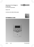
Installation sequence
Overview of electrical connections
T4A
250 V
R1
R2
A
E
P = 2 VA
AC 250 V 0,8 A
AC 250 V 4(2) A
IP 20, l, T40 230 V
50 Hz
S1
1 2
S2
3 4
S3
5 6
B
PWM
+
9 10
145
11 12
C
D
GND
A Wiring chamber of the solar control
unit
B Sensor inputs
C PWM signal for the solar circuit
pump
N R2 N R1 N L
13 14 15 16 17 18 19 20 21
?
D KM BUS
E Fuse, 4.0 A (slow)
R1 Semiconductor relay (suitable for
speed control)
R2 Electromechanical relay
Solar circuit pump
Possible pumps
Standard solar circuit pumps
With individual
speed control
"RPM" = 1
"RPM" = 0
Pumps with PWM
input
Note
Use only solar
pumps, not heating
circuit pumps.
"RPM" = 0
■ WILO pumps:
"RPM" = 2
■ GRUNDFOS
pumps:
"RPM" = 3
5369 987 GB
Without individual
speed control
(with integral auxiliary capacitor)
High efficiency
pumps
36
Installation sequence
Solar circuit pump (cont.)
Installation
The circulation pump with connecting
cable is part of the Solar-Divicon pump
station.
Alternative pumps must be type-tested
and installed in accordance with the
manufacturer's details.
Separate installation and service
instructions
3-core cable with a cross-section of
0.75 mm2.
Rated current: 0.8 A
Note
Pumps that draw more than 190 W must
be connected via an additional relay
(coupler relay). Disable the speed control for this pump (see chapter "Speed
control").
Standard pump
A
M
1~
R1 Solar circuit pump
5369 987 GB
A Wiring chamber of the solar control
unit
37
Installation
Connection
Installation sequence
Solar circuit pump (cont.)
Pump with PWM input
A
M
1~
A
Wiring chamber of the solar
control unit
R1/PWM Solar circuit pump
Pump/valve at output R2
Installation
Pump and valve must be type-tested and
installed in accordance with manufacturer's details.
Connection
Rated current: max. 4(2) A
5369 987 GB
3-core cable with a cross-section of
0.75 mm2.
38
Installation sequence
Pump/valve at output R2 (cont.)
A
A Wiring chamber of the solar control
unit
B
Installation
M
1~
B Pump or valve
High limit safety cut-out
A high limit safety cut-out in the consumer is required when less than
40 litres cylinder volume is available per
m2 absorber area. This installation safely
prevents temperatures in excess of
90 °C in the consumer.
Note
For the Vitocell 100, observe the max.
collector area that can be connected.
Installation
Install the sensor of the high limit safety
cut-out inside the cylinder cap (Vitocell
300 accessory).
Cylinder cap installation instructions
Connection
5369 987 GB
3-core cable with a cross-section of
1.5 mm2.
39
Installation sequence
High limit safety cut-out (cont.)
C Solar circuit pump
D Junction box (on site)
A
D
M
1~
C
B
A Wiring chamber of the solar control
unit
B High limit safety cut-out
Temperature setting
Delivered condition: 120 °C
Requires adjustment to 95 °C
High limit safety cut-out installation instructions
Collector temperature sensor
Installation
Collector installation instructions
Connection
40
Note
Never route this lead immediately next to
230/400 V cables.
5369 987 GB
Connect the sensor to S1 (terminals 1
and 2).
Extension of the connecting lead:
2-core cable with a cross-section of
1.5 mm2.
Installation sequence
Cylinder temperature sensor
Installation
With the threaded elbow.
DHW cylinder installation instructions
Connection
Note
Never route this lead immediately next to
230/400 V cables.
Installation
Connect the sensor to S2 (terminals 3
and 4).
Extension of the connecting lead:
2-core cable with a cross-section of
1.5 mm2.
Temperature sensor
Installation
1.
2.
4.
5369 987 GB
3.
41
Installation sequence
Temperature sensor (cont.)
Note
Never wrap insulating tape around the
sensor.
Seal in the sensor well.
Connection
Connect the sensor to S3 (terminals 5
and 6).
Extension of the connecting lead:
2-core cable with a cross-section of
1.5 mm2.
Note
Never route this lead immediately next to
230/400 V cables.
Power supply
Regulations
Protect the power cable to the control
unit with an appropriate fuse/MCB.
5369 987 GB
Carry out the power supply connection
and all earthing measures (i.e. RCD circuit) in accordance with IEC 364, the
requirements of your local power supply
utility, VDE or national regulations.
42
Installation sequence
Power supply (cont.)
B
?
N
L
C
Danger
Incorrect core termination can
cause severe injuries and damage to the equipment.
Never interchange cores "L" and
"N":
L Terminal 21
N Terminal 20
5369 987 GB
A Solar control unit wiring chamber
B ON/OFF switch (on site)
C Mains voltage 230 V/50 Hz
43
Installation
Provide the power supply connection
(230 V~) via a two-pole mains isolator
(on-site).
Disconnect the system by means of a
device which simultaneously separates
all non-earthed conductors with at least
3 mm contact separation.
A
Commissioning
Switching the power ON
1. Check whether all electrical connections have been correctly made.
2. Check that the high limit safety cutout (if required) is connected.
4. Check the type of solar circuit pump
that is connected and set parameter
"RPM" accordingly (see pages 36
and 45).
3. Switch ON the power; the solar control unit then implements an initiation
phase.
The solar control unit is now in automatic mode.
Navigation through the menu
■ The display shows the collector temperature and the system scheme.
■ Key
Calling up the menu for setting the system parameters
The symbol line on the display shows
which keys to use to make adjustments and scans.
■ Flashing "SET"
Values can be changed
■ Key
Terminating an adjustment already
begun in the menu (the value reverts
to its previous setting)
■ OK key
Confirmation of the selection or value
change made in the menu
Note
After approx. 4 min, the display changes
to show the collector temperature, if no
further adjustments are made.
Selecting the system scheme
Press the following keys:
2. OK "SET" flashes.
1.
3.
for the required scheme.
4. OK to confirm.
44
5369 987 GB
"ANL 1" and the display will
show the respective scheme.
Commissioning
Selecting the system scheme (cont.)
System schemes, see from page 51.
Setting system parameters
Press the following keys:
3. OK
"SET" flashes.
1.
"ANL" and the display will
show the respective scheme.
4.
for the selected value.
2.
until the required parameter is
shown (see table on
page 49).
/
5. OK
to confirm.
4.
for the required setting.
Auto Control mode
On in (100%)
"Æ" and "Â" or "Ã" are
displayed and "¨"
flashes.
OFF OFF
"Æ" is shown and "¨"
flashes.
Resetting system parameters
If a different system scheme is selected,
all parameters are returned to their original state.
Press the following keys:
1.
"ANL" and the display will
show the respective scheme.
2.
Select "HND 1" or "HND 2".
HND 1 Relay 1
HND 2 Relay 2
3. OK
"SET" flashes.
/
5369 987 GB
5. OK
to confirm.
6. After the relay test has been completed, select "Auto".
45
Service
Carrying out a relay test
Service scans
Scanning temperatures and operating conditions
Subject to system configuration and settings made, the following values can be
scanned with keys / :
Display
KOL
TSPU
S3
n1
n2
hP1
hP2
kWh
MWh
Description
°C Collector temperature
°C DHW temperature
°C Temperature at a sensor S3 that may be
connected
% Relative speed of the solar circuit pump
Status of relay R2:
OFF: Relay off
On: Relay on
h Hours run of the device at output relay R1
(solar circuit pump)
h Hours run of the device at output relay
R2
Amount of heat if a heat meter is enabled
Note
Add the values for MWh and kWh
together.
Resetting the hours run and the
energy volume
2. OK to confirm.
Whilst this value is displayed, press the
following keys:
5369 987 GB
1. OK "SET" flashes; value 0 is displayed.
46
Troubleshooting
Fault messages
Possible displays:
–88.8 Sensor short circuit
888.8 Sensor break
Sensor faults:
■ Display background light flashes
■ The sensor symbol in the system
scheme flashes quickly
■ ¨ flashes
Note
Further scans can be carried out with
keys / .
Example - collector temperature sensor short circuit
KOL
°C
Checking sensors
1000
100
1
B
0.1
-20
0
20 25
Temperature in °C
40
5369 987 GB
A Resistor 20 kΩ (sensor S1, collector
temperature sensor)
60
80
100
Service
Resistance in kΩ
10
A
120
140
B Resistor 10 kΩ (sensors S2 and
S3)
1. Disconnect the respective sensor
and measure its resistance.
47
Troubleshooting
Checking sensors (cont.)
2. Compare the measurement with the
actual temperature (for scanning see
page 46). Check the installation and,
in case of severe deviation, replace
the sensor.
Specification
Sensor NTC
Protection
Permissible ambient
temperature
■ during operation
■ during storage and
transport
10 kΩ at 25 °C
IP 53
20 kΩ at 25 °C
IP 53
−20 to + 90 °C
−20 to + 70 °C
−20 to + 200 °C
−20 to + 70 °C
Changing the fuse
A
B
A Solar control unit wiring chamber
B Fuse, 4 A (slow)
5369 987 GB
Open the solar control unit wiring chamber.
A spare fuse is included in the fuse
holder.
48
Function description
5369 987 GB
The following parameters can be set subject to the actual system configuration:
Display Parameters
Delivered Setting range System
condition
scheme
ANL
System scheme
1
1–10
—
DT E
Start temperature differen8K
1.5 – 20 K
tial for solar circuit
pump R1
DT A
Stop temperature differen4K
1.0 – 19.5 K
1 to 9
tial for solar circuit
pump R1
S SL
Set cylinder temperature
60 °C
4 – 90 °C
(see page 53)
DT 1E
Start temperature differen8K
1.5 – 20 K
tial for solar circuit pump R1
(consumer 1)
DT 1A
Stop temperature differen4K
1.0 – 19.5 K
tial for solar circuit pump R1
(consumer 1)
S 1SL
Set cylinder temperature
60 °C
4 – 90 °C
(consumer 1)
(see page 53)
10
DT 2E
Start temperature differen8K
1.5 – 20 K
tial for solar circuit pump R1
and valve R2 (consumer 2)
DT 2A
Stop temperature differen4K
1.0 – 19.5 K
tial for solar circuit pump R1
and valve R2 (consumer 2)
S 2SL
Set cylinder temperature
60 °C
4 – 90 °C
(consumer 2)
(see page 53)
NOT
Collector limit temperature
130 °C
110 – 200 °C
(see page 62)
OKX
Collector cooling function
OFF
OFF/ON
(maximum collector temperKMX
110 °C
90 – 190 °C
ature limit)
(see page 62)
1 to 10
OKN
Minimum collector temperaOFF
OFF/ON
ture limit
KMN
10 °C
10 – 90 °C
(see page 62)
OKF
Frost protection
OFF
OFF/ON
(see page 63)
KFR
4 °C
−10 – +10 °C
49
Service
Parameter overview
Function description
Parameter overview (cont.)
PRIO
tSP
tUMW
ORUE
ORK
DT 3E
DT 3A
MX3E
MX3A
MN3E
MN3A
NH E
NH A
OWMZ
VMAX
at 100%
pump
speed
MEDT
MED%
RPM
n1MN*1
*1
Parameters
Delivered Setting range System
condition
scheme
Sequence in which the con1
0–2
sumers are heated up
10
Pump run break duration,
2 min
1 – 30 min
cycle pause time
Break intervals
15 min
1 – 30 min
Return cooling function
OFF
OFF/ON
(see page 63)
1 to 10
Interval function
OFF
OFF/ON
(see page 63)
Start temperature differen8K
0 – 20 K
tial for anti-stratification
pump R2
Stop temperature differen4K
0.5 – 19.5 K
tial for anti-stratification
7
pump R2
Maximum limit S3 on
58 °C
0 – 94.5 °C
Maximum limit S3 off
60 °C
0.5 – 95 °C
Minimum limit S3 on
10 °C
0.5 – 90 °C
Minimum limit S3 off
5 °C
0 – 89.5 °C
Starting temperature for the
40 °C
0 – 89.5 °C
3, 5, 9
thermostat function
Switch-off temperature for
45 °C
0.5 – 90 °C
3, 5, 9
the thermostat function
Heat statement
OFF
OFF/ON
(see page 64)
5.0 l/min
0.1 – 20 l/min
Speed control
(see page 64)
Minimum speed
(see page 64)
Only adjustable with setting RPM > 0.
50
3
40
0
0–3
20 – 70
0–3
30 %
30/20 – 100 %
1 to 10
5369 987 GB
Display
Function description
Parameter overview (cont.)
Parameters
DT S*1
Differential temperature for
the start of the speed regulation
(see page 64)
Rise
(see page 64)
Differential temperature for
the start of speed regulation
(consumer 1)
(see page 64)
Rise (consumer 1)
(see page 64)
Differential temperature for
the start of speed regulation
(consumer 2)
(see page 64)
Rise (consumer 2)
(see page 64)
Manual mode relay 1
(see page 45)
Manual mode relay 2
(see page 45)
Software version of the solar
control unit
Hardware version
ANS*1
DT 1S*1
ANS1*1
DT 2S*1
ANS2*1
HND1
HND2
PROG
VERS
Delivered Setting range System
condition
scheme
10 K
0.5 – 30 K
1 to 9
2K
1 – 20 K
10 K
0.5 – 30 K
2K
1 – 20 K
10 K
0.5 – 30K
2K
1 – 20 K
AUTO
OFF/ON
AUTO
OFF/ON
—
—
—
—
—
—
10
1 to 10
System scheme
5369 987 GB
10 system schemes can be achieved
with the solar control unit. Selection via
parameter "ANL" (see page 44). All system schemes include the "ANL 1" functions (system scheme 1):
*1
■ Dual-mode DHW heating
■ Suppression of reheating by the boiler
in conjunction with control units with
KM BUS
■ Maximum DHW cylinder temperature
limit
Only adjustable with setting RPM > 0.
51
Service
Display
Function description
System scheme (cont.)
■ Frost protection function (see
page 63)
■ Reverse cooling function (see
page 63)
■ Interval function (see page 63)
■ Heat statement (see page 64)
■ Speed control (see page 64)
5369 987 GB
Auxiliary functions can be enabled for
every system scheme.
■ Collector limit temperature (see
page 62)
■ Collector cooling function (see
page 62)
■ Collector minimum temperature limit
(see page 62)
52
Function description
System scheme (cont.)
Dual-mode DHW heating with suppression of reheating by the boiler in conjunction with control units with KM BUS
Display
Temperature differential control
Determination of the temperature differential between collector temperature sensor S1 and cylinder temperature
sensor S2.
■ Solar circuit pump R1 on:
Exceeding "DT E"
■ Solar circuit pump R1 off:
The actual temperature falls below the switch-off temperature differential "DT A"
Cylinder temperature limit
Solar circuit pump R1 off:
When reaching the set cylinder temperature "S SL".
Symbol "È" is shown.
Suppression of reheating by the boiler in conjunction
with control units with KM BUS
■ Function enabled:
– The DHW cylinder is heated by the solar thermal system.
– Connection of the KM BUS to terminals 11 and 12 in
the solar control unit.
■ In the boiler control unit, coding address "67" defaults a
third set DHW temperature.
(This value must be below the first set DHW temperature).
See the installation and service instructions of the boiler
control unit.
■ The DHW cylinder will only be heated by the boiler, if this
set value cannot be achieved by the solar thermal system.
5369 987 GB
Note
In some boiler control units, the PCB must be replaced (see
page 68).
53
Service
"ANL" = 1— Standard scheme
Function description
System scheme (cont.)
"ANL" = 2
Dual-mode DHW heating with suppression of reheating by the boiler in conjunction with control units without KM BUS and/or control of the secondary
pump of an external heat exchanger
Display
Suppression of reheating by the boiler in conjunction
with control units without KM BUS
■ Function enabled:
– The DHW cylinder is heated by the solar thermal system.
– A resistor simulates an actual DHW temperature that
is 10 K higher (for connections, see the following
table).
■ The DHW cylinder will only be heated by the boiler, if the
set DHW temperature cannot be achieved by the solar
thermal system.
System with an external heat exchanger
S1
R1
S2
R2
5369 987 GB
The secondary pump R2 is started in parallel with the solar
circuit pump.
54
Function description
System scheme (cont.)
Cylinder temperature sensor as PTC
IP 20, l, T40
A
230 V
50 Hz
N R2 N R1 N L
13 14 15 16 17 18 19 20 21
?
Cylinder temperature sensor as NTC
50 Hz
N R2 N R1 N L
13 14 15 16 17 18 19 20 21
?
B
B
C
C
D
D
E
E
Resistor 20 Ω, 0.25 W (on-site)
C Resistor 10 kΩ, 0.25 W (on-site)
Solar control unit wiring chamber
Contactor relay
To the boiler control unit; connection for cylinder temperature sensor
Cylinder temperature sensor of the boiler control unit
5369 987 GB
Service
C
A
B
E
D
IP 20, l, T40 230 V
A
55
Function description
System scheme (cont.)
"ANL" = 3
Dual-mode DHW heating and thermostat function
Display
Thermostat function
Output R2 is used for this function.
Relay R2 switches subject to the temperature at S3 (see
the following table).
Different effects can be achieved by determining the start and stop temperatures:
"NH E" < "NH A"
"NH E" > "NH A"
e.g. for reheating
e.g. for utilising excess heat
Thoff
Thon
Thon
Thoff
R2on
R2off
R2on
R2off
"ANL" = 4
Dual-mode DHW heating and auxiliary function
Display
Auxiliary function for DHW heating
■ Connection of the anti-stratification pump at R2.
■ Signal for starting the anti-stratification pump R2 via the
KM BUS of the boiler control unit. This also heats the
lower area of the DHW cylinder to the required temperature.
5369 987 GB
Note
In some boiler control units, the PCB must be replaced (see
page 68).
56
Function description
System scheme (cont.)
1. Connect the KM BUS at terminals 11
and 12 in the solar control unit.
2. Program the second set DHW temperature at the boiler control unit.
Installation and service
instructions; boiler control
unit
Danger
DHW with temperatures in
excess of 60 °C can cause scalding.
To limit the temperature to 60 °C,
install mixing equipment, e.g. a
thermostatically controlled mixing valve (accessory). Install a
mixer tap as anti-scalding device
at the draw-off point.
3. Adjust the fourth DHW phase at the
boiler control unit.
Operating instructions, boiler
control unit
"ANL" = 5
5369 987 GB
Service
Dual-mode DHW heating, thermostat function and auxiliary function
Display
Output R2 enables the thermostat function (see page 56)
and the auxiliary function (see page 56) to be achieved.
57
Function description
System scheme (cont.)
"ANL" = 6
Dual-mode DHW heating and maximum cylinder temperature control
Display
■ When exceeding the set cylinder temperature
"S SL" (see page 53) the anti-stratification pump R2 will
start.
■ Excess heat is transferred, e.g. to the pre-heating stage.
"ANL" = 7
Dual-mode DHW heating and anti-stratification
Display
Determination of the temperature differential between collector temperature sensor S2 and cylinder temperature
sensor S3.
■ Anti-stratification pump R2 on:
Exceeding "DT 3E"
■ Anti-stratification pump R2 off:
The actual temperature falls below the stop temperature
differential "DT 3A"
"ANL" = 8
5369 987 GB
Dual-mode DHW heating, auxiliary function and anti-stratification with sensor
S3 in DHW cylinder 2 (existing)
Display
The anti-stratification pump R2 circulates the heating water
to prevent stratification (see page 58) and implements the
auxiliary function (see page 56).
58
Function description
System scheme (cont.)
"ANL" = 9
5369 987 GB
Service
Dual-mode DHW heating, auxiliary function and anti-stratification with sensor
S3 in DHW cylinder 1 (retrofit)
Display
The anti-stratification pump R2 circulates the heating water
to prevent stratification (see page 58) and implements the
auxiliary function (see page 56).
59
Function description
System scheme (cont.)
"ANL" = 10
5369 987 GB
Dual-mode DHW heating, heating of consumer 2 via the three-way diverter
valve
Display
Temperature differential control
Determination of the temperature differential between collector temperature sensor S1 and cylinder temperature
sensor S2.
■ Solar circuit pump R1 on:
Exceeding "DT 1E"
Consumer 1 is being heated.
■ Solar circuit pump R1 off:
The actual temperature falls below the stop temperature
differential "DT 1A"
Determination of the temperature differential between collector temperature sensor S1 and cylinder temperature
sensor S3.
■ Solar circuit pump R1 and three-way diverter valve R2
on:
Exceeding "DT 2E"
Consumer 2 is being heated.
■ Solar circuit pump R1 and three-way diverter valve R2
off:
The actual temperature falls below the stop temperature
differential "DT 2A"
Cyclical heating
■ If the DHW cylinder cannot be heated with priority
("PRIO" 1), the next consumer in line will be heated for
an adjustable cycle time "tUMW".
■ After expiry of this time, the solar control unit checks the
temperature rise at the collector during the cycle pause
time "tSP".
■ As soon as the start conditions for the consumer with
priority ("PRIO" 1) have been met, that consumer will be
heated again. Otherwise, the consumer with lower ranking will continue to be heated.
■ Once the consumer with priority has reached its set temperature "S SL", no cyclical heating will be implemented.
60
Function description
System scheme (cont.)
Consumer 1
Parameters
DT 1E
DT 1A
S1 SL
Delivered condition
8.0 K
4.0 K
60 °C
Setting range
1.5 – 20.0 K
1.0 – 19.5 K
4 – 90 °C
8.0 K
4.0 K
60 °C
Setting range
1.5 – 20.0 K
1.0 – 19.5 K
4 – 90 °C
Note
"DT 1E" can be set at least 0.5 K higher
than "DT 1A".
"DT 1A/" can be set at least 0.5 K lower
than "DT 1E".
Consumer 2
Parameters
DT 2E
DT 2A
S2 SL
Delivered condition
Note
"DT 2E" can be set at least 0.5 K higher
than "DT 2A".
"DT 2A" can be set at least 0.5 K lower
than "DT 2E".
Parameters
PRIO
tSP
tUMW
Delivered condition
Setting range
1
2 min
15
0–2
1 – 30 min
1 – 30 min
5369 987 GB
Service
0 Priority consumer 1, no cyclical heating
1 Priority consumer 1, with cyclical
heating
2 Priority consumer 2, with cyclical
heating
61
Function description
Collector limit temperature
The solar circuit pump is switched OFF
to protect the system components if the
"NOT" temperature has been exceeded;
the symbol "¨" flashes.
Setting parameters
NOT
Set value for "NOT" (see page 45).
Delivered condition
130 °C
Setting range
110 – 200 °C
Note
This function is disabled at setting
200 °C.
Collector cooling function
The solar circuit pump will be switched
off when the set cylinder temperature
"S SL" is reached.
If the collector temperature rises to the
set maximum collector temperature
"KMX", the pump will be switched ON
long enough to enable this temperature
to fall 5 K lower (the symbol "È" flashes).
The cylinder temperature can then rise
again, but only up to 90 °C; at that point,
the solar circuit pump is switched off (the
symbol "¨" flashes).
Setting parameters
KMX
1. Set "OKX" to "ON" (see page 45).
2. Select the "KMX" value.
Delivered condition
110 °C
Setting range
90 – 190 °C
Minimum collector temperature limit
The pump is switched OFF, if the actual
temperature falls 5 K below this temperature; symbol "e" flashes.
1. Set "OKN" to "ON" (see page 45).
2. Select the "KMN" value.
62
5369 987 GB
Minimum starting temperature "KMN"
that must be exceeded before the solar
circuit pump can start.
This prevents the pump starting too frequently (cycling).
Function description
Minimum collector temperature limit (cont.)
Setting parameters
KMN
Delivered condition
10 °C
Setting range
10 – 90 °C
Frost protection function
Enable this function only when using
water as heat transfer medium.
The solar circuit pump will be switched
ON to avoid collector damage, if the collector temperature falls below the
"KFR" value.
The symbol "e" is displayed if this function is enabled and flashes if the solar
circuit pump is running.
Setting parameters
KFR
1. Set "OKF" to "ON" (see page 45).
2. Select the "KFR" value.
Delivered condition
4 °C
Setting range
−10 – +10 °C
Reverse cooling function
In the evening, the pump will continue to
run (symbol "È" flashes) until the DHW
cylinder has been cooled down via the
collector and the pipework to the set cylinder temperature "S SL".
Set "ORUE" to "ON" (see page 45).
Service
Enable only in systems with flat-plate
collectors.
The "ORUE" function only makes sense
if the collector cooling function has been
enabled (see page 62).
The collector cooling function enables
the heating of the DHW cylinder to a
higher temperature than "S SL" (see
page 53).
5369 987 GB
Interval function
Activate the interval function in systems
where the collector temperature sensor
is not in an ideal location to prevent a
time delay in capturing the collector temperature.
For this, the solar circuit pump is started
for 30 s when the collector temperature
rises by 2 K.
Set "ORK" to "ON" (see page 45).
63
Function description
Heat statement
The heat statement is calculated from
the temperature differential between the
collector and cylinder temperature as
well as the selected throughput (see
service instructions "Vitosol").
3. Adjusting the frost protection of the
heat transfer medium "MEDT".
4. If necessary, adjust the mixing ratio
of the heat transfer medium "MED
%".
1. Set "OWMZ" to "ON" (see
page 45).
2. Check the throughput at the flow
meter of the Solar-Divicon at 100 %
speed and set that value as
"VMAX".
MEDT setting
0
1
2
3
Heat transfer medium
Water
Propylene glycol
Ethylene glycol
Viessmann heat transfer medium
Setting parameters
VMAX
MEDT
MED %
Delivered condition
Setting range
5.0 l/min
3
40 %
0.1 – 20 l/min
0–3
20 – 70 %
Speed control
Speed control is disabled at the factory
("RPM" set to 0, see page 45). It can
only be enabled for relay output R1
(solar circuit pump).
The solar circuit pump should not have
its own speed control. Set multi-stage
pumps to the required stage.
The solar circuit pump will be switched
ON, if "DT E" has been exceeded.
If the temperature differential rises to
"DT S" (differential temperature for the
start of the speed control), then the
speed is increased by 10% with every
rise by the value selected in "ANS"
(rise).
5369 987 GB
Note
When using pumps with their own variable speed control, set "RPM" to 0.
64
Function description
Speed control (cont.)
Setting parameters
n1MN
DT S
ANS
Delivered condition
30 %
10 K
2K
Setting range
30 – 100 %
0.5 – 30 K
1 – 20 K
Speed in %
Example
60
50
40
30
20
10
0
0 2 4 6 8 10 12 14
Temperature differential in K
DT E =8 K
DT S =10 K
ANS =2 K
Enabling speed control
5369 987 GB
Service
Set the required value for "RPM" (see
page 45).
1 Standard solar circuit pumps (with
integral auxiliary capacitor)
2 WILO pump with PWM input
3 GRUNDFOS pump with PWM input
65
Parts list
Parts list
When ordering spare parts
Quote the part and serial no. (see type
plate) and the position no. of the required
part (as per this parts list).
Obtain standard parts from your local
supplier.
030 Strain relief pack, capacitor and
fuse
040 Fuse, 4 A (slow)
050 Installation and service instructions
060 Operating instructions
5369 987 GB
Parts
010 Collector temperature sensor
020 Cylinder temperature sensor
66
Specification
204
Specification
170
Rated voltage
Rated frequency
Rated current
Power consumption
Protection class
Protection
47
230 V~
50 Hz
4 A∼
2W
(in standby mode 0.7 W)
II
IP 20 D to EN 60529, ensure through design/installation
Type 1 B to EN 60730-1
Function
Permiss. ambient temperature
■ during operation
0 to +40 °C
Installation in living spaces or boiler rooms (standard ambient conditions)
■ during storage and transport -20 to +65 °C
5369 987 GB
Service
Rated breaking capacity of the relay
outputs at 230 V~:
■ R1
0.8 A∼
■ R2
4 (2) A ∼
67
Appendix
Appendix
Replace the PCB in the stated boiler
control units in conjunction with the following functions:
■ Suppression of reheating by the boiler
■ Auxiliary function for DHW heating,
achieved by the solar control unit
Electronics PCB
Part no. 7828 192
part no. 7828 193
Part no. 7824 030
5369 987 GB
Control unit
Vitotronic 200, type KW1,
part no. 7450 351, 7450 740
Vitotronic 200, type KW2,
part no. 7450 352, 7450 750
Vitotronic 300, type KW3,
part no. 7450 353, 7450 760
Vitotronic 200, type GW1,
part no. 7143 006
Vitotronic 300, type GW2,
Part no. 7143 156
Vitotronic 333, type MW1,
Part no. 7143 421
68
Certificates
Declaration of conformity
We, Viessmann Werke GmbH & Co KG, D-35107 Allendorf, confirm as sole responsible body that the product Vitosolic 100 complies with the following standards:
EN 55 014-1
EN 60 730
This product is designated _ in accordance with the following Directives:
2004/108/EC
2006/95/EC
Allendorf, 1 April 2009
Viessmann Werke GmbH&Co KG
5369 987 GB
Service
pp. Manfred Sommer
69
Keyword index
Keyword index
A
Anti-scalding protection..................6, 57
Anti-stratification................................58
Applicability........................................72
Automatic mode...........................44, 45
Auxiliary function for DHW heating....56
Maximum cylinder temperature
control................................................58
Minimum collector temperature limit. .62
C
Changing settings..............................45
Changing the fuse..............................48
Changing values................................45
Checking sensors..............................47
Collector cooling function...................62
Collector limit temperature.................62
Collector temperature sensor.............40
Commissioning..................................44
Cyclical heating..................................60
Cylinder temperature limit..................53
Cylinder temperature sensor..............41
O
Operating steps..................................44
Overview of electrical connections.....36
E
External heat exchanger....................54
F
Fault messages..................................47
Fitting the solar control unit................35
Frost protection function....................63
H
Hardware version...............................51
Heat statement...................................64
High limit safety cut-out......................39
I
Interval function..................................63
M
Manual mode.....................................45
Manual operation...............................45
Maximum collector temperature limit. 62
70
P
Parts list.............................................66
Power supply.....................................42
Pump at R2........................................38
Pumps................................................36
R
Relay test...........................................45
Restoring the delivered condition.......45
Reverse cooling function....................63
S
Scanning temperatures......................46
Selecting the system scheme............44
Setting system parameters................45
Software version of the solar control
unit.....................................................51
Solar circuit pump..............................36
Spare fuse..........................................48
Speed control.....................................64
Starting the solar control unit.............44
Suppressing reheating
■ Control units with KM BUS.............53
■ Control units without KM BUS........54
Switching the power ON....................44
T
Temperature differential control...53, 60
Temperature sensor...........................41
Thermostat function...........................56
5369 987 GB
D
Declaration of conformity...................69
N
Navigation through the menu.............44
Keyword index
Keyword index (cont.)
5369 987 GB
V
Valve at R2........................................38
71
72
Viessmann Limited
Hortonwood 30, Telford
Shropshire, TF1 7YP, GB
Telephone: +44 1952 675000
Fax: +44 1952 675040
E-mail: [email protected]
chlorine-free bleached paper
Printed on environmentally friendly,
Viessmann Werke GmbH&Co KG
D-35107 Allendorf
Telephone: +49 6452 70-0
Fax: +49 6452 70-2780
www.viessmann.com
Subject to technical modifications.
Applicable for the Vitosolic 100, type SD1
Part no. 7418 199
5369 987 GB
Applicability