1
Order no. 6515 3564 13 Part no. 212 584 51 00 Edition B 2014
E-Class Sedan and Wagon Operator's Manual
É2125845100{ËÍ
2125845100
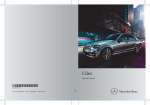
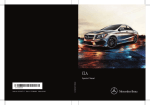
E-Class
Sedan and Wagon
Operator's Manual
Symbols
Registered trademarks:
i Practical tips or further information that
RBluetooth®
X
is a registered trademark of
Bluetooth SIG Inc.
RDTS is a registered trademark of DTS, Inc.
RDolby and MLP are registered trademarks
of DOLBY Laboratories.
RBabySmart™, ESP® and PRE-SAFE® are
registered trademarks of Daimler AG.
RHomeLink® is a registered trademark of
Johnson Controls.
RiPod® and iTunes® are registered
trademarks of Apple Inc.
RLogic7® is a registered trademark of
Harman International Industries.
RMicrosoft® and Windows media® are
registered trademarks of Microsoft
Corporation.
RSIRIUS is a registered trademark of Sirius
XM Radio Inc.
RHD Radio is a registered trademark of
iBiquity Digital Corporation.
RGracenote® is a registered trademark of
Gracenote, Inc.
RZAGATSurvey® and related brands are
registered trademarks of ZagatSurvey,
LLC.
In this Operator's Manual you will find the
following symbols:
could be helpful to you.
This symbol indicates an
instruction that must be followed.
Several of these symbols in
X
succession indicate an instruction
with several steps.
(Y page) This symbol tells you where you
can find more information about a
topic.
This symbol indicates a warning or
YY
an instruction that is continued on
the next page.
Display This font indicates a display in the
multifunction display/COMAND
display.
Publication details
Internet
Further information about Mercedes-Benz
vehicles and about Daimler AG can be found
on the following websites:
http://www.mbusa.com (USA only)
http://www.mercedes-benz.ca (Canada
only)
Editorial office
©Daimler
AG: Not to be reprinted, translated
or otherwise reproduced, in whole or in part,
without written permission from Daimler AG.
Parts of the software in the vehicle are
protected by copyright © 2005
The FreeType Project
http://www.freetype.org. All rights
reserved.
G WARNING
Warning notes draw your attention to hazards
that endanger your health or life, or the health
or life of others.
H Environmental note
Environmental notes provide you with
information on environmentally aware actions
or disposal.
! Notes on material damage alert you to
dangers that could lead to damage to your
vehicle.
As at 22.11.2012
Welcome to the world of Mercedes-Benz
We urge you to read this Operator's Manual
carefully and familiarize yourself with the
vehicle before driving. For your own safety
and a longer vehicle life, follow the
instructions and warning notices in this
manual. Ignoring them could result in damage
to the vehicle or personal injury to you or
others.
Vehicle damage caused by failure to follow
instructions is not covered by the MercedesBenz Limited Warranty.
The equipment or product designation of your
vehicle may vary depending on:
RModel
ROrder
RCountry
specification
RAvailability
Mercedes-Benz therefore reserves the right
to introduce changes in the following areas:
RDesign
REquipment
RTechnical
features
The equipment in your vehicle may therefore
differ from that shown in the descriptions and
illustrations.
The following are integral components of the
vehicle:
ROperator's
Manual
Booklet
REquipment-dependent supplements
Keep printed copies of the documents in the
vehicle at all times. If you sell the vehicle,
always pass the documents on to the new
owner.
The technical documentation team at
Daimler AG wishes you safe and pleasant
motoring.
Mercedes-Benz USA, LLC
Mercedes-Benz Canada, Inc.
A Daimler Company
RMaintenance
2125845100 É2125845100{ËÍ
Contents
Index ....................................................... 4
At a glance ........................................... 29
Introduction ......................................... 22
Safety ................................................... 39
Opening and closing ........................... 81
Seats, steering wheel and mirrors . . 107
Lights and windshield wipers .......... 127
Climate control ................................. 143
Driving and parking .......................... 157
On-board computer and displays .... 237
Stowage and features ...................... 297
Maintenance and care ...................... 335
Breakdown assistance ..................... 351
Wheels and tires ............................... 371
Technical data ................................... 415
3
4
Index
1, 2, 3 ...
115 V socket ......................................
12 V socket
see Sockets
360° camera
Cleaning .........................................
Function/notes .............................
4ETS
see ETS/4ETS (Electronic
Traction System)
4MATIC (permanent four-wheel
drive) ..................................................
321
346
220
208
A
ABS (Anti-lock Braking System)
Display message ............................ 258
Function/notes ................................ 67
Important safety notes .................... 67
Warning lamp ................................. 288
Activating/deactivating cooling
with air dehumidification ................. 149
Active Blind Spot Assist
Activating/deactivating (onboard computer) ............................ 248
Display message ............................ 276
Function/information .................... 230
Active Driving Assistance package . 230
Active Lane Keeping Assist
Activating/deactivating (onboard computer) ............................ 248
Display message ............................ 275
Function/information .................... 233
Active light function ......................... 133
Active multicontour seat
Adjusting (on the seat) .................. 113
Active Parking Assist
Detecting parking spaces .............. 213
Display message ............................ 276
Exiting a parking space .................. 215
Function/notes ............................. 212
Important safety notes .................. 212
Parking .......................................... 214
ADAPTIVE BRAKE ................................. 75
Adaptive Brake Assist
Function/notes ................................ 71
Adaptive Damping System (ADS) ..... 205
Adaptive Highbeam Assist
Display message ............................ 269
Function/notes ............................. 133
Switching on/off ........................... 134
Additives (engine oil) ........................ 422
Air bags
Display message ............................ 265
Front air bag (driver, front
passenger) ....................................... 44
Important safety notes .................... 42
Knee bag .......................................... 45
PASSENGER AIR BAG OFF
indicator lamp .................................. 48
Pelvis air bag ................................... 46
Safety guidelines ............................. 41
Side impact air bag .......................... 45
Window curtain air bag .................... 47
Air-conditioning system
see Climate control
Air filter (display message) .............. 272
AIRMATIC
Display message ............................ 273
Function/notes ............................. 204
Air vents
Glove box ....................................... 156
Important safety notes .................. 155
Rear ............................................... 156
Setting ........................................... 155
Setting the center air vents ........... 155
Setting the side air vents ............... 155
Alarm system
see ATA (Anti-Theft Alarm system)
Ambient lighting
Setting the brightness (on-board
computer) ...................................... 250
Setting the color (on-board
computer) ...................................... 250
AMG adaptive sport suspension
system ................................................ 206
Anti-lock braking system
see ABS (Anti-lock Braking System)
Anti-theft alarm system
see ATA (Anti-Theft Alarm system)
Ashtray ............................................... 318
Assistance display (on-board
computer) .......................................... 246
Index
Assistance menu (on-board
computer) .......................................... 246
ASSYST PLUS
Displaying a service message ........ 341
Hiding a service message .............. 341
Notes ............................................. 340
Resetting the service interval
display ........................................... 341
Service message ............................ 340
Special service requirements ......... 341
ATA (Anti-Theft Alarm system)
Activating/deactivating ................... 78
Function ........................................... 78
Switching off the alarm .................... 78
ATTENTION ASSIST
Activating/deactivating ................. 248
Display message ............................ 273
Function/notes ............................. 225
Audio system
see separate operating instructions
Authorized Centers
see Qualified specialist workshop
Authorized Mercedes-Benz Center
see Qualified specialist workshop
Authorized workshops
see Qualified specialist workshop
AUTO lights
Display message ............................ 269
see Lights
Automatic engine start (ECO start/
stop function) .................................... 164
Automatic engine switch-off (ECO
start/stop function) .......................... 163
Automatic headlamp mode .............. 129
Automatic transmission
Automatic drive program ............... 172
Changing gear ............................... 170
DIRECT SELECT lever ..................... 168
Display message ............................ 282
Drive program display .................... 168
Driving tips .................................... 170
Emergency running mode .............. 175
Engaging drive position .................. 170
Engaging neutral ............................ 169
Engaging park position (AMG
vehicles) ........................................ 169
Engaging reverse gear ................... 169
Engaging the park position ............ 168
Kickdown .......................................
Manual drive program ....................
Manual drive program (AMG
vehicles) ........................................
Overview ........................................
Problem (malfunction) ...................
Program selector button ................
Pulling away ...................................
Selector lever ................................
Starting the engine ........................
Steering wheel paddle shifters ......
Transmission position display ........
Transmission position display
(DIRECT SELECT lever) ...................
Transmission positions ..................
Automatic transmission
emergency mode ...............................
171
172
173
167
175
171
162
167
161
172
167
168
170
175
B
Bag hook ............................................ 306
BAS (Brake Assist System) ................. 68
BAS PLUS (Brake Assist System
PLUS) with Cross-Traffic Assist
Function/notes ................................ 68
BAS PLUS Q (Brake Assist System
PLUS) with Cross-Traffic Assist
Important safety notes .................... 69
Battery (SmartKey)
Checking .......................................... 85
Important safety notes .................... 85
Replacing ......................................... 85
Battery (vehicle)
Charging ........................................ 360
Display message ............................ 271
Important safety notes .................. 358
Jump starting ................................. 362
Belt force limiter
Activation ......................................... 59
Function ........................................... 59
Blind Spot Assist
Activating/deactivating ................. 248
Display message ............................ 276
Notes/function .............................. 226
see Active Blind Spot Assist
BlueTEC
Adding DEF .................................... 180
BlueTEC (DEF) .................................... 421
5
6
Index
Bottle holder ...................................... 316
Box (trunk) ......................................... 309
Brake Assist
see BAS (Brake Assist System)
Brake fluid
Display message ............................ 260
Notes ............................................. 423
Brake lamps
Display message ............................ 267
Brakes
ABS .................................................. 67
Adaptive Brake Assist ...................... 71
BAS .................................................. 68
BAS PLUS with Cross-Traffic Assist . 68
Brake fluid (notes) ......................... 423
Display message ............................ 258
Driving tips .................................... 186
High-performance brake system .... 187
HOLD function ............................... 202
Important safety notes .................. 186
Maintenance .................................. 187
Parking brake ................................ 183
Warning lamp ................................. 287
Breakdown
see Flat tire
Bulbs
see Replacing bulbs
C
California
Important notice for retail
customers and lessees .................... 24
Calling up a malfunction
see Display messages
Car
see Vehicle
Care
360° camera ................................. 346
Carpets .......................................... 349
Car wash ........................................ 342
Display ........................................... 347
Exhaust pipe .................................. 347
Exterior lights ................................ 345
Gear or selector lever .................... 347
Interior ........................................... 347
Matte finish ................................... 344
Notes ............................................. 341
Paint .............................................. 344
Plastic trim .................................... 347
Power washer ................................ 343
Rear view camera .......................... 346
Roof lining ...................................... 349
Seat belt ........................................ 348
Seat cover ..................................... 348
Sensors ......................................... 346
Steering wheel ............................... 347
Trim pieces .................................... 348
Washing by hand ........................... 343
Wheels ........................................... 344
Windows ........................................ 345
Wiper blades .................................. 345
Wooden trim .................................. 348
Cargo compartment cover ............... 307
Cargo compartment enlargement . . . 304
Cargo compartment floor ................. 313
Cargo net
Attaching ....................................... 309
Important safety information ......... 309
Cargo tie down rings ......................... 306
Car keys
see SmartKey
Car wash (care) ................................. 342
CD player/CD changer (on-board
computer) .......................................... 244
Center console
Lower section .................................. 35
Lower section (AMG vehicles) .......... 36
Upper section .................................. 34
Central locking
Automatic locking (on-board
computer) ...................................... 251
Locking/unlocking (SmartKey) ........ 82
Changing bulbs
High-beam headlamps ................... 137
Turn signals (front) ......................... 138
Child-proof locks
Important safety notes .................... 65
Rear doors ....................................... 66
Children
In the vehicle ................................... 60
Restraint systems ............................ 60
Special seat belt retractor ............... 63
Index
Child seat
LATCH-type (ISOFIX) child seat
anchors ............................................ 63
Top Tether ....................................... 64
Cigarette lighter ................................ 319
Cleaning
Mirror turn signal ........................... 345
Climate control
Automatic climate control (3-zone) 147
Controlling automatically ............... 150
Cooling with air dehumidification . . 149
Defrosting the windows ................. 153
Defrosting the windshield .............. 152
Dual-zone automatic climate
control ........................................... 145
Important safety notes .................. 144
Indicator lamp ................................ 150
Information about using dual-zone
automatic climate control .............. 146
Information on using dual-zone
automatic climate control .............. 148
Maximum cooling .......................... 153
Overview of systems ...................... 144
Problems with cooling with air
dehumidification ............................ 150
Problem with the rear window
defroster ........................................ 154
Rear control panel ......................... 147
Refrigerant ..................................... 425
Refrigerant filling capacity ............. 425
Setting the air distribution ............. 151
Setting the airflow ......................... 152
Setting the air vents ...................... 155
Setting the climate mode ............... 150
Setting the temperature ................ 151
Setting the temperature with 3zone automatic climate control ..... 151
Setting the temperature with dualzone automatic climate control ..... 151
Switching air-recirculation mode
on/off ............................................ 154
Switching on/off ........................... 148
Switching residual heat on/off ...... 154
Switching the rear window
defroster on/off ............................ 153
Switching the ZONE function on/
off .................................................. 152
Coat hooks ......................................... 309
Cockpit
Overview .......................................... 30
see Instrument cluster
Collapsible spare wheel
Inflating ......................................... 412
see Emergency spare wheel
COLLISION PREVENTION ASSIST
Activating/deactivating the
distance warning function .............. 247
Display message ............................ 261
Operation/notes .............................. 70
COMAND
see separate operating instructions
COMAND display
Cleaning ......................................... 347
Combination switch .......................... 131
Combined cargo cover and net ........ 308
Consumption statistics (on-board
computer) .......................................... 241
Convenience box ............................... 309
Convenience closing feature .............. 99
Convenience opening feature ............ 99
Coolant (engine)
Checking the level ......................... 339
Display message ............................ 269
Filling capacity ............................... 424
Important safety notes .................. 423
Temperature (on-board computer) . 253
Temperature gauge ........................ 238
Warning lamp ................................. 293
Cooling
see Climate control
Copyright ............................................. 28
Cornering light function
Display message ............................ 266
Function/notes ............................. 133
Crash-responsive emergency
lighting ............................................... 136
Cruise control
Activation conditions ..................... 190
Cruise control lever ....................... 190
Deactivating ................................... 191
Display message ............................ 279
Driving system ............................... 189
Function/notes ............................. 189
Important safety notes .................. 189
7
8
Index
Setting a speed .............................. 191
Storing and maintaining current
speed ............................................. 190
Cup holder
Center console .............................. 316
Important safety notes .................. 316
Rear compartment ......................... 316
Customer Assistance Center (CAC) ... 27
Customer Relations Department ....... 27
D
Dashboard
see Instrument cluster
Dashboard lighting
see Instrument cluster lighting
Data
see Technical data
Daytime running lamps
Display message ............................ 268
Function/notes ............................. 129
Switching on/off (on-board
computer) ...................................... 250
Dealerships
see Qualified specialist workshop
Declarations of conformity ................. 26
DEF
Adding ........................................... 180
Display message ............................ 273
Filling capacity ............................... 422
Important safety notes .................. 421
Delayed switch-off
Exterior lighting (on-board
computer) ...................................... 251
Interior lighting .............................. 251
Diagnostics connection ...................... 26
Diesel .................................................. 420
Digital speedometer ......................... 242
DIRECT SELECT lever
see Automatic transmission
Display messages
ASSYST PLUS ................................ 340
Calling up (on-board computer) ..... 257
Driving systems ............................. 273
Engine ............................................ 269
General notes ................................ 257
Hiding (on-board computer) ........... 257
KEYLESS-GO .................................. 284
Lights ............................................. 266
Safety systems .............................. 258
SmartKey ....................................... 284
Tires ............................................... 280
Vehicle ........................................... 282
Distance recorder ............................. 241
Distance warning (warning lamp) .... 295
Distance warning function
Activating/deactivating ................. 247
Function/notes ................................ 70
DISTRONIC PLUS
Activating ....................................... 194
Activation conditions ..................... 194
Deactivating ................................... 198
Display message ............................ 277
Displays in the multifunction
display ........................................... 197
Function/notes ............................. 191
Important safety notes .................. 192
Setting the specified minimum
distance ......................................... 196
Warning lamp ................................. 295
Doors
Automatic locking (on-board
computer) ...................................... 251
Automatic locking (switch) ............... 89
Central locking/unlocking
(SmartKey) ....................................... 82
Control panel ................................... 38
Display message ............................ 283
Emergency locking ........................... 90
Emergency unlocking ....................... 90
Important safety notes .................... 88
Opening (from inside) ...................... 88
Drinking and driving ......................... 184
Drinks holder
see Cup holder
Drive program
Automatic ...................................... 172
Display ........................................... 167
Display (DIRECT SELECT lever) ...... 168
Manual ........................................... 172
Manual (AMG vehicles) .................. 173
SETUP (on-board computer) .......... 254
Drive program selector ..................... 171
Driver's door
see Doors
Index
Driving abroad
Mercedes-Benz Service ................. 341
Symmetrical low beam .................. 128
Driving on flooded roads .................. 188
Driving safety system
BAS PLUS with Cross-Traffic Assist . 68
Driving safety systems
ABS (Anti-lock Braking System) ....... 67
ADAPTIVE BRAKE ............................. 75
Adaptive Brake Assist ...................... 71
BAS (Brake Assist System) .............. 68
COLLISION PREVENTION ASSIST .... 70
Distance warning function ............... 70
Electronic brake force distribution ... 75
ESP® (Electronic Stability Program) . 72
ETS/4ETS (Electronic Traction
System) ........................................... 72
Important safety information ........... 67
Overview .......................................... 67
PRE-SAFE® Brake ............................. 76
STEER CONTROL ............................. 78
Driving systems
360°camera .................................. 220
Active Blind Spot Assist ................. 230
Active Driving Assistance package 230
Active Lane Keeping Assist ............ 233
Active Parking Assist ..................... 212
AIRMATIC ...................................... 204
AMG adaptive sport suspension
system ........................................... 206
ATTENTION ASSIST ........................ 225
Blind Spot Assist ............................ 226
Cruise control ................................ 189
Display message ............................ 273
DISTRONIC PLUS ........................... 191
DISTRONIC PLUS with Steering
Assist ............................................. 200
HOLD function ............................... 202
Lane Keeping Assist ...................... 228
Lane Tracking package .................. 226
PARKTRONIC ................................. 208
RACE START (AMG vehicles) .......... 203
Rear view camera .......................... 217
Driving tips
AMG ceramic brakes ..................... 187
Automatic transmission ................. 170
Brakes ........................................... 186
Break-in period ..............................
Downhill gradient ...........................
Drinking and driving .......................
Driving abroad ...............................
Driving in winter .............................
Driving on flooded roads ................
Driving on wet roads ......................
Exhaust check ...............................
Fuel ................................................
General ..........................................
Hydroplaning .................................
Icy road surfaces ...........................
Limited braking efficiency on
salted roads ...................................
Snow chains ..................................
Symmetrical low beam ..................
Wet road surface ...........................
DVD audio
Operating (on-board computer) .....
DVD video
Operating (on-board computer) .....
158
186
184
128
188
188
188
184
184
184
188
189
186
375
128
186
244
245
E
EASY-ENTRY feature
Activating/deactivating ................. 252
Function/notes ............................. 121
EASY-EXIT feature
Crash-responsive ........................... 122
Function/notes ............................. 121
Switching on/off ........................... 252
EASY-PACK cargo compartment
management system ........................ 311
EASY-PACK folding floor
Important safety notes .................. 313
EASY-PACK folding luggagecompartment floor
Opening and closing ...................... 313
EASY-PACK load-securing kit
Components and storage .............. 311
Inserting the brackets into the
loading rail ..................................... 311
EASY-PACK rear sill protector .......... 314
EASY-PACK trunk box ....................... 309
EBD (electronic brake force
distribution)
Display message ............................ 260
Function/notes ................................ 75
9
10
Index
ECO display
Function/notes ............................. 185
On-board computer ....................... 242
ECO start/stop function
Automatic engine start .................. 164
Automatic engine switch-off .......... 163
Deactivating/activating ................. 164
General information ....................... 163
Important safety notes .................. 163
Introduction ................................... 163
Electronic Stability Program
see ESP® (Electronic Stability Program)
Emergency release
Driver's door .................................... 90
Fuel filler flap ................................. 177
Trunk ............................................... 97
Vehicle ............................................. 90
Emergency spare wheel
Important safety notes .................. 410
Points to remember ....................... 410
Removing ....................................... 411
Storage location ............................ 411
Stowing .......................................... 412
Technical data ............................... 414
Emergency Tensioning Devices
Function ........................................... 59
Safety guidelines ............................. 41
Emergency unlocking
Tailgate ............................................ 97
Emissions control
Service and warranty information .... 23
Engine
Check Engine warning lamp ........... 292
Display message ............................ 269
ECO start/stop function ................ 163
Engine number ............................... 417
Irregular running ............................ 166
Jump-starting ................................. 362
Starting problems .......................... 166
Starting the engine with the
SmartKey ....................................... 161
Starting with KEYLESS-GO ............. 161
Switching off .................................. 182
Tow-starting (vehicle) ..................... 367
Engine electronics
Problem (malfunction) ................... 166
Engine oil
Adding ........................................... 338
Additives ........................................ 422
Checking the oil level ..................... 337
Checking the oil level using the
dipstick .......................................... 338
Display message ............................ 271
Filling capacity ............................... 422
Notes about oil grades ................... 422
Notes on oil level/consumption .... 337
Temperature (on-board computer) . 253
Viscosity ........................................ 423
ESP® (Electronic Stability
Program)
AMG menu (on-board computer) . . . 254
Deactivating/activating (AMG
vehicles) .......................................... 74
Deactivating/activating (except
AMG vehicles) ................................ 247
Deactivating/activating (notes;
except AMG vehicles) ...................... 73
Display message ............................ 258
ETS/4ETS ........................................ 72
Function/notes ................................ 72
General notes .................................. 72
Important safety information ........... 72
Warning lamp ................................. 289
ETS/4ETS (Electronic Traction
System) ................................................ 72
Exhaust check ................................... 184
Exhaust pipe (cleaning instructions) 347
Exterior lighting
Setting options .............................. 128
see Lights
Exterior mirrors
Adjusting ....................................... 122
Dipping (automatic) ....................... 124
Folding in/out (automatically) ....... 123
Folding in/out (electrically) ........... 123
Folding in when locking (on-board
computer) ...................................... 252
Out of position (troubleshooting) ... 124
Setting ........................................... 123
Storing settings (memory function) 125
Storing the parking position .......... 124
Eyeglasses compartment ................. 299
Index
Fuse box in the trunk ..................... 368
Important safety notes .................. 367
F
Filler cap
see Fuel filler flap
First-aid kit ......................................... 352
Flat tire
MOExtended tires .......................... 354
Preparing the vehicle ..................... 354
TIREFIT kit ...................................... 355
Floormats ........................................... 334
Folding bench seat (cargo
compartment) .................................... 114
Fuel
Additives ........................................ 420
Consumption statistics .................. 241
Displaying the current
consumption .................................. 242
Displaying the range ...................... 242
Driving tips .................................... 184
Flexible fuel vehicles ...................... 420
Fuel gauge ....................................... 31
Grade (gasoline) ............................ 419
Important safety notes .................. 418
Premium-grade unleaded gasoline . 419
Problem (malfunction) ................... 179
Quality (diesel) ............................... 420
Refueling ........................................ 175
Tank content/reserve fuel ............. 419
Fuel filler flap
Emergency release ........................ 177
Opening/closing ............................ 176
Fuel filter (display message) ............ 272
Fuel level
Calling up the range (on-board
computer) ...................................... 242
Fuel tank
Capacity ........................................ 419
Problem (malfunction) ................... 179
Fuse allocation chart (vehicle tool
kit) ...................................................... 352
Fuses
Allocation chart ............................. 367
Before changing ............................. 367
Fuse box in the cargo
compartment ................................. 369
Fuse box in the engine
compartment ................................. 368
G
Garage door opener
Clearing the memory ..................... 333
Important safety notes .................. 331
Opening/closing the garage door .. 333
Programming (button in the rearview mirror) ................................... 331
Gear indicator (on-board computer) 253
Genuine parts ...................................... 22
Glove box ........................................... 299
H
Handbrake
see Parking brake
HANDS-FREE ACCESS .......................... 93
Hazard warning lamps ...................... 132
Head bags
Display message ............................ 263
Headlamps
Fogging up ..................................... 135
see Automatic headlamp mode
Head restraints
Adjusting ....................................... 110
Adjusting (angle) ............................ 111
Adjusting (electrically) ................... 111
Adjusting (rear) .............................. 112
Installing/removing (rear) .............. 112
Luxury ............................................ 111
Heating
see Climate control
High-beam headlamps
Changing bulbs .............................. 137
Display message ............................ 267
Switching on/off ........................... 132
Hill start assist .................................. 162
HOLD function
Activating ....................................... 202
Deactivating ................................... 203
Display message ............................ 274
Function/notes ............................. 202
Hood
Closing ........................................... 337
Display message ............................ 283
11
12
Index
Important safety notes .................. 336
Opening ......................................... 336
Hydroplaning ..................................... 188
I
Ignition lock
see Key positions
Immobilizer .......................................... 78
Indicator lamps
see Warning and indicator lamps
Insect protection on the radiator .... 337
Instrument cluster
Overview .......................................... 31
Settings ......................................... 249
Warning and indicator lamps ........... 32
Instrument cluster lighting .............. 250
Interior lighting ................................. 135
Automatic control .......................... 136
Delayed switch-off (on-board
computer) ...................................... 251
Emergency lighting ........................ 136
Manual control ............................... 136
Overview ........................................ 135
Reading lamp ................................. 135
Setting the brightness of the
ambient lighting (on-board
computer) ...................................... 250
Setting the brightness of the
display/switch (on-board
computer) ...................................... 250
Setting the color of the ambient
lighting (on-board computer) ......... 250
J
Jack
Storage location ............................ 352
Using ............................................. 397
Jump starting (engine) ...................... 362
K
KEYLESS-GO
Convenience closing feature .......... 100
Display message ............................ 284
Locking ............................................ 83
Start/Stop button .......................... 159
Starting the engine ........................ 161
Unlocking ......................................... 83
Key positions
KEYLESS-GO .................................. 159
SmartKey ....................................... 159
Kickdown
Driving tips .................................... 171
Manual drive program .................... 174
Knee bag .............................................. 45
L
Lamps
see Warning and indicator lamps
Lane Keeping Assist
Activating/deactivating ................. 248
Display message ............................ 275
Function/information .................... 228
Lane Tracking package ..................... 226
Lap time (RACETIMER) ...................... 254
LATCH-type (ISOFIX) child seat
anchors ................................................ 63
License plate lamp (display
message) ............................................ 267
Light function, active
Display message ............................ 268
Lighting
Light switch ................................... 128
Lights
Activating/deactivating the
interior lighting delayed switch-off . 251
Active light function ....................... 133
Automatic headlamp mode ............ 129
Cornering light function ................. 133
Driving abroad ............................... 128
Hazard warning lamps ................... 132
High beam flasher .......................... 132
High-beam headlamps ................... 132
Low-beam headlamps .................... 130
Parking lamps ................................ 130
Rear fog lamp ................................ 130
Setting the brightness of the
ambient lighting (on-board
computer) ...................................... 250
Setting the brightness of the
display/switch (on-board
computer) ...................................... 250
Index
Setting the color of the ambient
lighting (on-board computer) ......... 250
Standing lamps .............................. 131
Switching the daytime running
lamps on/off (on-board computer) 250
Switching the exterior lighting
delayed switch-off on/off (onboard computer) ............................ 251
Switching the surround lighting
on/off (on-board computer) .......... 251
Turn signals ................................... 131
see Interior lighting
see Replacing bulbs
Light sensor (display message) ....... 269
Loading guidelines ............................ 298
Locking
see Central locking
Locking (doors)
Automatic ........................................ 89
Emergency locking ........................... 90
From inside (central locking
button) ............................................. 89
Locking centrally
see Central locking
Locking verification signal (onboard computer) ............................... 252
Low-beam headlamps
Display message ............................ 266
Setting for driving abroad
(symmetrical) ................................. 128
Switching on/off ........................... 130
Luggage holder (EASY-PACK loadsecuring kit) ....................................... 311
Lumbar support
Adjusting the 4-way lumbar
support .......................................... 114
Luxury head restraints ..................... 111
M
M+S tires ............................................
Malfunction message
see Display messages
Massage function (PULSE) ...............
Matte finish (cleaning instructions)
mbrace
Call priority ....................................
Display message ............................
374
113
344
326
261
Downloading destinations
(COMAND) ..................................... 326
Downloading routes ....................... 330
Emergency call .............................. 323
General notes ................................ 322
Geo fencing ................................... 330
Locating a stolen vehicle ............... 328
MB info call button ........................ 325
Remote vehicle locking .................. 328
Roadside Assistance button .......... 325
Search & Send ............................... 327
Self-test ......................................... 323
Speed alert .................................... 330
System .......................................... 323
Triggering the vehicle alarm ........... 330
Vehicle remote malfunction
diagnosis ....................................... 329
Vehicle remote unlocking .............. 328
Mechanical key
Function/notes ................................ 84
Locking vehicle ................................ 90
Unlocking the driver's door .............. 90
Memory card (audio) ......................... 244
Memory function ............................... 125
Message memory (on-board
computer) .......................................... 257
Messages
see Display messages
Mirrors
see Exterior mirrors
see Rear-view mirror
see Vanity mirror (in the sun visor)
Mobile phone
Menu (on-board computer) ............ 245
Modifying the programming
(SmartKey) ........................................... 83
MOExtended tires .............................. 354
Mounting wheels
Lowering the vehicle ...................... 400
Mounting a new wheel ................... 399
Raising the vehicle ......................... 397
Removing a wheel .......................... 399
Securing the vehicle against
rolling away ................................... 396
MP3
Operation ....................................... 244
see separate operating instructions
13
14
Index
Multifunction display
Function/notes ............................. 240
Permanent display ......................... 249
Multifunction steering wheel
Operating the on-board computer . 239
Overview .......................................... 33
N
Navigation
Menu (on-board computer) ............ 243
NECK-PRO head restraints
Operation ......................................... 53
Resetting after being triggered ........ 54
NECK-PRO luxury head restraints
Operation ......................................... 53
Resetting after being triggered ........ 54
Notes on breaking-in a new vehicle 158
O
Occupant Classification System
(OCS)
Faults ............................................... 52
Operation ......................................... 48
System self-test ............................... 50
Occupant safety
Children in the vehicle ..................... 60
Important safety notes .................... 40
OCS
Faults ............................................... 52
Operation ......................................... 48
System self-test ............................... 50
Odometer ........................................... 241
Oil
see Engine oil
On-board computer
AMG menu ..................................... 253
Assistance menu ........................... 246
Audio menu ................................... 244
Convenience submenu .................. 252
Displaying a service message ........ 341
Display messages .......................... 257
DISTRONIC PLUS ........................... 197
Factory settings submenu ............. 253
Important safety notes .................. 238
Instrument cluster submenu .......... 249
Lighting submenu .......................... 250
Menu overview .............................. 241
Message memory .......................... 257
Navigation menu ............................ 243
Operation ....................................... 239
RACETIMER ................................... 254
Service menu ................................. 249
Settings menu ............................... 249
Standard display ............................ 241
Telephone menu ............................ 245
Trip menu ...................................... 241
Vehicle submenu ........................... 251
Video DVD operation ..................... 245
Operating safety
Declaration of conformity ................ 26
Important safety notes .................... 25
Operating system
see On-board computer
Operator's Manual
Vehicle equipment ........................... 23
Outside temperature display ........... 239
Overhead control panel ...................... 37
Override feature
Rear side windows ........................... 66
P
Paint code number ............................ 416
Paintwork (cleaning instructions) . . . 344
Panic alarm .......................................... 40
Panorama roof with power tilt/
sliding panel
Opening/closing ............................ 104
Opening/closing the roller
sunblind ......................................... 105
Problem (malfunction) ................... 106
Resetting ....................................... 105
Panorama sliding sunroof
Important safety notes .................. 102
Parking ............................................... 182
Important safety notes .................. 182
Parking brake ................................ 183
Position of exterior mirror, frontpassenger side ............................... 124
Rear view camera .......................... 217
see PARKTRONIC
Index
Parking aid
Active Parking Assist ..................... 212
see Exterior mirrors
see PARKTRONIC
Parking brake
Display message ............................ 260
Notes/function .............................. 183
Warning lamp ................................. 287
Parking lamps
Switching on/off ........................... 130
PARKTRONIC
Deactivating/activating ................. 211
Driving system ............................... 208
Function/notes ............................. 208
Important safety notes .................. 208
Problem (malfunction) ................... 212
Range of the sensors ..................... 209
Warning display ............................. 210
PASSENGER AIR BAG OFF
Problem (malfunction) ..................... 52
Problems (malfunction) .................. 265
PASSENGER AIR BAG OFF indicator
lamp ...................................................... 48
Plastic hooks ..................................... 306
Plastic trim (cleaning instructions) . 347
Power washers .................................. 343
Power windows
see Side windows
PRE-SAFE® (anticipatory occupant
protection)
Display message ............................ 261
Operation ......................................... 54
PRE-SAFE® Brake
Activating/deactivating ................. 247
Display message ............................ 261
Function/notes ................................ 76
Important safety notes .................... 76
Warning lamp ................................. 295
Program selector button .................. 171
Protection of the environment
General notes .................................. 22
Pulling away
Automatic transmission ................. 162
Q
Qualified specialist workshop ........... 26
R
RACE START (AMG vehicles) ............. 203
RACETIMER (on-board computer) .... 254
Radiator cover ................................... 337
Radio
Selecting a station ......................... 244
see separate operating instructions
Radio-wave reception/
transmission in the vehicle
Declaration of conformity ................ 26
Reading lamp ..................................... 135
Rear compartment
Setting the airflow ......................... 152
Setting the air vents ...................... 156
Setting the temperature ................ 151
Rear fog lamp
Display message ............................ 267
Switching on/off ........................... 130
Rear seats
Display message ............................ 283
Folding the backrest forwards/
back ............................................... 303
Rear sill protector ............................. 314
Rear view camera
Cleaning instructions ..................... 346
Function/notes ............................. 217
Switching on/off ........................... 217
Rear-view mirror
Anti-glare (manual) ........................ 122
Dipping (automatic) ....................... 124
Rear window blind ............................ 318
Rear window defroster
Problem (malfunction) ................... 154
Switching on/off ........................... 153
Rear window wiper
Replacing the wiper blade .............. 141
Switching on/off ........................... 139
Refrigerant (air-conditioning
system)
Important safety notes .................. 425
Refueling
Fuel gauge ....................................... 31
Important safety notes .................. 175
Refueling process .......................... 176
see Fuel
15
16
Index
Remote control
Garage door opener ....................... 331
Programming (garage door opener) 331
Replacing bulbs
Important safety notes .................. 137
Overview of bulb types .................. 137
Reporting safety defects .................... 27
Reserve (fuel tank)
see Fuel
Reserve fuel
Display message ............................ 272
Warning lamp ................................. 292
see Fuel
Residual heat (climate control) ........ 154
Restraint system
see SRS (Supplemental Restraint
System)
Reverse gear
Engaging (automatic transmission) 167
Reversing feature
Panorama sliding sunroof .............. 103
Roller sunblinds ............................. 104
Side windows ................................... 98
Sliding sunroof ............................... 103
Trunk lid/tailgate ............................. 91
Reversing lamps (display message) 268
Roadside Assistance (breakdown) .... 24
Roller sunblind
Panorama roof with power tilt/
sliding panel .................................. 104
Rear side windows ......................... 318
Rear window .................................. 318
Roof carrier ........................................ 314
Roof lining and carpets (cleaning
guidelines) ......................................... 349
Roof load (maximum) ........................ 426
S
Safety
Children in the vehicle ..................... 60
Child restraint systems .................... 60
Occupant Classification System
(OCS) ............................................... 48
Safety system
see Driving safety systems
Seat belts
Adjusting the driver's and frontpassenger seat belt ......................... 57
Adjusting the height ......................... 58
Belt force limiters ............................ 59
center rear-compartment seat ......... 58
Cleaning ......................................... 348
Correct usage .................................. 56
Emergency Tensioning Devices ........ 59
Fastening ......................................... 56
Important safety guidelines ............. 55
Releasing ......................................... 58
Safety guidelines ............................. 41
Switching belt adjustment on/off
(on-board computer) ...................... 252
Warning lamp ................................. 285
Warning lamp (function) ................... 58
Seats
Adjusting (electrically) ................... 110
Adjusting the 4-way lumbar
support .......................................... 114
Adjusting the active multicontour
seat ............................................... 113
Adjusting the head restraint .......... 110
Cleaning the cover ......................... 348
Correct driver's seat position ........ 108
Folding the backrest (rear
compartment) forwards/back ....... 305
Important safety notes .................. 109
Massage function .......................... 113
Overview ........................................ 109
Seat heating problem .................... 118
Seat ventilation problem ................ 119
Storing settings (memory function) 125
Switching seat heating on/off ....... 116
Switching seat ventilation on/off . . 118
Selector lever
Cleaning ......................................... 347
Sensors (cleaning instructions) ....... 346
Service menu (on-board computer) . 249
Service products
Brake fluid ..................................... 423
Coolant (engine) ............................ 423
DEF special additives ..................... 421
Engine oil ....................................... 422
Fuel ................................................ 418
Important safety notes .................. 418
Index
Refrigerant (air-conditioning
system) .......................................... 425
Washer fluid ................................... 424
Service work
see ASSYST PLUS
Settings
Factory (on-board computer) ......... 253
On-board computer ....................... 249
Setting the air distribution ............... 151
Setting the airflow ............................ 152
SETUP (on-board computer) ............. 254
Side impact air bag ............................. 45
Side marker lamp (display
message) ............................................ 268
Side windows
Cleaning ......................................... 345
Convenience closing feature ............ 99
Convenience opening feature .......... 99
Important safety information ........... 98
Opening/closing .............................. 99
Problem (malfunction) ................... 102
Resetting ....................................... 101
Skibag ................................................ 301
Sliding sunroof
Important safety notes .................. 102
Opening/closing ............................ 103
Problem (malfunction) ................... 106
Resetting ....................................... 104
see Panorama roof with power
tilt/sliding panel
SmartKey
Changing the battery ....................... 85
Changing the programming ............. 83
Checking the battery ....................... 85
Convenience closing feature .......... 100
Convenience opening feature .......... 99
Display message ............................ 284
Door central locking/unlocking ....... 82
Important safety notes .................... 82
Loss ................................................. 87
Mechanical key ................................ 84
Overview .......................................... 82
Positions (ignition lock) ................. 159
Problem (malfunction) ..................... 87
Starting the engine ........................ 161
Snow chains ...................................... 375
Sockets
Center console .............................. 320
General notes ................................ 320
Luggage compartment ................... 320
Rear compartment ......................... 320
Spare wheel
Stowing .......................................... 412
Specialist workshop ............................ 26
Special seat belt retractor .................. 63
Speed, controlling
see Cruise control
Speedometer
Digital ............................................ 242
In the Instrument cluster ................. 31
Segments ...................................... 239
Selecting the unit of measurement 249
see Instrument cluster
SPORT handling mode
Activating/deactivating (AMG
vehicles) .......................................... 74
Warning lamp ................................. 290
SRS
see SRS (Supplemental Restraint
System)
SRS (Supplemental Restraint
System)
Display message ............................ 262
Introduction ..................................... 41
Warning lamp ................................. 291
Warning lamp (function) ................... 41
Standing lamps
Display message ............................ 268
Switching on/off ........................... 131
Start/stop function
see ECO start/stop function
Starting (engine) ................................ 161
STEER CONTROL .................................. 78
Steering (display message) .............. 283
Steering Assist (DISTRONIC PLUS)
Activating/deactivating ................. 248
Display message ............................ 279
Steering wheel
Adjusting (electrically) ................... 119
Button overview ............................... 33
Buttons (on-board computer) ......... 239
Cleaning ......................................... 347
Important safety notes .................. 119
17
18
Index
Paddle shifters ............................... 172
Steering wheel heating .................. 120
Storing settings (memory function) 125
Steering wheel heating
Problem (malfunction) ................... 121
Switching on/off ........................... 120
Steering wheel paddle shifters ........ 172
Stopwatch (RACETIMER) ................... 254
Stowage areas ................................... 298
Stowage compartments
Armrest (under) ............................. 300
Center console .............................. 299
Cup holders ................................... 316
Eyeglasses compartment ............... 299
Glove box ....................................... 299
Important safety information ......... 298
Rear ............................................... 300
Stowage net ................................... 301
Under driver's seat/frontpassenger seat .............................. 300
Stowage net ....................................... 301
Stowage well beneath the trunk
floor .................................................... 312
Summer tires ..................................... 374
Sun visor ............................................ 317
Surround lighting (on-board
computer) .......................................... 251
Suspension tuning
AIRMATIC ...................................... 205
AMG adaptive sport suspension
system ........................................... 206
SETUP (on-board computer) .......... 254
Switching air-recirculation mode
on/off ................................................. 154
Switching off the alarm (ATA) ............ 78
T
Tachometer ........................................ 238
Tailgate
Display message ............................ 282
Emergency unlocking ....................... 97
Important safety notes .................... 90
Limiting the opening angle ............... 96
Opening/closing (automatically
from inside) ...................................... 95
Opening/closing (automatically
from outside) ................................... 92
Opening/closing (from outside) ....... 92
Opening dimensions ...................... 426
Tail lamps
Display message ............................ 267
Tank content
Fuel gauge ....................................... 31
Technical data
Capacities ...................................... 418
Emergency spare wheel ................. 414
Information .................................... 416
Tires/wheels ................................. 400
Vehicle data ................................... 426
TELEAID
Call priority .................................... 326
Downloading destinations
(COMAND) ..................................... 326
Downloading routes ....................... 330
Emergency call .............................. 323
Geo fencing ................................... 330
Locating a stolen vehicle ............... 328
MB info call button ........................ 325
Remote vehicle locking .................. 328
Roadside Assistance button .......... 325
Search & Send ............................... 327
Self-test ......................................... 323
Speed alert .................................... 330
System .......................................... 323
Triggering the vehicle alarm ........... 330
Vehicle remote malfunction
diagnosis ....................................... 329
Vehicle remote unlocking .............. 328
Tele Aid
General notes ................................ 322
Telephone
Accepting a call ............................. 245
Display message ............................ 283
Menu (on-board computer) ............ 245
Number from the phone book ........ 245
Redialing ........................................ 246
Rejecting/ending a call ................. 245
Telescopic rod (EASY-PACK loadsecuring kit) ....................................... 312
Temperature
Coolant .......................................... 238
Coolant (on-board computer) ......... 253
Engine oil (on-board computer) ...... 253
Outside temperature ...................... 239
Setting (climate control) ................ 151
Index
Theft deterrent systems
ATA (Anti-Theft Alarm system) ......... 78
Immobilizer ...................................... 78
Through-loading ................................ 303
Through-loading feature ................... 303
Timing (RACETIMER) ......................... 254
TIREFIT kit .......................................... 355
Tire pressure
Calling up (on-board computer) ..... 380
Checking manually ........................ 379
Display message ............................ 280
Important safety notes .................. 380
Maximum ....................................... 378
Notes ............................................. 377
Not reached (TIREFIT) .................... 356
Reached (TIREFIT) .......................... 357
Recommended ............................... 376
Tire pressure loss warning
system
General notes ................................ 379
Important safety notes .................. 379
Restarting ...................................... 380
Tire pressure monitoring system
Checking the tire pressure
electronically ................................. 382
Function/notes ............................. 380
General notes ................................ 380
Important safety notes .................. 381
Restarting ...................................... 383
Warning lamp ................................. 296
Warning message .......................... 382
Tires
Aspect ratio (definition) ................. 394
Average weight of the vehicle
occupants (definition) .................... 393
Bar (definition) ............................... 392
Changing a wheel .......................... 395
Characteristics .............................. 392
Checking ........................................ 373
Definition of terms ......................... 392
Direction of rotation ...................... 395
Display message ............................ 280
Distribution of the vehicle
occupants (definition) .................... 395
DOT, Tire Identification Number
(TIN) ............................................... 392
DOT (Department of
Transportation) (definition) ............ 393
GAWR (Gross Axle Weight Rating)
(definition) .....................................
GVW (Gross Vehicle Weight)
(definition) .....................................
GVWR (Gross Vehicle Weight
Rating) (definition) .........................
Important safety notes ..................
Increased vehicle weight due to
optional equipment (definition) ......
Kilopascal (kPa) (definition) ...........
Labeling (overview) ........................
Load bearing index (definition) ......
Load index .....................................
Load index (definition) ...................
Maximum loaded vehicle weight
(definition) .....................................
Maximum load on a tire (definition)
Maximum permissible tire
pressure (definition) .......................
Maximum tire load .........................
Maximum tire load (definition) .......
MOExtended tires ..........................
Optional equipment weight
(definition) .....................................
PSI (pounds per square inch)
(definition) .....................................
Replacing .......................................
Service life .....................................
Sidewall (definition) .......................
Speed rating (definition) ................
Storing ...........................................
Structure and characteristics
(definition) .....................................
Temperature ..................................
TIN (Tire Identification Number)
(definition) .....................................
Tire bead (definition) ......................
Tire pressure (definition) ................
Tire pressures (recommended) ......
Tire size (data) ...............................
Tire size designation, load-bearing
capacity, speed rating ....................
Tire tread .......................................
Tire tread (definition) .....................
Total load limit (definition) .............
Traction .........................................
Traction (definition) .......................
Tread wear .....................................
393
393
393
372
393
393
389
394
391
393
393
394
394
391
394
374
394
394
395
374
394
393
395
392
388
394
394
394
393
400
389
373
394
395
388
394
388
19
20
Index
Uniform Tire Quality Grading
Standards ...................................... 387
Uniform Tire Quality Grading
Standards (definition) .................... 393
Unladen weight (definition) ............ 394
Wear indicator (definition) ............. 394
Wheel rim (definition) .................... 393
see Flat tire
Top Tether ............................................ 64
Towing
Important safety guidelines ........... 364
Installing the towing eye ................ 365
Removing the towing eye ............... 366
With the rear axle raised ................ 366
Towing away
With both axles on the ground ....... 366
Tow-starting
Emergency engine starting ............ 367
Important safety notes .................. 364
Transfer case ..................................... 175
Transmission
see Automatic transmission
Transmission position display ......... 168
Transmission position display
(DIRECT SELECT lever) ...................... 168
Transporting the vehicle .................. 366
Trim pieces (cleaning instructions) . 348
Trip computer (on-board computer) 241
Trip odometer
Calling up ....................................... 241
Resetting (on-board computer) ...... 242
Trunk
Emergency release .......................... 97
Locking separately ........................... 96
Opening/closing (from outside,
HANDS-FREE ACCESS) .................... 93
Trunk lid
Display message ............................ 282
Opening dimensions ...................... 426
Trunk load (maximum) ...................... 426
Turn signals
Changing bulbs (front) ................... 138
Display message ............................ 266
Switching on/off ........................... 131
Type identification plate
see Vehicle identification plate
U
Unlocking
Emergency unlocking ....................... 90
From inside the vehicle (central
unlocking button) ............................. 89
V
Vanity mirror (in the sun visor) ........ 317
Vehicle
Correct use ...................................... 27
Data acquisition ............................... 28
Display message ............................ 282
Equipment ....................................... 23
Individual settings .......................... 249
Limited Warranty ............................. 27
Loading .......................................... 383
Locking (in an emergency) ............... 90
Locking (SmartKey) .......................... 82
Lowering ........................................ 400
Maintenance .................................... 24
Parking for a long period ................ 183
Pulling away ................................... 162
Raising ........................................... 397
Reporting problems ......................... 27
Securing from rolling away ............ 396
Towing away .................................. 364
Transporting .................................. 366
Unlocking (in an emergency) ........... 90
Unlocking (SmartKey) ...................... 82
Vehicle data ................................... 426
Vehicle data ....................................... 426
Vehicle dimensions ........................... 426
Vehicle emergency locking ................ 90
Vehicle identification number
see VIN
Vehicle identification plate .............. 416
Vehicle level
AIRMATIC ...................................... 204
Vehicle level (display message) ....... 273
Vehicle tool kit .................................. 352
Video
Operating the DVD ......................... 245
VIN ...................................................... 416
Index
W
Warning and indicator lamps
ABS ................................................ 288
Brakes ........................................... 287
Check Engine ................................. 292
Coolant .......................................... 293
Distance warning ........................... 295
DISTRONIC PLUS ........................... 295
ESP® .............................................. 289
ESP® OFF ....................................... 290
Fuel tank ........................................ 292
Overview .......................................... 32
PASSENGER AIRBAG OFF ................ 48
Reserve fuel ................................... 292
Seat belt ........................................ 285
SPORT handling mode ................... 290
SRS ................................................ 291
Tire pressure monitor .................... 296
Warranty ............................................ 416
Washer fluid
Display message ............................ 283
Wheel bolt tightening torque ........... 400
Wheel chock ...................................... 396
Wheels
Changing a wheel .......................... 395
Checking ........................................ 373
Cleaning ......................................... 344
Cleaning (warning) ......................... 395
Emergency spare wheel ................. 410
Important safety notes .................. 372
Interchanging/changing ................ 395
Mounting a new wheel ................... 399
Mounting a wheel .......................... 396
Removing a wheel .......................... 399
Storing ........................................... 395
Tightening torque ........................... 400
Wheel size/tire size ....................... 400
Window curtain air bag
Operation ......................................... 47
Windows
see Side windows
Windshield
Defrosting ...................................... 152
Windshield washer fluid
see Windshield washer system
Windshield washer system
Adding washer fluid .......................
Notes .............................................
Windshield wipers
Problem (malfunction) ...................
Rear window wiper ........................
Replacing the wiper blades ............
Switching on/off ...........................
Winter driving
Important safety notes ..................
Slippery road surfaces ...................
Snow chains ..................................
Winter operation
Radiator cover ...............................
Winter tires
M+S tires .......................................
Wiper blades
Cleaning .........................................
Important safety notes ..................
Replacing (rear window) ................
Replacing (windshield) ...................
Wooden trim (cleaning instructions)
Workshops
see Qualified specialist workshop
340
424
142
139
139
138
374
189
375
337
374
345
139
141
140
348
Z
ZONE function
Switching on/off ........................... 152
21
22
Introduction
Protection of the environment
General notes
H Environmental note
Daimler's declared policy is one of
comprehensive environmental protection.
The objectives are for the natural resources
that form the basis of our existence on this
planet to be used sparingly and in a manner
that takes the requirements of both nature
and humanity into account.
You too can help to protect the environment
by operating your vehicle in an
environmentally responsible manner.
Fuel consumption and the rate of engine,
transmission, brake and tire wear are affected
by these factors:
Roperating
conditions of your vehicle
personal driving style
You can influence both factors. You should
bear the following in mind:
Operating conditions:
Ryour
Ravoid
short trips as these increase fuel
consumption.
Ralways make sure that the tire pressures
are correct.
Rdo not carry any unnecessary weight.
Rremove roof racks once you no longer need
them.
Ra regularly serviced vehicle will contribute
to environmental protection. You should
therefore adhere to the service intervals.
Ralways have service work carried out at a
qualified specialist workshop.
Personal driving style:
Rdo not depress the accelerator pedal when
starting the engine.
Rdo not warm up the engine when the vehicle
is stationary.
Rdrive carefully and maintain a safe distance
from the vehicle in front.
frequent, sudden acceleration and
braking.
Ravoid
Rchange gear in good time and use each gear
only up to Ô of its maximum engine speed.
Rswitch
off the engine in stationary traffic.
an eye on the vehicle's fuel
consumption.
Rkeep
Environmental concerns and
recommendations
Wherever the operating instructions require
you to dispose of materials, first try to
regenerate or re-use them. Observe the
relevant environmental rules and regulations
when disposing of materials. In this way you
will help to protect the environment.
Genuine Mercedes-Benz parts
H Environmental note
Daimler AG also supplies reconditioned major
assemblies and parts which are of the same
quality as new parts. They are covered by the
same Limited Warranty entitlements as new
parts.
! Air bags and Emergency Tensioning
Devices, as well as control units and
sensors for these restraint systems, may be
installed in the following areas of your
vehicle:
Rdoors
Rdoor
pillars
sills
Rseats
Rcockpit
Rinstrument cluster
Rcenter console
Do not install accessories such as audio
systems in these areas. Do not carry out
repairs or welding. You could impair the
operating efficiency of the restraint
systems.
Rdoor
Introduction
Have aftermarket accessories installed at
a qualified specialist workshop.
You could jeopardize the operating safety of
your vehicle if you use parts, tires and wheels
as well as accessories relevant to safety
which have not been approved by Mercedes.
This could lead to malfunctions in safetyrelevant systems, e.g. the brake system. Use
only genuine Mercedes-Benz parts or parts of
equal quality. Only use tires, wheels and
accessories that have been specifically
approved for your vehicle.
Genuine Mercedes-Benz parts are subject to
strict quality control. Every part has been
specifically developed, manufactured or
selected for and adapted to Mercedes-Benz
vehicles. Only genuine Mercedes-Benz parts
should therefore be used.
More than 300,000 different genuine
Mercedes-Benz parts are available for
Mercedes-Benz models.
All authorized Mercedes-Benz Centers
maintain a supply of genuine Mercedes-Benz
parts for necessary service and repair work.
In addition, strategically located parts
delivery centers provide quick and reliable
parts service.
Always specify the vehicle identification
number (VIN) (Y page 416) when ordering
genuine Mercedes-Benz parts.
The original purchase agreement lists all
systems installed in your vehicle.
Should you have any questions concerning
equipment and operation, please consult an
authorized Mercedes-Benz Center.
The Operator's Manual and Maintenance
Booklet are important documents and should
be kept in the vehicle.
Service and vehicle operation
Service and literature
Your vehicle is covered under the terms of the
warranties printed in the Service and
Warranty Information booklet. Your
authorized Mercedes-Benz Center will
exchange or repair any defective parts
originally installed in the vehicle in
accordance with the terms of the following
warranties:
RNew
Vehicle Limited Warranty
Systems Warranty
REmission Performance Warranty
RCalifornia, Connecticut, Maine,
Massachusetts, New York, Pennsylvania,
Rhode Island and Vermont Emission
Control Systems Warranty
RState warranty enforcement laws (lemon
laws)
REmission
Operator's Manual
Vehicle equipment
This Operator's Manual describes all models
and all standard and optional equipment of
your vehicle available at the time of going to
print. Country-specific differences are
possible. Bear in mind that your vehicle may
not feature all functions described here. This
also applies to safety-relevant systems and
functions. The equipment in your vehicle may
therefore differ from that shown in the
descriptions and illustrations.
Z
23
24
Introduction
Information for customers in
California
Under California law you may be entitled to a
replacement of your vehicle or a refund of the
purchase price or lease price, if after a
reasonable number of repair attempts
Mercedes-Benz USA, LLC and/or its
authorized repair or service facilities fail to fix
one or more substantial defects or
malfunctions in the vehicle that are covered
by its express warranty. During the period of
18 months from original delivery of the
vehicle or the accumulation of 18,000 miles
(approximately 29,000 km) on the odometer
of the vehicle, whichever occurs first, a
reasonable number of repair attempts is
presumed for a retail buyer or lessee if one or
more of the following occurs:
(1) the same substantial defect or
malfunction results in a condition that is
likely to cause death or serious bodily
injury if the vehicle is driven, that defect
or malfunction has been subject to repair
two or more times, and you have directly
notified Mercedes-Benz USA, LLC in
writing of the need for its repair,
(2) the same substantial defect or
malfunction of a less serious nature than
category (1) has been subject to repair
four or more times and you have directly
notified us in writing of the need for its
repair, or
(3) the vehicle is out of service by reason of
repair of the same or different substantial
defects or malfunctions for a cumulative
total of more than 30 calendar days.
Please send your written notice to:
Mercedes-Benz USA, LLC
Customer Assistance Center
One Mercedes Drive
Montvale, NJ 07645-0350
Maintenance
The Service and Warranty Booklet describes
all the necessary maintenance work which
should be done at regular intervals.
Always have the Service and Warranty
Booklet with you when you bring the vehicle
to an authorized Mercedes-Benz Center. The
service advisor will record every service for
you in the Service and Warranty Booklet.
Roadside Assistance
The Mercedes-Benz Roadside Assistance
Program offers technical help in the event of
a breakdown. Calls to the toll-free Roadside
Assistance Hotline are answered by our
agents 24 hours a day, 365 days a year.
1-800-FOR-MERCedes(1-800-367-6372)
(USA)
1-800-387-0100 (Canada)
For additional information, refer to the
Mercedes-Benz Roadside Assistance
Program brochure (USA) or the "Roadside
Assistance" section in the Service and
Warranty booklet (Canada). You will find both
in your vehicle literature portfolio.
Change of address or change of
ownership
In the event of a change of address, please
send us the "Notification of Address Change"
in the Service and Guarantee booklet or
simply call the Mercedes-Benz Customer
Assistance Center (USA) at the hotline
number
1-800-FOR-MERCedes(1-800-367-6372) or
Customer Service Center (Canada) at
1-800-387-0100. This will assist us in
contacting you in a timely manner should the
need arise.
If you sell your Mercedes, please leave the
entire literature in the vehicle so that it is
available to the next owner.
Introduction
If you have purchased a used car, please send
us the "Notification of Used Car Purchase" in
the Service and Guarantee booklet or simply
call the Mercedes-Benz Customer Assistance
Center (USA) at the hotline number
1-800-FOR-MERCedes(1-800-367-6372) or
Customer Service (Canada) at
1-800-387-0100.
Vehicle operation outside the USA
and Canada
If you plan to operate your vehicle in foreign
countries, please be aware that:
Rservice
facilities or replacement parts may
not be readily available.
Runleaded fuel for vehicles with a catalytic
converter may not be available. Leaded fuel
may cause damage to the catalytic
converter.
Rthe fuel may have a considerably lower
octane rating. Unsuitable fuel can cause
engine damage.
Some Mercedes-Benz models are available
for delivery in Europe through our European
Delivery Program. For details, consult an
authorized Mercedes-Benz Center or write to
one of the following addresses.
In the USA
Mercedes-Benz USA, LLC
European Delivery Department
One Mercedes Drive
Montvale, NJ 07645-0350
In Canada
Mercedes-Benz Canada, Inc.
European Delivery Department
98 Vanderhoof Avenue
Toronto, Ontario M4G 4C9
Operating safety
Important safety notes
G WARNING
If you do not have the prescribed service/
maintenance work or any required repairs
carried out, this can result in malfunctions or
system failures. There is a risk of an accident.
Always have the prescribed service/
maintenance work as well as any required
repairs carried out at a qualified specialist
workshop.
G WARNING
If you switch off the ignition while driving,
safety-relevant functions are only available
with limitations, or not at all. This could affect,
for example, the power steering and the brake
boosting effect. You will require considerably
more effort to steer and brake. There is a risk
of an accident.
Do not switch off the ignition while driving.
G WARNING
Modifications to electronic components, their
software as well as wiring can impair their
function and/or the function of other
networked components. In particular,
systems relevant to safety could also be
affected. As a result, these may no longer
function as intended and/or jeopardize the
operating safety of the vehicle. There is an
increased risk of an accident and injury.
Never tamper with the wiring as well as
electronic components or their software. You
should have all work to electrical and
electronic equipment carried out at a qualified
specialist workshop.
! There is a risk of damage to the vehicle if:
Rthe vehicle becomes stuck, e.g. on a high
curb or an unpaved road
drive too fast over an obstacle, e.g.
a curb or a hole in the road
Ra heavy object strikes the undercarriage
or parts of the chassis
Ryou
Z
25
26
Introduction
In situations like this, the body, the
undercarriage, chassis parts, wheels or
tires could be damaged without the
damage being visible. Components
damaged in this way can unexpectedly fail
or, in the case of an accident, no longer
withstand the strain they are designed to.
If the underbody paneling is damaged,
combustible materials such as leaves,
grass or twigs can gather between the
underbody and the underbody paneling. If
these materials come in contact with hot
parts of the exhaust system for an
extended period, they can catch fire.
In such cases, have the vehicle checked
and repaired immediately at a qualified
specialist workshop. If on continuing your
journey you notice that driving safety is
impaired, pull over and stop the vehicle
immediately, paying attention to road and
traffic conditions. In such cases, visit a
qualified specialist workshop.
Declarations of conformity
Vehicle components which receive
and/or transmit radio waves
USA: "The wireless devices of this vehicle
comply with Part 15 of the FCC Rules.
Operation is subject to the following two
conditions: 1) These devices may not cause
harmful interference, and 2) These devices
must accept any interference received,
including interference that may cause
undesired operation. Changes or
modifications not expressly approved by the
party responsible for compliance could void
the user’s authority to operate the
equipment."
Canada: "The wireless devices of this vehicle
comply with Industry Canada license-exempt
RSS standard(s). Operation is subject to the
following two conditions: (1) These devices
may not cause interference, and (2) These
devices must accept any interference,
including interference that may cause
undesired operation of the device."
Diagnostics connection
The diagnostics connection is only intended
for the connection of diagnostic equipment at
a qualified specialist workshop.
G WARNING
If you connect equipment to the diagnostics
connection in the vehicle, it may affect the
operation of the vehicle systems. As a result,
the operating safety of the vehicle could be
affected. There is a risk of an accident.
Do not connect any equipment to a
diagnostics connection in the vehicle.
G WARNING
Objects in the driver's footwell can restrict the
pedal travel or obstruct a depressed pedal.
The operating and road safety of the vehicle
is jeopardized. There is a risk of an accident.
Make sure that all objects in the vehicle are
stowed correctly, and that they cannot enter
the driver's footwell. Install the floormats
securely and as specified in order to ensure
sufficient clearance for the pedals. Do not use
loose floormats and do not place floormats on
top of one another.
! If the engine is switched off and
equipment on the diagnostics connection
is used, the starter battery may discharge.
Connecting equipment to the diagnostics
connection can lead to emissions monitoring
information being reset, for example. This
may lead to the vehicle failing to meet the
requirements of the next emissions test
during the main inspection.
Qualified specialist workshop
An authorized Mercedes-Benz Center is a
qualified specialist workshop. It has the
necessary specialist knowledge, tools and
Introduction
qualifications to correctly carry out the work
required on your vehicle. This is especially the
case for work relevant to safety.
Observe the notes in the Maintenance
Booklet.
Always have the following work carried out at
an authorized Mercedes-Benz Center:
Rwork
relevant to safety
and maintenance work
Rrepair work
Ralterations, installation work and
modifications
Rwork on electronic components
Rservice
Correct use
If you remove any warning stickers, you or
others could fail to recognize certain dangers.
Leave warning stickers in position.
Observe the following information when
driving your vehicle:
Rthe
safety notes in this manual
Technical Data section in this manual
Rtraffic rules and regulations
Rlaws and safety standards pertaining to
motor vehicles
Rthe
Problems with your vehicle
If you should experience a problem with your
vehicle, particularly one that you believe may
affect its safe operation, we urge you to
contact an authorized Mercedes-Benz Center
immediately to have the problem diagnosed
and rectified. If the problem is not resolved to
your satisfaction, please discuss the problem
again with a Mercedes-Benz Center or
contact us at one of the following addresses.
In the USA
Customer Assistance Center
Mercedes-Benz USA, LLC
One Mercedes Drive
Montvale, NJ 07645-0350
In Canada
Customer Relations Department
Mercedes-Benz Canada, Inc.
98 Vanderhoof Avenue
Toronto, Ontario M4G 4C9
Reporting safety defects
USA only:
The following text is published as required of
manufacturers under Title 49, Code of U.S.
Federal Regulations, Part 575 pursuant to the
"National Traffic and Motor Vehicle Safety Act
of 1966".
If you believe that your vehicle has a defect
which could cause a crash or could cause
injury or death, you should immediately
inform the National Highway Traffic Safety
Administration (NHTSA) in addition to
notifying Mercedes-Benz USA, LLC.
If NHTSA receives similar complaints, it may
open an investigation, and if it finds that a
safety defect exists in a group of vehicles, it
may order a recall and remedy campaign.
However, NHTSA cannot become involved in
individual problems between you, your
dealer, or Mercedes-Benz USA, LLC.
To contact NHTSA, you may call the Vehicle
Safety Hotline toll-free at
1-888-327-4236(TTY: 1-800-424-9153); go
to http://www.safercar.gov; or write to:
Administrator, NHTSA, 400 Seventh Street,
SW., Washington, DC 20590.
You can also obtain other information about
motor vehicle safety from
http://www.safercar.gov
Limited Warranty
! Follow the instructions in this manual
about the proper operation of your vehicle
as well as about possible vehicle damage.
Damage to your vehicle that arises from
culpable contraventions against these
instructions is not covered either by the
Z
27
28
Introduction
Mercedes-Benz Limited Warranty or by the
New or Used-Vehicle Warranty.
The EDR in this vehicle is designed to record
such data as:
Rhow
Data stored in the vehicle
Information about electronic data
acquisition in the vehicle
(Including notice pursuant to California Code
§ 9951)
Please note that your vehicle is equipped with
devices that can record vehicle systems data.
If your vehicle is equipped with mbrace
(Canada: TELE AID), data is transmitted in the
event of an accident.
This information helps, for example, to test
vehicle systems after an accident and to
continually improve vehicle safety.
Daimler AG can access these data and submit
them:
Rfor
safety research or vehicle diagnosis
purposes
Rwith the consent of the vehicle owner
Ron the instruction of prosecuting
authorities
Rfor use in arbitration of disputes that
involve Daimler AG, its subsidiaries or its
sales and service organizations
Ras otherwise required or permitted by law
Please check your mbrace (Canada: TELE
AID) purchase agreement to find out more
about data that can be recorded and
transmitted by this system.
This vehicle is equipped with an event data
recorder (EDR). The main purpose of an EDR
is to record data that will assist in
understanding how a vehicle’s systems
performed in certain crash or near crash-like
situations, such as during air bag deployment
or when hitting a road obstacle. The EDR is
designed to record data related to vehicle
dynamics and safety systems for a short
period of time, typically 30 seconds or less.
various systems in your vehicle are
operating
Rwhether or not the driver and passenger
seat belts are fastened
Rhow far (if at all) the driver is depressing the
accelerator and/or brake pedal and
Rhow fast the vehicle is traveling
This data can help provide a better
understanding of the circumstances in which
crashes and injuries occur. NOTE: EDR data
is recorded by your vehicle only if a non-trivial
crash situation occurs; no data is recorded by
the EDR under normal driving conditions and
no personal data (e.g., name, gender, age,
and crash location) are recorded. However,
other parties, such as law enforcement, can
combine the EDR data with the type of
personal identification data routinely
acquired during a crash investigation.
To read data recorded by an EDR, special
equipment is required, and access to the
vehicle or the EDR is needed. In addition to
the vehicle manufacturer, other parties, such
as law enforcement, who have the special
equipment, can read the information if they
have access to the vehicle or the EDR.
Information on copyright
General information
Information on license for free and opensource software used in your vehicle and its
electronic components is available on the
following website:
http://www.mercedes-benz.com/
opensource
Dashboard ...........................................
Instrument cluster ..............................
Multifunction steering wheel .............
Center console ....................................
Overhead control panel ......................
Door control panel ..............................
30
31
33
34
37
38
At a glance
29
30
Dashboard
At a glance
Dashboard
Function
Page
:
Steering wheel paddle
shifters
172
;
Combination switch
131
=
Instrument cluster
31
?
Horn
A
DIRECT SELECT lever
B
PARKTRONIC warning
display
C
Function
Page
F
Adjusts the steering wheel
electrically
Steering wheel heating
119
120
G
Cruise control lever
190
H
Parking brake
183
I
Diagnostics connection
J
Opens the hood
336
208
K
Releases the parking brake
183
Overhead control panel
37
L
Light switch
128
D
Climate control systems
144
E
Ignition lock
Start/Stop button
159
159
168
26
Instrument cluster
31
Instrument cluster
Function
At a glance
Displays
Page
:
Fuel gauge
;
Coolant temperature
238
=
Speedometer with
segments
239
i Adjust the instrument cluster lighting
using the on-board computer
(Y page 250).
Function
Page
?
Multifunction display
240
A
Tachometer
238
32
Instrument cluster
At a glance
Warning and indicator lamps
Function
:
Page
÷ ESP®
M SPORT handling
mode in AMG vehicles
289
;
· Distance warning
295
=
å ESP® OFF
289
?
$ Brakes (USA only)
287
A
J Brakes (Canada only)
287
B
#! Turn signals
131
C
! ABS
288
D
6 SRS
291
E
; Check Engine
292
F
h Tire pressure monitor
296
290
Function
Page
G
ü Seat belt
285
H
% Diesel engine:
preglow
÷ ESP® in AMG vehicles
161
I
? Coolant
293
J
K High-beam
headlamps
132
L Low-beam
headlamps
130
L
T Parking lamps
130
M
R This lamp has no
function
N
8 Reserve fuel
K
290
292
Multifunction steering wheel
33
At a glance
Multifunction steering wheel
Function
:
Multifunction display
;
COMAND display; see the
separate operating
instructions
=
?
Switches on the Voice
Control System; see the
separate operating
instructions
?
~
Rejects or ends a call
Exits phone book/redial
memory
6
Makes or accepts a call
Switches to the redial
memory
WX
Adjusts the volume
8
Mute
Page
240
Function
A
B
245
=;
Selects a menu
9:
Selects a submenu or
scrolls through lists
a
Confirms your selection
Hides display messages
%
Back
Switches off the Voice
Control System; see the
separate operating
instructions
Page
239
239
239
257
239
34
Center console
At a glance
Center console
Center console, upper section
Function
Page
:
COMAND; see the separate
operating instructions
;
c Seat heating
116
=
s Seat ventilation
118
?
c PARKTRONIC
208
A
¤ ECO start/stop
function (AMG vehicles)
163
£ Hazard warning
lamps
132
B
Function
Page
C
45 Indicator lamp
48
D
ATA indicator lamp
78
E
Ü Retracts the rear seat
head restraints
112
u Sedan: rear window
roller sunblind
318
F
Center console
35
At a glance
Center console, lower section
Function
G
H
I
Page
Stowage compartment
Ashtray
Cigarette lighter
Cup holder
298
318
319
316
e Adjusts the
suspension setting
205
É Sets the vehicle level
204
Function
Page
J
Stowage compartment
298
K
Ú Selects the drive
program
171
L
COMAND controller; see
the separate operating
instructions
36
Center console
At a glance
Center console, lower section (AMG vehicles)
Function
G
Page
Function
Ashtray
Cigarette lighter
318
319
M
H
Engages parking position P
182
N
I
Selector lever
167
J
Cup holder
316
K
Stowage compartment
298
L
COMAND controller; see
the separate operating
instructions
Page
ß Calls up/saves the
suspension tuning
206
à Adjusts the
suspension setting
206
O
å
P
Drive program selector
ESP®
74
171
Overhead control panel
37
At a glance
Overhead control panel
Function
:
;
=
?
A
B
u Switches the rear
interior lighting on/off
Page
136
| Switches the
automatic interior lighting
control on/off
136
p Switches the righthand reading lamp on/off
135
3 Opens/closes the
sliding sunroof
3 Opens/closes the
panorama roof with power
tilt/sliding panel with roller
sunblinds
ï MB Info call button
(mbrace system)
G SOS button (mbrace
system)
103
104
325
323
Function
Page
C
Rear-view mirror
124
D
Buttons for the garage door
opener
331
E
Microphone for mbrace
(emergency call system),
telephone and the Voice
Control System; see the
separate operating
instructions
F
F Roadside Assistance
call button (mbrace
system)
325
p Switches the lefthand reading lamp on/off
135
c Switches the front
interior lighting on/off
136
G
H
38
Door control panel
At a glance
Door control panel
Function
:
Page
Function
B
r45=
Stores settings for the seat,
exterior mirrors and
steering wheel
125
;
Adjusts the seats
electrically
110
=
%& Unlocks/locks
the vehicle
89
?
Opens the door
88
A
7Zö\
Adjusts and folds the
exterior mirrors in/out
electrically
122
C
D
Page
W Opens/closes the
side windows
99
n Activates/
deactivates the override
feature for the side
windows in the rear
compartment
66
p Opens/closes the
trunk lid/tailgate
95
Useful information ..............................
Panic alarm ..........................................
Occupant safety ..................................
Children in the vehicle ........................
Driving safety systems .......................
Theft deterrent locking system .........
40
40
40
60
67
78
Safety
39
Occupant safety
40
Useful information
Occupant safety
i This Operator's Manual describes all
Important safety notes
i Read the information on qualified
G WARNING
Modifications to the restraint systems could
result in them not functioning properly any
more. The restraint systems could then no
longer protect vehicle occupants as they are
designed to do and could fail in the event of
an accident or activate unexpectedly, for
example. There is an increased risk of injury.
Never modify parts of the restraint systems.
Do not attempt to modify the wiring as well as
electronic components or their software.
If it is necessary to modify an air bag system
to accommodate a person with disabilities,
contact an authorized Mercedes-Benz center.
USA only: for further information contact our
Customer Assistance Center at
1-800-FOR-MERCedes (1800-367-6372).
Safety
models and all standard and optional
equipment of your vehicle available at the
time of publication of the Operator's
Manual. Country-specific differences are
possible. Please note that your vehicle may
not be equipped with all features
described. This also applies to safetyrelated systems and functions.
specialist workshops: (Y page 26).
Panic alarm
In this section, you will learn the most
important facts about the restraint system
components of the vehicle.
The restraint system consists of:
RSeat
belts
restraint systems
RLATCH-type (ISOFIX) child seat securing
system
Additional protection is provided by:
RChild
To activate: press ! button : for at
least one second.
An alarm sounds and the exterior lighting
flashes.
X To deactivate: press ! button :
again.
or
X Insert the SmartKey into the ignition lock.
or
X Press the KEYLESS-GO Start/Stop button.
The KEYLESS-GO key must be in the
vehicle.
X
RSRS
(Supplemental Restraint System)
head restraints
RPRE-SAFE®
RAir bag system components with:
- PASSENGER AIR BAG OFF indicator lamp
- Front-passenger seat with Occupant
Classification System (OCS)
Although the systems are independent, their
protective functions work in conjunction with
each other. Not all air bags are deployed in
an accident.
RNECK-PRO
i For information on infants and children
traveling with you in the vehicle as well as
restraint systems for infants and children,
Occupant safety
SRS (Supplemental Restraint System)
Introduction
RS consists of:
RThe
6 RS warning lamp
bags
RThe air bag control unit with crash sensors
REmergency Tensioning Device for the front
seat belts and the outer seat belts in the
rear
RSeat belt force limiters for the front seat
belts and the outer seat belts in the rear
RS reduces the risk of occupants coming into
contact with the vehicle's interior in the event
of an accident. It can also reduce the effect
of the forces to which occupants are
subjected during an accident.
RAir
SRS warning lamp
G WARNING
If SRS is malfunctioning, child restraint
system components may be triggered
unintentionally or might not be triggered at all
in the event of an accident with a high rate of
vehicle deceleration. There is an increased
risk of injury, possibly even fatal.
Have SRS checked and repaired immediately
at a qualified specialist workshop.
SRS functions are checked regularly when
you switch on the ignition and when the
engine is running. Therefore, malfunctions
can be detected in good time.
The 6 SRS warning lamp in the instrument
cluster lights up when the ignition is switched
on. It goes out no later than a few seconds
after the engine is started.
The SRS components are in operational
readiness when the 6 SRS indicator lamp
goes out while the engine is running.
There is a malfunction if:
Rthe
6 SRS warning lamp does not light
up when the ignition is switched on
Rthe engine is running and the 6 SRS
warning lamp does not go out after a few
seconds
Rthe engine is running and the 6 SRS
warning lamp lights up again
Safety guidelines for seat belts,
Emergency Tensioning Devices (ETDs)
and air bags
G WARNING
RDamaged seat belts or seat belts that have
been subjected to stress in an accident
must be replaced. Their anchoring points
must also be checked. Only use seat belts
installed or supplied by an authorized
Mercedes-Benz Center.
RAir bags and pyrotechnic Emergency
Tensioning Devices (ETDs) contain
perchlorate material, which may require
special handling and regard for the
environment. Check your national disposal
guidelines. California residents, see
www.dtsc.ca.gov/HazardousWaste/
Perchlorate/index.cfm.
RAir bags and ETDs are designed to function
on a one-time-only basis. An air bag or ETD
that has deployed must be replaced. PRESAFE® has electrically operated reversible
belt tensioners in addition to the
pyrotechnic ETDs.
RDo not pass seat belts over sharp edges.
They could tear.
RDo not make any modification that could
change the effectiveness of the seat belts.
RDo not bleach or dye seat belts as this may
severely weaken them. In a crash they may
not be able to provide adequate protection.
RNo modifications of any kind may be made
to any components or wiring of the SRS.
RDo not change or remove any component
or part of the SRS.
Z
Safety
see "Children in the vehicle"
(Y page 60).
41
42
Occupant safety
Safety
RDo
not install additional trim material, seat
covers, badges, etc. to the:
- padded steering wheel boss
- knee bag covers
- front-passenger air bag cover
- outer side of front seat bolsters
- side trim next to the rear seat backrest
- roof lining trim
RDo not install additional electrical/
electronic equipment on or near SRS
components and wiring.
RKeep area between air bags and occupants
free of objects (e.g. packages, purses,
umbrellas, etc.).
RDo not hang items such as coat hangers
from the coat hooks or handles over the
door. These items may be thrown around in
the vehicle and cause head and other
injuries when the window curtain air bag is
deployed.
RAir bag system components will be hot after
an air bag has inflated. Do not touch them.
RNever place your feet on the instrument
panel, dashboard, or on the seat. Always
keep both feet on the floor in front of the
seat.
RImproper repair work on the SRS creates a
risk of rendering the SRS inoperative or
causing unintended air bag deployment.
Work on the SRS must therefore only be
performed by qualified technicians.
Contact an authorized Mercedes-Benz
Center.
RFor your protection and the protection of
others, when scrapping the air bag unit or
ETD, our safety instructions must be
followed. These instructions are available
from any authorized Mercedes-Benz
Center.
RGiven the considerable deployment speed,
required inflation volume, and the material
of the air bags, there is the possibility of
abrasions or other, potentially more serious
injuries resulting from air bag deployment.
If you sell your vehicle, Mercedes-Benz
strongly recommends that you inform the
subsequent owner that the vehicle is
equipped with SRS. Also, refer them to the
applicable section in the Operator's Manual.
Air bags
Important safety notes
G WARNING
If you modify the air bag covers or affix objects
such as stickers to them, the air bags may not
function correctly. There is an increased risk
of injury.
Never modify the air bag covers or affix
objects to them.
G WARNING
Using unsuitable seat covers could restrict or
even prevent deployment of the air bags
integrated into the seats. Consequently, the
air bags cannot protect vehicle occupants as
they are designed to do. In addition, the
function of the air bag deactivation system
could be restricted. This poses an increased
risk of injury or even fatal injury.
You should only use seat covers that have
been approved for the respective seat by
Mercedes-Benz.
G WARNING
The air bag parts are hot after the airbag has
been deployed. There is a risk of injury.
Do not touch the air bag parts. Have the
deployed air bags replaced at a qualified
specialist workshop as soon as possible.
G WARNING
Air bags are designed to reduce the incidence
of injuries and fatalities in certain situations:
Rfrontal
impacts (driver's and frontpassenger front air bags and driver's knee
bag)
Rside impacts (side impact air bags, window
curtain air bags and pelvis air bags)
Rrollover (window curtain air bags)
However, no system available today can
completely eliminate injuries and fatalities.
When the air bags are deployed, a small
amount of powder is released. The powder
generally does not constitute a health hazard
and does not indicate that there is a fire in the
vehicle. In order to prevent potential
breathing difficulties, you should leave the
vehicle as soon as it is safe to do so. If you
have any breathing difficulty but cannot get
out of the vehicle after the air bag inflates,
then get fresh air by opening a window or
door.
G WARNING
In order to reduce the potential danger of
injuries caused during the deployment of the
front air bags, the driver and front passenger
must always be correctly seated and wear
their seat belts.
For maximum protection in the event of a
collision, you must always be in the normal
seat position with your back against the
backrest. Fasten your seat belt and make sure
that it is correctly positioned on your body.
As the air bag inflates with considerable
speed and force, a proper seating position
and correct positioning of the hands on the
steering wheel will help to keep you at a safe
distance from the air bag. Occupants who are
not wearing their seat belt, are not seated
properly or are too close to the air bag can be
seriously injured or killed by an air bag, as it
inflates with great force instantaneously:
Rsit with the seat belt fastened correctly and
in a position that is as upright as possible
with your back against the backrest.
Rmove the driver's seat as far back as
possible, still permitting proper operation
of vehicle controls. The distance from the
center of the driver's chest to the center of
the air bag cover on the steering wheel
must be at least 10 inches (25 cm). You
should be able to accomplish this by
adjusting the seat and steering wheel. If
you have any difficulties, please contact an
authorized Mercedes-Benz Center.
Rdo not lean your head or chest close to the
steering wheel or dashboard.
Ronly hold the steering wheel on the outside.
Placing hands and arms inside the rim can
increase the risk and potential severity of
hand/arm injury if the driver front air bag
inflates.
Radjust the front-passenger seat as far back
as possible from the dashboard when the
seat is occupied.
Roccupants, especially children, should
never place their bodies or lean their heads
in the area of the door where the side
impact air bag inflates. This could result in
serious or fatal injuries should the side
impact air bag be deployed. Always sit as
upright as possible, wear the seat belt
properly and use an appropriately sized
infant restraint, toddler restraint or booster
seat recommended for the size and weight
of the child.
Failure to follow these instructions can result
in severe injuries to you or other occupants.
Z
43
Safety
Occupant safety
44
Occupant safety
Safety
If you sell your vehicle, it is important that you
make the buyer aware of this safety
information. Be sure to give the buyer this
Operator's Manual.
If the air bags are deployed, you will hear a
bang, and a small amount of powder may also
be released. Only in rare cases will the bang
affect your hearing. The powder that is
released generally does not constitute a
health hazard and does not indicate that there
is a fire in the vehicle. The dust might cause
some temporary breathing difficulty for
people with asthma or other breathing
trouble. To avoid this, you may wish to get out
of the vehicle as soon as it is safe to do so.
You can also open the window to allow fresh
air to enter the vehicle interior. The 6 SRS
warning lamp lights up.
The air bag installation locations are
identified by the AIR BAG symbol.
The air bags are deployed if the air bag control
unit detects the need for deployment. Only in
the event of such a situation will the air bags
provide their supplemental protection.
If the driver and front passenger do not wear
their seat belts, it is not possible for the air
bags to provide their supplemental
protection.
In the event of other types of impacts and
impacts below air bag deployment
thresholds, the air bags will not deploy. The
driver and passenger will then be protected
to the extent possible by a properly fastened
seat belt. A properly fastened seat belt is also
needed to provide the best possible
protection in a rollover.
Air bags provide additional protection; they
are not, however, a substitute for seat belts.
All vehicle occupants must fasten their seat
belts regardless of whether your vehicle is
equipped with air bags or not.
It is important for your safety and that of your
passenger to have deployed air bags replaced
and to have any malfunctioning air bags
repaired. This will help to make sure the air
bags continue to perform their protective
function for the vehicle occupants in the
event of a crash.
i After an air bag has been deployed, have
the vehicle towed to the nearest qualified
specialist workshop, even if your vehicle is
ready to drive.
Front air bags
Driver's air bag : deploys in front of the
steering wheel; front-passenger front air
bag ; deploys in front of and above the glove
box.
The front air bags increase protection for the
driver's and front passenger's head and
chest.
They are deployed:
Rat
the start of an accident with a high rate
of vehicle acceleration or deceleration in a
longitudinal direction
Rif the system determines that air bag
deployment can offer additional protection
to that provided by the seat belt
Rindependently of other air bags in the
vehicle
The release time of the front air bags is
dependent upon the use of the seat belt.
If the vehicle rolls over, the front air bags are
generally not deployed.
Your vehicle has adaptive, two-stage front air
bags. In the event of a collision, the air bag
control unit evaluates the vehicle
deceleration. In the first deployment stage,
the front air bag is filled with enough
propellant gas to reduce the risk of injuries.
The front air bag is fully deployed if a second
deployment threshold is exceeded within a
few milliseconds.
The deployment of the front-passenger front
air bag is also influenced by the weight
category of the front passenger, which is
determined by the Occupant Classification
System (OCS) (Y page 48).
The lighter the passenger-side occupant, the
higher the vehicle deceleration rate required
(predicted at the start of the impact) for
second-stage inflation of the front-passenger
front air bag. In the second stage, the front
air bags are inflated with the maximum
amount of propellant gas available.
The front air bags are not deployed in
situations where a low impact severity is
predicted. You will then be protected by the
fastened seat belt.
The front-passenger front air bag will only
deploy if:
Rthe
system, based on the OCS weight
sensor readings, detects that the frontpassenger seat is occupied
Rthe PASSENGER AIR BAG OFF indicator
lamp on the center console is not lit
(Y page 48)
Rthe air bag control unit predicts a high
impact severity
Driver's knee bag
Driver's knee bag : deploys under the
steering column. It is deployed together with
the front air bags. The driver's knee bag is
designed to operate together with the front
air bags in frontal impacts if certain
thresholds are exceeded. The driver's knee
bag operates best in conjunction with
correctly positioned and fastened seat belts.
The driver's knee bag increases protection of
the driver against:
Rknee
injuries
injuries
Rlower leg injuries
Rthigh
Side impact air bags
G WARNING
Using unsuitable seat covers could restrict or
even prevent deployment of the air bags
integrated into the seats. Consequently, the
air bags cannot protect vehicle occupants as
they are designed to do. In addition, the
function of the air bag deactivation system
could be restricted. This poses an increased
risk of injury or even fatal injury.
You should only use seat covers that have
been approved for the respective seat by
Mercedes-Benz.
G WARNING
Sensors to control the air bags are located in
the doors. Modifications or work not
performed correctly to the doors or door
paneling, as well as damaged doors, can lead
to the function of the sensors being impaired.
The air bags might therefore not function
properly any more. Consequently, the air bags
cannot protect vehicle occupants as they are
designed to do. There is an increased risk of
injury.
Never modify the doors or parts of the doors.
Always have work on the doors or door
paneling carried out at a qualified specialist
workshop.
You should only use seat covers that have
been approved for your vehicle by MercedesBenz. The seat covers must have a special
tear seam for side impact air bags. Otherwise,
the side impact air bags cannot deploy
Z
45
Safety
Occupant safety
46
Occupant safety
Safety
correctly and therefore cannot provide the
intended protection in the event of an
accident.
preset deployment thresholds for lateral
acceleration/deceleration. You will then be
protected by the fastened seat belt.
The side impact air bag on the frontpassenger side is not deployed in the
following situations:
ROCS has detected that the front-passenger
seat is unoccupied.
front-passenger seat belt is not
fastened.
The side impact air bag on the frontpassenger side will deploy if the frontpassenger seat belt is fastened, regardless of
whether the front-passenger seat is occupied
or not.
Rthe
Side impact air bags (example: Sedan)
Front side impact air bags : and rear side
impact air bags ; deploy next to the outer
seat cushions.
When deployed, the side impact air bags offer
additional protection for the thorax of the
vehicle occupants on the side of the vehicle
on which the impact occurs. However, they
do not protect the:
Rhead
Rneck
Rarms
Pelvis air bags
G WARNING
Only use seat covers which have been tested
and approved by Mercedes-Benz for your
vehicle model. Using seat covers or other seat
coverings can cause a malfunction of the side
impact air bags and/or the pelvis air bags.
Contact an authorized Mercedes-Benz Center
for availability.
The side impact air bags are deployed:
Ron
the side on which an impact occurs
the start of an accident with a high rate
of lateral vehicle deceleration or
acceleration, e.g. in a side impact
Rindependently of the use of the seat belt
Rindependently of the front air bags
Rindependently of the ETDs
If the vehicle rolls over, the side impact air
bags are generally not deployed. Side impact
air bags are deployed if the system detects
high vehicle deceleration or acceleration in a
lateral direction and determines that side
impact air bag deployment can offer
additional protection to that provided by the
seat belt.
Side impact air bags will not deploy in side
impacts which do not exceed the system's
Rat
Pelvis air bags : enhance the level of
protection of the vehicle occupants on the
side of the vehicle on which the impact
occurs.
Occupant safety
The pelvis air bags deploy next to and below
the outer seat cushions. They are deployed:
the side on which an impact occurs
the start of an accident with a high rate
of lateral vehicle deceleration or
acceleration, e.g. in a side impact
Rindependently of the use of the seat belt
Rindependently of the front air bags
Rindependently of the ETDs
If the vehicle rolls over, the pelvis air bags are
generally not deployed. Side impact air bags
are deployed if the system detects high
vehicle deceleration or acceleration in a
lateral direction and determines that side
impact air bag deployment can offer
additional protection to that provided by the
seat belt.
Pelvis air bags : will not deploy in side
impacts which do not exceed the system's
preset deployment thresholds for lateral
acceleration/deceleration. You will then be
protected by the fastened seat belt.
The pelvis air bag on the front-passenger side
is not deployed in the following situations:
47
Window curtain air bags
Ron
ROCS has detected that the front-passenger
seat is unoccupied.
front-passenger seat belt is not
fastened.
The pelvis air bag on the front-passenger side
will deploy if the front-passenger seat belt is
fastened, regardless of whether the frontpassenger seat is occupied or not.
Rthe
Safety
Rat
Window curtain air bags, front-passenger side
(example: Sedan)
Window curtain air bags : enhance the level
of protection for the head, but not chest or
arms, of the vehicle occupants on the side of
the vehicle on which the impact occurs.
The window curtain air bags are integrated
into the side of the roof frame and deploy in
the area from the A-pillar to the C-pillar.
Window curtain air bags are deployed:
Rat
the start of an accident with a high rate
of lateral vehicle deceleration or
acceleration, e.g. in a side impact
Ron the side on which an impact occurs
Ron the driver's side and passenger side, in
the event of a vehicle rollover and if the
system determines that air bag deployment
can offer the vehicle occupants additional
protection to that provided by the seat belt
Rindependently of the use of the seat belt
Rregardless of whether the front-passenger
seat is occupied
Rindependently of the front air bags
Window curtain air bags : will not deploy in
the event of impacts which do not exceed the
system's preset deployment thresholds for
vehicle acceleration/deceleration. You will
then be protected by the fastened seat belt.
Z
48
Occupant safety
Occupant Classification System
(OCS)
Safety
Method of operation
G WARNING
If the 45 indicator lamp illuminates
when an adult or someone larger than a small
individual is in the front passenger seat, have
the front passenger reposition himself or
herself in the seat until the 45
indicator lamp goes out.
In the event of a collision, the air bag control
unit will not allow front passenger front air bag
deployment when the OCS has classified the
front passenger seat occupant as weighing as
much as or less than a typical 12-month-old
child in a standard child restraint or if the front
passenger seat is classified as being empty.
When the OCS senses that the front
passenger seat occupant is classified as
being up to or less than the weight of a typical
12-month-old child in a standard child
restraint, the 45 indicator lamp will
illuminate when the engine is started and
remain illuminated. This indicates that the
front passenger front air bag is deactivated.
When the OCS senses that the front
passenger seat is classified as being empty,
the 45 indicator lamp will illuminate
when the engine is started and remain
illuminated. This indicates that the front
passenger front air bag is deactivated.
When the OCS senses that the front
passenger seat occupant is classified as
being heavier than the weight of a typical 12month-old child seated in a standard child
restraint or as being a small individual (such
as a young teenager or a small adult), the
45 indicator lamp will illuminate for
approximately 6 seconds when the engine is
started. Depending on occupant weight
sensor readings from the seat, it will then
remain illuminated or go out. With the
45 indicator lamp illuminated, the
front passenger front air bag is deactivated.
With the 45 indicator lamp out, the
front passenger front air bag is activated.
When the OCS senses that the front
passenger seat occupant is classified as an
adult or someone larger than a small
individual, the 45 indicator lamp will
illuminate for approximately six seconds
when the engine is started and then go out.
This indicates that the front passenger front
air bag is activated.
If the 45 indicator lamp is illuminated,
the front passenger front air bag is
deactivated and will not be deployed.
If the 45 indicator lamp is not
illuminated, the front passenger front air bag
is activated and will be deployed
Rin
the event of certain frontal impacts
the impact exceeds a predetermined
triggering threshold
Rindependent of the side impact air bag or
pelvis air bag
If the front passenger front air bag is
deployed, the rate of inflation will be
influenced by
Rif
Rthe rate of vehicle deceleration as assessed
by the air bag control unit
front passenger's weight category as
identified by the OCS
Rthe
G WARNING
According to accident statistics, children are
safer when properly restrained on the rear
seats than on the front-passenger seat. Thus,
we strongly recommend that children be
placed in the rear seats whenever possible.
Regardless of seating position, children 12
years old and under must be seated and
properly secured in an appropriate infant
restraint, toddler restraint, or booster seat
recommended for the size and weight of the
child.
The infant or child restraint must be properly
secured with the vehicle's seat belt, the seat
belt and Top Tether strap, or lower anchors
and Top Tether strap, fully in accordance with
the child seat manufacturer's instructions.
Occupants, especially children, should always
sit as upright as possible, wear the seat belt
properly and use an appropriately sized infant
restraint, toddler restraint, or booster seat
recommended for the size and weight of the
child.
Children can be killed or seriously injured by
an inflating air bag. Note the following
important information when circumstances
require you to place a child in the frontpassenger seat:
RYour
vehicle is equipped with air bag
technology designed to deactivate the
front-passenger front air bag in your vehicle
when the system senses the weight of a
typical 12-month-old child or less along
with the weight of a standard appropriate
child restraint on the front-passenger seat.
RA child in a rear-facing child restraint on the
front-passenger seat will be seriously
injured or even killed if the front-passenger
front air bag inflates in a collision which
could occur under some circumstances,
even with the air bag technology installed
in your vehicle. The only means to eliminate
this risk completely is never to place a child
in a rear-facing child restraint in the frontpassenger seat. We therefore strongly
recommend that you always place a child
in a rear-facing child restraint on the rear
seat.
RIf you install a rear-facing child restraint on
the front-passenger seat, make sure the
45 indicator lamp is illuminated,
indicating that the front-passenger front air
bag is deactivated. Should the 45
indicator lamp not illuminate or go out while
the restraint is installed, please check
installation. Periodically check the
45 indicator lamp while driving to
make sure that the 45 indicator
lamp is illuminated. If the 45
indicator lamp goes out or remains out, do
not transport a child on the front-passenger
seat until the system has been repaired.
A child in a rear-facing child restraint on the
front-passenger seat will be seriously
injured or even killed if the front-passenger
front air bag inflates.
RIf you place a child in a forward-facing child
restraint on the front-passenger seat:
- move the seat as far back as possible
- use the proper child restraint
recommended for the age, size and
weight of the child
- secure child restraint with the vehicle's
seat belt according to the child seat
manufacturer's instructions
RFor children larger than the typical 12month-old child, the front-passenger front
air bag may or may not be activated.
G WARNING
If the red 6 SRS warning lamp in the
instrument cluster and the 45
indicator lamp light up simultaneously, the
OCS is malfunctioning. The front passenger
front air bag will be deactivated in this case.
Have the system checked by qualified
technicians as soon as possible. Contact an
authorized Mercedes-Benz Center.
Only have the seat repaired or replaced at an
authorized Mercedes-Benz Center.
In order to ensure proper operation of the air
bag system and OCS:
RSit with the seat belt properly fastened in a
position that is as upright as possible with
your back against the seat backrest.
RWhen seated, a passenger should not
position him/herself in such a way as to
cause the passenger's weight to be lifted
from the seat cushion as this may result in
the OCS being unable to correctly
approximate the passenger's weight
category.
RRead and observe all warnings in this
chapter.
Z
49
Safety
Occupant safety
Occupant safety
Safety
50
If the SmartKey is removed from the ignition
lock or is in position 0, PASSENGER AIR BAG
OFF indicator lamp : does not light up.
The Occupant Classification System (OCS)
categorizes the occupant on the frontpassenger seat using a weight sensor.
The front-passenger front air bag is
deactivated automatically for certain weight
categories.
If the PASSENGER AIR BAG OFF indicator
lamp is lit, the passenger air bag is disabled.
The PASSENGER AIR BAG OFF indicator lamp
shows you the current status.
The system does not deactivate:
Rthe
side impact air bag
pelvis air bag
Rthe window curtain air bag
Rthe Emergency Tensioning Devices
To be classified correctly, the front passenger
must sit:
Rthe
Rwith
the seat belt fastened correctly
Rin a position that is as upright as possible
with their back against the seat backrest
Rwith their feet on the floor
The OCS weight sensor reading is affected if
the occupant's weight is transferred, e.g. by
leaning on the armrest.
If the front-passenger seat, the seat cover or
the seat cushion are damaged, have the
necessary repair work carried out at a
qualified specialist workshop.
For safety reasons, Mercedes-Benz
recommends that you only use seat
accessories that have been approved by
Mercedes-Benz.
Both the driver and the front passenger
should always observe the PASSENGER AIR
BAG OFF indicator lamp as an indication of
whether or not the front passenger is
positioned correctly. Observe also the air bag
display messages that can be displayed in the
instrument cluster (Y page 265).
If the driver's air bag deploys, this does not
mean that the front-passenger front air bag
will also deploy.
The OCS may have detected that the seat:
Ris
empty or occupied by the weight of a
typical child up to twelve months old,
seated in a child restraint system.
Ris occupied by a small individual, such as a
young teenager or a small adult.
Ris occupied by a child in a child restraint
system whose weight is greater than that
of a typical twelve month old child.
These are examples of when the OCS
deactivates the front-passenger front air bag.
Deactivation takes place although the
collision fulfills the criteria for deploying the
driver's air bag.
For further information, see "Air bag display
messages" (Y page 265).
System self-test
G WARNING
If the 4 5 indicator lamp does not
illuminate, the system is not functioning. You
must contact an authorized Mercedes-Benz
Center before seating any child on the front
passenger seat.
G WARNING
Objects between the seat surface and the
child restraint system could affect the
function of the OCS. This could result in the
front-passenger front air bag not functioning
as intended during an accident. This poses an
increased risk of injury or even fatal injury.
Occupant safety
Safety
Do not place any objects between the seat
surface and the child restraint system. Make
sure that the bottom and back of the child
restraint system make full contact with the
front-passenger seat cushion and backrest.
Always comply with the child restraint system
manufacturer's installation instructions.
51
The PASSENGER AIR BAG OFF indicator lamp
lights up:
Rif you turn the SmartKey in the ignition lock
to position 1 or 2
you press the KEYLESS-GO Start/Stop
button once or twice on vehicles with
KEYLESS-GO
Rif an adult is seated properly on the frontpassenger seat and the OCS classifies the
occupant as an adult
The PASSENGER AIR BAG OFF indicator
lamp goes out again after approximately six
seconds.
If the seat is not occupied and the OCS
detects that the front-passenger seat is
empty, the PASSENGER AIR BAG OFF
indicator lamp will continue to light up. The
PASSENGER AIR BAG OFF indicator lamp
will not go out.
For more information about the OCS, see
"Problems with the Occupant Classification
System" (Y page 52).
Rif
Z
52
Occupant safety
Problems with the Occupant Classification System
Safety
G WARNING
If the 45 indicator lamp illuminates and remains illuminated when the weight of a typical
adult or someone larger than a small individual has been detected on the passenger seat, do not
allow any occupant to use the passenger seat until the system has been repaired.
G WARNING
If the 45 indicator lamp does not illuminate or remains out with the weight of a typical
12-month-old child in a standard child restraint or less, or is unoccupied, on the front-passenger
seat, do not transport a child on the front-passenger seat until the system has been repaired.
Problem
Possible causes/consequences and M Solutions
The PASSENGER AIR
BAG OFF indicator
lights up and remains
on.
The person on the
front-passenger seat:
The OCS is malfunctioning.
X Make sure that the front passenger is sitting in a correct, upright
position.
X Have the OCS checked as soon as possible at a qualified
specialist workshop.
X Observe the additional display messages in the multifunction
display (Y page 265).
Rhas
the weight of a
typical adult
Rhas been determined
by the system not to
be a child
Occupant safety
Possible causes/consequences and M Solutions
The PASSENGER AIR
BAG OFF indicator
lamp does not light up
and/or stays on.
The front-passenger
seat is:
The OCS is malfunctioning.
X Make sure there is nothing between the seat cushion and the
child seat.
X Make sure that the backrest and base of the child restraint
system are resting securely on the front-passenger seat. If
necessary, adjust the position of the front-passenger seat.
Runoccupied
X When installing the child restraint system, make sure that the
Roccupied with the
seat belt is tight. Do not pull the seat belt tight with the frontpassenger seat adjustment. This could result in the seat belt
weight of a child up
being pulled too tightly.
to twelve months old
in a child restraint
X Check the installation of the child restraint system.
system
X Make sure that no objects are applying additional weight onto
the seat.
X If the PASSENGER AIR BAG OFF indicator lamp remains off, have
the OCS checked immediately at a qualified specialist
workshop. Do not transport a child on the front-passenger seat
until the OCS has been repaired.
X Observe the additional display messages in the multifunction
display (Y page 265).
NECK-PRO head restraints/NECKPRO luxury head restraints
Important safety notes
G WARNING
The function of the head restraint may be
impaired if you:
Rattach
objects such as coat hangers to the
head restraints, for example
Ruse head restraint covers
If you do so, the head restraints cannot fulfill
their intended protective function in the event
of an accident. In addition, objects attached
to the head restraints could endanger other
vehicle occupants. There is an increased risk
of injury.
Do not attach any objects to the head
restraints and do not use head restraint
covers.
NECK-PRO head restraints/NECK-PRO luxury
head restraints increase protection of the
driver's and front-passenger's head and
neck. In the event of a rear collision of a
certain severity, the NECK-PRO head
restraints/NECK-PRO luxury head restraints
on the driver's and the front-passenger seats
are moved forwards and upwards. This
provides better head support.
If the NECK-PRO head restraints/NECK-PRO
luxury head restraints have been triggered in
an accident, reset the NECK-PRO head
restraints/NECK-PRO luxury head restraints
on the driver's and front-passenger seats
(Y page 54). Otherwise, the additional
protection will not be available in the event of
another rear-end collision. NECK-PRO head
restraints/NECK-PRO luxury head restraints
that have been triggered are moved forwards
and can no longer be adjusted.
Mercedes-Benz recommends that you have
the NECK-PRO head restraints/NECK-PRO
luxury head restraints checked at a qualified
specialist workshop after a rear-end collision.
Z
Safety
Problem
53
Occupant safety
54
Resetting triggered NECK-PRO head
restraints/NECK-PRO luxury head
restraints
Safety
NECK-PRO head restraints
NECK-PRO head restraints (example: Sedan)
Tilt the top of the NECK-PRO head restraint
cushion forwards in the direction of
arrow :.
X Push the NECK-PRO head restraint cushion
down in the direction of arrow ; as far as
it will go.
X With your hand flat, firmly push the NECKPRO head restraint cushion backwards in
the direction of arrow = until it engages.
X Repeat this procedure for the second
NECK-PRO head restraint.
X
NECK-PRO luxury head restraints
restraint and the rear cover of the head
restraint.
X Push resetting tool : downwards until you
hear the head restraint deployment
mechanism engage.
X Pull out resetting tool :.
X With your hand flat, firmly push the NECKPRO luxury head restraint cushion
backwards in the direction of arrow = until
it engages.
X Repeat this procedure for the second
NECK-PRO luxury head restraint.
X Put resetting tool : back into the vehicle
document wallet.
i If you have difficulty resetting the NECK-
PRO luxury head restraints, have this work
carried out at a qualified specialist
workshop.
PRE-SAFE® (anticipatory occupant
protection system)
! Make sure that there are no objects in the
footwell or behind the seats when resetting
the seats. There is a risk that the seats
and/or the objects could be damaged.
PRE-SAFE® takes preemptive measures to
protect occupants in certain hazardous
situations. Despite your vehicle being
equipped with the PRE-SAFE® system, the
possibility of personal injuries occurring as a
result of an accident cannot be eliminated.
Always adapt your driving style to suit the
prevailing road and weather conditions and
maintain a safe distance from the vehicle in
front. Drive carefully.
PRE-SAFE® intervenes:
Rif
NECK-PRO luxury head restraints
Remove resetting tool : from the vehicle
document wallet.
X Slide resetting tool : into guide ;
between the NECK-PRO luxury head
X
BAS intervenes, e.g. in emergency
braking situations.
Rif BAS PLUS intervenes powerfully — on
vehicles with DISTRONIC PLUS.
Rif,
on vehicles with DISTRONIC PLUS, the
radar sensor system detects an imminent
danger of collision in certain situations.
Rin critical driving situations, e.g. when
physical limits are exceeded and the
vehicle understeers or oversteers severely.
PRE-SAFE® takes the following measures
depending on the hazardous situation
detected:
of an accident, you could slide underneath the
seat belt and sustain abdomen or neck
injuries, for example. This poses an increased
risk of injury or even fatal injury.
Adjust the seat properly before beginning
your journey. Always make sure that the seat
is in the upright position.
Rthe
Seat belts cannot protect as intended, if:
Rthe
Rthey
front seat belts are pre-tensioned.
front-passenger seat is adjusted if it is
in an unfavorable position.
Rthe air pressure in the side bolsters of the
seat cushion and seat backrest of the front
active multicontour seats is increased.
Rif the vehicle skids, the sliding sunroof and
the side windows are closed so that only a
small gap remains. On vehicles with a
panorama roof with power tilt/sliding
panel, they are closed completely.
If the hazardous situation passes without
resulting in an accident, PRE-SAFE® slackens
the belt pre-tensioning. The air pressure in
the side bolsters of the active multicontour
seat is reduced again. All settings made by
PRE-SAFE® can then be reversed.
If the seat belts are not released:
X
When the vehicle is stationary, move the
backrest or seat back slightly.
The seat belt pre-tensioning is reduced and
the locking mechanism is released.
Information about seat belt adjustment, a
convenience function integrated into PRESAFE®, can be found in the "Seat belt
adjustment" section (Y page 57).
Seat belts
Important safety notes
G WARNING
The seat belt does not offer the intended level
of protection if the backrest is not in the
upright position. When braking or in the event
G WARNING
are damaged, extremely dirty,
bleached or dyed
Rthe seat belt buckle is damaged or
extremely dirty
Rthe Emergency Tensioning Devices or the
belt anchorage has been modified.
Damage caused to seat belts in an accident
may not be visible, e.g. by splinters of glass.
Modified or damaged seat belts can tear or
fail, for example in the event of an accident.
Modified Emergency Tensioning Devices may
be deployed unintentionally or fail to be
deployed when required. There is an
increased risk of injury, possibly even fatal.
Never modify seat belts, Emergency
Tensioning Devices, seat belt anchorages and
inertia reels. Ensure that seat belts are not
damaged or worn and are clean.
Only use seat belts that have been approved
for your vehicle by Mercedes-Benz.
The use of seat belts and infant and child
restraint systems is required by law in:
Rall
50 states
U.S. territories
Rthe District of Columbia
Rall Canadian provinces
Even where this is not required by law, all
vehicle occupants should correctly fasten
their seat belts before starting the journey.
Rthe
i See "Children in the vehicle"
(Y page 60) for further information on
infants and children traveling in the vehicle
as well as on child restraint systems.
Z
55
Safety
Occupant safety
56
Occupant safety
Correct use of the seat belts
G WARNING
Safety
USE SEAT BELTS PROPERLY
RSeat
belts can only work when used
properly. Never wear seat belts in any other
way than as described in this section, as
that could result in serious injuries in the
event of an accident.
REach occupant should wear their seat belt
at all times, because seat belts help reduce
the likelihood of and potential severity of
injuries in accidents, including rollovers.
The integrated restraint system includes
SRS (driver front air bag, driver's side knee
bag, front-passenger front air bag, side
impact air bags, pelvis air bags, window
curtain air bags for the side windows),
Emergency Tensioning Devices, seat belt
force limiters, and front seat knee bolsters.
The system is designed to enhance the
protection offered to properly belted
occupants in certain frontal (front air bags,
driver's side knee bag and ETDs) and side
(side impact air bags, window curtain air
bags, and ETDs) impacts which exceed
preset deployment thresholds and in
certain rollovers (window curtain air bags
and ETDs).
RNever wear the shoulder belt under your
arm, across your neck or off your shoulder.
In a frontal crash, your body would move
too far forward. That would increase the
chance of head and neck injuries. The seat
belt would also apply too much force to the
ribs or abdomen, which could severely
injure internal organs such as your liver or
spleen.
Adjust the seat belt so that the shoulder
section is located as close as possible to
the middle of the shoulder. It should not
touch the neck. Never pass the shoulder
portion of the seat belt under your arm. For
this purpose, you can adjust the height of
the seat belt outlet.
RPosition
the lap belt as low as possible on
your hips and not across the abdomen. If
the lap belt is positioned across your
abdomen, it could cause serious injuries in
a crash.
RNever wear seat belts over rigid or
breakable objects in or on your clothing,
such as eyeglasses, pens, keys etc., as
these might cause injuries.
RMake sure the seat belt is always fitted
snugly. Take special care of this when
wearing loose clothing.
RNever use a seat belt for more than one
person at a time. Do not fasten a seat belt
around a person and another person or
other objects at the same time.
RSeat belts should not be worn twisted. In a
crash, you would not have the full width of
the seat belt to distribute impact forces.
The twisted seat belt against your body
could cause injuries.
RPregnant women should also always use a
lap-shoulder belt. The lap belt portion
should be positioned as low as possible on
the hips to avoid any possible pressure on
the abdomen.
RPlace the seat backrest in a position that is
as upright as possible.
RCheck your seat belt during travel to make
sure it is properly positioned.
RNever place your feet on the instrument
panel, dashboard, or on the seat. Always
keep both feet on the floor in front of the
seat.
RWhen using a seat belt to secure infant
restraints, toddler restraints, or children in
booster seats, always follow the child seat
manufacturer's instructions.
Fastening seat belts
G WARNING
According to accident statistics, children are
safer when properly restrained on the rear
seats than on the front-passenger seat. Thus,
we strongly recommend that children be
Occupant safety
If necessary, adjust the seat belt to the
appropriate height (Y page 58).
X If necessary, pull upwards on the shoulder
section of the seat belt to tighten the belt
across your body.
X
All seat belts in the vehicle with the exception
of the driver's seat belt and the seat belt on
the folding bench seat in the cargo
compartment are equipped with a special
seat belt retractor, to which a child restraint
system can be secured. Further information
can be found under "Special seat belt
retractor" (Y page 63).
Information on releasing the seat belt with
release button ?(Y page 58).
Seat belt adjustment
The seat-belt adjustment function adjusts the
driver's and front-passenger seat belt to the
upper body of the occupants.
The belt strap is tightened slightly when:
Ryou
Seat belt (example: Sedan)
Adjust the seat and move the backrest to
an almost vertical position (Y page 108).
X Pull the seat belt smoothly through belt
sash guide :.
X Without twisting it, guide the shoulder
section of the seat belt across the middle
of your shoulder and the lap section across
your pelvis.
X Engage belt tongue ; in buckle =.
Seat-belt adjustment: if necessary, the
driver's and front-passenger seat belts
automatically adjust to the upper body
(Y page 57).
X
engage the belt tongue in the belt
buckle and you then turn the SmartKey to
position 2 in the ignition lock.
Rthe SmartKey is in position 2 in the ignition
lock and you then engage the belt tongue
in the buckle.
The seat-belt adjustment will apply a
retraction force if any slack is detected
between the occupant and the seat belt. Do
not hold on to the seat belt tightly while it is
adjusting. You can switch the seat-belt
adjustment on and off in the on-board
computer (Y page 252).
The seat-belt adjustment is an integral part of
the PRE-SAFE® convenience function. More
information about PRE-SAFE® can be found
under "PRE-SAFE® (preventative occupant
protection)" (Y page 54).
Z
Safety
placed in the rear seat whenever possible.
Regardless of seating position, children 12
years old and under must be seated and
properly secured in an appropriately sized
child restraint system or booster seat
recommended for the size and weight of the
child. For additional information, see the
"Children in the vehicle" section.
A child's risk of serious or fatal injuries is
significantly increased if the child restraints
are not properly secured in the vehicle and/
or the child is not properly secured in the child
restraint.
57
58
Occupant safety
Belt height adjustment
Safety
the door trim panel and the seat belt.
Damaged seat belts can no longer fulfill
their protective function and must be
replaced. Visit a qualified specialist
workshop.
You can adjust the seat belt height on the
front seats. Wagon: you can also adjust the
belt height on the outer rear seats. Adjust the
belt to a height that allows the upper part of
the seat belt to be routed across the center
of your shoulder.
X To raise: slide the belt sash guide upwards.
The belt sash guide engages in various
positions.
X To lower: press and hold belt sash guide
release :.
X Slide the belt sash guide downwards.
X Release belt sash guide release : and
make sure that the belt sash guide has
engaged.
Using the rear center seat belt
If the left-hand rear seat backrest is folded
down and back up again, the rear center seat
belt may lock. The seat belt can then not be
pulled out.
X To release the rear center seat belt: pull
out the seat belt by the belt outlet on the
backrest approximately 1 in (25 mm) and
release it again.
The seat belt is retracted and released.
Releasing seat belts
! Make sure that the seat belt is fully rolled
up. Otherwise, the seat belt or belt tongue
will be trapped in the door or in the seat
mechanism. This could damage the door,
Seat belt (example: Sedan)
X
X
Press release button ? on belt buckle =.
Guide belt tongue ; to belt sash
guide :.
Belt warning for the driver and front
passenger
Regardless of whether the driver's and frontpassenger seat belts have already been
fastened, the 7 seat belt warning lamp
lights up for six seconds each time the engine
is started. It then goes out if the driver and
the front passenger have already fastened
their seat belts.
If the driver's seat belt is not fastened when
the engine is started, an additional warning
tone will sound. This warning tone stops after
a maximum of six seconds or once the
driver's seat belt is fastened.
If after six seconds, the driver or front
passenger have not fastened their seat belts
and the doors are closed:
Rthe 7 seat belt warning lamp remains lit
as long as the driver's or front-passenger's
seat belt is not fastened
and
Rif a vehicle speed of 15 mph (25 km/h) is
exceeded, the 7 seat belt warning lamp
begins to flash. A warning tone also sounds
with increasing intensity for a maximum of
60 seconds or until the driver or front
passenger have fastened their seat belts.
If the driver/front passenger unfasten their
seat belt while the vehicle is in motion, the
7 seat belt warning lamp lights up and a
warning tone sounds again.
The warning tone ceases even if the driver or
front-passenger seat belt has still not been
fastened after 60 seconds. The 7 seat belt
warning lamp stops flashing but remains
illuminated.
After the vehicle comes to a standstill, the
warning tone is reactivated and the seat belt
warning lamp 7 flashes again if the vehicle
speed again exceeds 15 mph (25 km/h).
The 7 seat belt warning lamp only goes
out if:
Rboth
the driver and the front passenger
have fastened their seat belts.
or
Rthe vehicle is stationary and a door is open.
i For more information on the 7 seat
belt warning lamp, see "Warning and
indicator lamps in the instrument cluster,
seat belts" (Y page 285).
Emergency Tensioning Devices, seat
belt force limiters
G WARNING
Pyrotechnic Emergency Tensioning Devices
that have been deployed are no longer
operational and are unable to perform their
intended protective function. This poses an
increased risk of injury or even fatal injury.
Therefore, have pyrotechnic Emergency
Tensioning Devices which have been
triggered immediately replaced at a qualified
specialist workshop.
! If the front-passenger seat is not
occupied, do not engage the seat belt
tongue in the buckle on the frontpassenger seat. Otherwise, the Emergency
Tensioning Device could be triggered in the
event of an accident.
i Vehicles with PRE-SAFE®: Emergency
Tensioning Devices that are triggered by an
electric motor can be deployed as often as
desired and do not need to be replaced.
The front seat belts and the outer seat belts
in the rear are equipped with Emergency
Tensioning Devices and seat belt force
limiters.
The ETDs tighten the seat belts in an accident,
pulling them close against the body.
The ETDs do not correct incorrect seat
positions or incorrectly fastened seat belts.
The ETDs do not pull vehicle occupants back
towards the backrest.
The ETDs can only be activated when:
Rthe
ignition is switched on
restraint systems are operational; see
"SRS warning lamp 6" (Y page 41)
Rthe belt tongue is engaged in the buckle on
each of the front seat belts
The ETDs on the outside seats in the rear
compartment are triggered independently of
the lock status of the seat belts.
The ETDs are triggered depending on the type
and severity of an accident:
Rthe
Rin
the event of a head-on or rear-end
collision if the vehicle decelerates or
accelerates rapidly in a longitudinal
Z
59
Safety
Occupant safety
Safety
60
Children in the vehicle
direction during the initial stages of the
impact.
Rin the event of a side impact if the vehicle
decelerates or accelerates rapidly in a
lateral direction on the side opposite to the
impact.
Rin certain situations where the vehicle rolls
over if the system determines that it can
provide additional protection.
If the ETDs are deployed, you will hear a bang,
and a small amount of powder may also be
released. Only in rare cases will the bang
affect your hearing. The powder that is
released generally does not constitute a
health hazard and does not indicate that there
is a fire in the vehicle. The dust might cause
some temporary breathing difficulty for
people with asthma or other breathing
trouble. To avoid this, you may wish to get out
of the vehicle as soon as it is safe to do so.
You can also open the window to allow fresh
air to enter the vehicle interior. The 6 SRS
warning lamp lights up.
If the seat belt is also equipped with a seat
belt force limiter and this is triggered, the
force exerted by the seat belt on the vehicle
occupant is reduced.
The seat belt force limiters for the front seats
are synchronized with the front air bags,
which absorb part of the deceleration force.
This results in the force exerted on the
occupant being distributed over a greater
area.
Children in the vehicle
Child restraint systems
Important safety notes
G WARNING
According to accident statistics, children are
safer when properly restrained in the rear
seating positions than in the front seating
position. Thus, we strongly recommend that
children be placed in the rear seats whenever
possible. Regardless of seating position,
children 12 years old and under must be
seated and properly secured in an appropriate
infant restraint, toddler restraint, or booster
seat recommended for the size and weight of
the child.
The infant or child restraint must be properly
secured with the vehicle's seat belt, the seat
belt and top tether strap, or lower anchors and
top tether strap, fully in accordance with the
child seat manufacturer's instructions.
Occupants, especially children, should always
sit as upright as possible, wear the seat belt
properly and use an appropriately sized infant
restraint, toddler restraint, or booster seat
recommended for the size and weight of the
child.
Children can be killed or seriously injured by
an inflating air bag. Note the following
important information when circumstances
require you to place a child in the front
passenger seat:
RYour
vehicle is equipped with air bag
technology designed to deactivate the front
passenger front air bag in your vehicle
when the system senses the weight of a
typical 12-month-old child or less along
with the weight of a standard appropriate
child restraint on the front passenger seat.
RFor children larger than the typical
12-month-old child, the front passenger
front air bag may or may not be activated.
Always make sure the 4 5 indicator
lamp is illuminated, indicating that the front
passenger front air bag is deactivated.
RA child in a rear-facing child restraint on the
front passenger seat will be seriously
injured or even killed if the front passenger
front air bag inflates in a collision which
could occur under some circumstances,
even with the air bag technology installed
in your vehicle. The only means to
completely eliminate this risk is to never
place a child in a rear-facing child restraint
in the front seat. We therefore strongly
Children in the vehicle
G WARNING
If the child restraint system is installed
incorrectly on a suitable seat, it cannot
protect as intended. The child cannot then be
restrained in the event of an accident, heavy
braking or sudden changes of direction. There
is an increased risk of injury, possibly even
fatal.
Make sure that you observe the child restraint
system manufacturer's installation
instructions and the notes on use. Please
ensure, that the base of the child restraint
system is always resting completely on the
seat cushion. Never place objects, e.g.
cushions, under or behind the child restraint
system. Only use child restraint systems with
the original cover designed for them. Only
replace damaged covers with genuine covers.
G WARNING
If the child restraint system is installed
incorrectly or is not secured, it can come
loose in the event of an accident, heavy
braking or a sudden change in direction. The
child restraint system could be thrown about,
striking vehicle occupants. There is an
increased risk of injury, possibly even fatal.
Always install child restraint systems
properly, even if they are not being used.
Make sure that you observe the child restraint
system manufacturer's installation
instructions.
G WARNING
Child restraint systems or their securing
systems which have been damaged or
subjected to a load in an accident can no
longer protect as intended. The child cannot
then be restrained in the event of an accident,
heavy braking or sudden changes of direction.
There is an increased risk of injury, possibly
even fatal.
Replace child restraint systems which have
been damaged or subjected to a load in an
accident as soon as possible. Have the
securing systems on the child restraint
system checked at a qualified specialist
workshop, before you install a child restraint
system again.
G WARNING
Infants and small children should never share
a seat belt with another occupant. In the event
of an accident, they could be crushed
between the occupant and seat belt.
A child's risk of serious or fatal injuries is
significantly increased if the child restraints
are not properly secured in the vehicle and/
or the child is not properly secured in the child
restraint.
Z
Safety
recommend that you always place a child
in a rear-facing child restraint in a backseat.
RIf you must install a rear-facing child
restraint on the front passenger seat
because circumstances require you to do
so, make sure the 4 5 indicator
lamp is illuminated, indicating that the front
passenger front air bag is deactivated.
Should the 4 5 indicator lamp not
illuminate or go out while the restraint is
installed, please check installation.
Periodically check the 4 5 indicator
lamp while driving to make sure the 4
5 indicator lamp is illuminated. If the
4 5 indicator lamp goes out or
remains out, do not transport a child on the
front passenger seat until the system has
been repaired.
A child in a rear-facing child restraint on the
front passenger seat will be seriously
injured or even killed if the front passenger
front air bag inflates.
RIf you have to place a child in a forwardfacing child restraint on the front passenger
seat, move the seat as far back as possible,
use the proper child restraint
recommended for the age, size and weight
of the child, and secure child restraint with
the vehicle's seat belt according to the
child seat manufacturer's instructions.
61
Safety
62
Children in the vehicle
Children that are too large for a child restraint
must travel in seats using normal seat belts.
Position the shoulder belt across the chest
and shoulder, not the face or neck. A booster
seat may be necessary to achieve proper seat
belt positioning for children over 41 lbs
(18 kg) until they reach a height where a lap/
shoulder belt fits properly without a booster
seat.
When the child restraint is not in use, remove
it from the vehicle or secure it with the seat
belt to prevent the child restraint from
becoming a projectile in the event of an
accident.
G WARNING
If children are left unsupervised in the vehicle,
they could:
Ropen
the doors, thus endangering other
people or road users.
Rget out and disrupt traffic.
Roperate the vehicle's equipment.
Additionally, children could set the vehicle in
motion if, for example, they:
Rrelease
the parking brake.
the automatic transmission out of
park position P
RStart the engine.
There is a risk of an accident and injury.
When leaving the vehicle, always take the
SmartKey with you and lock the vehicle. Never
leave children or animals unattended in the
vehicle. Always keep the SmartKey out of
reach of children.
Rshifting
G WARNING
If persons, particularly children are subjected
to prolonged exposure to extreme heat or
cold, there is a risk of injury, possibly even
fatal. Never leave children unattended in the
vehicle.
G WARNING
If the child restraint system is subjected to
direct sunlight, parts may get very hot.
Children may burn themselves on these parts,
particularly on the metal parts of the child
restraint system. There is a risk of injury.
If you leave the vehicle, taking the child with
you, always ensure that the child restraint
system is not exposed to direct sunlight.
Protect it with a blanket, for example. If the
child restraint system has been exposed to
direct sunlight, let it cool down before
securing the child in it. Never leave children
unattended in the vehicle.
If an infant or child is traveling in the vehicle:
RSecure
the child with a child or infant seat
restraint system appropriate to the age and
weight of the child.
RMake sure that the infant or child is
properly secured at all times while the
vehicle is in motion.
Mercedes-Benz recommends that you always
properly secure all infants and children with
a child or infant seat restraint system for the
trip.
The use of seat belts and infant and child
restraint systems is required by law in:
Rall
50 states
U.S. territories
Rthe District of Columbia
Rall Canadian provinces
Infants and children must always be seated in
an appropriate infant or child restraint system
recommended for the size and weight of the
child. The infant or child restraint system
must be properly secured in accordance with
the manufacturer's instructions.
All infant or child restraint systems must meet
the following standards:
Rthe
RU.S.
Federal Motor Vehicle Safety
Standards 213 and 225
RCanadian Motor Vehicle Safety Standards
213 and 210.2
Confirmation that the child restraint system
corresponds to the standards can be found
on an instruction label on the child restraint
system. This confirmation can also be found
Children in the vehicle
Special seat belt retractor
G WARNING
If the seat belt is released while driving, the
child restraint system will no longer be
secured properly. The special seat belt
retractor is disabled and the inertia real draws
in a portion of the seat belt. The seat belt
cannot be immediately refastened. There is
an increased risk of injury, possibly even fatal.
Stop the vehicle immediately, paying
attention to road and traffic conditions.
Reactivate the special seat belt retractor and
secure the child restraint system properly.
All seat belts in the vehicle, excluding the
driver's seat belt and the seat belts of the
folding bench seat in the cargo compartment,
are equipped with a special seat belt
retractor. When activated, the special seat
belt retractor ensures that the seat belt will
not slacken once the child restraint system
has been secured.
Installing a child restraint system:
Always comply with the manufacturer's
installation instructions.
X Pull the seat belt smoothly from the seat
belt retractor.
X Engage the seat belt tongue in the belt
buckle.
X
Activating the special seat belt retractor:
Pull the seat belt out fully and let the seat
belt retractor retract it again.
While the seat belt is retracting, you should
hear a ratcheting sound. The special seat
belt retractor is activated.
X Push down on the child restraint system to
take up any slack.
X
Removing a child restraint system/
deactivating the special seat belt retractor:
Always comply with the manufacturer's
installation instructions.
X Press the seat belt release button and
guide the belt tongue to the belt outlet.
The special seat belt retractor is
deactivated.
X
For more information about releasing the seat
belt with the release button, see "Releasing
seat belts" (Y page 58).
LATCH-type (ISOFIX) child seat anchors
in the rear
G WARNING
LATCH-type (ISOFIX) child restraint systems
do not offer sufficient protective effect for
children whose weight is greater than 48 lbs
(22 kg) who are secured using the safety belt
integrated in the child restraint system. In the
event of an accident, a child might not be
restrained correctly. This poses an increased
risk of injury or even fatal injury.
If the child weighs more than 48 lbs (22 kg),
only use LATCH-type (ISOFIX) child restraint
systems with which the child is also secured
with the vehicle seat belt. Also secure the
child restraint system with the Top Tether
belt, if available.
When installing a child restraint system, be
sure to observe the manufacturer's
installation instructions and the instructions
for correct use of the child restraint system.
! When installing the LATCH-type (ISOFIX)
child restraint system, make sure that the
Z
Safety
in the installation instructions that are
included with the child restraint system.
Always read and follow the manufacturer's
instructions when using an infant or child
restraint system or booster seat.
Observe the warning labels in the vehicle
interior or on the infant or child restraint.
Do not install a rearward-facing child restraint
system on the center rear seat.
63
64
Children in the vehicle
Safety
seat belt for the center seat does not get
trapped. Otherwise, the seat belt could be
damaged.
When installing the LATCH-type (ISOFIX) child
restraint system, fold protective caps ; of
LATCH-type (ISOFIX) securing rings :
inwards.
X Install the LATCH-type (ISOFIX) child
restraint system on both LATCH-type
(ISOFIX) securing rings :. Comply with the
child restraint system manufacturer's
instructions when installing the LATCHtype (ISOFIX) child restraint system.
function. Rear seat backrests that are not
locked can also cause additional injuries, e.g.
in the event of an accident. This poses an
increased risk of injury or even fatal injury.
Always lock rear seat backrests after
installing a Top Tether belt. Observe the lock
verification indicator. Adjust the rear seat
backrests so that they are positioned
vertically.
Top Tether provides an additional connection
between a child restraint system, secured
with a LATCH-type (ISOFIX) child seat mount,
and the rear seat. This helps reduce the risk
of injury even further.
If the rear seat backrest is not engaged and
locked, this will be shown in the multifunction
display in the instrument cluster. A warning
tone also sounds.
Sedan
LATCH-type (ISOFIX) is a standardized
securing system for specially designed child
restraint systems on the rear seats. The
LATCH-type (ISOFIX) securing rings for two
LATCH-type (ISOFIX) child restraint systems
are installed on the left and right of the rear
seats.
Non-LATCH-type (ISOFIX) child seats may
also be used and can be installed using the
vehicle's seat belt system. Install the child
seat according to the manufacturer's
instructions.
Top Tether
Important safety notes
G WARNING
If the rear seat backrests are not locked, they
could fold forwards in the event of an
accident, heavy braking or sudden changes of
direction. As a result, child restraint systems
cannot perform their intended protective
The Top Tether anchorages are located in the
rear compartment behind the head restraints.
Move head restraint : upwards.
X Fold up cover ; of Top Tether anchorage
A.
X Route Top Tether belt = under head
restraint : between the two head restraint
bars.
X Hook Top Tether hook ? into Top Tether
anchorage A.
X Make sure that Top Tether belt = is not
twisted.
X Fold down cover ; of Top Tether
anchorage A.
X Move head restraint : back down again
slightly if necessary (Y page 112). Make
sure that you do not interfere with the
correct routing of Top Tether belt =.
X Install the LATCH-type (ISOFIX) child
restraint system with Top Tether. Comply
with the manufacturer's installation
instructions when doing so. Make sure that
Top Tether belt = is tight.
X
Wagon
The Top Tether anchorages are attached to
the rear of the rear seat backrests.
X Move head restraint : upwards.
X Remove combined cargo cover and net
=(Y page 307).
X Route Top Tether belt B under head
restraint : between the two head restraint
bars.
X Hook Top Tether hook A into Top Tether
anchorage ? on the back of rear seat
backrest ;.
X Make sure that Top Tether belt B is not
twisted.
X Move head restraint : back down again
slightly if necessary (Y page 112). Make
sure that you do not interfere with the
correct routing of Top Tether belt B.
X Install the LATCH-type (ISOFIX) child
restraint system with Top Tether. Comply
with the manufacturer's installation
instructions when doing so. Make sure that
Top Tether belt B is tight.
X Install combined cargo cover and net
=(Y page 307).
Child-proof locks
Important safety notes
G WARNING
If children are left unsupervised in the vehicle,
they could:
Ropen
the doors, thus endangering other
people or road users.
Rget out and disrupt traffic.
Roperate the vehicle's equipment.
Additionally, children could set the vehicle in
motion if, for example, they:
Rrelease
the parking brake.
the automatic transmission out of
park position P
RStart the engine.
Rshifting
Z
65
Safety
Children in the vehicle
Safety
66
Children in the vehicle
There is a risk of an accident and injury.
When leaving the vehicle, always take the
SmartKey with you and lock the vehicle. Never
leave children or animals unattended in the
vehicle. Always keep the SmartKey out of
reach of children.
G WARNING
If persons, particularly children are subjected
to prolonged exposure to extreme heat or
cold, there is a risk of injury, possibly even
fatal. Never leave children unattended in the
vehicle.
G WARNING
If children are traveling in the vehicle, they
could:
Ropen doors, thus endangering other people
or road users
Rexit the vehicle and be caught by oncoming
traffic
Roperate
vehicle equipment and become
trapped
There is a risk of an accident and injury.
Always activate the child-proof locks and
override feature if children are traveling in the
vehicle. When leaving the vehicle, always take
the key with you and lock the vehicle. Never
leave children unattended in the vehicle.
You can activate the following child-proof
locks:
Rrear
Rrear
doors (Y page 66)
side windows (Y page 66)
Child-proof locks for the rear doors
G WARNING
Children could open a rear door from inside
the vehicle. This could result in serious
injuries or an accident. Therefore, when
children ride in the rear always secure the rear
doors with the child-proof locks.
Child-proof lock, rear door (example: Sedan)
You secure each door individually with the
child-proof locks on the rear doors. A door
secured with a child-proof lock cannot be
opened from inside the vehicle. When the
vehicle is unlocked, the door can be opened
from the outside.
X To activate: press the child-proof lock
lever up in the direction of arrow :.
X Make sure that the child-proof locks are
working properly.
X To deactivate: press the child-proof lock
lever down in the direction of arrow ;.
Override feature for the rear side
windows
G WARNING
When children ride on the vehicle's rear seats,
activate the override switch. Otherwise, the
children could be injured, e.g. by trapping
themselves in the rear side window.
Driving safety systems
To activate/deactivate: press button ;.
If indicator lamp : is lit, operation of the
rear side windows is disabled. Operation is
only possible using the switches in the
driver's door. If indicator lamp : is off,
operation is possible using the switches in
the rear compartment.
Driving safety systems
Overview of driving safety systems
In this section, you will find information about
the following driving safety systems:
RABS
(Anti-lock Braking System)
(Y page 67)
RBAS (Brake Assist System) (Y page 68)
RBAS PLUS (Brake Assist System PLUS) with
Cross-Traffic Assist (Y page 68)
RCOLLISION PREVENTION ASSIST (distance
warning function and adaptive Brake
Assist) (Y page 70)
RESP® (Electronic Stability Program)
(Y page 72)
REBD (Electronic Brake force Distribution)
(Y page 75)
RADAPTIVE BRAKE (Y page 75)
RPRE-SAFE® Brake (Y page 76)
i The driving safety systems described only
work as effectively as possible when there
is adequate contact between the tires and
the road surface. Please pay special
attention to the notes on tires,
recommended minimum tire tread depths,
etc. (Y page 372).
In wintry driving conditions, always use
winter tires (M+S tires) and if necessary,
snow chains. Only in this way will the
driving safety systems described in this
section work as effectively as possible.
ABS (Anti-lock Braking System)
General information
ABS regulates brake pressure in such a way
that the wheels do not lock when you brake.
This allows you to continue steering the
vehicle when braking.
The yellow ! ABS warning lamp in the
instrument cluster lights up when the ignition
is switched on. It goes out when the engine is
running.
Important safety notes
i Observe the "Important safety notes"
section (Y page 67).
G WARNING
Important safety notes
If you fail to adapt your driving style or
become distracted, the driving safety
systems can neither reduce the risk of
accident nor override the laws of physics.
Driving safety systems are merely aids
designed to assist driving. You are
responsible for the distance to the vehicle in
front, for vehicle speed and for braking in
good time. Always adapt your driving style to
suit the prevailing road, weather and traffic
conditions and maintain a safe distance from
the vehicle in front. Drive carefully.
If ABS is faulty, the wheels could lock when
braking. The steerability and braking
characteristics may be severely impaired.
Additionally, further driving safety systems
are deactivated. There is an increased danger
of skidding and accidents.
Drive on carefully. Have ABS checked
immediately at a qualified specialist
workshop.
When ABS is malfunctioning, other systems,
including driving safety systems, will also
become inoperative. Observe the information
on the ABS warning lamp (Y page 288) and
display messages which may be shown in the
instrument cluster (Y page 258).
Z
Safety
X
67
Driving safety systems
68
Safety
ABS works from a speed of about 5 mph
(8 km/h), regardless of road-surface
conditions. ABS works on slippery surfaces,
even if you only brake gently.
Braking
If ABS intervenes: continue to depress the
brake pedal vigorously until the braking
situation is over.
X To make a full brake application:
depress the brake pedal with full force.
X
If ABS intervenes when braking, you will feel
a pulsing in the brake pedal.
The pulsating brake pedal can be an
indication of hazardous road conditions, and
functions as a reminder to take extra care
while driving.
BAS (Brake Assist System)
General information
BAS operates in emergency braking
situations. If you depress the brake pedal
quickly, BAS automatically boosts the braking
force, thus shortening the stopping distance.
Important safety notes
i Observe the "Important safety notes"
section (Y page 67).
G WARNING
If BAS is malfunctioning, the braking distance
in an emergency braking situation is
increased. There is a risk of an accident.
In an emergency braking situation, depress
the brake pedal with full force. ABS prevents
the wheels from locking.
Braking
X
Keep the brake pedal firmly depressed until
the emergency braking situation is over.
ABS prevents the wheels from locking.
The brakes will function as usual once you
release the brake pedal. BAS is deactivated.
BAS PLUS (Brake Assist System
PLUS) with Cross-Traffic Assist
General information
i Observe the "Important safety notes"
section (Y page 67).
BAS PLUS is only available on vehicles with
the Driving Assistance package.
For BAS PLUS to assist you when driving, the
radar sensor system and the camera system
must be operational.
With the help of a sensor system and a
camera system, BAS PLUS can detect
obstacles:
Rthat
are in the path of your vehicle for an
extended period of time
Rthat cross the path of your vehicle
In addition, pedestrians in the path of your
vehicle can be detected.
BAS PLUS detects pedestrians by using
typical characteristics such as the body
contours and posture of a person standing
upright.
If the radar sensor system or the camera
system is malfunctioning, BAS PLUS
functions are restricted or no longer
available. The brake system is still available
with complete brake boosting effect and BAS.
i Observe the restrictions described in the
"Important safety notes"
section“ (Y page 69).
BAS PLUS can help you to minimize the risk
of a collision with a vehicle or a pedestrian
and reduce the effects of such a collision. If
BAS PLUS detects a danger of collision, you
are assisted when braking.
Driving safety systems
G WARNING
BAS PLUS cannot always clearly identify
objects and complex traffic situations.
In such cases, BAS PLUS may:
Rintervene
unnecessarily
intervene
There is a risk of an accident.
Always pay careful attention to the traffic
situation and be ready to brake. Terminate the
intervention in a non-critical driving situation.
Rnot
G WARNING
BAS PLUS does not react:
Rto
small people, e.g. children
animals
Rto oncoming vehicles
Rwhen cornering
As a result, BAS PLUS may not intervene in all
critical situations. There is a risk of an
accident.
Always pay careful attention to the traffic
situation and be ready to brake.
Rto
In the event of snowfall or heavy rain, the
recognition can be impaired.
Recognition by the radar sensor system is
also impaired in the event of:
Rdirt
on the sensors or anything else
covering the sensors
Rinterference by other radar sources
Rthere are strong radar reflections, for
example in parking garages
Ra narrow vehicle traveling in front, e.g. a
motorbike
Ra vehicle traveling in front on a different line
Rvehicles quickly moving into the radar
sensor system detection range
Recognition by the camera system is also
impaired in the event of:
Rdirt
on the camera or if the camera is
covered
Rthere is glare on the camera system, e.g.
from the sun being low in the sky
Rdarkness
Rif:
- pedestrians move quickly, e.g. into the
path of the vehicle
- the camera system no longer recognizes
a pedestrian as a person due to special
clothing or other objects
- a pedestrian is concealed by other
objects
- the typical outline of a person is not
distinguishable from the background
Following damage to the front end of the
vehicle, have the configuration and operation
of the radar sensors checked at a qualified
specialist workshop. This also applies to
collisions at low speeds where there is no
visible damage to the front of the vehicle.
Following damage to the windshield, have the
configuration and operation of the camera
system checked at a qualified specialist
workshop.
Function
To avoid a collision, BAS PLUS calculates the
brake force necessary if:
Ryou
approach an obstacle, and
PLUS has detected a risk of collision
When driving at a speed under 20 mph
(30 km/h): if you depress the brake pedal,
BAS PLUS is activated. The increase in brake
pressure will be carried out at the last
possible moment.
When driving at a speed above 20 mph
(30 km/h): if you depress the brake pedal
sharply, BAS PLUS automatically raises the
brake pressure to a value adapted to the
traffic situation.
RBAS
Z
Safety
Important safety notes
69
Driving safety systems
Safety
70
BAS PLUS provides braking assistance in
hazardous situations with vehicles in front
within a speed range between 4 mph
(7 km/h) and 155 mph (250 km/h).
At speeds of up to approximately 44 mph
(70 km/h), BAS PLUS reacts to:
Rstationary
objects in the path of your
vehicle, e.g. stopped or parked vehicles
Rpedestrians in the path of your vehicle
Robjects crossing your path
i If BAS PLUS demands particularly high
braking force, preventative passenger
protection measures (PRE-SAFE®) are
activated simultaneously.
X
Keep the brake pedal depressed until the
emergency braking situation is over.
ABS prevents the wheels from locking.
BAS PLUS is deactivated and the brakes
function as usual, if:
Ryou
release the brake pedal
is no longer a risk of collision
Rno obstacle is detected in front of your
vehicle
Ryou depress the accelerator pedal
Ryou activate kickdown
Rthere
COLLISION PREVENTION ASSIST
General notes
COLLISION PREVENTION ASSIST consists of
the distance warning function and adaptive
Brake Assist, which are described in the
following section.
Distance warning function
Important safety notes
i Observe the "Important safety notes"
section (Y page 67).
G WARNING
The distance warning function does not react:
Rto
people or animals
oncoming vehicles
Rto crossing traffic
Rwhen cornering
Thus, the distance warning function cannot
provide a warning in all critical situations.
There is a risk of an accident.
Always pay careful attention to the traffic
situation and be ready to brake.
Rto
G WARNING
The distance warning function cannot always
clearly identify objects and complex traffic
situations.
In such cases, the distance warning function
may:
Rgive
an unnecessary warning
give a warning
There is a risk of an accident.
Always pay careful attention to the traffic
situation and do not rely solely on the distance
warning function.
Rnot
Function
X To activate/deactivate: activate or
deactivate the distance warning function in
the on-board computer (Y page 247).
If the distance warning function is not
activated, the æ symbol appears in the
assistance graphics display.
The distance warning function can help you
to minimize the risk of a front-end collision
with a vehicle ahead or reduce the effects of
such a collision. If the distance warning
function detects that there is a risk of a
collision, you will be warned visually and
acoustically. The distance warning function
cannot prevent a collision without your
intervention.
Starting at a speed of around 4 mph
(7 km/h), the distance warning function
warns you if you rapidly approach a vehicle in
Driving safety systems
Due to the nature of the system, particularly
complicated but non-critical driving
conditions may also cause the system to
display a warning.
With the help of the radar sensor system, the
distance warning function can detect
obstacles that are in the path of your vehicle
for an extended period of time.
From a speed of around 40 mph (70 km/h),
the distance warning function can also react
to stationary obstacles, such as stopped or
parked vehicles.
If you approach an obstacle and the distance
warning function detects a risk of a collision,
the system will initially alert you both visually
and acoustically.
In particular, the detection of obstacles can
be impaired if:
Rdirt
on the sensors or anything else
covering the sensors
Rsnow or heavy rain
Rinterference by other radar sources
Rthere are strong radar reflections, for
example in parking garages
Ra narrow vehicle traveling in front, e.g. a
motorbike
Ra vehicle traveling in front on a different line
relative to the center of your vehicle
Following damage to the front end of the
vehicle, have the configuration and operation
of the radar sensor checked at a qualified
specialist workshop. This also applies to
collisions at low speeds where there is no
visible damage to the front of the vehicle.
Adaptive Brake Assist
i Observe the "Important safety notes"
section (Y page 67).
G WARNING
Adaptive Brake Assist cannot always clearly
identify objects and complex traffic
situations.
In such cases, Adaptive Brake Assist may:
Rintervene
unnecessarily
intervene
There is a risk of an accident.
Always pay careful attention to the traffic
situation and be ready to brake. Terminate the
intervention in a non-critical driving situation.
Rnot
G WARNING
Adaptive Brake Assist does not react:
Rto
people or animals
oncoming vehicles
Rto crossing traffic
Rto stationary obstacles
Rwhen cornering
As a result, Adaptive Brake Assist may not
intervene in all critical conditions. There is a
risk of an accident.
Always pay careful attention to the traffic
situation and be ready to brake.
Rto
Adaptive Brake Assist aids you in braking
during hazardous situations at speeds above
4 mph (7 km/h) and uses the radar sensor
system to evaluate the traffic situation.
With the help of Adaptive Brake Assist, the
distance warning signal can detect obstacles
that are in the path of your vehicle for an
extended period of time.
Should you approach an obstacle and
Adaptive Brake Assist has detected a risk of
collision, Adaptive Brake Assist calculates the
braking force necessary to avoid a rear-end
collision. Should you apply the brakes
vigorously, Adaptive Brake Assist will
Z
Safety
front. An intermittent warning tone will then
sound, and the · distance warning lamp
will light up in the instrument cluster.
X Brake immediately in order to increase the
distance from the vehicle in front.
or
X Take evasive action, provided it is safe to
do so.
71
Safety
72
Driving safety systems
automatically increase the braking force to a
level suitable for the traffic conditions.
X Keep the brake pedal depressed until the
emergency braking situation is over.
ABS prevents the wheels from locking.
The brakes will work normally again if:
Ryou
release the brake pedal
is no longer any danger of a rear-end
collision
Rno obstacle is detected in front of your
vehicle
Adaptive Brake Assist is then deactivated.
Up to vehicle speeds of around 155 mph
(250 km/h), adaptive Brake Assist is capable
of reacting to moving objects that have
already been recognized as such at least once
over the period of observation. Adaptive
Brake Assist does not react to stationary
obstacles.
If Adaptive Brake Assist is not available due
to a malfunction in the radar sensor system,
the brake system remains available with full
brake boosting effect and BAS.
In particular, the detection of obstacles can
be impaired if there is:
Rthere
Rdirt
on the sensors or anything else
covering the sensors
Rsnow or heavy rain
Rinterference by other radar sources
Rthere are strong radar reflections, for
example in parking garages
Ra narrow vehicle traveling in front, e.g. a
motorbike
Ra vehicle traveling in front on a different line
relative to the center of your vehicle
Following damage to the front end of the
vehicle, have the configuration and operation
of the radar sensor checked at a qualified
specialist workshop. This also applies to
collisions at low speeds where there is no
visible damage to the front of the vehicle.
ESP® (Electronic Stability Program)
General notes
i Observe the "Important safety notes"
section (Y page 67).
ESP® monitors driving stability and traction,
i.e. power transmission between the tires and
the road surface.
If ESP® detects that the vehicle is deviating
from the direction desired by the driver, one
or more wheels are braked to stabilize the
vehicle. The engine output is also modified to
keep the vehicle on the desired course within
physical limits. ESP® assists the driver when
pulling away on wet or slippery roads. ESP®
can also stabilize the vehicle during braking.
ETS/4ETS (Electronic Traction System)
ETS/4ETS traction control is part of ESP®.
Traction control brakes the drive wheels
individually if they spin. This enables you to
pull away and accelerate on slippery surfaces,
for example if the road surface is slippery on
one side. In addition, more drive torque is
transferred to the wheel or wheels with
traction.
Traction control remains active, even if you
deactivate ESP®.
Important safety notes
i Observe the "Important safety notes"
section (Y page 67).
G WARNING
If ESP® is malfunctioning, ESP® is unable to
stabilize the vehicle. Additionally, further
driving safety systems are deactivated. This
increases the risk of skidding and an accident.
Drive on carefully. Have ESP® checked at a
qualified specialist workshop.
! Vehicles with 4MATIC: switch off the
ignition when the parking brake is being
tested on a brake dynamometer.
Driving safety systems
Vehicles without 4MATIC: observe the notes
on ESP®(Y page 366) when towing the
vehicle with a raised rear axle.
ESP® is deactivated if the å warning lamp
in the instrument cluster lights up
continuously when the engine is running.
If the ÷ warning lamp and the å
warning lamp are lit continuously, ESP® is not
available due to a malfunction.
Observe the information on warning lamps
(Y page 289) and display messages which
may be shown in the instrument cluster
(Y page 258).
i Only use wheels with the recommended
tire sizes. Only then will
properly.
ESP®
function
off, ESP® remains deactivated when the
engine is switched on again.
Deactivating/activating ESP® (except
AMG vehicles)
Important safety notes
You can select between the following
statuses of ESP:
RESP®
RESP®
G WARNING
If you deactivate ESP®, ESP® no longer
stabilizes the vehicle. There is an increased
risk of skidding and an accident.
Only deactivate ESP® in the situations
described in the following.
! Avoid spinning the driven wheels for an
extended period with ESP® deactivated.
You could otherwise damage the drivetrain.
Characteristics of ESP®
General information
If the ÷ ESP warning lamp goes out before
beginning the journey, ESP® is automatically
active.
If ESP® intervenes, the ÷ ESP® warning
lamp flashes in the instrument cluster.
If ESP® intervenes:
Do not deactivate ESP® under any
circumstances.
X Only depress the accelerator pedal as far
as necessary when pulling away.
X Adapt your driving style to suit the
prevailing road and weather conditions.
It may be best to deactivate ESP® in the
following situations:
Rwhen
using snow chains
deep snow
Ron sand or gravel
Rin
i Activate ESP® as soon as the situations
described above no longer apply. ESP® will
otherwise not be able to stabilize the
vehicle if the vehicle starts to skid or a
wheel starts to spin.
X
ECO start/stop function
The ECO start/stop function switches the
engine off automatically when the vehicle
stops moving. The engine starts
automatically when the driver wants to pull
away again. ESP® remains in its previously
selected status. Example: if ESP® was
deactivated before the engine was switched
is activated.
is deactivated.
Deactivating/activating ESP®
X To deactivate:(Y page 247).
The å ESP® OFF warning lamp in the
instrument cluster lights up.
X
To activate:(Y page 247).
The å ESP® OFF warning lamp in the
instrument cluster goes out.
Z
Safety
Application of the brakes by ESP® may
otherwise destroy the brake system.
73
Safety
74
Driving safety systems
Characteristics when ESP® is deactivated
If ESP® is deactivated and one or more wheels
start to spin, the ÷ ESP® warning lamp in
the instrument cluster flashes. In such
situations, ESP® will not stabilize the vehicle.
If you deactivate ESP®:
RESP®
no longer improves driving stability.
torque is no longer limited and the
drive wheels are able to spin.
The spinning of the wheels results in a
cutting action for better traction on loose
surfaces.
Rtraction control is still activated.
RESP® still provides support when you
brake.
Rengine
Deactivating/activating ESP® (AMG
vehicles)
It may be best to activate SPORT handling
mode in the following situations:
Rwhen
using snow chains
deep snow
Ron sand or gravel
Ron designated roads when the vehicle's
own oversteering and understeering
characteristics are desired
Driving in SPORT handling mode or without
ESP® requires an extremely qualified and
experienced driver.
Rin
i Activate ESP® as soon as the situations
described above no longer apply. ESP® will
otherwise not be able to stabilize the
vehicle if the vehicle starts to skid or a
wheel starts to spin.
Deactivating/activating ESP®
Important safety notes
You can select between the following
statuses of ESP:
RESP®
is activated.
handling mode is activated.
RESP® is deactivated.
RSPORT
G WARNING
When SPORT handling mode is activated,
there is a greater risk of skidding and
accidents.
Only activate SPORT handling mode in the
situations described in the following.
G WARNING
If you deactivate ESP®, ESP® no longer
stabilizes the vehicle. There is an increased
risk of skidding and an accident.
Only deactivate ESP® in the situations
described in the following.
! Avoid spinning the driven wheels for an
extended period with ESP® deactivated.
You could otherwise damage the drivetrain.
To activate SPORT handling mode:
briefly press button :.
The M SPORT handling mode warning
lamp in the instrument cluster lights up.
The SPORT handling mode message
appears in the multifunction display.
X To deactivate SPORT handling mode:
briefly press button :.
The M SPORT handling mode warning
lamp in the instrument cluster goes out.
X
X
To deactivate ESP®: press button : until
the å ESP® OFF warning lamp lights up
in the instrument cluster.
The ÷OFF
OFF message appears in the
multifunction display.
Driving safety systems
To activate ESP®: briefly press button :.
The å ESP® OFF warning lamp in the
instrument cluster goes out. The ÷ON
ON
message appears in the multifunction
display.
Characteristics of activated SPORT
handling mode
If SPORT handling mode is activated and one
or more wheels start to spin, the ÷ ESP®
warning lamp in the instrument cluster
flashes. ESP® only stabilizes the vehicle to a
limited degree.
When SPORT handling mode is activated:
RESP®
only improves driving stability to a
limited degree.
Rtraction control is still activated.
Rengine torque is only restricted to a limited
degree, and the drive wheels are able to
spin.
The spinning of the wheels results in a
cutting action for better traction on loose
surfaces.
RESP® still provides support when you
brake.
Characteristics when ESP® is deactivated
If ESP® is deactivated and one or more wheels
start to spin, the ÷ ESP® warning lamp in
the instrument cluster does not flash. In such
situations, ESP® will not stabilize the vehicle.
If you deactivate ESP®:
RESP®
no longer improves driving stability.
torque is restricted to a limited
degree and the drive wheels are able to
spin.
The spinning of the wheels results in a
cutting action for better traction on loose
surfaces.
Rtraction control is still activated.
RPRE-SAFE® is no longer available, nor is it
activated if you brake firmly and ESP®
intervenes.
Rengine
RPRE-SAFE®
Brake is no longer available, it
is also not activated if you brake firmly and
ESP® intervenes.
RESP® still provides support when you
brake.
EBD (electronic brake force
distribution)
General information
EBD monitors and controls the brake
pressure on the rear wheels to improve
driving stability while braking.
Important safety notes
i Observe the "Important safety notes"
section for driving safety systems
(Y page 67).
G WARNING
If EBD has malfunctioned, the rear wheels can
still lock, e.g. under full braking. This
increases the risk of skidding and an accident.
You should therefore adapt your driving style
to the different handling characteristics. Have
the brake system checked at a qualified
specialist workshop.
Observe information regarding indicator and
warning lamps (Y page 288) as well as
display messages (Y page 260).
ADAPTIVE BRAKE
ADAPTIVE BRAKE enhances braking safety
and offers increased braking comfort. In
addition to the braking function, ADAPTIVE
BRAKE also has the HOLD function
(Y page 202) and hill start assist
(Y page 162).
Z
Safety
X
75
76
Driving safety systems
PRE-SAFE® Brake
General information
Safety
i Observe the "Important safety notes"
section (Y page 67).
PRE-SAFE® Brake is only available for
vehicles with the Driving Assistance package.
For PRE-SAFE® Brake to assist you when
driving, the radar sensor system and the
camera system must be switched on and be
operational.
With the help of the radar sensor system and
the camera system, PRE-SAFE® Brake can
detect obstacles that are in front of your
vehicle for an extended period of time.
In addition, pedestrians in the path of your
vehicle can be detected.
PRE-SAFE® Brake detects pedestrians using
typical characteristics such as the body
contours and posture of a person standing
upright.
i Observe the restrictions described in the
"Important safety notes"
section“ (Y page 76).
PRE-SAFE® Brake can help you to minimize
the risk of a collision with a vehicle ahead or
a pedestrian, and reduce the effects of such
a collision. If PRE-SAFE® Brake has detected
a risk of collision, you will be warned visually
and acoustically as well as by automatic
braking.
Important safety notes
G WARNING
PRE-SAFE® Brake will initially brake your
vehicle by a partial application of the brakes
if a danger of collision is detected. There may
be a collision unless you brake yourself. Even
after subsequent full application of the brakes
a collision cannot always be avoided,
particularly when approaching at too high a
speed. There is a risk of an accident.
Always apply the brakes yourself and try to
take evasive action, provided it is safe to do
so.
G WARNING
PRE-SAFE® Brake cannot always clearly
identify objects and complex traffic
conditions.
In these cases, PRE-SAFE® Brake may:
Rgive
an unnecessary warning and then
brake the vehicle
Rnot give a warning or intervene
There is a risk of an accident.
Always pay particular attention to the traffic
situation and be ready to brake, especially if
PRE-SAFE® Brake warns you. Terminate the
intervention in a non-critical driving situation.
In order to maintain the appropriate distance
to the vehicle in front and thus prevent a
collision, you must apply the brakes yourself.
G WARNING
PRE-SAFE® Brake does not react:
Rto
small people, e.g. children
animals
Rto oncoming vehicles
Rto crossing traffic
Rwhen cornering
Rto
As a result, PRE-SAFE® Brake may neither
give warnings nor intervene in all critical
situations. There is a risk of an accident.
Always pay careful attention to the traffic
situation and be ready to brake.
In the event of snowfall or heavy rain, the
recognition can be impaired.
Recognition by the radar sensor system is
also impaired in the event of:
Rdirt
on the sensors or anything else
covering the sensors
Rinterference by other radar sources
Rthere are strong radar reflections, for
example in parking garages
Ra
narrow vehicle traveling in front, e.g. a
motorbike
Ra vehicle traveling in front on a different line
relative to the center of your vehicle
Recognition by the camera system is also
impaired in the event of:
Rdirt
on the camera or if the camera is
covered
Rthere is glare on the camera system, e.g.
from the sun being low in the sky
Rdarkness
Rif:
- pedestrians move quickly, e.g. into the
path of the vehicle
- the camera system no longer recognizes
a pedestrian as a person due to special
clothing or other objects
- a pedestrian is concealed by other
objects
- the typical outline of a person is not
distinguishable from the background
Following damage to the front end of the
vehicle, have the configuration and operation
of the radar sensors checked at a qualified
specialist workshop. This also applies to
collisions at low speeds where there is no
visible damage to the front of the vehicle.
Following damage to the windshield, have the
configuration and operation of the camera
system checked at a qualified specialist
workshop.
Function
X
To activate/deactivate: activate or
deactivate PRE-SAFE® Brake in the onboard computer (Y page 247).
If the PRE-SAFE® Brake is not activated, the
æ symbol appears in the multifunction
display.
Starting at a speed of around 4 mph
(7 km/h), this function warns you if you
rapidly approach a vehicle in front. An
intermittent warning tone will then sound and
the · distance warning lamp will light up
in the instrument cluster.
X Brake immediately to defuse the situation.
or
X Take evasive action provided it is safe to do
so.
PRE-SAFE® Brake can also brake the vehicle
automatically under the following conditions:
Rthe
driver and front-passenger have their
seat belts fastened
and
Rthe vehicle speed is between
approximately 4 mph (7 km/h) and
124 mph (200 km/h)
At a speed of up to approximately 44 mph
(70 km/h), PRE-SAFE® Brake can also detect:
Rstationary
objects in the path of your
vehicle, e.g. stopped or parked vehicles
Rpedestrians in the path of your vehicle
i If there is an increased risk of collision,
preventive passenger protection measures
(PRE-SAFE®) are activated.
If the risk of collision with the vehicle in front
remains and you do not brake, take evasive
action or accelerate significantly, the vehicle
may perform automatic emergency braking,
up to the point of full brake application.
Automatic emergency braking is not
performed until immediately prior to an
imminent accident.
You can prevent the intervention of the PRESAFE® Brake at any time by:
Rdepressing
the accelerator pedal further.
kickdown.
Rreleasing the brake pedal.
The braking action of PRE-SAFE® Brake is
ended automatically if:
Ractivating
Ryou
maneuver to avoid the obstacle.
is no longer a risk of collision.
Rthere is no longer an obstacle detected in
front of your vehicle.
Rthere
Z
77
Safety
Driving safety systems
78
Theft deterrent locking system
Center or call 1-800-FOR-MERCedes (in the
USA) or 1-800-387-0100 (in Canada).
STEER CONTROL
Safety
General information
STEER CONTROL helps you by transmitting a
noticeable steering force to the steering
wheel in the direction required for vehicle
stabilization.
This steering assistance is provided in
particular if:
ATA (anti-theft alarm system)
Rboth right wheels or both left wheels are on
a slippery road surface when you brake
heavily.
Rthe vehicle starts to skid.
Important safety notes
i Observe the "Important safety notes"
section (Y page 67).
If ESP® is malfunctioning, you will not receive
steering support from STEER CONTROL.
Power steering will, however, continue to
function.
To arm: lock the vehicle with the SmartKey
or KEYLESS-GO.
Indicator lamp : flashes. The alarm
system is armed after approximately
15 seconds.
X To disarm: unlock the vehicle with the
SmartKey or KEYLESS-GO.
X
Theft deterrent locking system
A visual and audible alarm is triggered if the
alarm system is armed and you open:
Immobilizer
Ra
The immobilizer prevents your vehicle from
being started without the correct SmartKey.
X To activate with the SmartKey: remove
the SmartKey from the ignition lock.
X To activate with KEYLESS-GO: switch the
ignition off and open the driver's door.
X To deactivate: switch on the ignition.
When leaving the vehicle, always take the
SmartKey with you and lock the vehicle.
Anyone can start the engine if a valid
SmartKey has been left inside the vehicle.
i The immobilizer is always deactivated
when you start the engine.
In the event that the engine cannot be
started when the starter battery is fully
charged, the immobilizer may be faulty.
Contact an authorized Mercedes-Benz
door
vehicle with the mechanical key
Rthe trunk lid/tailgate
Rthe hood
X To turn the alarm off with the
SmartKey: press the % or & button
on the SmartKey.
The alarm is switched off.
or
X Insert the SmartKey into the ignition lock.
The alarm is switched off.
Rthe
Theft deterrent locking system
X
To stop the alarm using KEYLESS-GO:
grasp the outside door handle. The
SmartKey must be outside the vehicle.
The alarm is switched off.
Safety
or
X
79
Press the Start/Stop button on the
dashboard. The SmartKey must be inside
the vehicle.
The alarm is switched off.
The alarm is not switched off, even if you
close the open door that triggered it, for
example.
i If the alarm continues for more than
30 seconds, the mbrace emergency call
system automatically notifies the
Customer Assistance Center. This is done
either by text message or data connection.
The emergency call system sends the
message or data provided that:
Ryou
have subscribed to the mbrace
service.
Rthe mbrace service has been activated
properly.
Rthe necessary mobile phone network is
available.
Z
80
81
Opening and closing
Useful information .............................. 82
SmartKey ............................................. 82
Doors .................................................... 88
Trunk/cargo compartment ................ 90
Side windows ...................................... 98
Sliding sunroof .................................. 102
82
SmartKey
Useful information
Opening and closing
i This Operator's Manual describes all
models and all standard and optional
equipment of your vehicle available at the
time of publication of the Operator's
Manual. Country-specific differences are
possible. Please note that your vehicle may
not be equipped with all features
described. This also applies to safetyrelated systems and functions.
i Read the information on qualified
G WARNING
If you attach heavy or large objects to the
SmartKey, the SmartKey could be
unintentionally turned in the ignition lock. This
could cause the engine to be switched off.
There is a risk of an accident.
Do not attach any heavy or large objects to
the SmartKey. Remove any bulky key rings
before inserting the SmartKey into the
ignition lock.
! Keep the SmartKey away from strong
magnetic fields. Otherwise, the remote
control function could be affected.
Strong magnetic fields can occur in the
vicinity of powerful electrical installations.
specialist workshops: (Y page 26).
SmartKey
Important safety notes
G WARNING
If children are left unsupervised in the vehicle,
they could:
Ropen
the doors, thus endangering other
people or road users.
Rget out and disrupt traffic.
Roperate the vehicle's equipment.
Additionally, children could set the vehicle in
motion if, for example, they:
the parking brake.
the automatic transmission out of
park position P
RStart the engine.
There is a risk of an accident and injury.
When leaving the vehicle, always take the
SmartKey with you and lock the vehicle. Never
leave children or animals unattended in the
vehicle. Always keep the SmartKey out of
reach of children.
Do not keep the SmartKey:
Rwith
electronic devices, e.g. a mobile
phone or another SmartKey
Rwith metallic objects, e.g. coins or metal
foil
Rinside metallic objects, e.g. a metal case
This can affect the functionality of the
SmartKey.
SmartKey functions
Rrelease
Rshifting
: & To lock the vehicle
G WARNING
; F To open/close the tailgate
If persons, particularly children are subjected
to prolonged exposure to extreme heat or
cold, there is a risk of injury, possibly even
fatal. Never leave children unattended in the
vehicle.
= % To unlock the vehicle
X
To unlock centrally: press the %
button.
SmartKey
Rthe
vehicle is locked again.
theft deterrent locking system is
armed again.
Rthe
X
To lock centrally: press the & button.
The SmartKey centrally locks/unlocks:
Rthe
doors
trunk lid/tailgate
Rthe fuel filler flap
The turn signals flash once when unlocking
and three times when locking.
You can also set an audible signal to confirm
that the vehicle has been locked. The audible
signal can be activated and deactivated using
the on-board computer (Y page 252).
When it is dark, the surround lighting also
comes on if it is activated in the on-board
computer (Y page 251).
A check which periodically establishes a radio
connection between the vehicle and the
SmartKey determines whether a valid
SmartKey is in the vehicle. This occurs, for
example:
Rwhen
the external door handles are
touched
Rwhen starting the engine
Rwhile the vehicle is in motion
Opening and closing
If you do not open the vehicle within
approximately 40 seconds of unlocking:
Rthe
KEYLESS-GO
General notes
Bear in mind that the engine can be started
by any of the vehicle occupants if there is a
KEYLESS-GO key in the vehicle.
Locking/unlocking centrally
You can start, lock or unlock the vehicle using
KEYLESS-GO. To do this, you only need carry
the SmartKey with you. You can combine the
functions of KEYLESS-GO with those of a
conventional SmartKey. Unlock the vehicle
by using KEYLESS-GO, for instance, and lock
it using the & button on the SmartKey.
When locking or unlocking with KEYLESS-GO,
the distance between the SmartKey and the
corresponding door handle must not be
greater than 3 ft (1 m).
83
To unlock the vehicle: touch the inner
surface of the door handle.
X To lock the vehicle: touch sensor
surface :.
X Convenience closing feature: touch
recessed sensor surface ; for an
extended period.
Further information on the convenience
closing feature (Y page 99).
X To unlock the trunk lid/tailgate: pull the
handle on the trunk lid/tailgate.
The vehicle only unlocks the trunk lid/
tailgate.
X
Changing the settings of the locking
system
You can change the settings of the locking
system. This means that only the driver's door
and the fuel filler flap are unlocked when the
vehicle is unlocked. This is useful if you
frequently travel on your own.
X To change the setting: press and hold
down the % and & buttons on the
SmartKey simultaneously for
Z
SmartKey
84
approximately six seconds until the battery
check lamp flashes twice (Y page 85).
i If the setting of the locking system is
changed within the signal range of the
vehicle, pressing the & or % button:
Opening and closing
Rlocks
or
Runlocks the vehicle
The SmartKey now functions as follows:
To unlock the driver's door: press the
% button once.
X To unlock centrally: press the %
button twice.
X To lock centrally: press the & button.
There are several ways to turn off the alarm:
X
or
X
To unlock the driver's door: touch the
inner surface of the door handle on the
driver's door.
X To unlock centrally: touch the inner
surface of the door handle on the frontpassenger door or the rear door.
X To lock centrally: touch the outer sensor
surface on one of the door handles.
X
X
Insert the SmartKey into the ignition lock.
or
X
X
The KEYLESS-GO function is changed as
follows:
To turn the alarm off with the
SmartKey: press the % or & button
on the SmartKey.
To disarm the alarm with KEYLESS-GO:
press the Start/Stop button in the ignition
lock. The SmartKey must be in the vehicle.
or
X
Lock or unlock the vehicle using KEYLESSGO. The SmartKey must be outside the
vehicle.
If you unlock the vehicle using the mechanical
key, the fuel filler flap will not be unlocked
automatically.
X
To unlock the fuel filler flap: insert the
SmartKey into the ignition lock.
Removing the mechanical key
To restore the factory settings: press
and hold down the % and & buttons
simultaneously for approximately six
seconds until the battery check lamp
flashes twice (Y page 85).
Mechanical key
General notes
If the vehicle can no longer be locked or
unlocked with the SmartKey, use the
mechanical key.
If you use the mechanical key to unlock and
open the driver's door or the trunk lid/
tailgate, the anti-theft alarm system will be
triggered (Y page 78).
: Release catch
; Mechanical key
X
Push release catch : in the direction of
the arrow and at the same time remove
mechanical key ; from the SmartKey.
For further information about:
Runlocking
the driver's door (Y page 90)
the trunk (Y page 97)
Runlocking the tailgate (Y page 97)
Rlocking the vehicle (Y page 90)
Runlocking
SmartKey
Important safety notes
G WARNING
Batteries contain toxic and corrosive
substances. If batteries are swallowed, it can
result in severe health problems. There is a
risk of fatal injury.
Keep batteries out of the reach of children. If
a battery is swallowed, seek medical attention
immediately.
Replacing the battery
You require a CR 2025 3 V cell battery.
X Take the mechanical key out of the
SmartKey (Y page 84).
Opening and closing
SmartKey battery
Mercedes-Benz recommends that you have
the batteries replaced at a qualified specialist
workshop.
Checking the battery
: Battery compartment cover
; Mechanical key
Press mechanical key ; into the opening
in the SmartKey in the direction of the
arrow until battery compartment cover :
opens. Do not hold battery compartment
cover : closed while doing so.
X Remove battery compartment cover :.
X
Press the & or % button.
The battery is working properly if battery
check lamp : lights up briefly.
The battery is discharged if battery check
lamp : does not light up briefly.
X Change the battery (Y page 85).
i If the SmartKey battery is checked within
the signal reception range of the vehicle,
pressing the & or % button:
X
Rlocks
or
Runlocks
the vehicle
i You can get a battery at any qualified
specialist workshop.
85
= Battery
Repeatedly tap the SmartKey against your
palm until battery = falls out.
X Insert the new battery with the positive
terminal facing upwards. Use a lint-free
cloth to do so.
X
Z
SmartKey
86
Make sure that the surface of the battery is
free of lint, grease and other contaminants.
X Insert the front tabs of battery
compartment cover : into the housing
first and then press to close it.
X
Insert mechanical key ; into the
SmartKey (Y page 84).
X Check the function of all SmartKey buttons
on the vehicle.
Opening and closing
X
SmartKey
87
Problems with the SmartKey
Problem
Possible causes/consequences and M Solutions
If this does not work:
X Lock (Y page 90) or unlock (Y page 90) the vehicle using
the mechanical key.
The SmartKey is faulty.
X Lock (Y page 90) or unlock (Y page 90) the vehicle using
the mechanical key.
X Have the SmartKey checked at a qualified specialist workshop.
You can no longer lock The SmartKey battery is discharged or nearly discharged.
or unlock the vehicle
X Check the SmartKey battery (Y page 85) and replace it if
using KEYLESS-GO.
necessary (Y page 85).
If this does not work:
X Lock (Y page 90) or unlock (Y page 90) the vehicle using
the mechanical key.
There is interference from a powerful source of radio waves.
X Lock (Y page 90) or unlock (Y page 90) the vehicle using
the mechanical key.
KEYLESS-GO is malfunctioning.
X Lock/unlock the vehicle using the remote control function of
the SmartKey.
X Have the vehicle and SmartKey checked at a qualified specialist
workshop.
If the vehicle can also not be locked/unlocked using the remote
control function:
X Lock (Y page 90) or unlock (Y page 90) the vehicle using
the mechanical key.
X Have the vehicle and SmartKey checked at a qualified specialist
workshop.
You have lost a
SmartKey.
Have the SmartKey deactivated at a qualified specialist
workshop.
X Report the loss immediately to the vehicle insurers.
X If necessary, have the locks changed as well.
X
Z
Opening and closing
You can no longer lock The SmartKey battery is discharged or nearly discharged.
or unlock the vehicle
X Check the SmartKey battery (Y page 85) and replace it if
using the SmartKey.
necessary (Y page 85).
Opening and closing
88
Doors
Problem
Possible causes/consequences and M Solutions
You have lost the
mechanical key.
X
The engine cannot be
started using the
SmartKey.
The on-board voltage is too low.
X Switch off non-essential consumers, e.g. seat heating or interior
lighting, and try to start the engine again.
X
Report the loss immediately to the vehicle insurers.
If necessary, have the locks changed as well.
If this does not work:
X Check the starter battery and charge it if necessary
(Y page 360).
or
X Jump-start the vehicle (Y page 362).
or
X Consult a qualified specialist workshop.
The engine cannot be
The vehicle is locked.
started using KEYLESS- X Unlock the vehicle and try to start the vehicle again.
GO. The SmartKey is in
the vehicle.
There is interference from a powerful source of radio waves.
X Start your vehicle with the SmartKey in the ignition lock.
Doors
Important safety notes
G WARNING
If children are left unsupervised in the vehicle,
they could:
Ropen
the doors, thus endangering other
people or road users.
Rget out and disrupt traffic.
Roperate the vehicle's equipment.
Additionally, children could set the vehicle in
motion if, for example, they:
the parking brake.
the automatic transmission out of
park position P
RStart the engine.
There is a risk of an accident and injury.
When leaving the vehicle, always take the
SmartKey with you and lock the vehicle. Never
leave children or animals unattended in the
vehicle. Always keep the SmartKey out of
reach of children.
G WARNING
If persons, particularly children are subjected
to prolonged exposure to extreme heat or
cold, there is a risk of injury, possibly even
fatal. Never leave children unattended in the
vehicle.
Ideally, place luggage or loads in the trunk/
cargo compartment. Observe the loading
guidelines (Y page 298).
Rrelease
Rshifting
Unlocking and opening doors from
the inside
You can open a door from inside the vehicle
even if it has been locked. If the vehicle has
been locked with the SmartKey or with
KEYLESS-GO, opening a door from the inside
Doors
X
To unlock a front door: pull door
handle ;.
Locking knob : pops up.
The door is unlocked and can be opened.
X
To open a front door: pull door
handle ;.
X
To unlock a rear door: pull up locking
knob :.
The door is unlocked and can be opened.
X
To unlock: press button :.
X To lock: press button ;.
If all the doors are closed, the vehicle locks.
X
Meanwhile, the fuel filler flap will not be
locked or unlocked.
You cannot unlock the vehicle centrally from
the inside if the vehicle has been locked with
the SmartKey or KEYLESS-GO.
You can open a door from inside the vehicle
even if it has been locked.
You can only open the rear doors from inside
the vehicle if they are not secured by the
child-proof locks (Y page 66).
If the vehicle has been locked using the
locking button for the central locking, or has
been locked automatically, and a door is
opened from the inside:
Rthe
vehicle will be fully unlocked if it had
previously been fully unlocked
Ronly the door which has been opened form
the inside is unlocked if only the driver's
door had been previously unlocked
Automatic locking feature
To open a rear door: pull door handle ;.
Centrally locking and unlocking the
vehicle from the inside
You can centrally lock or unlock the vehicle
from the inside.
To deactivate: press and hold button :
for about five seconds until a tone sounds.
X To activate: press and hold button ; for
about five seconds until a tone sounds.
X
i If you press one of the two buttons and
do not hear a tone, the relevant setting has
already been selected.
Z
Opening and closing
will trigger the anti-theft alarm system.
Switch off the alarm (Y page 78).
You can only open the rear doors from inside
the vehicle if they are not secured by the
child-proof locks (Y page 66).
89
Trunk/cargo compartment
90
The vehicle is locked automatically when the
ignition is switched on and the wheels are
turning.
You could therefore lock yourself out if:
Rthe
vehicle is being pushed.
vehicle is being towed.
Rthe vehicle is on a roller dynamometer.
You can also switch the automatic locking
function on and off using the on-board
computer (Y page 251).
Opening and closing
Rthe
Unlocking the driver's door
(mechanical key)
If the vehicle can no longer be unlocked with
the SmartKey, use the mechanical key.
X Take the mechanical key out of the
SmartKey (Y page 84).
X Insert the mechanical key into the lock of
the driver's door as far as it will go.
Locking the vehicle (mechanical key)
If the vehicle can no longer be locked with the
SmartKey, use the mechanical key.
X Open the driver's door.
X Close the front-passenger door, the rear
doors and the trunk lid/tailgate.
X Press the locking button (Y page 89).
X Check whether the locking knobs on the
front-passenger door and the rear doors
are still visible. Press down the locking
knobs manually, if necessary (Y page 88).
X Close the driver's door.
X Take the mechanical key out of the
SmartKey (Y page 84).
X Insert the mechanical key into the lock of
the driver's door as far as it will go.
1 To lock
Turn the mechanical key clockwise as far
as it will go to position 1.
X Turn the mechanical key back and remove
it.
X Make sure that the doors and the trunk lid/
tailgate are locked.
X Insert the mechanical key into the
SmartKey.
X
1 To unlock
Turn the mechanical key counter-clockwise
to position 1.
The door is unlocked.
X Turn the mechanical key back and remove
it.
X Insert the mechanical key into the
SmartKey.
X
If you use the mechanical key to unlock and
open the driver's door, the anti-theft alarm
system will be triggered (Y page 78).
Trunk/cargo compartment
Important safety notes
G WARNING
Combustion engines emit poisonous exhaust
gases such as carbon monoxide. Exhaust
Trunk/cargo compartment
G WARNING
If persons, particularly children are subjected
to prolonged exposure to extreme heat or
cold, there is a risk of injury, possibly even
fatal. Never leave children unattended in the
vehicle.
! The trunk lid/tailgate swings upwards
and to the rear when opened. Therefore,
make sure that there is sufficient clearance
above and behind the trunk lid/tailgate.
Ideally, place luggage or loads in the trunk/
cargo compartment. Observe the loading
guidelines (Y page 298).
Do not leave the SmartKey in the trunk/cargo
compartment. You could otherwise lock
yourself out.
Sedan without trunk lid remote closing
feature: the trunk lid can be:
Ropened
and closed manually from outside
Ropened automatically from outside
Ropened automatically from inside
Rlocked separately
Ropened with the emergency release button
Runlocked with the mechanical key
Sedan with trunk lid remote closing
feature: the trunk lid can be:
Ropened
Ropened
and closed manually from outside
and closed automatically from
Ropened
and closed automatically from
outside
inside
Rlocked
separately
Ropened with the emergency release button
Runlocked
Wagon: you can:
Ropen
and close the tailgate manually from
outside
Ropen the tailgate manually from inside
(Wagon with a folding bench seat)
Ropen and close the tailgate automatically
from outside
Ropen and close the tailgate automatically
from inside
Rlimit the opening angle of the tailgate
Runlock the tailgate using the mechanical
key
Trunk lid/tailgate reversing feature
The trunk lid/tailgate is equipped with an
automatic reversing feature. It reacts if a solid
object obstructs or restricts the trunk lid/
tailgate during the closing procedure. The
trunk lid/tailgate opens again automatically.
The automatic reversing feature is only an aid
and is not a substitute for your attentiveness
to the trunk lid/tailgate while it is closing.
G WARNING
The reversing feature does not react:
Rto
soft, light and thin objects, e.g. small
fingers
Rover the last 1/3 in (8 mm) of the closing
movement
This means that the reversing feature cannot
prevent someone being trapped in these
situations. There is a risk of injury.
Make sure that no body parts are in close
proximity during the closing procedure.
If somebody becomes trapped:
Rpress the F button on the SmartKey, or
Rpress
the remote operating switch on the
driver’s door, or
Rpress the closing or locking button on the
trunk lid/tailgate, or
Rpull on the handle on the trunk lid/tailgate
with the mechanical key
Z
Opening and closing
gases can enter the vehicle interior if the
trunk lid/tailgate is open when the engine is
running, especially if the vehicle is in motion.
There is a risk of poisoning.
Always switch off the engine before opening
the trunk lid/tailgate. Never drive with the
trunk lid/tailgate open.
91
Trunk/cargo compartment
92
Opening/closing from outside
Opening and closing
Opening
i If a KEYLESS-GO key is detected in the
trunk/cargo compartment, the trunk lid/
tailgate will not lock.
Sedan: the trunk lid then opens again.
Opening/closing automatically from
outside
Important safety notes
G WARNING
Handle (example: Sedan)
Press the % button on the SmartKey.
Sedan: pull handle :.
X Raise the trunk lid.
X
X
Wagon: if you pull handle : and keep it in
this position, you can open the tailgate
manually. If you release the handle, the
tailgate opens automatically.
Closing
Combustion engines emit poisonous exhaust
gases such as carbon monoxide. Exhaust
gases can enter the vehicle interior if the
trunk lid/tailgate is open when the engine is
running, especially if the vehicle is in motion.
There is a risk of poisoning.
Always switch off the engine before opening
the trunk lid/tailgate. Never drive with the
trunk lid/tailgate open.
! The trunk lid/tailgate swings upwards
and to the rear when opened. Therefore,
make sure that there is sufficient clearance
above and behind the trunk lid/tailgate.
Opening
Recess (example: Sedan)
Pull the trunk lid/tailgate down using
recess :.
X Wagon: let the tailgate drop and engage in
the lock.
X If necessary, lock the vehicle with
the & button on the SmartKey
(Y page 82) or with KEYLESS-GO
(Y page 83).
X
You can open the trunk lid/tailgate
automatically with the SmartKey or the
handle in the trunk lid/tailgate.
X Press and hold the F button on the
SmartKey until the trunk lid/tailgate
opens.
or
X If the trunk lid/tailgate is unlocked, pull the
handle of the trunk lid/tailgate and release
it again immediately (Y page 92).
Trunk/cargo compartment
Closing
93
movement within the detection range of
sensors.
detection range of KEYLESS-GO, the
following situations, for example, could
lead to the unintentional opening of the
trunk lid/tailgate:
Rusing
a car wash
a power washer
Make sure that the SmartKey is at least
6.5 ft (2 m) away from the vehicle.
Rusing
Closing button and locking button (example:
Sedan)
: Closing button
; Locking button
Sedan: on vehicles with the trunk lid remote
closing feature, you can close the trunk lid
automatically. On vehicles with the trunk lid
remote closing feature and KEYLESS-GO, you
can simultaneously close and lock the trunk
lid.
Wagon: on vehicles with KEYLESS-GO, you
can simultaneously close and lock the
tailgate.
X To close: press closing button : in the
trunk lid/tailgate.
X To close and lock simultaneously:
Press closing button ; in the trunk lid/
tailgate.
General notes
With KEYLESS-GO and HANDS-FREE
ACCESS, you can open or close the trunk lid/
tailgate or stop the procedure without using
your hands. This is useful if you have your
hands full. All you need to do is make a kicking
movement with your leg under the bumper.
Observe the following points:
RCarry
your KEYLESS-GO key about your
person. The KEYLESS-GO key must be in
the rear detection range of the vehicle.
RWhen making the kicking movement, make
sure that you are standing firmly on the
ground and that there is sufficient
clearance to the rear of the vehicle. You
could otherwise lose your balance e.g. on
ice.
i If you leave a KEYLESS-GO key in the
trunk/cargo compartment, the trunk lid/
tailgate will not lock.
HANDS-FREE ACCESS
Important safety notes
G WARNING
The vehicle's exhaust system may be very hot.
You could burn yourself by touching the
exhaust system if you use HANDS-FREE
ACCESS. There is a risk of injury. Always
ensure that you only make the kicking
(Example: Sedan)
Z
Opening and closing
! If the SmartKey is within the rear
94
Trunk/cargo compartment
Opening and closing
RAlways
ensure that you only make the
kicking movement within the detection
range of sensors :.
RStand at least 12 in (30 cm) away from the
rear area while doing so.
RDo not come into contact with the bumper
while making the kicking movement.
Otherwise, the sensors may not function
correctly.
RHANDS-FREE ACCESS does not function
when the engine is started.
RIf a KEYLESS-GO key is within the rear
detection range of KEYLESS-GO, HANDFREE ACCESS could be triggered. For this
reason, the trunk lid/tailgate could open or
close unintentionally, e.g. if you:
- set something down or lift something up
behind the vehicle
- polish the rear of the vehicle.
Do not carry the KEYLESS-GO key about
your person in these situations or in
situations similar to these. You can thus
avoid unintentionally opening or closing the
trunk lid/tailgate.
RUsing the HANDS-FREE ACCESS with a
prosthetic leg may restrict functionality.
Operation
(Example: Sedan)
To open/close: kick into sensor detection
range : under the bumper with your foot.
You will hear a warning tone while the trunk
lid/tailgate is opening or closing.
X If the trunk lid/tailgate does not open
after several attempts: wait at least ten
seconds, then move your foot under the
bumper again.
i If you hold your foot under the bumper for
too long, the trunk lid/ tailgate does not
open or close. Repeat the leg movement
faster if this occurs.
X
To stop the opening or closing procedure:
Rmove
your foot in sensor detection
range : under the bumper
Rpull the outside of the handle on the trunk
lid/tailgate
Rpress the closing button in the trunk lid/
tailgate, or
Rpress the F button on the SmartKey
Trunk/cargo compartment
Rkick with your foot again under the bumper
and the trunk lid/tailgate will open.
If the trunk lid/tailgate opening procedure
has been stopped:
Rmove your foot again under the bumper and
the trunk lid/tailgate will close.
Opening/closing automatically from
inside
G WARNING
Combustion engines emit poisonous exhaust
gases such as carbon monoxide. Exhaust
gases can enter the vehicle interior if the
trunk lid/tailgate is open when the engine is
running, especially if the vehicle is in motion.
There is a risk of poisoning.
Always switch off the engine before opening
the trunk lid/tailgate. Never drive with the
trunk lid/tailgate open.
! The trunk lid/tailgate swings upwards
and to the rear when opened. Therefore,
make sure that there is sufficient clearance
above and behind the trunk lid/tailgate.
Important safety notes
G WARNING
Parts of the body could become trapped
during automatic closing of the trunk lid or
tailgate. Moreover, people, e.g. children, may
be standing in the closing area or may enter
the closing area during the closing process.
There is a risk of injury.
Make sure that nobody is in the vicinity of the
closing area during the closing process.
Use one of the following options to stop the
closing process:
RPress
Opening and closing
the F button on the SmartKey.
RPress
the remote operating switch on the
driver’s door.
RPress the closing or locking button on the
trunk lid/tailgate.
RPull the handle on the trunk lid/tailgate.
G WARNING
The trunk lid/tailgate can be automatically
opened or closed even if the SmartKey is not
in the vehicle. If children are left unsupervised
in the vehicle, they could activate the
functions. There is a risk of injury.
When leaving the vehicle, always take the
SmartKey with you and lock the vehicle. Never
leave children unsupervised in the vehicle.
To open: pull remote operating switch for
the trunk lid/tailgate : until the trunk lid/
tailgate opens.
X To close (Sedan): press remote operating
switch for trunk lid : until the trunk lid is
closed.
X To close (Wagon): turn the SmartKey to
position 1 or 2 in the ignition lock.
X Press remote operating switch for
tailgate : until the tailgate is closed.
X
You can open and close the trunk lid/tailgate
from the driver's seat when the vehicle is
stationary and unlocked.
Z
Opening and closing
If the trunk lid/tailgate closing procedure has
been stopped:
95
Trunk/cargo compartment
96
Limiting the opening angle of the
tailgate (Wagon)
Opening
Important safety notes
Opening and closing
! Make sure there is sufficient clearance to
open the tailgate fully when setting the
opening angle. The tailgate could otherwise
be damaged. Ideally, set the opening angle
outside.
Activating
You can limit the opening angle of the
tailgate. This is possible in the top half of its
opening range, up to approximately 8 in
(20 cm) before the stop.
X To open the tailgate: pull the handle on
the tailgate.
X To stop the opening procedure at the
desired position: press the closing button
(Y page 92) in the tailgate or pull the handle
on the outside of the tailgate again.
X To store the position: press and hold the
closing button in the tailgate until you hear
a short tone.
The opening angle limiter is activated. The
tailgate will now stop in the stored position
when opening.
Deactivating
X
Inside of tailgate
To unlock the tailgate: slide locking
catch ; to the right.
X To open: pull the top of handle :.
X Swing the tailgate upwards.
X To lock the tailgate: slide locking
catch ; to the left.
X
Locking the trunk separately (Sedan)
You can lock the trunk separately. If you then
unlock the vehicle centrally, the trunk
remains locked and cannot be opened.
X Close the trunk lid.
X Take the mechanical key out of the
SmartKey (Y page 84).
Press and hold the closing button
(Y page 92) in the tailgate until you hear
two short tones.
Opening the tailgate from inside the
vehicle (Wagon with a folding bench
seat)
General notes
i Tailgate opening dimensions
(Y page 426).
1 Basic position
2 To lock
Trunk/cargo compartment
i When you lock the vehicle (Y page 90),
the trunk is also locked.
Trunk emergency release (Sedan)
You can open the trunk lid from inside the
vehicle with the emergency release button.
Opening and closing
Insert the mechanical key into the trunk lid
lock as far as it will go.
X Turn the mechanical key clockwise from
position 1 to position 2.
X Remove the mechanical key.
X Insert the mechanical key into the
SmartKey.
X
Unlocking the trunk (Sedan)
! The trunk lid swings upwards when
opened. Therefore, make sure that there is
sufficient clearance above the trunk lid.
If the trunk cannot be unlocked with the
SmartKey or KEYLESS-GO, use the
mechanical key.
If you use the mechanical key to unlock and
open the trunk lid, the anti-theft alarm system
will be triggered (Y page 78).
X Take the mechanical key out of the
SmartKey (Y page 84).
X Insert the mechanical key into the trunk lid
lock as far as it will go.
X
Press emergency release button : briefly.
The trunk lid unlocks and opens.
The trunk lid can be unlocked and opened
with the trunk lid emergency release when
the vehicle is stationary or while driving.
The trunk lid emergency release does not
open the trunk lid if the battery is
disconnected or discharged.
Trunk lid emergency release light:
Remergency
release button : flashes for
30 minutes after the trunk lid is opened.
Remergency release button : flashes for
60 minutes after the trunk lid is closed.
Tailgate emergency release (Wagon)
1 Neutral position.
2 To unlock
Turn the mechanical key counter-clockwise
from position 1 as far as it will go to
position 2.
The trunk is unlocked.
X Turn the mechanical key back to position
1 and remove it.
X Insert the mechanical key into the
SmartKey.
X
97
General notes
! The tailgate swings upwards and to the
rear when opened. Therefore, make sure
that there is sufficient clearance above and
behind the tailgate.
i Opening dimensions of the trunk lid/
tailgate (Y page 426).
Z
Side windows
98
Opening and closing
If the tailgate can no longer be opened from
outside the vehicle, use the emergency
release on the inside of the tailgate.
On vehicles with a folding bench seat, you can
use the handle to open the tailgate from
inside the vehicle (Y page 92).
Opening
G WARNING
While opening the side windows, body parts
in the closing area could become trapped.
There is a risk of injury.
Make sure that no body parts are in close
proximity during the closing procedure. If
somebody becomes trapped, release the
switch or press the switch to open the side
window again.
G WARNING
Take the mechanical key out of the
SmartKey (Y page 84).
X Insert mechanical key ; into the opening
in paneling :.
X Turn mechanical key ; 90° clockwise.
X Push mechanical key ; in the direction of
the arrow and open the tailgate.
X
i When you lock the vehicle (Y page 90),
the cargo compartment is also locked.
Side windows
Important safety notes
G WARNING
While opening the side windows, body parts
could become trapped between the side
window and the door frame as the side
window moves. There is a risk of injury.
Make sure that nobody touches the side
window during the opening procedure. If
somebody becomes trapped, release the
switch or pull the switch to close the side
window again.
If children operate the side windows they
could become trapped, particularly if they are
left unsupervised. There is a risk of injury.
Activate the override feature for the rear side
windows. When leaving the vehicle, always
take the SmartKey with you and lock the
vehicle. Never leave children unsupervised in
the vehicle.
Side window reversing feature
The side windows are equipped with an
automatic reversing feature. If a solid object
blocks or restricts a side window during the
closing process, the side window opens again
automatically. However, the automatic
reversing feature is only an aid and does not
relieve you of the responsibility of paying
attention when closing a side window.
G WARNING
The reversing feature does not react:
Rto
soft, light and thin objects, e.g. small
fingers
Rover the last 1/6 in(4 mm) of the closing
movement
Rduring resetting
Rwhen closing the side window again
manually immediately after automatic
reversing
This means that the reversing feature cannot
prevent someone being trapped in these
situations. There is a risk of injury.
Side windows
Make sure that no body parts are in close
proximity during the closing procedure. If
someone becomes trapped, press the switch
to open the side window again.
99
i When the override feature for the side
windows is activated (Y page 66), the side
windows cannot be operated from the rear.
Opening and closing the side
windows
The switches for all side windows are located
on the driver's door. There is also a switch on
each door for the corresponding side window.
The switches on the driver's door take
precedence.
General notes
You can ventilate the vehicle before you start
driving. To do this, the SmartKey is used to
carry out the following functions
simultaneously:
Runlock
the vehicle
the side windows
Ropen the sliding sunroof or the panorama
roof with power tilt/sliding panel and the
roller sunblinds
Rswitch on the seat ventilation for the
driver's seat
Ropen
i The convenience opening feature can
only be operated using the SmartKey. The
key must be in close proximity to the
vehicle.
: Front left
; Front right
= Rear right
? Rear left
Turn the SmartKey to position 1 or 2 in the
ignition lock.
X To open: press the corresponding switch.
X To close: pull the corresponding switch.
i If you press the switch beyond the point
of resistance, an automatic opening/
closing process is started in the
corresponding direction. You can stop
automatic operation by operating the
switch again.
X
i You can continue to operate the side
windows after you switch off the engine or
remove the SmartKey. This function is
available for up to five minutes or until the
driver's or front-passenger door is opened.
Convenience opening
Press and hold the % button until the
side windows and the sliding sunroof or the
panorama roof with power tilt/sliding
panel are in the desired position.
If the roller sunblinds of the panorama roof
with power tilt/sliding panel are closed, the
roller sunblinds are opened first.
X Press and hold the % button again until
the panorama roof with power tilt/sliding
panel is in the desired position.
X To interrupt convenience opening:
release the % button.
X
Convenience closing feature
Important safety notes
Information on the side window reversing
feature (Y page 98).
Z
Opening and closing
Convenience opening
Side windows
Opening and closing
100
G WARNING
Using the SmartKey
When the convenience closing feature is
operating, parts of the body could become
trapped in the closing area of the side window
and the sliding sunroof. There is a risk of
injury.
Observe the complete closing procedure
when the convenience closing feature is
operating. Make sure that no body parts are
in close proximity during the closing
procedure.
Vehicles without KEYLESS-GO: point the
tip of the SmartKey at the door handle on
the driver's door.
X Vehicles with KEYLESS-GO: the key must
be in close proximity to the vehicle.
X Press and hold the & button until the
side windows and the sliding sunroof or the
panorama roof with power tilt/sliding
panel are fully closed.
X Make sure that all the side windows and the
sliding sunroof or panorama roof with
power tilt/sliding panel are closed.
Proceed as follows if someone is trapped:
With the SmartKey:
Release the & button.
X Press and hold the % button until the
side windows and the sliding sunroof or the
panorama roof with power tilt/sliding
panel open again.
X
Using KEYLESS-GO:
Release the sensor surface on the door
handle.
X Pull the door handle immediately and hold
it.
The side windows and the sliding sunroof
or the panorama roof with power tilt/
sliding panel open.
X
On vehicles with a panorama roof with power
tilt/sliding panel:
X
Press and hold the & button again until
the roller sunblinds of the panorama roof
with power tilt/sliding panel close.
X
To interrupt convenience closing:
release the & button.
X
Using KEYLESS-GO
The KEYLESS-GO key must be outside the
vehicle. All the doors must be closed.
General notes
When you lock the vehicle, you can
simultaneously:
Rclose
the side windows
the sliding sunroof or the panorama
roof with power tilt/sliding panel
On vehicles with a panorama roof with power
tilt/sliding panel, you can then close the
roller sunblinds.
Rclose
X
Touch recessed sensor surface : on the
door handle until the side windows and the
Side windows
101
sliding sunroof or the panorama roof with
power tilt/sliding panel are fully closed.
i Make sure you only touch recessed
sensor surface :.
Make sure that all the side windows and the
sliding sunroof or panorama roof with
power tilt/sliding panel are closed.
Opening and closing
X
On vehicles with a panorama roof with power
tilt/sliding panel:
X
Touch recessed sensor surface : on the
door handle again until the roller sunblinds
of the panorama roof with power tilt/
sliding panel close.
X
To interrupt convenience closing:
release recessed sensor surface : on the
door handle.
Resetting the side windows
If a side window can no longer be closed fully,
you must reset it.
X Close all the doors.
X Turn the SmartKey to position 1 or 2 in the
ignition lock.
X Pull the corresponding switch on the door
control panel until the side window is
completely closed (Y page 99).
X Hold the switch for an additional second.
If the side window opens again slightly:
Immediately pull the corresponding switch
on the door control panel until the side
window is completely closed (Y page 99).
X Hold the switch for an additional second.
X If the corresponding side window remains
closed after the button has been released,
the side window has been reset correctly.
If this is not the case, repeat the steps
above again.
X
Z
102
Sliding sunroof
Problems with the side windows
Opening and closing
G WARNING
If you close a side window again immediately after it has been blocked or reset, the side window
closes with increased or maximum force. The reversing feature is then not active. Parts of the
body could be trapped in the closing area in the process. This poses an increased risk of injury
or even fatal injury.
Make sure that no parts of the body are in the closing area. To stop the closing process, release
the switch or push the switch again to reopen the side window.
Problem
Possible causes/consequences and M Solutions
A side window cannot
be closed because it is
blocked by objects, e.g.
leaves in the window
guide.
X
A side window cannot
be closed and you
cannot see the cause.
If a side window is obstructed during closing and reopens again
slightly:
X
X
Remove the objects.
Close the side window.
Immediately after the window blocks, pull the corresponding
switch again until the side window has closed.
The side window is closed with increased force.
If a side window is obstructed again during closing and reopens
again slightly:
X
Immediately after the window blocks, pull the corresponding
switch again until the side window has closed.
The side window is closed without the anti-entrapment feature.
Sliding sunroof
If somebody becomes trapped:
Important safety notes
Rrelease
Your vehicle may be equipped with a sliding
sunroof or a panorama roof with power tilt/
sliding panel. In this section, the term "sliding
sunroof" refers to both types of sliding
sunroof.
G WARNING
While opening and closing the sliding sunroof,
body parts in close proximity could become
trapped. There is a risk of injury.
Make sure that no body parts are in close
proximity during the opening and closing
procedures.
the switch immediately, or
automatic operation, push the
switch briefly in any direction
The opening or closing procedure will be
stopped.
Rduring
G WARNING
If children operate the sliding sunroof they
could become trapped, particularly if they are
left unsupervised. There is a risk of injury.
When leaving the vehicle, always take the
SmartKey with you and lock the vehicle. Never
leave children unsupervised in the vehicle.
Sliding sunroof
of snow and ice. Otherwise, malfunctions
may occur.
Do not allow anything to protrude from the
sliding sunroof. Otherwise, the seals could
be damaged.
! The weather can change abruptly. It could
start to rain or snow. Make sure that the
sliding sunroof is closed when you leave the
vehicle. The vehicle electronics can be
damaged if water enters the vehicle
interior.
Make sure that no body parts are in close
proximity during the closing procedure.
If somebody becomes trapped:
Rrelease
the switch immediately, or
automatic operation, push the
switch briefly in any direction
The closing process is stopped.
Rduring
Opening and closing
! Only open the sliding sunroof if it is free
Operating the sliding sunroof
Opening and closing
i Resonance noises can occur in addition
to the usual airflow noises when the sliding
sunroof is open. They are caused by minor
pressure fluctuations in the vehicle interior.
Change the position of the sliding sunroof
or open a side window slightly to reduce or
eliminate these noises.
Sliding sunroof reversing feature
The sliding sunroof is equipped with an
automatic reversing feature. If a solid object
blocks or restricts the sliding sunroof during
the closing process, the sliding sunroof opens
again automatically. However, the automatic
reversing feature is only an aid and does not
relieve you of the responsibility of paying
attention when closing the sliding sunroof.
G WARNING
The reversing feature does not react:
Rto
soft, light and thin objects, e.g. small
fingers
Rover the last 1/6 in(4 mm) of the closing
movement
Rduring resetting
Rwhen closing the sliding sunroof again
manually immediately after automatic
reversing
This means that the reversing feature cannot
prevent someone being trapped in these
situations. There is a risk of injury.
103
Overhead control panel
: To raise
; To open
= To close/lower
Turn the SmartKey to position 1 or 2 in the
ignition lock.
X Press or pull the 3 switch in the
corresponding direction.
i If you press the 3 switch beyond the
point of resistance, an automatic opening/
closing process is started in the
corresponding direction. You can stop
automatic operation by operating the
switch again.
X
i The automatic opening and raising
feature is available only when the sliding
sunroof is closed.
The sun protection cover automatically opens
along with the sliding sunroof. You can open
or close the sun protection cover manually
when the sliding sunroof is raised or closed.
Z
104
Sliding sunroof
i You can continue to operate the sliding
sunroof after switching off the engine or
removing the SmartKey from the ignition
lock. This function remains active for five
minutes or until you open a front door.
Opening and closing
Resetting
! If the sliding sunroof still cannot be
opened or closed fully after resetting,
contact a qualified specialist workshop.
Reset the sliding sunroof if it does not move
smoothly.
X Turn the SmartKey to position 2 in the
ignition lock.
X Raise the sliding sunroof fully at the rear
(Y page 103).
X Keep the 3 switch pressed for another
second.
X Make sure that the sliding sunroof can be
fully opened and closed again
(Y page 103).
X If this is not the case, repeat the steps
above again.
Operating the panorama roof with
power tilt/sliding panel
The panorama roof with power tilt/sliding
panel can only be operated when the roller
sunblind is open.
X To open and close: turn the SmartKey to
position 1 or 2 in the ignition lock.
X Press or pull the 3 switch in the
corresponding direction.
i If you press the 3 switch beyond the
point of resistance, an automatic opening/
closing process is started in the
corresponding direction. You can stop
automatic operation by operating the
switch again.
Operating the roller sunblinds for the
panorama roof with power tilt/sliding
panel
Important safety notes
G WARNING
When opening or closing the roller sunblind,
parts of the body could be trapped between
the roller sunblind and the frame or sliding
sunroof. There is a risk of injury.
When opening or closing make sure that no
parts of the body are in the sweep of the roller
sunblind.
If somebody becomes trapped:
Rrelease
the switch immediately, or
automatic operation, push the
switch briefly in any direction
The opening or closing procedure will be
stopped.
Rduring
Overhead control panel
: To raise
; To open
= To close/lower
The roller sunblinds shield the vehicle interior
from sunlight. The two roller sunblinds can
only be opened and closed together when the
panorama roof with power tilt/sliding panel
is closed.
Roller sunblind reversing feature
The roller sunblind is equipped with an
automatic reversing feature. If a solid object
blocks or restricts the roller sunblind during
Sliding sunroof
G WARNING
The reversing feature especially does not
react to soft, light and thin objects such as
small fingers. This means that the reversing
feature cannot prevent someone being
trapped in these situations. There is a risk of
injury.
When closing make sure that no parts of the
body are in the sweep of the roller sunblind.
If somebody becomes trapped:
Rrelease
the switch immediately, or
automatic operation, push the
switch briefly in any direction
The closing process is stopped.
Rduring
Opening and closing
Overhead control panel
: Opening
; Opening
= Closing
can stop automatic operation by pressing
or pulling again.
Resetting the panorama roof with
power tilt/sliding panel and the roller
sunblinds
! If the panorama roof with power tilt/
sliding panel and the roller sunblinds
cannot be fully opened or closed after
resetting, contact a qualified specialist
workshop.
Reset the panorama roof with power tilt/
sliding panel and the roller sunblinds if the
panorama roof with power tilt/sliding panel
or the roller sunblinds do not move smoothly.
X Turn the SmartKey to position 1 or 2 in the
ignition lock.
Pull the 3 switch repeatedly to the point
of resistance in the direction of arrow =
until the panorama roof with power tilt/
sliding panel is fully closed (Y page 105).
X Keep the 3 switch pulled for an
additional second.
X Pull the 3 switch repeatedly to the point
of resistance in the direction of arrow =
until the roller sunblinds are fully closed.
X Keep the 3 switch pulled for an
additional second.
X Make sure that the panorama roof with
power tilt/sliding panel (Y page 104) and
the roller sunblinds (Y page 105) can be
fully opened again.
X If this is not the case, repeat the steps
above again.
X
Turn the SmartKey to position 1 or 2 in the
ignition lock.
X Press or pull the 3 switch in the
corresponding direction.
i If you press or pull the 3 switch
beyond the point of resistance, an
automatic opening/closing process is
started in the corresponding direction. You
X
Z
Opening and closing
the closing process, the roller sunblind opens
again automatically. The automatic reversing
feature is only an aid and is not a substitute
for your attentiveness to the roller sunblind
while it is closing.
105
106
Sliding sunroof
Problems with the sliding sunroof
Opening and closing
G WARNING
If you close the sliding sunroof again immediately after it has been blocked or reset, the sliding
sunroof closes with increased or maximum force. The reversing feature is then not active. Parts
of the body could be trapped in the closing area in the process. This poses an increased risk of
injury or even fatal injury.
Make sure that no parts of the body are in the closing area.
If somebody becomes trapped:
Rrelease
the switch immediately, or
automatic operation, push the switch briefly in any direction
The closing process is stopped.
Rduring
! If the sliding sunroof still cannot be opened or closed as a result of a malfunction, contact
a qualified specialist workshop.
Problem
Possible causes/consequences and M Solutions
The sliding sunroof
cannot be closed and
you cannot see the
cause.
If the sliding sunroof is obstructed during closing and reopens
again slightly:
X
Immediately after the sliding sunroof blocks, pull the 3
switch in the overhead control panel down to the point of
resistance and hold it until the sliding sunroof is closed.
The sliding sunroof is closed with increased force.
If the sliding sunroof is obstructed again during closing and then
reopens slightly:
X
Immediately after the sliding sunroof blocks, pull the 3
switch in the overhead control panel down to the point of
resistance and hold it until the sliding sunroof is closed.
The sliding sunroof is closed without the anti-entrapment
feature.
107
108
108
109
119
122
125
Seats, steering wheel and mirrors
Useful information ............................
Correct driver's seat position ..........
Seats ..................................................
Steering wheel ..................................
Mirrors ...............................................
Memory function ..............................
108
Correct driver's seat position
Useful information
Seats, steering wheel and mirrors
i This Operator's Manual describes all
models and all standard and optional
equipment of your vehicle available at the
time of publication of the Operator's
Manual. Country-specific differences are
possible. Please note that your vehicle may
not be equipped with all features
described. This also applies to safetyrelated systems and functions.
i Read the information on qualified
specialist workshops: (Y page 26).
Correct driver's seat position
G WARNING
You could lose control of your vehicle if you
do the following while driving:
Radjust
the driver's seat, head restraint,
steering wheel or mirrors
Rfasten the seat belt
There is a risk of an accident.
Adjust the driver's seat, head restraint,
steering wheel and mirror and fasten your
seat belt before starting the engine.
Observe the safety guidelines on seat
adjustment (Y page 109).
X Make sure that seat = is adjusted
properly.
Electrical seat adjustment (Y page 110)
When adjusting the seat, make sure that:
X
Ryou are as far away from the driver's air bag
as possible.
Ryou are sitting in a normal upright position.
Ryou
can fasten the seat belt properly.
have moved the backrest to an almost
vertical position.
Ryou have set the seat cushion angle so that
your thighs are gently supported.
Ryou can depress the pedals properly.
X Check whether the head restraint is
adjusted properly.
When doing so, make sure that you have
adjusted the head restraint so that the back
of your head is supported at eye level by
the center of the head restraint.
X Observe the safety guidelines on steering
wheel adjustment (Y page 119).
X Make sure that steering wheel : is
adjusted properly.
Adjusting the steering wheel electrically
(Y page 119)
When adjusting the steering wheel, make
sure that:
Ryou
Ryou
can hold the steering wheel with your
arms slightly bent.
Ryou can move your legs freely.
Ryou can see all the displays in the
instrument cluster clearly.
X Observe the safety guidelines for seat belts
(Y page 55).
X Check whether you have fastened seat
belt ; properly (Y page 56).
Seats
Rfit
snugly across your body
Rbe routed across the middle of your
shoulder
Rbe routed in your pelvic area across the hip
joints
X Before starting off, adjust the rear-view
mirror and the exterior mirrors in such a
way that you have a good view of road and
traffic conditions (Y page 122).
X Vehicles with a memory function: save
the seat, steering wheel and exterior mirror
settings with the memory function
(Y page 125).
Seats
Important safety notes
G WARNING
Children could become trapped if they adjust
the seats, particularly when unattended.
There is a risk of injury.
When leaving the vehicle, always take the
SmartKey with you and lock the vehicle. Never
leave children unsupervised in the vehicle.
G WARNING
You could lose control of your vehicle if you
do the following while driving:
Radjust
the driver's seat, head restraint,
steering wheel or mirrors
Rfasten the seat belt
There is a risk of an accident.
Adjust the driver's seat, head restraint,
steering wheel and mirror and fasten your
seat belt before starting the engine.
G WARNING
adjustment buttons and become trapped.
There is a risk of injury.
While moving the seats, make sure that your
hands or other body parts do not get under
the lever assembly of the seat adjustment
system.
G WARNING
When you adjust a seat, you or other vehicle
occupants could become trapped, e.g. on the
seat guide rail. There is a risk of injury.
Make sure when adjusting a seat that no one
has any body parts in the sweep of the seat.
G WARNING
If head restraints are not installed and
adjusted correctly, they cannot provide
protection as intended. There is an increased
risk of injury in the head and neck area, e.g.
in the event of an accident or when braking.
Always drive with the head restraints
installed. Before driving off, make sure for
every vehicle occupant that the center of the
head restraint supports the back of the head
at about eye level.
G WARNING
The seat belt does not offer the intended level
of protection if you have not moved the
backrest to an almost vertical position. When
braking or in the event of an accident, you
could slide underneath the seat belt and
sustain abdomen or neck injuries, for
example. This poses an increased risk of
injury or even fatal injury.
Adjust the seat properly before beginning
your journey. Always ensure that the backrest
is in an almost vertical position and that the
shoulder section of your seat belt is routed
across the center of your shoulder.
If you adjust the seat height carelessly, you or
other vehicle occupants could be trapped and
thereby injured. Children in particular could
accidentally press the electrical seat
Z
Seats, steering wheel and mirrors
The seat belt should:
109
110
Seats
! To avoid damage to the seats and the seat
heating, observe the following information:
Rkeep
Seats, steering wheel and mirrors
liquids from spilling on the seats. If
liquid is spilled on the seats, dry them as
soon as possible.
Rif the seat covers are damp or wet, do not
switch on the seat heating. The seat
heating should also not be used to dry
the seats.
Rclean the seat covers as recommended;
see "Interior care".
Rdo not transport heavy loads on the
seats. Do not place sharp objects on the
seat cushions, e.g. knives, nails or tools.
The seats should only be occupied by
passengers, if possible.
Rwhen the seat heating is in operation, do
not cover the seats with insulating
materials, e.g. blankets, coats, bags,
seat covers, child seats or booster seats.
Adjusting the seats
! Make sure that there are no objects in the
footwell or behind the seats when resetting
the seats. There is a risk that the seats
and/or the objects could be damaged.
i The head restraints in the front seats are
installed with the NECK-PRO system
(Y page 53). For this reason, it is not
possible to remove the head restraints
from the front seats.
Vehicles without the through-loading
feature: the head restraints cannot be
removed from the rear compartment seats.
For more information, contact a qualified
specialist workshop.
: Head restraint height
; Seat cushion angle
= Seat height
? Seat fore-and-aft adjustment
A Backrest angle
i If PRE-SAFE® is triggered, the front-
passenger seat will be moved to a better
position if it was previously in an
unfavorable position.
i You can store the seat settings using the
memory function (Y page 125).
i Vehicles with the through-loading
feature: if you fold down a rear seat
backrest, the respective front seat is
moved forwards slightly if necessary. This
prevents the seats from colliding.
Adjusting the head restraints
Important safety notes
G WARNING
You could lose control of your vehicle if you
do the following while driving:
Radjust
the driver's seat, head restraint,
steering wheel or mirrors
Rfasten the seat belt
There is a risk of an accident.
Adjust the driver's seat, head restraint,
steering wheel and mirror and fasten your
seat belt before starting the engine.
Seats
If head restraints are not installed and
adjusted correctly, they cannot provide
protection as intended. There is an increased
risk of injury in the head and neck area, e.g.
in the event of an accident or when braking.
Always drive with the head restraints
installed. Before driving off, make sure for
every vehicle occupant that the center of the
head restraint supports the back of the head
at about eye level.
General notes
Observe the important safety notes regarding
the seats (Y page 109).
Do not rotate the head restraints of the front
and rear seats. Otherwise, you cannot adjust
the height and angle of the head restraints to
the correct position.
Adjusting the height of the head
restraints electrically
X
To adjust the head restraint height: slide
switch for head restraint adjustment : up
or down in the direction of the arrow.
Adjusting the luxury head restraints
Adjusting the angle of the head
restraints
To adjust the side bolsters of the head
restraint: push or pull right and/or lefthand side bolster : into the desired
position.
X To adjust the angle of the head
restraint: push or pull the head restraint in
the direction of arrow ;.
X
Example: Sedan
X
Push or pull the lower edge of the head
restraint in the direction of the arrow.
i Adjust the head restraint so that the back
of your head is as close to the head
restraint as possible.
Z
Seats, steering wheel and mirrors
G WARNING
111
Seats
112
Rear seat head restraints
Seats, steering wheel and mirrors
Lowering the rear seat head restraints
from the front
Adjusting the rear seat head restraint
angle
Example: Sedan
Turn the SmartKey to position 2 in the
ignition lock (Y page 159).
X Press button :.
X
Adjusting the rear seat head restraint
height
X
Pull or push the top of the head restraint
until it is in the desired position.
Removing and installing the rear seat
head restraints
G WARNING
If head restraints are not installed and
adjusted correctly, they cannot provide
protection as intended. There is an increased
risk of injury in the head and neck area, e.g.
in the event of an accident or when braking.
Always drive with the head restraints
installed. Before driving off, make sure for
every vehicle occupant that the center of the
head restraint supports the back of the head
at about eye level.
Example: Sedan
To raise: pull the head restraint up to the
desired position.
X To lower: press release catch : and push
the head restraint down until it is in the
desired position.
X
i If you pull the head restraint forward
slightly, you will require less effort when
making adjustments.
Example: Sedan
The rear head restraints can only be removed
and re-installed on vehicles with the throughloading facility.
Seats
Adjusting the active multicontour
seat
Overview
i Depending on the vehicle's equipment,
adjust the contour of the seat individually so
as to provide optimum support for your back
and sides.
Dynamic function
The dynamic function adjusts the air cushions
in the side bolsters of the seat backrests to
ensure ideal lateral support at all times. You
can choose between two levels.
X To switch on: press button ; once or
twice until the desired level is set.
One or two indicator lamps in button ;
light up.
X To switch off: press button ; repeatedly
until all indicator lamps in button ; go out.
You can select the following levels:
Level 1 (one
indicator lamp)
Standard setting:
slightly increased
lateral support and
slow build-up of air
pressure in the side
bolsters of the seat
backrest.
Level 2 (two
indicator lamps)
Sport setting:
increased lateral
support and fast
build-up of pressure
in the side bolsters
of the seat backrest.
operation is performed using COMAND or
the control panel on the seat.
: To adjust the seat cushion length
; To switch the dynamic function on or off
= To adjust the side bolsters of the seat
backrest
? To switch the massage function on or off
A To adjust the contour of the backrest to
increase/decrease support
B To adjust the height/depth of the
backrest contour
Massage function (PULSE)
The massage function helps you to prevent
muscle tension on long journeys. You can
choose between two levels.
X To switch on: press button ? once or
twice until the desired level is set.
One or two indicator lamps in button ?
light up. The air cushions in the lumbar
region vibrate for approximately
20 minutes.
The active multicontour seat on the driver's
side automatically adapts the sides of the
backrest to your current driving style. You can
Z
Seats, steering wheel and mirrors
Release the rear seat backrest and fold it
slightly forwards (Y page 303).
X To remove: pull the head restraint up to
the stop.
X Press release catch : and pull the head
restraint out of the guides.
X To re-install: replace the head restraint so
that the notches on the bar are on the left
when viewed in the direction of travel.
X Push the head restraint down until you hear
it engage in position.
X Fold back the rear seat backrest until it
engages.
X
113
114
Seats
Adjusting with COMAND
Seats, steering wheel and mirrors
The multicontour seat function is only
available on the driver's side.
You can adjust the active multicontour seat
using COMAND. You can find further
information in the separate COMAND
Operating Instructions.
Adjusting the 4-way lumbar support
The folding bench seat in the cargo
compartment is only suitable for persons no
more than 4.6 ft (1.40 m) tall and weighing a
maximum of 110 lb (50 kg).
Observe the loading guidelines
(Y page 298).
The maximum permissible weight available
for passengers may be reduced by extensive
optional extras and the vehicle load. Observe
the maximum gross vehicle weight and the
gross axle weight rating, which can be found
on the vehicle identification plate
(Y page 416).
The combined cargo cover and net must be
installed if you are using the folding bench
seat (Y page 308).
Folding out the folding bench seat
: To raise the backrest contour
; To soften the backrest contour
= To lower the backrest contour
? To harden the backrest contour
You can adjust the contour of the front seat
backrests individually to provide optimum
support for your back.
Make sure that the backrests of the rear
bench seat are locked in the upright
position.
X Move the handle for the combined cargo
cover and net upwards (Y page 308).
X Pull release handle : and fold the
backrest of the folding bench seat
upwards.
X
Folding bench seat in the cargo
compartment (Wagon)
Important safety notes
G WARNING
If the backrests of the rear bench seat are not
locked in the upright position, the backrest
may fold down while driving. In this case, the
seatbelt may not perform its intended
protective function. There is an increased risk
of injury.
Make sure that the backrests of the rear
bench seat are locked in the upright position.
Hook the seat belts into retainers =.
X Pull release handle ; and fold the folding
bench seat cushion into the sitting
position.
X Push down the seat cushion until the
backrest engages fully.
X Fold the head restraints upwards.
X
To install: push seat cushion ; into seat
cushion guides : at a slight angle from the
rear =.
X Fold seat cushion ; back into its original
position ? until it engages.
X
Folding back the folding bench seat
Installing and removing the seat
cushion
X
Pull the seat cushion upwards by tab :
and fold it back into its original position
until it engages.
X
Press release button : and fold the head
restraints down.
You must remove the seat cushion if you wish
to lift the trunk floor, e.g. if the vehicle has a
flat tire.
X To remove: fold seat cushion ; upwards
and remove it from seat cushion
guides :.
Z
115
Seats, steering wheel and mirrors
Seats
Seats
116
! In order to avoid causing damage, push
Seats, steering wheel and mirrors
the head restraints completely into their
guides and click the seat belt buckles into
their guides.
Driver's and front-passenger seat
Press release button : and push the head
restraints all the way in.
X Fold backrest ; of the folding bench seat
into its original position until it engages.
X
Switching the seat heating on/off
Activating/deactivating
G WARNING
Repeatedly switching on the seat heating can
cause the seat cushion and backrest pads to
become very hot. The health of persons with
limited temperature sensitivity or a limited
ability to react to excessively high
temperatures may be affected or they may
even suffer burn-like injuries. There is a risk
of injury.
Therefore, do not switch the seat heating on
repeatedly.
Canada only: rear seat
The three red indicator lamps in the button
indicate the heating level you have selected.
Driver's and front-passenger seat: the
system automatically switches down from
level 3 to level 2 after approximately eight
minutes.
Rear seat: the system automatically
switches down from level 3 to level 2 after
approximately five minutes.
The system automatically switches down
from level 2 to level 1 after approximately ten
minutes.
The system automatically switches off
approximately 20 minutes after it is set to
level 1.
X Turn the SmartKey to position 1 or 2 in the
ignition lock (Y page 159).
X To switch on: press button : repeatedly
until the desired heating level is set.
X To switch off: press button : repeatedly
until all the indicator lamps go out.
Seats
117
i If the battery voltage is too low, the seat
Seats, steering wheel and mirrors
heating may switch off.
Z
118
Seats
Seats, steering wheel and mirrors
Problems with the seat heating
Problem
Possible causes/consequences and M Solutions
The seat heating has
switched off
prematurely or cannot
be switched on.
The on-board voltage is too low because too many electrical
consumers are switched on.
X Switch off electrical consumers that you do not need, such as
the rear window defroster or interior lighting.
Once the battery is sufficiently charged, the seat heating will
switch back on automatically.
Switching the seat ventilation on/off
Activating/deactivating
Driver's and front-passenger seat
The three blue indicator lamps in the buttons
indicate the ventilation level you have
selected.
X Turn the SmartKey to position 1 or 2 in the
ignition lock (Y page 159).
X To switch on: press button : repeatedly
until the desired ventilation level is set.
X To switch off: press button : repeatedly
until all the indicator lamps go out.
i If the battery voltage is too low, the seat
ventilation may switch off.
i You can open the side windows and the
sliding sunroof using the "Convenience
opening" feature (Y page 99). The seat
ventilation of the driver's seat
automatically switches to the highest level.
Steering wheel
119
Problems with the seat ventilation
Problem
Possible causes/consequences and M Solutions
Steering wheel
Seats, steering wheel and mirrors
The seat ventilation has The on-board voltage is too low because too many electrical
switched off
consumers are switched on.
prematurely or cannot X Switch off electrical consumers that you do not need, such as
be switched on.
the rear window defroster or interior lighting.
Once the battery is sufficiently charged, the seat ventilation will
switch back on automatically.
Adjusting the steering wheel
Important safety notes
G WARNING
You could lose control of your vehicle if you
do the following while driving:
Radjust
the driver's seat, head restraint,
steering wheel or mirrors
Rfasten the seat belt
There is a risk of an accident.
Adjust the driver's seat, head restraint,
steering wheel and mirror and fasten your
seat belt before starting the engine.
G WARNING
Children could injure themselves if they
adjust the steering wheel. There is a risk of
injury.
When leaving the vehicle, always take the
SmartKey with you and lock the vehicle. Never
leave children unsupervised in the vehicle.
: To adjust the steering wheel height
; To adjust the steering wheel position
(fore-and-aft adjustment)
i Further related subjects:
REASY-ENTRY/EXIT
feature
(Y page 121)
RStoring settings (Y page 125)
Z
Steering wheel
120
Steering wheel heating
Seats, steering wheel and mirrors
Activating/deactivating
Turn the SmartKey to position 2 in the
ignition lock (Y page 159).
X To switch on/off: turn the lever in the
direction of arrow : or ;.
Indicator lamp = lights up or goes out.
X
Vehicles without KEYLESS-GO: when you
remove the SmartKey from the ignition lock,
the steering wheel heating is deactivated.
Vehicles with KEYLESS-GO: when you switch
off the ignition and open the driver's door, the
steering wheel heating is deactivated.
i The steering wheel heating may switch off
temporarily if:
Rthe
temperature in the vehicle interior is
above 86 ‡ (30 †).
Rthe temperature of the steering wheel is
above 95 ‡ (35 †).
Indicator lamp = remains on.
Steering wheel
121
Problems with the steering wheel heating
Problem
Possible causes/consequences and M Solutions
EASY-ENTRY/EXIT feature
Important safety notes
G WARNING
When the EASY-ENTRY/EXIT feature adjusts
the steering wheel, you and other vehicle
occupants – particularly children – could
become trapped. There is a risk of injury.
While the EASY-ENTRY/EXIT feature is
making adjustments, make sure that no one
has any body parts in the sweep of the
steering wheel.
If somebody becomes trapped:
Rpress
one of the memory function position
buttons, or
Rmove the switch for steering wheel
adjustment in the opposite direction to that
in which the steering wheel is moving.
The adjustment process is stopped.
G WARNING
If children activate the EASY-ENTRY/EXIT
feature, they can become trapped,
particularly when unattended. There is a risk
of injury.
When leaving the vehicle, always take the
SmartKey with you and lock the vehicle. Never
leave children unsupervised in the vehicle.
control of the vehicle. There is a risk of an
accident.
Always wait until the adjustment process is
complete before driving off.
The EASY-ENTRY/EXIT feature makes getting
in and out of your vehicle easier.
You can activate and deactivate the EASYENTRY/EXIT feature in the on-board
computer (Y page 252).
Position of the steering wheel when the
EASY-ENTRY/EXIT feature is active
The steering wheel swings upwards when
you:
Rremove the SmartKey from the ignition lock
Rwith KEYLESS-GO: open the driver's door;
KEYLESS-GO must be in position 1
the SmartKey: open the driver's
door; the SmartKey must be in position 0
or 1 in the ignition lock (Y page 159)
Rwith
i The steering wheel only moves upwards if
it has not already reached the upper end
stop.
G WARNING
If you drive off while the EASY-ENTRY/EXIT
feature is making adjustments, you could lose
Z
Seats, steering wheel and mirrors
The steering wheel
The on-board voltage is too low because too many electrical
heating has switched
consumers are switched on.
off prematurely or
X Switch off electrical consumers that you do not need, such as
cannot be switched on.
the rear window defroster or interior lighting.
Once the battery is sufficiently charged, the steering wheel
heating will switch back on automatically.
122
Mirrors
Position of the steering wheel for
driving
The steering wheel is moved to the last
selected position when:
driver's door is closed
KEYLESS-GO: you press the Start/
Stop button once on vehicles with
KEYLESS-GO
or
Rwith the SmartKey: you insert the
SmartKey into the ignition lock.
When you close the driver's door with the
ignition switched on, the steering wheel is
also automatically moved to the previously
set position.
The last position of the steering wheel is
stored when you switch off the ignition or
when you store the setting with the memory
function (Y page 125).
Mirrors
Rear-view mirror
Rthe
Seats, steering wheel and mirrors
Rwith
Crash-responsive EASY-EXIT feature
If the crash-responsive EASY-EXIT feature is
triggered in an accident, the steering column
will move upwards when the driver's door is
opened. This occurs irrespective of the
position of the SmartKey in the ignition lock.
This makes it easier to exit the vehicle and
rescue the occupants.
The crash-responsive EASY-EXIT feature is
only operational if the EASY-EXIT/ENTRY
feature is activated in the on-board computer.
(Y page 252)
X
Anti-glare mode: flick anti-glare lever :
forwards or back.
Exterior mirrors
Adjusting the exterior mirrors
G WARNING
You could lose control of your vehicle if you
do the following while driving:
Radjust
the driver's seat, head restraint,
steering wheel or mirrors
Rfasten the seat belt
There is a risk of an accident.
Adjust the driver's seat, head restraint,
steering wheel and mirror and fasten your
seat belt before starting the engine.
G WARNING
The exterior mirror on the front-passenger
side reduces the size of the image. Visible
objects are actually closer than they appear.
This means that you could misjudge the
distance from road users traveling behind,
e.g. when changing lane. There is a risk of an
accident.
For this reason, always make sure of the
actual distance from the road users traveling
behind by glancing over your shoulder.
Mirrors
123
Turn the SmartKey to position 1 or 2 in the
ignition lock (Y page 159).
X Press button : for the left-hand exterior
mirror or button ; for the right-hand
exterior mirror.
The indicator lamp in the corresponding
button lights up in red.
The indicator lamp goes out again after
some time. You can adjust the selected
mirror using adjustment button = as long
as the indicator lamp is lit.
X Press adjustment button = up, down, or
to the left or right until you have adjusted
the exterior mirror to the correct position.
You should have a good overview of traffic
conditions.
X
The convex exterior mirrors provide a larger
field of vision.
After the engine has been started, the
exterior mirrors are automatically heated if
the rear window defroster is switched on and
the outside temperature is low. Heating takes
a maximum of 10 minutes.
i You can also heat up the exterior mirrors
manually by switching on the rear window
defroster.
Turn the SmartKey to position 1 or 2 in the
ignition lock (Y page 159).
X Briefly press button :.
Both exterior mirrors fold in or out.
i Make sure that the exterior mirrors are
always folded out fully while driving. They
could otherwise vibrate.
X
i If you are driving faster than 30 mph
(47 km/h), you can no longer fold in the
exterior mirrors.
Setting the exterior mirrors
If the battery has been disconnected or
completely discharged, the exterior mirrors
must be reset. The exterior mirrors will
otherwise not fold in when you select the
"Fold in mirrors when locking" function in the
on-board computer. (Y page 252)
X Turn the SmartKey to position 1 in the
ignition lock (Y page 159).
X Briefly press button :.
Folding the exterior mirrors in or out
automatically
If the "Fold in mirrors when locking" function
is activated in the on-board computer
(Y page 252):
Z
Seats, steering wheel and mirrors
Folding the exterior mirrors in or out
electrically
Mirrors
124
Rthe exterior mirrors fold in automatically as
soon as you lock the vehicle from the
outside.
Rthe exterior mirrors fold out again
automatically as soon as you unlock the
vehicle and then open the driver's or frontpassenger door.
Parking position for the exterior
mirror on the front-passenger side
Setting and storing the parking position
Using reverse gear
i If the exterior mirrors have been folded in
Seats, steering wheel and mirrors
manually, they do not fold out.
Exterior mirror pushed out of position
If an exterior mirror has been pushed out of
position, proceed as follows:
Vehicles without electrically folding
exterior mirrors: move the exterior mirror
into the correct position manually.
X Vehicles with electrically folding
exterior mirrors: press and hold mirrorfolding button : until you hear a click and
then the mirrors engage in position
(Y page 123).
The mirror housing is engaged again and
you can adjust the exterior mirrors as usual
(Y page 122).
X
Automatic anti-glare mirrors
The rear-view mirror and the exterior mirror
on the driver's side automatically go into antiglare mode if the following conditions are met
simultaneously:
Rthe
ignition is switched on and
light from headlamps strikes the
sensor in the rear-view mirror.
The mirrors do not go into anti-glare mode if
reverse gear is engaged or if the interior
lighting is switched on.
Rincident
: Button for the driver's side exterior mirror
; Button for the front-passenger side
exterior mirror
= Adjustment button
? Memory button M
You can position the front-passenger side
exterior mirror in such a way that you can see
the rear wheel on that side as soon as you
engage reverse gear. You can store this
position.
X Stop the vehicle and turn the SmartKey to
position 2 in the ignition lock
(Y page 159).
X Press button ; for the exterior mirror on
the front-passenger side.
X Engage reverse gear.
The exterior mirror on the front-passenger
side moves to the preset parking position.
X Use adjustment button = to adjust the
exterior mirror to a position that allows you
to see the rear wheel and the curb.
The parking position is stored.
i If you shift the transmission to another
position, the exterior mirror on the frontpassenger side returns to the driving
position.
Memory function
Calling up a stored parking position
setting
: Button for the driver's side exterior mirror
; Button for the front-passenger side
exterior mirror
= Adjustment button
? Memory button M
You can position the front-passenger side
exterior mirror in such a way that you can see
the rear wheel on that side as soon as you
engage reverse gear. This setting can be
stored using memory button M ?.
Turn the SmartKey to position 2 in the
ignition lock (Y page 159).
X With the exterior mirror on the frontpassenger side activated, use adjustment
button = to adjust the exterior mirror. In
the exterior mirror, the rear wheel and the
curb should be visible.
X Press memory button M ? and one of the
arrows on adjustment button = within
three seconds.
The parking position is stored if the exterior
mirror does not move.
X If the mirror moves out of position, repeat
these steps.
X
: Button for the driver's side exterior mirror
; Button for the front-passenger side
exterior mirror
= Adjustment button
? Memory button M
Turn the SmartKey to position 2 in the
ignition lock (Y page 159).
X Adjust the exterior mirror on the frontpassenger side using button ;.
X Engage reverse gear.
The exterior mirror on the front-passenger
side moves to the stored parking position.
The exterior mirror on the front-passenger
side moves back to its original position:
X
Ras
soon as you exceed a speed of 9 mph
(15 km/h)
Rif you press button : for the exterior
mirror on the driver's side
Memory function
Storing settings
G WARNING
If you use the memory function on the driver's
side while driving, you could lose control of
the vehicle as a result of the adjustments
being made. There is a risk of an accident.
Only use the memory function on the driver's
side when the vehicle is stationary.
Z
Seats, steering wheel and mirrors
Using the memory button
125
Memory function
126
G WARNING
Seats, steering wheel and mirrors
Children could become trapped if they
activate the memory function, particularly
when unattended. There is a risk of injury.
When leaving the vehicle, always take the
SmartKey with you and lock the vehicle. Never
leave children unsupervised in the vehicle.
With the memory function, you can store up
to three different settings, e.g. for three
different people.
The following settings are stored as a single
memory preset:
Rposition
of the seat, backrest and head
restraint
Ractive multicontour seat: seat contour,
dynamic function level
Rdriver's side: position of the exterior
mirrors on the driver's and front-passenger
sides
Adjust the seat (Y page 110).
On the driver's side, adjust the steering
wheel (Y page 119) and the exterior mirrors
(Y page 122).
X Press memory button M and one of the
storage position buttons 1, 2 or 3 within
three seconds.
The settings are stored in the selected
preset position. A tone sounds when the
settings have been completed.
X
X
Calling up a stored setting
Press and hold the relevant storage
position button 1, 2 or 3, until the seat,
steering wheel and exterior mirrors are in
the stored position.
i The setting procedure is interrupted as
soon as you release the storage position
button.
X
127
128
128
135
137
138
Lights and windshield wipers
Useful information ............................
Exterior lighting ................................
Interior lighting .................................
Replacing bulbs .................................
Windshield wipers ............................
128
Exterior lighting
Useful information
i This Operator's Manual describes all
models and all standard and optional
equipment of your vehicle available at the
time of publication of the Operator's
Manual. Country-specific differences are
possible. Please note that your vehicle may
not be equipped with all features
described. This also applies to safetyrelated systems and functions.
Lights and windshield wipers
i Read the information on qualified
specialist workshops: (Y page 26).
Exterior lighting
General notes
For reasons of safety, Mercedes-Benz
recommends that you drive with the lights
switched on even during the daytime.
Therefore, your vehicle is equipped with
special daytime running lamps. In some
countries, operation of the headlamps varies
due to legal requirements and self-imposed
obligations.
If you wish to drive during the daytime without
lights, switch off the daytime running lamps
function in the on-board computer
(Y page 250).
Asymmetrical low beam
Have the headlamps converted back to
asymmetrical low-beam headlamps at a
qualified specialist workshop as soon as
possible after crossing the border again.
Setting the exterior lighting
Setting options
Exterior lighting can be set using:
Rthe
light switch
combination switch (Y page 131)
Rthe on-board computer (Y page 250)
Rthe
Light switch
Operation
1W Left-hand standing lamps
2X Right-hand standing lamps
Driving abroad
Symmetrical low-beam headlamps
Switch the headlamps to symmetrical low
beam in countries in which traffic drives on
the opposite side of the road from the country
where the vehicle is registered. This prevents
glare to oncoming traffic. When using
symmetrical lights, the edge of the road is not
lit as widely and as far ahead as normal.
Have the headlamps converted at a qualified
specialist workshop as close to the border as
possible before driving in these countries.
3T Parking lamps, license plate and
instrument cluster lighting
4Ã Automatic headlamp mode,
controlled by the light sensor
5L Low-beam/high-beam headlamps
BR Rear fog lamp
If you hear a warning tone when you leave the
vehicle, the lights may still be switched on.
X
Turn the light switch to Ã.
Exterior lighting
Rremove the SmartKey from the ignition lock
Ropen
the driver's door with the SmartKey
in position 0.
Automatic headlamp mode
G WARNING
When the light switch is set to Ã, the lowbeam headlamps may not be switched on
automatically if there is fog, snow or other
causes of poor visibility due to the weather
conditions such as spray. There is a risk of an
accident.
In such situations, turn the light switch to
L.
The automatic headlamp feature is only an
aid. The driver is responsible for the vehicle's
lighting at all times.
1W Left-hand standing lamps
2X Right-hand standing lamps
3T Parking lamps, license plate and
instrument cluster lighting
4Ã Automatic headlamp mode,
controlled by the light sensor
5L Low-beam/high-beam headlamps
BR Rear fog lamp
à is the favored light switch setting. The
light setting is automatically selected
according to the brightness of the ambient
light (exception: poor visibility due to weather
conditions such as fog, snow or spray):
RSmartKey
in position 1 in the ignition lock:
the parking lamps are switched on or off
automatically depending on the brightness
of the ambient light.
RWith the engine running: if you have
activated the daytime running lamps
function via the on-board computer, the
daytime running lamps or the low-beam
headlamps and parking lamps are switched
on or off automatically depending on the
brightness of the ambient light.
X To switch on automatic headlamp
mode: turn the light switch to Ã.
Only for Canada:
The daytime running lamps improve the
visibility of your vehicle during the day. The
daytime running lamps function is required by
law in Canada. It cannot therefore be
deactivated.
When the engine is running and the vehicle is
stationary: if you move the selector lever from
a drive position to P, the daytime running
lamps/low-beam headlamps go out after
three minutes.
When the engine is running, the vehicle is
stationary and in bright ambient light: if you
turn the light switch to T, the daytime
running lamps and parking lamps switch on.
If the engine is running and you turn the light
switch to L, the manual settings take
precedence over the daytime running lamps.
USA only:
The daytime running lamps improve the
visibility of your vehicle during the day. To do
this, the daytime running lamps function must
be switched on using the on-board computer
(Y page 250).
If the engine is running and you turn the light
switch to T or L, the manual settings
Z
Lights and windshield wipers
The exterior lighting (except the parking/
standing lamps) switches off automatically if
you:
129
130
Exterior lighting
take precedence over the daytime running
lamps.
Rear fog lamp
Low-beam headlamps
Lights and windshield wipers
G WARNING
When the light switch is set to Ã, the lowbeam headlamps may not be switched on
automatically if there is fog, snow or other
causes of poor visibility due to the weather
conditions such as spray. There is a risk of an
accident.
In such situations, turn the light switch to
L.
1W Left-hand standing lamps
2X Right-hand standing lamps
3T Parking lamps, license plate and
instrument cluster lighting
4Ã Automatic headlamp mode,
controlled by the light sensor
5L Low-beam/high-beam headlamps
BR Rear fog lamp
1W Left-hand standing lamps
2X Right-hand standing lamps
3T Parking lamps, license plate and
instrument cluster lighting
4Ã Automatic headlamp mode,
controlled by the light sensor
5L Low-beam/high-beam headlamps
BR Rear fog lamp
Even if the light sensor does not detect that
it is dark, the parking lamps and low-beam
headlamps switch on when the ignition is
switched on and the light switch is set to the
L position. This is a particularly useful
function in the event of rain and fog.
X To switch on the low-beam headlamps:
turn the SmartKey in the ignition lock to
position 2 or start the engine.
X Turn the light switch to L.
The green L indicator lamp in the
instrument cluster lights up.
The rear fog lamp improves visibility of your
vehicle for the traffic behind in the event of
thick fog. Please take note of the countryspecific regulations for the use of rear fog
lamps.
X To switch on the rear fog lamps: turn the
SmartKey in the ignition lock to position 2
or start the engine.
X Turn the light switch to L or Ã.
X Press the R button.
The yellow R indicator lamp in the
instrument cluster lights up.
X To switch off the rear fog lamp: press the
R button.
The yellow R indicator lamp in the
instrument cluster goes out.
Parking lamps
! If the battery has been excessively
discharged, the parking lamps or standing
lamps are automatically switched off to
enable the next engine start. Always park
your vehicle safely and sufficiently lit
according to legal standards. Avoid the
continuous use of the T parking lamps
Exterior lighting
for several hours. If possible, switch on the
X right or the W left standing lamp.
131
5L Low-beam/high-beam headlamps
BR Rear fog lamp
Lights and windshield wipers
Switching on the standing lamps ensures the
corresponding side of the vehicle is
illuminated.
X To switch on the standing lamps: the
SmartKey is not in the ignition lock or it is
in position 0.
X Turn the light switch to W (left-hand side
of the vehicle) or X (right-hand side of
the vehicle).
1W Left-hand standing lamps
2X Right-hand standing lamps
3T Parking lamps, license plate and
instrument cluster lighting
4Ã Automatic headlamp mode,
controlled by the light sensor
5L Low-beam/high-beam headlamps
BR Rear fog lamp
X
Combination switch
Turn signal
To switch on: turn the light switch to
T.
The green T indicator lamp in the
instrument cluster lights up.
Standing lamps
: High-beam headlamps
; Turn signal, right
= High-beam flasher
? Turn signal, left
To indicate briefly: press the combination
switch briefly to the pressure point in the
direction of arrow ; or ?.
The corresponding turn signal flashes three
times.
X To indicate: press the combination switch
beyond the pressure point in the direction
of arrow ; or ?.
X
1W Left-hand standing lamps
2X Right-hand standing lamps
3T Parking lamps, license plate and
instrument cluster lighting
4Ã Automatic headlamp mode,
controlled by the light sensor
Z
Exterior lighting
132
Lights and windshield wipers
High-beam headlamps
High-beam flasher
: High-beam headlamps
: High-beam headlamps
; Turn signal, right
; Turn signal, right
= High-beam flasher
= High-beam flasher
? Turn signal, left
? Turn signal, left
To switch on the high-beam headlamps:
turn the SmartKey in the ignition lock to
position 2 or start the engine.
X Turn the light switch to L or Ã.
X Press the combination switch beyond the
pressure point in the direction of
arrow :.
In the à position, the high-beam
headlamps are only switched on when it is
dark and the engine is running.
The blue K indicator lamp in the
instrument cluster lights up when the highbeam headlamps are switched on.
X To switch off the high-beam
headlamps: move the combination switch
back to its normal position.
The blue K indicator lamp in the
instrument cluster goes out.
i Vehicles with Adaptive Highbeam Assist:
when Adaptive Highbeam Assist is active,
it controls activation of the high-beam
headlamps (Y page 133).
To switch on: turn the SmartKey in the
ignition lock to position 1 or 2, or start the
engine.
X Pull the combination switch in the direction
of arrow =.
X
X
Hazard warning lamps
To switch on the hazard warning lamps:
press button :.
All turn signals flash. If you now switch on
a turn signal using the combination switch,
only the turn signal lamp on the
corresponding side of the vehicle will flash.
X To switch off the hazard warning
lamps: press button :.
X
Exterior lighting
The hazard warning lamps automatically
switch on if:
Ran
air bag is deployed
vehicle decelerates rapidly from a
speed of above 45 mph (70 km/h) and
comes to a standstill
The hazard warning lamps switch off
automatically if the vehicle reaches a speed
of above 6 mph (10 km/h) again after a full
brake application.
133
The cornering lamp may remain lit for a short
time, but is automatically switched off after
no more than three minutes.
Rthe
Active light function
the ignition is switched off.
Cornering light function
The active light function is a system that
moves the headlamps according to the
steering movements of the front wheels. In
this way, relevant areas remain illuminated
while driving. This allows you to identify
pedestrians, cyclists and animals.
Active: when the lights are switched on.
The cornering light function improves the
illumination of the road over a wide angle in
the direction you are turning, enabling better
visibility in tight bends, for example. It can
only be activated when the low-beam
headlamps are switched on.
Active:
Rif
you are driving at speeds below 25 mph
(40 km/h) and switch on the turn signal or
turn the steering wheel
Rif you are driving at speeds between
25 mph (40 km/h) and 45 mph (70 km/h)
and turn the steering wheel
Not active: if you are driving at speeds above
25 mph (40 km/h) or switch off the turn
signal or turn the steering wheel to the
straight-ahead position.
Adaptive Highbeam Assist
Important safety notes
G WARNING
Adaptive Highbeam Assist does not recognize
road users:
Rwho
have no lights, e.g. pedestrians
have poor lighting, e.g. cyclists
Rwhose lighting is blocked, e.g. by a barrier
In very rare cases, Adaptive Highbeam Assist
may fail to recognize other road users that
have lights, or may recognize them too late.
In this or similar situations, the automatic
high-beam headlamps will not be deactivated
or activated regardless. There is a risk of an
accident.
Always carefully observe the traffic conditions
and switch off the high-beam headlamps in
good time.
Rwho
Z
Lights and windshield wipers
i The hazard warning lamps still operate if
134
Exterior lighting
Adaptive Highbeam Assist cannot take into
account road, weather or traffic conditions.
Adaptive Highbeam Assist is only an aid. You
are responsible for adjusting the vehicle's
lighting to the prevailing light, visibility and
traffic conditions.
In particular, the detection of obstacles can
be restricted if there is:
The system's optical sensor is located behind
the windshield near the overhead control
panel.
Switching Adaptive Highbeam Assist
on/off
Rpoor visibility, e.g. due to fog, heavy rain or
snow
on the sensors or the sensors are
obscured
Lights and windshield wipers
Rdirt
General notes
: High-beam headlamps
; Turn signal, right
= High-beam flasher
? Turn signal, left
To switch on: turn the light switch to
Ã.
X Press the combination switch beyond the
pressure point in the direction of
arrow :.
The _ indicator lamp in the
multifunction display lights up when it is
dark and the light sensor activates the lowbeam headlamps.
If you are driving at speeds above
approximately 16 mph (25 km/h):
The headlamp range is set automatically
depending on the distance between the
vehicle and other road users.
If you are driving at speeds above
approximately 19 mph (30 km/h) and no
other road users have been detected:
The high-beam headlamps are switched on
automatically. The K indicator lamp in
the instrument cluster also lights up.
If you are driving at speeds below
approximately 16 mph (25 km/h) or other
road users have been detected or the roads
are adequately lit:
X
You can use this function to set the
headlamps to change between low beam and
high beam automatically. The system
recognizes vehicles with their lights on, either
approaching from the opposite direction or
traveling in front of your vehicle, and
consequently switches the headlamps from
high beam to low beam.
The system automatically adapts the lowbeam headlamp range depending on the
distance to the other vehicle. Once the
system no longer detects any other vehicles,
it reactivates the high-beam headlamps.
Interior lighting
= p To switch the right-hand front
reading lamp on/off
? c To switch the front interior lighting
on/off
A p To switch the left-hand front reading
lamp on/off
Headlamps fogged up on the inside
The headlamps may fog up on the inside if
there is high atmospheric humidity.
Switch on the light and drive off.
The level of moisture diminishes,
depending on the length of the journey and
the weather conditions (humidity and
temperature).
If the level of moisture does not diminish:
X
X
Have the headlamps checked at a qualified
specialist workshop.
Interior lighting
Overview of interior lighting
Rear-compartment overhead control panel
: p To switch the right-hand reading
lamp on/off
; p To switch the left-hand reading lamp
on/off
Interior lighting control
General notes
In order to prevent the vehicle's battery from
discharging, the interior lighting functions are
automatically deactivated after some time
unless the SmartKey is in position 2 in the
ignition lock.
The color and brightness of the ambient
lighting can be adjusted using the on-board
computer (Y page 250).
Front overhead control panel
: u To switch the rear interior lighting
on/off
; | To switch the automatic interior
lighting control on/off
Z
Lights and windshield wipers
The high-beam headlamps are switched off
automatically. The K indicator lamp in
the instrument cluster goes out. The _
indicator lamp in the multifunction display
remains lit.
X To switch off: move the combination
switch back to its normal position or move
the light switch to another position.
The _ indicator lamp in the instrument
cluster goes out.
135
Interior lighting
Lights and windshield wipers
136
Automatic interior lighting control
Manual interior lighting control
Front overhead control panel
: u To switch the rear interior lighting
Front overhead control panel
: u To switch the rear interior lighting
; | To switch the automatic interior
; | To switch the automatic interior
= p To switch the right-hand reading
= p To switch the right-hand reading
? c To switch the front interior lighting
? c To switch the front interior lighting
A p To switch the left-hand reading lamp
A p To switch the left-hand reading lamp
on/off
lighting control on/off
lamp on/off
on/off
on/off
X
To activate/deactivate: press the |
button.
When the automatic interior lighting
control is activated, the button is flush with
the overhead control panel.
The interior lighting automatically switches
on if you:
Runlock
the vehicle
a door
Rremove the SmartKey from the ignition
lock.
The interior light is activated for a short while
when the SmartKey is removed from the
ignition lock. You can activate this delayed
switch-off using the on-board computer
(Y page 251).
Ropen
on/off
lighting control on/off
lamp on/off
on/off
on/off
To switch the front interior lighting on/
off: press the c button.
X To switch the interior lighting on/off:
press the u button.
X To switch the reading lamps on/off:
press the p button.
X
Crash-responsive emergency lighting
The interior lighting is activated automatically
if the vehicle is involved in an accident.
X
To switch off the crash-responsive
emergency lighting: press the hazard
warning lamp button.
or
X
Lock and then unlock the vehicle using the
SmartKey.
Replacing bulbs
Important safety notes
G WARNING
Bulbs, lamps and connectors can get very hot
when operating. If you change a bulb, you
could burn yourself on these components.
There is a risk of injury.
Allow these components to cool down before
changing a bulb.
Vehicles with static LED headlamps:
Do not use a bulb that has been dropped or if
its glass tube has been scratched.
The bulb may explode if:
touch it
is hot
Ryou drop it
Ryou scratch it
Only operate bulbs in enclosed lamps
designed for that purpose. Only install spare
bulbs of the same type and the specified
voltage.
Marks on the glass tube reduce the service
life of the bulbs. Do not touch the glass tube
with your bare hands. If necessary, clean the
glass tube when cold with alcohol or spirit and
rub it off with a lint-free cloth.
Protect bulbs from moisture during
operation. Do not allow bulbs to come into
contact with liquids.
Replace only the bulbs listed (Y page 137).
Have the bulbs that you cannot replace
yourself changed at a qualified specialist
workshop.
If you require assistance changing bulbs,
consult a qualified specialist workshop.
If the new bulb still does not light up, consult
a qualified specialist workshop.
Bulbs and lamps are an important aspect of
vehicle safety. You must therefore make sure
that these function correctly at all times.
Have the headlamp setting checked regularly.
Vehicles with static LED headlamps
The front and rear light clusters of your
vehicle are equipped with LED light bulbs. Do
not replace the bulbs yourself. Contact a
qualified specialist workshop which has the
necessary specialist knowledge and tools to
carry out the work required.
Lamps are an important aspect of vehicle
safety. You must therefore make sure that
these function correctly at all times. Have the
headlamp setting checked regularly.
Overview: changing bulbs/bulb types
You can change the following bulbs. The bulb
type can be found in the legend.
Ryou
Rit
Static LED headlamps
: High-beam headlamp: H7 55 W
; Turn signal lamp: PSY 24 W
Changing the front bulbs
High-beam headlamps (static LED
headlamps)
Z
Lights and windshield wipers
Replacing bulbs
137
Windshield wipers
138
Switch off the lights.
X Open the hood.
X Turn housing cover : counter-clockwise
and pull it out.
X Using the handle extension, turn bulb
holder ; counter-clockwise and pull it out.
X Take the bulb out of bulb holder ;.
X Insert the new bulb into bulb holder ;.
X Insert bulb holder ; into the lamp and turn
it clockwise.
X Align housing cover : and turn it
clockwise until it engages.
Lights and windshield wipers
X
Turn signal (static LED headlamps)
Windshield wipers
Switching the windshield wipers on/
off
! Do not operate the windshield wipers
when the windshield is dry, as this could
damage the wiper blades. Moreover, dust
that has collected on the windshield can
scratch the glass if wiping takes place when
the windshield is dry.
If it is necessary to switch on the windshield
wipers in dry weather conditions, always
use washer fluid when operating the
windshield wipers.
! If the windshield wipers leave smears on
the windshield after the vehicle has been
washed in an automatic car wash, wax or
other residues may be the reason for this.
Clean the windshield using washer fluid
after washing the vehicle in an automatic
car wash.
! Intermittent wiping with rain sensor: due
Switch off the lights.
Open the hood.
X Turn housing cover : counter-clockwise
and pull it out.
X Turn bulb holder ; counter-clockwise and
pull it out.
X Take the bulb out of bulb holder ;.
X Insert the new bulb into bulb holder ;.
X Insert bulb holder ; into the lamp and turn
it clockwise.
X Align housing cover : and turn it
clockwise until it engages.
X
X
to optical influences and the windshield
becoming dirty in dry weather conditions,
the windshield wipers may be activated
inadvertently. This could then damage the
windshield wiper blades or scratch the
windshield.
For this reason, you should always switch
off the windshield wipers in dry weather.
Combination switch
1 $ Windshield wiper off
2 Ä Intermittent wipe, low (rain sensor
set to low sensitivity)
Windshield wipers
3 Å Intermittent wipe, high (rain sensor
set to high sensitivity)
4 ° Continuous wipe, slow
5 ¯ Continuous wipe, fast
B í Single wipe/î To wipe the
windshield using washer fluid
Switch on the ignition.
X Turn the combination switch to the
corresponding position.
139
Turn the SmartKey to position 1 or 2 in the
ignition lock.
X Turn switch : on the combination switch
to the corresponding position.
When the rear window wiper is switched on,
the icon appears in the instrument cluster.
X
X
Important safety notes
G WARNING
If the windshield wipers begin to move while
you are changing the wiper blades, you could
be trapped by the wiper arm. There is a risk
of injury.
Always switch off the windshield wipers and
ignition before changing the wiper blades.
! To avoid damaging the wiper blades,
make sure that you touch only the wiper
arm of the wiper.
! Never open the hood/tailgate if a wiper
Switching the rear window wiper on/
off
Combination switch
: è Switch
2 ô To wipe with washer fluid
3 I To switch on intermittent wiping
4 0 To switch off intermittent wiping
5 ô To wipe with washer fluid
arm has been folded away from the
windshield/rear window.
Never fold a windshield wiper arm without
a wiper blade back onto the windshield/
rear window.
Hold the windshield wiper arm firmly when
you change the wiper blade. If you release
the wiper arm without a wiper blade and it
falls onto the windshield/rear window, the
windshield/rear window may be damaged
by the force of the impact.
Mercedes-Benz recommends that you have
the wiper blades changed at a qualified
specialist workshop.
Depending on the equipment level of your
vehicle, there are two variants of wiper blade;
these are installed and removed in different
ways. Based on the diagrams, check which
system is installed in your vehicle.
Z
Lights and windshield wipers
In the Ä or Å position, the appropriate
wiping frequency is set automatically
according to the intensity of the rain. In
the Å position, the rain sensor is more
sensitive than in the Ä position, causing
the windshield wipers to wipe more
frequently.
If the wiper blades are worn, the windshield
will no longer be wiped properly. This could
prevent you from observing the traffic
conditions. Replace the wiper blades twice a
year, ideally in spring and fall.
Replacing the wiper blades
Windshield wipers
140
Changing the wiper blades (version 1)
Removing the wiper blades
X Remove the SmartKey from the ignition
lock or turn it to position 0 (KEYLESS-GO).
X Fold the wiper arm away from the
windshield until it engages.
X Set the wiper blade at right angles to the
wiper arm.
Lights and windshield wipers
X
Firmly press release knob : and pull wiper
blade ; upwards from the wiper arm in the
direction of the arrow.
Installing the wiper blades
X
Remove the wiper blade from the retaining
pin on the wiper arm in the direction of the
arrow.
Installing the wiper blades
X Push the new wiper blade onto the
retaining pin on the wiper arm in the
opposite direction to the arrow.
Make sure that the wiper blade slides fully
onto the retaining pin on the wiper arm.
X Turn the wiper blade parallel to the wiper
arm.
X Fold the wiper arm back onto the
windshield.
Changing the wiper blades (version 2)
Removing the wiper blades
X Remove the SmartKey from the ignition
lock or turn it to position 0 (KEYLESS-GO).
X Fold the wiper arm away from the
windshield until it engages.
Position new wiper blade : in the retainer
on the wiper arm and slide it into place in
the direction of the arrow.
The wiper blade audibly engages.
X Make sure that the wiper blade is seated
correctly.
X Fold the wiper arm back onto the
windshield.
X
Windshield wipers
141
Replacing the rear window wiper blade
Lights and windshield wipers
Removing a wiper blade
Remove the SmartKey from the ignition
lock.
X Fold wiper arm : away from the rear
window until it engages.
X Position wiper blade ; at a right angle to
wiper arm :.
X Hold wiper arm : and press wiper
blade ; in the direction of the arrow until
it releases.
X Remove wiper blade ;.
X
Installing a wiper blade
X Place new wiper blade ; onto wiper
arm :.
X Hold wiper arm : and press wiper
blade ; in the opposite direction to the
arrow until it engages.
X Make sure that wiper blade ; is seated
correctly.
X Position wiper blade ; parallel to wiper
arm :.
X Fold wiper arm : back onto the rear
window.
Z
142
Windshield wipers
Lights and windshield wipers
Problems with the windshield wipers
Problem
Possible causes/consequences and M Solutions
The windshield wipers
are jammed.
Leaves or snow, for example, may be obstructing the windshield
wiper movement. The wiper motor has been deactivated.
X For safety reasons, you should remove the SmartKey from the
ignition lock.
or
X Switch off the engine using the Start/Stop button and open the
driver's door.
X Remove the cause of the obstruction.
X Switch the windshield wipers back on.
The windshield wipers
fail completely.
The windshield wiper drive is malfunctioning.
X Select another wiper speed on the combination switch.
X Have the windshield wipers checked at a qualified specialist
workshop.
143
144
144
148
155
Climate control
Useful information ............................
Overview of climate control systems ...................................................
Operating the climate control systems ...................................................
Setting the air vents .........................
144
Overview of climate control systems
Useful information
i This Operator's Manual describes all
models and all standard and optional
equipment of your vehicle available at the
time of publication of the Operator's
Manual. Country-specific differences are
possible. Please note that your vehicle may
not be equipped with all features
described. This also applies to safetyrelated systems and functions.
i Read the information on qualified
Climate control
specialist workshops: (Y page 26).
Overview of climate control systems
Important safety notes
Observe the settings recommended on the
following pages. The windows could
otherwise fog up.
To prevent the windows from fogging up:
Rswitch
Rswitch
briefly
off climate control only briefly
on air-recirculation mode only
Rswitch
on the cooling with air
dehumidification function
Rswitch on the defrost windshield function
briefly, if required
Climate control regulates the temperature
and the humidity in the vehicle interior and
filters undesirable substances out of the air.
Climate control can only be operated when
the engine is running. Optimum operation is
only achieved with the side windows and roof
closed.
The residual heat function can only be
activated or deactivated with the ignition
switched off (Y page 154).
i Ventilate the vehicle for a brief period
during warm weather, e.g. using the
convenience opening feature (Y page 99).
This will speed up the cooling process and
the desired vehicle interior temperature
will be reached more quickly.
i The integrated filter filters out most
particles of dust and soot and completely
filters out pollen. It also reduces gaseous
pollutants and odors. A clogged filter
reduces the amount of air supplied to the
vehicle interior. For this reason, you should
always observe the interval for replacing
the filter, which is specified in the
Maintenance Booklet. As it depends on
environmental conditions, e.g. heavy air
pollution, the interval may be shorter than
stated in the Maintenance Booklet.
i It is possible that the residual heat
function may be activated automatically an
hour after the SmartKey is removed. The
vehicle is then ventilated for 30 minutes to
dry the automatic climate control.
Overview of climate control systems
145
Control panel for dual-zone automatic climate control
; Defrosts the windshield (Y page 152)
= Switches the ZONE function on/off (Y page 152)
? Display
A Sets climate control to automatic (Y page 150)
B Switches cooling with air dehumidification on/off (Y page 149)
C Switches the rear window defroster on/off (Y page 153)
D Switches climate control on/off (Y page 148)
E Sets the temperature, right (Y page 151)
F Sets the air distribution (Y page 151)
G Sets the airflow (Y page 152)
H Sets the temperature, left (Y page 151)
USA only
: Sets climate control to automatic (Y page 150)
; Defrosts the windshield (Y page 152)
= Switches the ZONE function on/off (Y page 152)
? Activates/deactivates air-recirculation mode (Y page 154)
A Switches maximum cooling on/off (Y page 153)
B Switches cooling with air dehumidification on/off (Y page 149)
Climate control
Canada only
: Activates/deactivates air-recirculation mode (Y page 154)
146
Overview of climate control systems
C Switches the rear window defroster on/off (Y page 153)
D Switches climate control on/off (Y page 148)
E Sets the temperature, right (Y page 151)
F Sets the air distribution (Y page 151)
G Sets the airflow (Y page 152)
H Sets the temperature, left (Y page 151)
I Display
Information about using dual-zone
automatic climate control
Climate control
Automatic climate control
The following contains notes and
recommendations on optimum use of dualzone automatic climate control.
RActivate climate control using the à and
¿ buttons. The indicator lamps above
the à and ¿ buttons light up.
RSet the temperature to 72 ‡ (22 †).
ROnly use the "Windshield defrosting"
function briefly until the windshield is clear
again.
ROnly use air-recirculation mode briefly, e.g.
if there are unpleasant outside odors or
when in a tunnel. The windows could
otherwise fog up, since no fresh air is drawn
into the vehicle in air-recirculation mode.
RUse the ZONE function to adopt the
temperature settings on the driver's side
for the front-passenger side as well. The
indicator lamp above the á button goes
out.
RVehicles with COMAND: if you change the
settings of the climate control system, the
climate status display appears for
approximately three seconds at the bottom
of the screen in the COMAND display. See
also the separate COMAND operating
instructions. You will see the current
settings of the various climate control
functions.
ECO start/stop function
During automatic engine switch-off, the ECO
start/stop function only operates at a
reduced capacity. If you require the full
climate control output, you can switch off the
ECO start/stop function by pressing the ECO
button (Y page 164).
Overview of climate control systems
147
Canada only
Front control panel
: To set climate control to automatic (Y page 150)
; To defrost the windshield (Y page 152)
= To switch the ZONE function on/off (Y page 152)
? Display
A To activate/deactivate air-recirculation mode (Y page 154)
B To switch the residual heat function on/off (Y page 154)
C To switch cooling with air dehumidification on/off (Y page 149)
D To switch the rear window defroster on/off (Y page 153)
E To switch climate control on/off (Y page 148)
F To set the temperature, right (Y page 151)
G To adjust the climate mode settings (Y page 150)
H To set the airflow (Y page 152)
I To set the air distribution (Y page 151)
J To set the temperature, left (Y page 151)
Rear control panel
K To increase the temperature (Y page 151)
L Display
M To increase the airflow (Y page 152)
Climate control
Control panel for 3-zone automatic climate control
148
Operating the climate control systems
N To reduce the airflow (Y page 152)
O To reduce the temperature (Y page 151)
Information about using 3-zone
automatic climate control
Climate control
Automatic climate control
The 3-zone automatic climate control is only
available on vehicles for Canada.
The following contains instructions and
recommendations to enable you to get the
most out of your automatic climate control.
RActivate climate control using the à and
¿ buttons. The indicator lamps above
the à and ¿ buttons light up.
RIn automatic mode, you can also use the
ñ button to set a climate mode
(FOCUS/MEDIUM/DIFFUSE). The
MEDIUM level is recommended.
RSet the temperature to 72 ‡ (22 †).
ROnly use the "Windshield defrosting"
function briefly until the windshield is clear
again.
ROnly use air-recirculation mode briefly, e.g.
if there are unpleasant outside odors or
when in a tunnel. The windows could
otherwise fog up, since no fresh air is drawn
into the vehicle in air-recirculation mode.
RUse the ZONE function to adopt the
temperature settings on the driver's side
for the front-passenger side and the rear
compartment as well. The indicator lamp
above the á button goes out.
RUse the residual heat function if you want
to heat or ventilate the vehicle interior
when the ignition is switched off. The
residual heat function can only be activated
or deactivated with the ignition switched
off.
RVehicles with COMAND: if you change the
settings of the climate control system, the
climate status display appears for
approximately three seconds at the bottom
of the screen in the COMAND display. See
also the separate COMAND operating
instructions. You will see the current
settings of the various climate control
functions.
ECO start/stop function
During automatic engine switch-off, the ECO
start/stop function only operates at a
reduced capacity. If you require the full
climate control output, you can switch off the
ECO start/stop function by pressing the ECO
button (Y page 164).
Operating the climate control
systems
Switching climate control on/off
General notes
When the climate control is switched off, the
air supply and air circulation are also
switched off. The windows could fog up.
Therefore, switch off climate control only
briefly
i Activate climate control primarily using
the à button (Y page 150).
Operating the climate control systems
Activating/deactivating
Activating/deactivating
Turn the SmartKey to position 2 in the
ignition lock (Y page 159).
X To switch on: press the à button on
the control panel for the climate control.
The indicator lamp above the à button
lights up. Airflow and air distribution are set
to automatic mode.
or
X Press the ^ button.
The indicator lamp above the ^ button
goes out. The previously selected settings
are restored.
X To switch off: press the ^ button.
The indicator lamp above the ^ button
lights up.
X
Activating/deactivating cooling with
air dehumidification
General notes
If you deactivate the "Cooling with airdehumidification" function, the air inside the
vehicle will not be cooled. The air inside the
vehicle will also not be dehumidified. The
windows can fog up more quickly. Therefore,
deactivate the cooling with airdehumidification function only briefly.
The "Cooling with air dehumidification"
function is only available when the engine is
running. The air inside the vehicle is cooled
and dehumidified according to the
temperature selected.
Condensation may drip from the underside of
the vehicle when it is in cooling mode. This is
normal and not a sign that there is a
malfunction.
To activate: press the ¿ button.
The indicator lamp above the ¿ button
lights up.
i When the "Cooling with air
dehumidification" function is activated,
one of the indicator lamps on the auxiliary
heating button will light up on vehicles with
auxiliary heating.
X
To deactivate: press the ¿ button.
The indicator lamp above the ¿ button
goes out. The "Cooling with air
dehumidification" function has a delayed
switch-off feature.
Climate control
X
149
Operating the climate control systems
150
Problems with the "Cooling with air dehumidification" function
Problem
Possible causes/consequences and M Solutions
The indicator lamp in
the ¿ button
flashes three times or
remains off. The
"Cooling with air
dehumidification"
function cannot be
switched on.
Cooling with air dehumidification has been deactivated due to a
malfunction.
X Visit a qualified specialist workshop.
Dual-zone automatic climate control: press
air distribution adjustment button
F(Y page 145).
3-zone automatic climate control: press air
distribution adjustment button
I(Y page 147).
The indicator lamp above the à button
goes out.
Climate control
Setting climate control to automatic
General notes
In automatic mode, the set temperature is
maintained automatically at a constant level.
The system automatically regulates the
temperature of the dispensed air, the airflow
and the air distribution.
The automatic mode functions optimally
when the "Cooling with air dehumidification"
function is activated. If necessary, cooling
with air dehumidification can be deactivated.
If you deactivate the "Cooling with airdehumidification" function, the air inside the
vehicle will not be cooled. The air inside the
vehicle will also not be dehumidified. The
windows can fog up more quickly. Therefore,
deactivate the cooling with airdehumidification function only briefly.
Activating/switching
Turn the SmartKey to position 2 in the
ignition lock (Y page 159).
X Set the desired temperature.
X To activate: press the à button.
The indicator lamp above the à button
lights up. Automatic air distribution and
airflow are activated.
i 3-zone automatic climate control: when
automatic mode is activated, you can
select a climate mode (Y page 150).
X
X
To switch to manual mode:
or
X
Dual-zone automatic climate control: press
airflow adjustment button G(Y page 145).
3-zone automatic climate control: press
airflow adjustment button H(Y page 147).
The indicator lamp above the à button
goes out.
Adjusting the climate mode settings
The "Set climate mode" function is only
available with 3-zone automatic climate
control.
You can select the following climate mode
settings in automatic mode:
FOCUS
high airflow that is set slightly
cooler
MEDIUM medium airflow, standard setting
DIFFUSE low airflow that is set slightly
warmer and with less draft
Turn the SmartKey to position 2 in the
ignition lock (Y page 159).
X Press the à button.
X Press climate mode selection button G up
or down and select the desired level
(Y page 147)
X
Setting the temperature
Dual-zone automatic climate control
Different temperatures can be set for the
driver's and front-passenger sides.
Turn the SmartKey to position 2 in the
ignition lock (Y page 159).
X To increase/reduce: press temperature
selection switch E or H up or down
(Y page 145).
Only change the temperature setting in
small increments. Start at 72 ‡ (22 †).
X
3-zone automatic climate control
Automatic climate control zones
You can select different temperature settings
for the driver's and front-passenger sides as
well as for the rear compartment.
Turn the SmartKey to position 2 in the
ignition lock (Y page 159).
X To increase/reduce the temperature in
the front compartment: press
temperature selection switch F or J up
or down (Y page 147).
X
Only change the temperature setting in
small increments. Start at 72 ‡ (22 †).
X To increase/reduce the temperature in
the rear compartment using the front
control panel: press the á button.
The indicator lamp above the á button
goes out.
X Press temperature selection switch F or
J up or down (Y page 147).
Only change the temperature setting in
small increments. Start at 72 ‡ (22 †).
X To increase/reduce the temperature in
the rear compartment using the rear
control panel: press the r or s
button on the rear control panel.
Only change the temperature setting in
small increments. Start at 72 ‡ (22 †).
Setting the air distribution
Air distribution settings
P Directs air through the center and side
air vents
O Directs air through the footwell air
vents
S Directs the airflow through the center,
side and footwell air vents (USA only)
¯ Directs air through the defroster vents
b Directs the airflow through the
defroster, center and side air vents
(Canada only)
a Directs air through the defroster and
footwell vents
i Regardless of the air distribution setting,
airflow is always directed through the side
air vents. The side air vents can only be
closed when the controls on the side air
vents are turned downwards.
151
Climate control
Operating the climate control systems
Operating the climate control systems
152
Setting the air distribution
Turn the SmartKey to position 2 in the
ignition lock (Y page 159).
X Dual-zone automatic climate control: press
air distribution adjustment button F up or
down, until the desired symbol appears in
the display (Y page 145).
X 3-zone automatic climate control: press air
distribution adjustment button I up or
down, until the desired symbol appears in
the display (Y page 147).
X
Climate control
Setting the airflow
Dual-zone automatic climate control
Turn the SmartKey to position 2 in the
ignition lock (Y page 159).
X To increase/reduce: press airflow switch
G up or down (Y page 145).
X
3-zone automatic climate control
Turn the SmartKey to position 2 in the
ignition lock (Y page 159).
X To increase/reduce frontcompartment airflow: press airflow
switch H up or down (Y page 147).
X To increase/reduce the rear airflow:
press the K or I switch.
X
If the battery is not sufficiently charged,
blower output may be reduced. As soon as
the battery is sufficiently charged, full blower
output will be available.
Switching the ZONE function on/off
X
To activate: press the á button.
The indicator lamp above the á button
lights up.
Dual-zone automatic climate control: the
temperature setting for the driver's side is
not adopted for the front-passenger side.
3-zone automatic climate control: the
temperature setting for the driver's side is
not adopted for the front-passenger side
and the rear compartment.
X To deactivate: press the á button.
The indicator lamp above the á button
goes out.
Dual-zone automatic climate control: the
temperature setting for the driver's side is
adopted for the front-passenger side.
3-zone automatic climate control: the
temperature setting for the driver's side is
adopted for the front-passenger side and
the rear compartment.
Defrosting the windshield
You can use this function to defrost the
windshield or to defrost the inside of the
windshield and the side windows.
Switch off the "Windshield defrosting"
function as soon as the windshield is clear
again.
X Turn the SmartKey to position 2 in the
ignition lock (Y page 159).
X To activate: press the ¬ button.
The indicator lamp above the ¬ button
lights up.
The climate control system switches to the
following functions:
Rhigh
airflow
temperature
Rair distribution to the windshield and
front side windows
Rair-recirculation mode off
Rhigh
If the battery is not sufficiently charged,
blower output may be reduced. Once the
battery is sufficiently charged again, full
blower output will be available again.
X To deactivate: press the ¬ button.
The indicator lamp above the ¬ button
goes out. The previously selected settings
Operating the climate control systems
or
X
Press the à button.
The indicator lamp above the ¬ button
goes out. Airflow and air distribution are set
to automatic mode.
or
X
Dual-zone automatic climate control: press
temperature selection switch E or H up
or down (Y page 145).
3-zone automatic climate control: press
temperature selection switch F or J up
or down (Y page 147).
or
X
Dual-zone automatic climate control: press
airflow switch G up or down
(Y page 145).
3-zone automatic climate control: press
airflow switch H up or down
(Y page 147).
MAX COOL maximum cooling
The MAX COOL function is only available in
vehicles for the USA.
MAX COOL is only operational when the
engine is running.
X To activate: press the Ù button.
The indicator lamp in the button lights up.
X To activate: press off-road button Ù
again.
The indicator lamp goes out. The previously
selected settings are restored.
When you activate MAX COOL, climate
control switches to the following functions:
Rmaximum
cooling
airflow
Rair-recirculation mode on
Rmaximum
Defrosting the windows
Windows fogged up on the inside
Activate the ¿ cooling with air
dehumidification function.
X Activate automatic mode Ã.
X Adjust the side air vents so that the warmed
air is directed to the side windows.
X If the windows continue to fog up, activate
the ¬ "Windshield defrosting" function.
i You should only select this setting until
the windshield is clear again.
X
Windows fogged up on the outside
Dual-zone automatic climate control: press
air distribution adjustment button F up or
down (Y page 145), until the P or
O symbol appears in the display.
X 3-zone automatic climate control: press air
distribution adjustment button I up or
down (Y page 147), until the P or
O symbol appears in the display.
X Adjust the side air vents so that no air is
directed to the side windows.
X
Rear window defroster
General notes
The rear window defroster has a high current
draw. You should therefore switch it off as
soon as the rear window is clear. Otherwise,
the rear window defroster switches off
automatically after several minutes.
If the battery voltage is too low, the rear
window defroster may switch off.
Activating/deactivating
Turn the SmartKey to position 2 in the
ignition lock (Y page 159).
X Press the ¤ button.
The indicator lamp above the ¤ button
lights up or goes out.
X
Climate control
are restored. Air-recirculation mode
remains deactivated.
153
Operating the climate control systems
154
Problems with the rear window defroster
Problem
Possible causes/consequences and M Solutions
The rear window
defroster has
deactivated
prematurely or cannot
be activated.
The battery has not been sufficiently charged.
X Switch off any consumers that are not required, e.g. reading
lamps, interior lighting or the seat heating.
When the battery is sufficiently charged, the rear window
defroster can be activated again.
g button does not light up. Outside air
is added after about 30 minutes.
Activating/deactivating airrecirculation mode
Climate control
General notes
You can deactivate the flow of fresh air if
unpleasant odors are entering the vehicle
from outside. The air already inside the
vehicle will then be recirculated.
If you switch on air-recirculation mode, the
windows can fog up more quickly, in
particular at low temperatures. Only use airrecirculation mode briefly to prevent the
windows from fogging up.
The operation of air-recirculation mode is the
same for all control panels.
Activating/deactivating
Turn the SmartKey to position 2 in the
ignition lock (Y page 159).
X To activate: press the g button.
The indicator lamp above the g button
lights up.
i Dual-zone automatic climate control: airrecirculation mode is automatically
activated at high outside temperatures.
3-zone automatic climate control: airrecirculation mode is automatically
activated at high levels of pollution or at
high outside temperatures.
When air-recirculation mode is activated
automatically, the indicator lamp above the
X
To deactivate: press the g button.
The indicator lamp above the g button
goes out.
i Air-recirculation mode deactivates
automatically:
X
Rafter
approximately five minutes at
outside temperatures below
approximately 41 ‡ (5 †)
Rafter approximately five minutes if
cooling with air dehumidification is
deactivated
Rafter approximately 30 minutes at
outside temperatures above
approximately 41 ‡ (5 †) if the "Cooling
with air dehumidification" function is
activated
Activating/deactivating the residual
heat function
General notes
The residual heat function is only available in
vehicles for Canada with automatic climate
control.
It is possible to make use of the residual heat
of the engine to continue heating the vehicle
for approximately 30 minutes after the engine
has been switched off. The heating time
depends on the temperature that has been
set.
Setting the air vents
Activating/deactivating
Turn the SmartKey to position 0 in the
ignition lock or remove it (Y page 159).
X To activate: press the Ì button.
The indicator lamp above the Ì button
lights up.
i If the residual heat function is activated,
the windows may fog up on the inside.
X
i The blower will run at a low speed
regardless of the airflow setting.
155
In order to ensure the direct flow of fresh air
through the air vents into the vehicle interior,
please observe the following notes:
Rkeep
the air inlet between the windshield
and the hood free of blockages, such as ice,
snow or leaves.
Rnever cover the air vents or air intake grilles
in the vehicle interior.
Setting the center air vents
i If you activate the residual heat function
X
Climate control
at high temperatures, only the ventilation
will be activated. The blower runs at
medium speed.
To deactivate: press the Ì button.
The indicator lamp above the Ì button
goes out.
Residual heat is deactivated automatically:
Rafter
approximately 30 minutes
the ignition is switched on
Rif the battery voltage drops
Rwhen
: Center air vent, left
; Center air vent, right
= Center vent thumbwheel, right
Setting the air vents
? Center vent thumbwheel, left
Important safety notes
X
G WARNING
Very hot or very cold air can flow from the air
vents. This could result in burns or frostbite in
the immediate vicinity of the air vents. There
is a risk of injury.
Make sure that all vehicle occupants always
maintain a sufficient distance to the air
outlets. If necessary, redirect the airflow to
another area of the vehicle interior.
To open/close: turn thumbwheels =
and ? up or down.
Setting the side air vents
: Defroster vent
; Side air vent
= Control for side air vent
Z
Setting the air vents
156
X
To open/close: turn thumbwheel = up or
down.
Setting the glove box air vent
Setting the rear-compartment air
vents
Setting the center vents in the rear
compartment
! Close the air vent when heating the
Climate control
vehicle.
At high outside temperatures, open the air
vent and activate the "cooling with air
dehumidification" function. Otherwise,
temperature-sensitive items stored in the
glove box could be damaged.
: Rear-compartment air vent thumbwheel
; Rear-compartment air vent, right
= Rear control panel, only for Canada with
3-zone automatic climate control
? Rear-compartment air vent, left
X
: Air vent thumbwheel
; Air vent
To open/close: turn thumbwheel : up or
down.
Setting the B-pillar air vent
When automatic climate control is activated,
the glove box can be ventilated, for instance
to cool its contents. The level of airflow
depends on the airflow and air distribution
settings.
X To open/close: turn thumbwheel :
clockwise or counter-clockwise.
: B-pillar air vent
; Thumbwheel for B-pillar air vent
X
To open/close: turn thumbwheel ; to the
left or right.
Useful information ............................
Notes on breaking-in a new vehicle
Driving ...............................................
Automatic transmission ...................
Refueling ............................................
Parking ...............................................
Driving tips ........................................
Driving systems ................................
158
158
158
167
175
182
184
189
Driving and parking
157
158
Driving
Useful information
Driving and parking
i This Operator's Manual describes all
models and all standard and optional
equipment of your vehicle available at the
time of publication of the Operator's
Manual. Country-specific differences are
possible. Please note that your vehicle may
not be equipped with all features
described. This also applies to safetyrelated systems and functions.
i Read the information on qualified
specialist workshops: (Y page 26).
Notes on breaking-in a new vehicle
Important safety notes
New and replaced brake pads and discs only
reach their optimum braking effect after
several hundred kilometers of driving.
Compensate for this by applying greater force
to the brake pedal.
The first 1000 miles(1500 km)
The more you look after the engine when it is
new, the more satisfied you will be with its
performance in the future.
RYou
should therefore drive at varying
vehicle and engine speeds for the first
1000 miles (1500 km).
RAvoid heavy loads, e.g. driving at full
throttle, during this period.
RChange gear in good time, before the
tachometer needle is Ô of the way to the
red area of the tachometer.
RIf possible, do not depress the accelerator
pedal past the point of resistance
(kickdown).
After 1000 miles (1500 km), you can increase
the engine speed gradually and accelerate
the vehicle to full speed.
Additional breaking-in notes for AMG
vehicles:
RDo
not drive faster than 85 mph
(140 km/h) for the first 1,000 miles
(1,500 km).
ROnly allow the engine to reach a maximum
engine speed of 4,500 rpm briefly.
RChange gear in good time.
i You should also observe these notes on
breaking in if the engine or parts of the drive
train on your vehicle have been replaced.
i Always observe the respective speed
limits.
AMG vehicles with self-locking rear
axle differential
Your vehicle is equipped with a self-locking
differential on the rear axle. To protect the
differential on the rear axle, carry out an oil
change after a breaking-in phase of
2,000 miles (3,000 km). This oil change
prolongs the service life of the differential.
Have the oil change carried out at a qualified
specialist workshop.
Driving
Important safety notes
G WARNING
Objects in the driver's footwell can restrict the
pedal travel or obstruct a depressed pedal.
The operating and road safety of the vehicle
is jeopardized. There is a risk of an accident.
Make sure that all objects in the vehicle are
stowed correctly, and that they cannot enter
the driver's footwell. Install the floormats
securely and as specified in order to ensure
sufficient clearance for the pedals. Do not use
loose floormats and do not place floormats on
top of one another.
Driving
Unsuitable footwear can hinder correct usage
of the pedals, e.g.:
Rshoes
with thick soles
with high heels
Rslippers
There is a risk of an accident.
Wear suitable footwear to ensure correct
usage of the pedals.
Rshoes
operation, avoid driving at full throttle when
the engine is cold.
HYBRID vehicles: ensure that you read the
"HYBRID" supplement included in the vehicle
literature. Otherwise, you may not recognize
dangers.
Key positions
SmartKey
G WARNING
If you switch off the ignition while driving,
safety-relevant functions are only available
with limitations, or not at all. This could affect,
for example, the power steering and the brake
boosting effect. You will require considerably
more effort to steer and brake. There is a risk
of an accident.
Do not switch off the ignition while driving.
G WARNING
If the parking brake has not been fully
released when driving, the parking brake can:
Roverheat
and cause a fire
its hold function.
There is a risk of fire and an accident. Release
the parking brake fully before driving off.
Rlose
! Warm up the engine quickly. Do not use
the engine's full performance until it has
reached operating temperature.
Only shift the automatic transmission to
the desired drive position when the vehicle
is stationary.
Where possible, avoid spinning the drive
wheels when pulling away on slippery
roads. You could otherwise damage the
drive train.
! AMG vehicles: at low engine oil
temperatures below 68 ‡ (+20 †), the
maximum engine speed is restricted in
order to protect the engine. To protect the
engine and maintain smooth engine
g To remove the SmartKey
(shift the transmission to position P)
1 Power supply for some consumers, such
as the windshield wipers
2 Ignition (power supply for all consumers)
and drive position
3 To start the engine
i The SmartKey can be turned in the
ignition lock even if it is not the correct
SmartKey for the vehicle. The ignition is not
switched on. The engine cannot be started.
KEYLESS-GO
General notes
RDo not store the KEYLESS-GO key together
with:
- electronic devices, e.g. a mobile phone
or another SmartKey
- metallic objects, e.g. coins or metal film
RDo not keep the KEYLESS-GO key in metal
objects, e.g. metal cases.
Z
Driving and parking
G WARNING
159
Driving and parking
160
Driving
This can affect the functionality of
KEYLESS-GO.
Vehicles with KEYLESS-GO are equipped with
SmartKeys featuring the integrated KEYLESSGO function and a detachable Start/Stop
button.
The Start/Stop button must be inserted in the
ignition lock and the SmartKey must be in the
vehicle.
Pressing the Start/Stop button several times
in succession corresponds to the different
SmartKey positions in the ignition lock. This
is only the case if you are not depressing the
brake pedal.
If you depress the brake pedal and press the
Start/Stop button, the engine starts
immediately.
The Start/Stop button can be removed from
the ignition lock. Then, you can insert the
SmartKey into the ignition lock.
i You do not have to remove the Start/Stop
button from the ignition lock when you
leave the vehicle. You should, however,
always take the SmartKey with you when
leaving the vehicle. As long as the
SmartKey is in the vehicle:
Rthe vehicle can be started using the
Start/Stop button and
Relectrically powered equipment can be
operated.
starting the engine or lights up while driving,
see (Y page 287).
X Insert Start/Stop button : into ignition
lock ;.
i When you insert Start/Stop button :
into ignition lock ;, the system needs
approximately two seconds recognition
time. You can then use Start/Stop
button :.
Activating power supply
Position 0: if Start/Stop button : has not
yet been pressed, this corresponds to the
SmartKey being removed from the ignition.
X Position 1: press Start/Stop button :.
The power supply is switched on. You can
now activate the windshield wipers, for
example.
X
Switching on the ignition
Position 2 (ignition): press Start/Stop
button : twice.
The ignition is switched on.
i The ignition is switched off when:
X
Rthe
driver's door is opened and
press Start/Stop button : once
when in this position.
Ryou
Key positions with KEYLESS-GO
Start/Stop button
= USA only
? Canada only
As soon as the ignition is switched on, all the
indicator lamps in the instrument cluster light
up. If an indicator lamp does not go out after
Driving
Important safety notes
General notes
i Vehicles with a gasoline engine: the
catalytic converter is preheated for up to
30 seconds after a cold start. The sound of
the engine may change during this time.
G WARNING
If children are left unsupervised in the vehicle,
they could:
Ropen
the doors, thus endangering other
people or road users.
Rget out and disrupt traffic.
Roperate the vehicle's equipment.
Additionally, children could set the vehicle in
motion if, for example, they:
Rrelease
the parking brake.
Rshift the automatic transmission out of
parking position P.
Rstarting the engine.
There is a risk of an accident and injury.
When leaving the vehicle, always take the
SmartKey with you and lock the vehicle. Never
leave children or animals unattended in the
vehicle. Always keep the SmartKey out of
reach of children.
G WARNING
Combustion engines emit poisonous exhaust
gases such as carbon monoxide. Inhaling
these exhaust gases leads to poisoning. There
is a risk of fatal injury. Therefore never leave
the engine running in enclosed spaces
without sufficient ventilation.
G WARNING
Flammable materials introduced through
environmental influence or by animals can
ignite if in contact with the exhaust system or
parts of the engine that heat up. There is a risk
of fire.
Carry out regular checks to make sure that
there are no flammable foreign materials in
the engine compartment or in the exhaust
system.
! Do not depress the accelerator pedal
when starting the engine.
Automatic transmission
X
Shift the transmission to position P.
The transmission position display in the
multifunction display shows P.
i You can also start the engine when the
transmission is in position N.
Starting procedure with the SmartKey
i To start the engine using the SmartKey
instead of KEYLESS-GO, pull the Start/
Stop button out of the ignition lock.
To start a gasoline engine: turn the
SmartKey to position 3 in the ignition lock
(Y page 159) and release it as soon as the
engine is running.
X To start a diesel engine: turn the
SmartKey to position 2 in the ignition lock
(Y page 159).
The % preglow indicator lamp in the
instrument cluster lights up.
X When the % preglow indicator lamp
goes out, turn the SmartKey to position
3(Y page 159) and release it as soon as the
engine is running.
X
i You can start the engine without preglow
if the engine is warm.
Using KEYLESS-GO to start the engine
i The Start/Stop button can be used to
start the vehicle manually without inserting
the SmartKey into the ignition lock. The
Start/Stop button must be inserted in the
ignition lock and the SmartKey must be in
the vehicle. This mode for starting the
engine operates independently of the ECO
start/stop automatic engine start function.
Z
Driving and parking
Starting the engine
161
Driving
162
Depress the brake pedal and keep it
depressed.
X To start a gasoline engine: press the
Start/Stop button once (Y page 159).
The engine starts.
X To start a diesel engine: press the Start/
Stop button once (Y page 159).
Preglow is activated and the engine starts.
i If the engine is warm, the preglow time is
shortened.
Driving and parking
X
Pulling away
Automatic transmission
G WARNING
If the engine speed is above the idling speed
and you engage transmission position D or
R, the vehicle could pull away suddenly. There
is a risk of an accident.
When engaging transmission position D or R,
always firmly depress the brake pedal and do
not simultaneously accelerate.
! If a warning tone sounds and the
Release Park. Brake message appears
in the multifunction display, the parking
brake is still applied. Release the parking
brake.
Depress the brake pedal and keep it
depressed.
X Shift the transmission to position D or R.
X Release the parking brake (Y page 183).
X Release the brake pedal.
X Carefully depress the accelerator pedal.
X
i It is only possible to shift the transmission
from position P to the desired position if
you depress the brake pedal. Only then is
the parking lock released. If you do not
depress the brake pedal, you can move the
DIRECT SELECT lever but the parking lock
remains engaged.
i The vehicle locks centrally once you have
pulled away. The locking knobs in the doors
drop down.
You can open the doors from the inside at
any time.
You can also deactivate the automatic
locking feature (Y page 251).
i Upshifts take place at higher engine
speeds after a cold start. This helps the
catalytic converter to reach its operating
temperature more quickly.
Hill start assist
Hill start assist helps you when pulling away
forwards or in reverse on an uphill gradient.
It holds the vehicle for a short time after you
have removed your foot from the brake pedal.
This gives you enough time to move your foot
from the brake pedal to the accelerator pedal
and to depress it before the vehicle begins to
roll.
G WARNING
After a short time, hill start assist will no
longer brake your vehicle and it could roll
away. There is a risk of an accident and injury.
Therefore, quickly move your foot from the
brake pedal to the accelerator pedal. Never
leave the vehicle when it is held by hill start
assist.
Take your foot off the brake pedal.
The vehicle is then held for about a second.
X Pull away.
X
Hill start assist is not active if:
Ryou
are pulling away on a level road or on
a downhill gradient.
Rthe transmission is in position N.
Rthe parking brake is applied.
RESP® is malfunctioning.
ECO start/stop function
Introduction
The ECO start/stop function switches the
engine off automatically if the vehicle is
stopped under certain conditions.
The engine starts automatically when the
driver wants to pull away again. The ECO
start/stop function thereby helps you to
reduce the fuel consumption and emissions
of your vehicle.
Important safety notes
G WARNING
If the engine is switched off automatically and
you exit the vehicle, the engine is restarted
automatically. The vehicle may begin moving.
There is a risk of accident and injury.
If you wish to exit the vehicle, always turn off
the ignition and secure the vehicle against
rolling away.
General notes
: ECO start/stop display
i Hybrid vehicles: observe the notes on
the ECO start/stop function in the
"HYBRID" supplement.
If the ¤ symbol is shown in green in the
multifunction display, the ECO start/stop
function switches the engine off
automatically if the vehicle stops moving.
Every time you switch on the engine using the
SmartKey or the Start/Stop button, the ECO
start/stop function is activated.
If the ECO start/stop function has been
manually deactivated (Y page 164) or a
malfunction has caused the system to be
deactivated, the ¤ symbol is not
displayed.
AMG vehicles: the Stop/Start active or
Stop/Start inactive message in the AMG
menu in the multifunction display goes out.
AMG vehicles: the ECO start/stop function
is only available in drive program C.
For further information on automatic engine
switch-off (Y page 163) and automatic
engine start (Y page 164).
Automatic engine switch-off
General notes
The ECO start/stop function is operational
and the ¤ symbol is displayed in green in
the multifunction display, if:
Rthe
indicator lamp in the ECO button is lit
green.
Rthe outside temperature is within the
comfort range.
Rthe engine is at normal operating
temperature.
Rthe set temperature for the vehicle interior
has been reached.
Rthe battery is sufficiently charged.
Rthe system detects that the windshield is
not fogged up when the air-conditioning
system is switched on.
Rthe hood is closed.
Rthe driver's door is closed and the driver's
seat belt is fastened.
If conditions for automatic engine switch-off
have not been fulfilled, the ¤ symbol will
be shown in yellow.
AMG vehicles: the AMG menu in the
multifunction display additionally shows the
Stop/Start inactive message.
i All of the vehicle's systems remain active
when the engine has been stopped
automatically.
i All vehicles (apart from AMG
vehicles): automatic engine switch-off can
take place a maximum of four times
Z
163
Driving and parking
Driving
Driving and parking
164
Driving
consecutively (initial stop then repeated
three times). The ¤ symbol is shown in
yellow in the multifunction display after the
engine has been started automatically for
the fourth time. When the ¤ symbol is
shown in green in the multifunction display,
automatic engine switch-off is again
possible.
Vehicles with automatic transmission
The engine is started automatically if you:
Rrelease
the brake pedal when HOLD is not
activated and the transmission is in
position D or N.
Rdepress the accelerator pedal.
Rmove the transmission out of position P.
i AMG vehicles: times which the engine
i Shifting the transmission to position P
Vehicles with automatic transmission
If the vehicle is braked to a standstill in D or
N, the ECO start/stop function switches off
the engine automatically.
i If you shift the transmission from R to D,
i The HOLD function can be activated if the
Deactivating/activating the ECO start/
stop function
does not start the engine.
can be automatically switched off.
engine has been switched off
automatically. It is then not necessary to
continue applying the brakes during the
automatic stop phase. When you depress
the accelerator pedal, the engine starts
automatically and the braking effect of the
HOLD function is deactivated.
the ECO start/stop function is available
again once the ¤ symbol reappears in
green in the multifunction display.
Automatic engine start
General notes
The engine starts automatically if:
Ryou
switch off the ECO start/stop function
by pressing the ECO button.
Ryou engage reverse gear R.
Ryou switch to drive program S, S+ or M
(AMG vehicles).
Rthe vehicle starts to roll.
Rthe brake system requires this.
Rthe temperature in the vehicle interior
deviates from the set range.
Rthe system detects moisture on the
windshield when the air-conditioning
system is switched on.
Rthe condition of charge of the battery is too
low.
Rthe driver's seat belt is removed or the
driver's door is opened.
ECO button
To switch off (except AMG vehicles):
press button :.
Indicator lamp ; and the ¤ symbol in
the multifunction display go out.
X To switch on (except AMG vehicles):
press button :.
Indicator lamp ; lights up. If all conditions
for automatic engine switch-off
(Y page 163) are fulfilled, the ¤ symbol
is shown in green in the multifunction
display.
If not all conditions for automatic engine
switch-off (Y page 163) are fulfilled, the
¤ symbol is shown in yellow in the
multifunction display. If this is the case, the
ECO start/stop function is not available.
X
Driving
X
165
To switch off (AMG vehicles): press
button : in drive program C.
or
Switch to drive program S, S+ or M
(Y page 171).
Indicator lamp ; and the ¤ symbol in
the multifunction display go out.
The Stop/Start active or Stop/Start
inactive message in the AMG menu in the
multifunction display goes out.
X To switch on (AMG vehicles): press
button :.
Indicator lamp ; lights up. If drive
program S, S+ or M is active, the automatic
transmission switches to drive program C.
If all conditions for automatic engine
switch-off (Y page 163) are fulfilled, the
¤ symbol is shown in green in the
multifunction display. In addition, the
Stop/Start active message is shown in
the AMG menu in the multifunction display.
If conditions for automatic engine switchoff (Y page 163) have not been fulfilled, the
¤ symbol will be shown in yellow. If this
is the case, the ECO start/stop function is
not available. In addition, the Stop/Start
inactive display message is shown in the
AMG menu in the multifunction display.
Driving and parking
X
i If indicator lamp ; is off, the ECO start/
stop function has been deactivated
manually or as the result of a malfunction.
The engine will then not be switched off
automatically when the vehicle stops.
Z
166
Driving
Driving and parking
Problems with the engine
Problem
Possible causes/consequences and M Solutions
The engine does not
start. The starter motor
can be heard.
RThere
is a malfunction in the engine electronics.
is a malfunction in the fuel supply.
X Before attempting to start the engine again, turn the SmartKey
in the ignition back to position 0 or press the Start/Stop button
repeatedly until all indicator lamps in the instrument cluster go
out.
X Try to start the engine again (Y page 161). Avoid excessively
long and frequent attempts to start the engine as these will drain
the battery.
RThere
If the engine does not start after several attempts:
X Consult a qualified specialist workshop.
The engine does not
start. You cannot hear
the starter motor.
The on-board voltage is too low because the battery is too weak
or discharged.
X Jump-start the vehicle (Y page 362).
If the engine does not start despite attempts to jump-start it:
X Consult a qualified specialist workshop.
The starter motor was exposed to a thermal load that was too high.
X Allow the starter motor to cool down for approximately two
minutes.
X Try to start the engine again.
If the engine still does not start:
X Consult a qualified specialist workshop.
Vehicles with a
gasoline engine:
The engine is not
running smoothly and
is misfiring.
There is a malfunction in the engine electronics or in a mechanical
component of the engine management system.
X Only depress the accelerator pedal slightly.
X Have the cause rectified immediately at a qualified specialist
workshop.
Otherwise, non-combusted fuel may get into the catalytic
converter and damage it.
The coolant
temperature gauge
shows a value above
248 ‡ (120 †).
The coolant level is too low. The coolant is too hot and the engine
is no longer being cooled sufficiently.
X Stop as soon as possible and allow the engine and the coolant
to cool down.
X Check the coolant level (Y page 339). Observe the warning
notes as you do so and add coolant if necessary.
Automatic transmission
Important safety notes
G WARNING
If the engine speed is above the idling speed
and you engage transmission position D or
R, the vehicle could pull away suddenly. There
is a risk of an accident.
When engaging transmission position D or R,
always firmly depress the brake pedal and do
not simultaneously accelerate.
G WARNING
The automatic transmission switches to
neutral position N when you switch off the
engine. The vehicle may roll away. There is a
risk of an accident.
After switching off the engine, always switch
to parking position P. Prevent the parked
vehicle from rolling away by applying the
parking brake.
HYBRID vehicles: ensure that you read the
"HYBRID" supplement included in the vehicle
literature. Otherwise, you may not recognize
dangers.
Selector lever
Overview of transmission positions
i Neutral
h Drive
Transmission position and drive
program display
! If the transmission position display in the
multifunction display is not working, you
should pull away carefully to check whether
the desired transmission position is
engaged. For this purpose, we recommend
selecting transmission position D and
automatic drive program E (drive program
C in AMG vehicles) or S.
: Transmission position display
; Drive program display
The current position of the selector lever is
shown by the indicators next to the selector
lever.
The indicators light up when the SmartKey is
inserted into the ignition lock. The indicators
go out when the SmartKey is removed from
the ignition lock.
Selector lever in AMG vehicles with P button
j Park position with parking lock
k Reverse gear
Z
Driving and parking
Automatic transmission
167
168
Automatic transmission
DIRECT SELECT lever
Driving and parking
Overview of transmission positions
The current transmission position and drive
program appear in the multifunction display.
i The arrows in the transmission position
display show how and into which
transmission positions you can change
using the DIRECT SELECT lever.
Engaging park position P
! If the engine speed is too high or the
vehicle is moving, do not shift the
automatic transmission directly from D to
R, from R to D or directly to P. The
automatic transmission could otherwise be
damaged.
j Park position with parking lock
k Reverse gear
i Neutral
h Drive
The DIRECT SELECT lever is on the right of the
steering column.
i The DIRECT SELECT lever always returns
to its original position. The current
transmission position P, R, N or D appears
in the transmission position display
(Y page 168) in the multifunction display.
j Park position with parking lock
Transmission position and drive
program display
k Reverse gear
! If the transmission position display in the
h Drive
multifunction display is not working, you
should pull away carefully to check whether
the desired transmission position is
engaged. Ideally, you should select
transmission position D and drive program
E or S.
: Transmission position display
; Drive program display
i Neutral
X
Push the DIRECT SELECT lever in the
direction of arrow P.
i The automatic transmission shifts into
park position P automatically:
Rif
you open the driver's door while the
vehicle is stationary in transmission
position D or R
Rif you open the door while traveling at
very low speeds in transmission position
D or R
Automatic transmission
Rthe
engine is switched off.
driver's door is open and the seat belt
is not in the buckle.
Rthe
Engaging park position P in AMG
vehicles
Additionally, children could set the vehicle in
motion if, for example, they:
Rrelease
the parking brake.
the automatic transmission out of
park position P
RStart the engine.
There is a risk of an accident and injury.
When leaving the vehicle, always take the
SmartKey with you and lock the vehicle. Never
leave children or animals unattended in the
vehicle. Always keep the SmartKey out of
reach of children.
Rshifting
When the vehicle is stationary, depress the
brake pedal.
X Push the DIRECT SELECT lever up or down
to the first point of resistance.
X
X
When the vehicle is stationary, press P
button :.
Engaging reverse gear R
! Only shift the automatic transmission to
R when the vehicle is stationary.
When the vehicle is stationary, depress the
brake pedal.
X Push the DIRECT SELECT lever up past the
first point of resistance.
X
Shifting to neutral N
G WARNING
If children are left unsupervised in the vehicle,
they could:
Ropen
the doors, thus endangering other
people or road users.
Rget out and disrupt traffic.
Roperate the vehicle's equipment.
If the engine has been switched off, the
automatic transmission automatically shifts
to N.
If the automatic transmission is to remain in
neutral N, e.g. for washing the vehicle in car
washes with a towing device, please observe
the following instructions:
Using the SmartKey:
RMake
sure that the ignition is switched on.
RWhen the vehicle is stationary, depress the
brake pedal and keep it depressed.
to neutral N.
RRelease the brake pedal.
RIf the parking brake is engaged, release it.
RSwitch off the ignition and leave the
SmartKey in the ignition lock.
Using KEYLESS-GO:
RShift
RMake
sure that the ignition is switched on.
RWhen the vehicle is stationary, depress the
brake pedal and keep it depressed.
park position P.
RRelease the brake pedal.
RRemove the Start/Stop button from the
ignition lock.
RInsert the SmartKey into the ignition lock.
RSwitch on the ignition.
REngage
Z
Driving and parking
HOLD function or DISTRONIC PLUS: if the
vehicle is braked using the HOLD function or
DISTRONIC PLUS, the automatic
transmission shifts automatically to
transmission position P. In addition, at least
one of the following conditions must be
fulfilled:
169
Automatic transmission
170
Driving and parking
RDepress
the brake pedal and keep it
depressed.
RShift to neutral N.
RRelease the brake pedal.
RIf the parking brake is engaged, release it.
RSwitch off the ignition and leave the
SmartKey in the ignition lock.
A
Engaging drive position D
When the vehicle is stationary, depress the
brake pedal.
X Push the DIRECT SELECT lever down past
the first point of resistance.
X
! Rolling in neutral N can damage
Transmission positions
B
C
Park position
Do not shift the transmission into
position P(Y page 182) unless the
vehicle is stationary. The parking
lock should not be used as a brake
when parking. Always apply the
parking brake in addition to the
parking lock in order to secure the
vehicle.
If the vehicle electronics are
malfunctioning, the transmission
may be locked in position P. Have
the vehicle electronics checked
immediately at a qualified
specialist workshop.
Reverse gear
Only shift the transmission to R
when the vehicle is stationary.
Neutral
Do not shift the transmission to N
while driving. Otherwise, the
automatic transmission could be
damaged.
No power is transmitted from the
engine to the drive wheels.
Releasing the brakes will allow you
to move the vehicle freely, e.g. to
push it or tow it.
If ESP® is deactivated or faulty:
only shift the transmission to
position N if the vehicle is in danger
of skidding, e.g. on icy roads.
the drive train.
7
Drive
The automatic transmission
changes gear automatically. All
forward gears are available.
Changing gear
The automatic transmission shifts to the
individual gears automatically when it is in
transmission position D. This automatic
gearshifting behavior is determined by:
Rthe
selected drive program (Y page 171)
position of the accelerator pedal
Rthe road speed
Rthe
Driving tips
AMG vehicles
When shifting down, the double-clutch
function is active regardless of the currently
selected drive program. The double-clutch
function reduces load change reactions and
is conducive to a sporty driving style. The
sound generated by the double-clutch
function depends on the drive program
selected.
Kickdown
E Economy
Comfortable, economical
driving
S Sport
Sporty driving style
Use kickdown for maximum acceleration.
Depress the accelerator pedal beyond the
pressure point.
The automatic transmission shifts to a
lower gear depending on the engine speed.
X Ease off the accelerator pedal once the
desired speed is reached.
The automatic transmission shifts back up.
X
Rocking the vehicle free
Rocking the vehicle free by shifting back and
forth between transmission positions D and
R can help to free a vehicle that has become
stuck in mud or snow. The vehicle's engine
management restricts switching between
transmission positions D and R to speeds up
to a maximum of 5 mph (9 km/h). To shift
back and forth between transmission
positions D and R, move the selector lever up
and down beyond the pressure point.
Program selector button
General notes
i For further information on the automatic
drive program, see (Y page 172).
i The automatic transmission shifts to
automatic drive program E each time the
engine is started.
AMG vehicles
Drive program selector with manual drive program
X
Turn drive program selector : until the
desired drive program appears in the
multifunction display in the speedometer.
The drive program indicator on drive
program selector : lights up in red.
i Further information about permanent
drive program M(Y page 173).
As well as this permanent drive program
M, you can also activate temporary drive
program M(Y page 172).
All vehicles (except AMG vehicles)
X
Press program selector button :
repeatedly until the letter for the desired
gearshift program appears in the
multifunction display.
C Controlled
Efficiency
Comfortable, economical
driving
S Sport
Sporty driving style
S+ SportPlus
Extremely sporty driving
style
The program selector button allows you to
choose between different driving
characteristics.
Z
171
Driving and parking
Automatic transmission
Driving and parking
172
Automatic transmission
M Manual
Manual gear shifting
RS RACE
START
Optimal vehicle
acceleration from a
standstill
i For further information on the automatic
drive program, see (Y page 172).
Only change from automatic drive program C,
S or S+ to manual drive program M when the
vehicle is stationary.
i The automatic transmission shifts to
automatic drive program C each time the
engine is started.
i RS cannot be selected during normal
driving. For further information on RACE
START, see (Y page 203).
Automatic drive program
Automatic drive programs E and S
Drive program E (drive program C on MAG
vehicles) is characterized by the following:
Rthe vehicle pulling away more gently in
forward and reverse gears, unless the
accelerator pedal is depressed fully
Rincreased sensitivity. This improves driving
stability on slippery road surfaces, for
example
Rthe automatic transmission shifting up
sooner. This results in the vehicle being
driven at lower engine speeds and the
wheels being less likely to spin
Drive program S (or, in the case of AMG
vehicles, drive programs S and S+) is
characterized by the following:
Rsporty
Steering wheel paddle shifters
engine and automatic transmission
settings
Rthe vehicle pulling away in first gear
Rthe automatic transmission shifting up
later
Rthe fuel consumption possibly being higher
as a result of the later automatic
transmission shift points
Manual drive program M
In the manual drive program, you can change
gears manually using steering wheel paddle
shifters : and ;.
Further information about permanent drive
program M(Y page 173).
Further information about temporary drive
program M(Y page 172).
i You can only change gear with the
steering wheel paddle shifters when the
transmission is in position D.
General notes
In this drive program, you can briefly change
gear yourself by using the steering wheel
paddle shifters. The transmission must be in
position D.
You can activate manual drive program M in
the E and S automatic drive programs.
i As well as temporary drive program M,
you can also activate permanent drive
program M(Y page 171).
Further information about permanent drive
program M(Y page 173).
Activating
X Shift the transmission to position D.
X Pull the left or right steering wheel paddle
shifter (Y page 172).
Manual drive program M is temporarily
activated. The selected gear and M appear
in the multifunction display.
Shifting gears
If you pull on the left or right steering wheel
paddle shifter, the automatic transmission
switches to manual drive program M for a
limited amount of time. Depending on which
paddle shifter is pulled, the automatic
transmission immediately shifts into the next
gear down or up, if permitted.
X To shift up: pull the right-hand steering
wheel paddle shifter (Y page 172).
The automatic transmission shifts up to the
next gear.
i If the maximum engine speed on the
currently engaged gear is reached and you
continue to accelerate, the automatic
transmission automatically shifts up in
order to prevent engine damage.
To shift down: pull on the left-hand
steering wheel paddle shifter
(Y page 172).
The automatic transmission shifts down to
the next gear.
i If the engine exceeds the maximum
engine speed when shifting down, the
automatic transmission protects against
engine damage by not shifting down.
The gearshift recommendations assist you in
adopting an economical driving style. The
recommended gear is shown in the
multifunction display.
X Shift to recommended gear ; according
to gearshift recommendation : when
shown in the multifunction display of the
instrument cluster.
Deactivating
If you have activated manual drive program
M, it will remain active for a certain amount
of time. Under certain conditions the
minimum amount of time is extended, e.g. in
the case of lateral acceleration, during an
overrun phase or when driving on steep
terrain.
If manual drive program M has been
deactivated, the automatic transmission
shifts into the automatic drive program that
was last selected, i.e. E or S.
You can also deactivate manual drive
program M yourself:
X
X
i Automatic down shifting occurs when
coasting.
Pull on the right-hand steering wheel
paddle shifter and hold it in place
(Y page 172).
or
X
Use the DIRECT SELECT lever to switch the
transmission position.
or
X
Use the program selector button to change
the drive program (Y page 171).
Manual drive program M is deactivated.
The automatic transmission switches into
the automatic drive program that was last
selected, i.e. E or S.
Shift recommendation
Manual drive program (AMG vehicles)
General information
In this drive program, you can permanently
change gear yourself by using the steering
wheel paddle shifters. The transmission must
be in position D.
Z
173
Driving and parking
Automatic transmission
Automatic transmission
174
i As well as this permanent drive program
Driving and parking
M, you can also activate temporary drive
program M(Y page 172).
Switching on the manual drive program
X
Turn the drive program selector
(Y page 171) until M appears in the
multifunction display.
The indicator M on the drive program
selector lights up in red.
The manual drive program is only available for
AMG vehicles.
Manual drive program M is different from
drive programs S and S+ with regard to
spontaneity, responsiveness and
smoothness of gear changes.
Manual drive program M can be selected
using the drive program selector. In manual
drive program M, you can change gear using
the steering wheel paddle shifters if the
transmission is in position D. The gear
currently selected and engaged is shown in
the multifunction display.
Upshifting
! In manual drive program M, the automatic
transmission does not shift up
automatically even when the engine
limiting speed for the current gear is
reached. When the engine limiting speed is
reached, the fuel supply is cut to prevent
the engine from overrevving. Always make
sure that the engine speed does not reach
the red area of the tachometer. There is
otherwise a risk of engine damage.
X
Pull the right-hand steering wheel paddle
shifter.
The automatic transmission shifts up to the
next gear.
: Gear indicator
; Upshift indicator
Before the engine speed reaches the red area,
an upshift indicator will be shown in the
multifunction display.
Downshifting
X
Pull the left-hand steering wheel paddle
shifter.
The automatic transmission shifts down to
the next gear.
i If you brake the vehicle or stop without
shifting down, the automatic transmission
will shift down to a gear that will allow the
vehicle to accelerate or pull away again.
Kickdown
i Kickdown is not possible in manual drive
program M.
Switching off the manual drive program
X
Turn the drive program selector
(Y page 171) until C, S or S+ appears in the
multifunction display.
Refueling
175
Problems with the transmission
Possible causes/consequences and M Solutions
The transmission has
The transmission is losing oil.
problems shifting gear. X Have the transmission checked at a qualified specialist
workshop immediately.
The acceleration ability The transmission is in emergency mode.
is deteriorating.
It is only possible to shift into second gear and reverse gear.
The transmission no
X Stop the vehicle.
longer changes gear.
X Shift the transmission to position P.
X Switch off the engine.
X Wait at least ten seconds before restarting the engine.
X Shift the transmission to position D or R.
If D is selected, the transmission shifts into second gear; if R is
selected, the transmission shifts into reverse gear.
X Have the transmission checked at a qualified specialist
workshop immediately.
Transfer case
! Performance tests may only be carried
out on a 2-axle dynamometer. The brake
system or transfer case could otherwise be
damaged. Contact a qualified specialist
workshop for a performance test.
! To prevent ESP® from intervening, the
ignition must be switched off (SmartKey or
the Start/Stop button in position 0 or 1) if:
Rthe
parking brake is being tested on a
brake dynamometer.
Rthe vehicle is being towed with only one
axle raised (not permitted for vehicles
with 4MATIC).
The brake system could otherwise be
damaged.
! Vehicles with 4MATIC must not be towed
with either the front or the rear axle raised,
as doing so will damage the transmission.
Refueling
Important safety notes
G WARNING
Fuel is highly flammable. If you handle fuel
incorrectly, there is a risk of fire and
explosion.
You must avoid fire, open flames, creating
sparks and smoking. Switch off the engine
and, if applicable, the auxiliary heating before
refueling.
G WARNING
Fuel is poisonous and hazardous to health.
There is a risk of injury.
You must make sure that fuel does not come
into contact with your skin, eyes or clothing
and that it is not swallowed. Do not inhale fuel
vapors. Keep fuel away from children.
This section is only valid for vehicles with 4wheel drive (4MATIC). Power is always
transmitted to both axles.
Z
Driving and parking
Problem
Driving and parking
176
Refueling
If you or others come into contact with fuel,
observe the following:
! Overfilling the fuel tank could damage the
RWash
! Take care not to spill any fuel on painted
away fuel from skin immediately
using soap and water.
RIf fuel comes into contact with your eyes,
immediately rinse them thoroughly with
clean water. Seek medical assistance
without delay.
RIf fuel is swallowed, seek medical
assistance without delay. Do not induce
vomiting.
RImmediately change out of clothing which
has come into contact with fuel.
G WARNING
Electrostatic buildup can create sparks and
ignite fuel vapors. There is a risk of fire and
explosion.
Always touch the vehicle body before opening
the fuel filler flap or touching the fuel pump
nozzle. Any existing electrostatic buildup is
thereby discharged.
G WARNING
Vehicles with a diesel engine:
If you mix diesel fuel with gasoline, the flash
point is lower than that of pure diesel fuel.
When the engine is running, exhaust system
components could overheat without being
noticed. There is a risk of fire.
Never refuel with gasoline. Never mix gasoline
with diesel fuel.
fuel system.
surfaces. You could otherwise damage the
paintwork.
! Use a filter when refueling from a fuel can.
Otherwise, the fuel lines and/or injection
system could be blocked by particles from
the fuel can.
Do not get into the vehicle again during the
refueling process. Otherwise, electrostatic
charge could build up again.
If you overfill the fuel tank, fuel could spray
out when the fuel pump nozzle is removed.
i Flexible Fuel vehicles can be recognized
by the Ethanol up to E85 sticker on the
inside of the fuel filler flap.
For further information on fuel and fuel quality
(Y page 418).
Refueling
Opening/closing the fuel filler flap
Pay attention to the important safety notes
(Y page 175).
! Do not use gasoline to refuel vehicles with
a diesel engine. Do not use diesel to refuel
vehicles with a gasoline engine. Do not
switch on the ignition if you accidentally
refuel with the wrong fuel. Otherwise, the
fuel will enter the fuel system. Even small
amounts of the wrong fuel could result in
damage to the fuel system and the engine.
The repair costs are high. Notify a qualified
specialist workshop and have the fuel tank
and fuel lines drained completely.
: To open the fuel filler flap
; To insert the fuel filler cap
= Tire pressure table
? Fuel type to be used
The fuel filler flap is unlocked or locked
automatically when you open or close the
Refueling
To open the fuel filler flap
Completely insert the filler neck of the fuel
pump nozzle into the tank, hook in place
and refuel.
X Only fill the tank until the pump nozzle
switches off.
i Do not add any more fuel after the pump
stops filling for the first time. Otherwise,
fuel may leak out.
X
Closing the fuel filler flap
Replace the cap on the filler neck and turn
clockwise until it engages audibly.
X Press the fuel filler flap closed until it
engages audibly.
X
i Close the fuel filler flap before locking the
: To open the fuel filler flap
; To insert the fuel filler cap
vehicle. Otherwise, the locking pin of the
central locking prevents the fuel filler flap
from closing.
i If you are driving with the fuel filler cap
open, the 8 reserve fuel warning lamp
flashes. A message appears in the
multifunction display (Y page 272).
In addition, the ; Check Engine warning
lamp may light up (Y page 292).
For further information on warning and
indicator lamps in the instrument cluster,
see (Y page 292).
= Tire pressure table
? Fuel type to be used
Switch the engine off.
Remove the SmartKey from the ignition
lock.
X KEYLESS-GO: open the driver’s door.
This corresponds to key position 0: "key
removed".
The driver’s door can be closed again.
X Press the fuel filler flap in the direction of
arrow :.
The fuel filler flap opens slightly.
X Open the fuel filler flap fully.
X Turn the fuel filler flap counter-clockwise
and remove it.
X Sedan: insert the fuel filler cap into the
bracket on the inside of fuel filler flap ;.
or
X Wagon: insert the fuel filler cap into the
recesses in the fuel filler flap hinge arm
horizontally from above.
X
X
Fuel filler flap emergency release
Sedan: open the trunk lid.
Slide down the parcel net.
X Open the right-hand side trim panel.
X
X
Z
Driving and parking
vehicle with the SmartKey or with KEYLESSGO.
The position of the fuel filler cap is displayed
8 in the instrument cluster. The arrow
next to the filling pump indicates the side of
the vehicle.
177
Refueling
178
Remove the first-aid kit (Y page 352).
X Detach the emergency release from
retainer :.
X Pull the emergency release in the direction
of arrow ;.
The fuel filler flap is unlocked.
X Open the fuel filler flap.
Driving and parking
X
Wagon: open the tailgate.
Open the right-hand side trim panel.
X Fold down the trim.
X Pull emergency release : in the direction
of the arrow.
The fuel filler flap is unlocked.
X Open the fuel filler flap.
X
X
Refueling
179
Problems with fuel and the fuel tank
Possible causes/consequences and M Solutions
Fuel is leaking from the The fuel line or the fuel tank is faulty.
vehicle.
G WARNING
Risk of explosion or fire.
X Turn the SmartKey to position 0 in the ignition lock and remove
it immediately (Y page 159).
X Do not restart the engine under any circumstances.
X Consult a qualified specialist workshop.
The engine does not
start.
The fuel tank of a vehicle with a diesel engine has been run
completely dry.
X Refuel the vehicle with at least 5.3 US qt (5 liters) of diesel.
X Turn the ignition on for approximately ten seconds
(Y page 159).
X Start the engine continuously for up to ten seconds until it runs
smoothly.
If the engine does not start:
X Turn the ignition on again for approximately ten seconds
(Y page 159).
X Start the engine again continuously for up to ten seconds until
it runs smoothly.
If the engine does not start after three attempts:
X Consult a qualified specialist workshop.
The fuel filler flap
cannot be opened.
The fuel filler flap is not unlocked.
or
The SmartKey battery is discharged.
X Unlock the vehicle using the mechanical key (Y page 84).
X Open the trunk lid or the tailgate.
X Manually unlock the fuel filler flap using the emergency release
(Y page 177).
The fuel filler flap is unlocked, but the opening mechanism is
jammed.
X Consult a qualified specialist workshop.
Z
Driving and parking
Problem
180
Refueling
DEF (BlueTEC vehicles only)
Driving and parking
Important notes on use
To function properly, BlueTEC exhaust gas
aftertreatment must be operated with the
reducing agent DEF. Adding DEF is one of the
tasks performed during maintenance. Under
normal operating conditions, a tank of DEF
lasts until the next service due date.
When the supply of DEF is almost used up,
the Check Additive See Operator's
Manual message is shown in the
multifunction display.
When the DEF supply drops to a minimum, the
Remaining Starts: 16 message is shown
in the multifunction display.
If the Remaining Starts: 16 message
appears in the multifunction display, you can
start the engine another 16 times. If DEF is
not refilled, you will subsequently be unable
to start the engine. Refill the DEF tank with
approximately 1 gal (3.8 l) DEF. Have the DEF
tank refilled at a qualified specialist
workshop.
Use the special DEF refill bottle when adding
DEF between maintenance intervals. Contact
an authorized Mercedes-Benz Center with
any questions or, if necessary, contact
Roadside Assistance (Y page 24).
If the outside temperature is below 12 ‡
(Ò11 †) it may be difficult to top up. If DEF is
frozen and there is an active warning
indicator, it may not be possible to add DEF.
Park the vehicle in a warmer place, e.g. in a
garage, until DEF has become fluid again. It
will then be possible to add DEF again.
Alternatively, have the DEF tank refilled at a
qualified specialist workshop.
Further information about BlueTEC exhaust
gas aftertreatment and DEF is available at any
authorized Mercedes-Benz Center.
Important safety notes on the refilling
procedure
DEF is a water-soluble fluid for the exhaust
gas aftertreatment of diesel engines. It is:
Rnot
poisonous
and odorless
Rnot flammable
When you open the DEF container, small
amounts of ammonia vapor may be released.
Ammonia vapors have a pungent odor and are
particularly irritating to the skin, to mucous
membranes and to the eyes. You may
experience a burning sensation in your eyes,
nose and throat. Coughing and watering of
the eyes are possible.
Do not inhale ammonia vapors. Fill the DEF
tank only in well-ventilated areas.
DEF must not come into contact with your
skin, eyes or clothing and must not be
swallowed. Keep DEF away from children.
If you or other persons come into contact with
DEF, observe the following:
Rcolorless
RRinse DEF from your skin immediately with
soap and water.
DEF comes into contact with your eyes,
immediately rinse them thoroughly with
clean water. Seek medical assistance
without delay.
RIf DEF has been swallowed, rinse your
mouth out immediately. Drink plenty of
water. Seek medical assistance without
delay.
RChange out of clothing contaminated with
DEF immediately.
RIf
! Only use DEF in accordance with
ISO 22241. Do not mix any additives with
DEF, and do not dilute DEF with water. This
may destroy the BlueTEC exhaust gas
aftertreatment system.
! Rinse surfaces that have come into
contact with DEF immediately with water or
remove DEF using a damp cloth and cold
water. If the DEF has already crystallized,
use a sponge and cold water to clean it. DEF
Refueling
181
residues crystallize after time and
contaminate the affected surfaces.
added to the fuel tank. If DEF is added to
the fuel tank, this can lead to engine
damage.
! Only screw on the DEF refill bottle handtight. It could otherwise be damaged.
The DEF filler neck is under the trunk floor.
X Switch the ignition off.
X Open the trunk.
X Lift up the trunk floor (Y page 312).
X
Turn DEF cap : counter-clockwise and
remove it.
X
Turn DEF filler cap ; counter-clockwise
and open it.
Filler cap ; is secured with a plastic strip.
Unscrew the protective cap from DEF refill
bottle =.
X Position DEF refill bottle = as shown on
the filler neck and screw it on hand-tight.
X Press DEF refill bottle = downwards.
The DEF tank is filled. This may take up to
one minute.
i To top up between service intervals, fill
the DEF tank with approximately 1 gal
(3.8 l) DEF. 1 gal (3.8 l) DEF is equivalent to
approximately 2 DEF refill bottles. Then
have the DEF supply checked at a qualified
specialist workshop and completely refilled
if necessary.
X
Release DEF refill bottle =.
When DEF refill bottle = is no longer
pressed down, filling stops. DEF refill bottle
= can be removed when it has been only
partially emptied.
X Turn DEF refill bottle = counter-clockwise
and remove it.
X Mount DEF filler cap ; on the filler neck
and turn it clockwise.
X
Z
Driving and parking
! DEF is not a fuel additive and must not be
Parking
182
Replace DEF cover : as shown and turn it
clockwise as far as it will go.
X Fold the trunk floor down.
X Close the trunk lid.
X Drive faster than 10 mph (16 km/h).
The Check Additive See Operator's
Manual message goes out after
approximately one minute.
i If the Check Additive See
Operator's Manual message continues
to be shown in the multifunction display,
add an additional bottle of DEF.
For further information on DEF, see
(Y page 421).
Driving and parking
X
Parking
Important safety notes
G WARNING
Flammable material such as leaves, grass or
twigs may ignite if they come into contact with
hot parts of the exhaust system or exhaust
gas flow. There is a risk of fire.
Park the vehicle so that no flammable
materials come into contact with parts of the
vehicle which are hot. Take particular care not
to park on dry grassland or harvested grain
fields.
G WARNING
If you switch off the ignition while driving,
safety-relevant functions are only available
with limitations, or not at all. This could affect,
for example, the power steering and the brake
boosting effect. You will require considerably
more effort to steer and brake. There is a risk
of an accident.
Do not switch off the ignition while driving.
G WARNING
If you leave children unsupervised in the
vehicle, they could set it in motion by, for
example:
Rreleasing
the parking brake
the automatic transmission out of
the parking position P
Rstarting the engine.
They could also operate the vehicle's
equipment. There is a risk of an accident and
injury.
When leaving the vehicle, always take the
SmartKey with you and lock the vehicle. Never
leave children unsupervised in the vehicle.
Rshifting
! Always secure the vehicle correctly
against rolling away. Otherwise, the vehicle
or its drivetrain could be damaged.
To ensure that the vehicle is secured against
rolling away unintentionally:
Rthe
parking brake must be applied.
transmission must be in position P and
the SmartKey must be removed from the
ignition lock.
Ron uphill or downhill gradients, the front
wheels must be turned towards the curb.
Rthe
Switching off the engine
Important safety notes
G WARNING
The automatic transmission switches to
neutral position N when you switch off the
engine. The vehicle may roll away. There is a
risk of an accident.
After switching off the engine, always switch
to parking position P. Prevent the parked
vehicle from rolling away by applying the
parking brake.
Parking
X
Shift the transmission to position P.
Using the SmartKey
Turn the SmartKey to position 0 in the
ignition lock and remove it.
The immobilizer is activated.
X Apply the parking brake firmly.
i If you turn off the engine with the
SmartKey and then remove it from the
ignition lock or open a front door, the
automatic transmission shifts to P
automatically.
Using KEYLESS-GO
X
Press the Start/Stop button (Y page 159).
The engine stops and all the indicator
lamps in the instrument cluster go out.
X Apply the parking brake firmly.
i If you turn off the engine with the Start/
Stop button, the automatic transmission
shifts to N. If you then open the driver's or
front-passenger door, the automatic
transmission shifts to P automatically.
G WARNING
If you leave children unsupervised in the
vehicle, they could set it in motion by, for
example:
Rreleasing
the parking brake
the automatic transmission out of
the parking position P
Rstarting the engine.
They could also operate the vehicle's
equipment. There is a risk of an accident and
injury.
When leaving the vehicle, always take the
SmartKey with you and lock the vehicle. Never
leave children unsupervised in the vehicle.
Rshifting
X
i In the event of an emergency, the engine
can be turned off while the vehicle is in
motion by pressing and holding the Start/
Stop button for three seconds.
Parking brake
G WARNING
If you must brake the vehicle with the parking
brake, the braking distance is considerably
longer and the wheels could lock. There is an
increased danger of skidding and accidents.
Only use the parking brake to brake the
vehicle when the service brake is faulty. Do
not apply the parking brake too firmly. If the
wheels lock, release the parking brake until
the wheels begin turning again.
If you brake the vehicle with the parking
brake, the brake lamps will not light up.
X To apply: depress parking brake ; firmly.
When the engine is running, the $ (USA
only) or J (Canada only) indicator lamp
lights up in the instrument cluster.
X To release: depress the brake pedal and
keep it depressed.
X Pull release handle :.
When the ignition is switched on or the
engine is running, the $ (USA only) or
J (Canada only) indicator lamp goes out
in the instrument cluster.
Parking the vehicle for a long period
If you leave the vehicle parked for longer than
four weeks, the battery may be damaged by
exhaustive discharging.
Z
Driving and parking
Vehicles with automatic transmission
183
Driving tips
184
If you leave the vehicle parked for longer than
six weeks, the vehicle may suffer damage as
a result of lack of use.
Visit a qualified specialist workshop and
seek advice.
i You can obtain information about trickle
chargers from a qualified specialist
workshop.
Driving and parking
X
Driving tips
General notes
Important safety notes
G WARNING
If you switch off the ignition while driving,
safety-relevant functions are only available
with limitations, or not at all. This could affect,
for example, the power steering and the brake
boosting effect. You will require considerably
more effort to steer and brake. There is a risk
of an accident.
Do not switch off the ignition while driving.
G WARNING
If you operate mobile communication
equipment while driving, you will be
distracted from traffic conditions. You could
also lose control of the vehicle. There is a risk
of an accident.
Only operate this equipment when the vehicle
is stationary.
Observe the legal requirements for the
country in which you are driving. Some
jurisdictions prohibit the driver from using a
mobile phone while driving a vehicle.
If you make a call while driving, always use
hands-free mode. Only operate the telephone
when the traffic situation permits. If you are
unsure, pull over to a safe location and stop
before operating the telephone.
Bear in mind that at a speed of only 30 mph
(approximately 50 km/h), the vehicle covers
a distance of 44 ft (approximately 14 m) per
second.
Drive sensibly – save fuel
Observe the following tips to save fuel:
The tires should always be inflated to the
recommended tire pressure.
X Remove unnecessary loads.
X Remove roof racks when they are not
needed.
X Warm up the engine at low engine speeds.
X Avoid frequent acceleration or braking.
X Have all maintenance work carried out as
indicated by the service intervals in the
Maintenance Booklet or by the service
interval display.
X
Fuel consumption also increases when
driving in cold weather, in stop-start traffic
and in hilly terrain.
Drinking and driving
G WARNING
Drinking and driving and/or taking drugs and
driving are very dangerous combinations.
Even a small amount of alcohol or drugs can
affect your reflexes, perceptions and
judgment.
The possibility of a serious or even fatal
accident is greatly increased when you drink
or take drugs and drive.
Do not drink or take drugs and drive or allow
anyone to drive who has been drinking or
taking drugs.
Emission control
G WARNING
Combustion engines emit poisonous exhaust
gases such as carbon monoxide. Inhaling
these exhaust gases leads to poisoning. There
is a risk of fatal injury. Therefore never leave
the engine running in enclosed spaces
without sufficient ventilation.
Driving tips
ECO display
Example: ECO display
The ECO display gives you information on how
economical your driving style is. The ECO
display assists you in achieving the optimum
driving style in terms of consumption, taking
the actual and selected conditions into
consideration. Your driving style can
significantly influence the vehicle's
consumption.
The ECO display consists of three bars:
RAcceleration
RConstant
RCoasting
The percent value is the average value of the
three bars. The three bars and the mean value
begin at the value of 50%. A higher
percentage indicates a more economical
driving style.
The ECO display does not indicate the actual
fuel consumption and a fixed percentage
count in the ECO display does not indicate a
fixed consumption figure.
Apart from driving style, consumption is
dependent on many factors such as, e.g.:
Rload
Rtire
pressure
start
Rchoice of route
Relectrical consumers switched on
These factors are not taken into
consideration by the ECO display.
The evaluation of your driving style is carried
out using the following three categories:
RAcceleration (evaluation of all
acceleration processes):
- The bar fills up: moderate acceleration,
especially at higher speeds
- The bar empties: sporty acceleration
RConstant (assessment of driving behavior
at all times):
- The bar fills up: constant speed and
avoidance of unnecessary acceleration
and deceleration
- The bar empties: fluctuations in speed
RCoasting (assessment of all deceleration
processes):
- The bar fills up: anticipatory driving,
keeping your distance and early release
of the accelerator. The vehicle can coast
without use of the brakes.
- The bar empties: frequent braking
Rcold
i An economical driving style specially
requires driving at moderate engine
speeds.
To achieve a higher value in the categories
Acceleration and Constant
Constant:
Robserve the gearshift recommendations.
Rdrive in drive program E.
i On long journeys at a constant speed, e.g.
on the highway, only the bar for Constant
will change.
Z
Driving and parking
Certain engine systems are designed to keep
the level of poisonous components in exhaust
fumes within legal limits.
These systems only work at peak efficiency if
they are serviced exactly in accordance with
the manufacturer's specifications. For this
reason, only have work on the engine carried
out by qualified and authorized MercedesBenz technicians.
The engine settings must not be changed
under any circumstances. Furthermore, all
specific service work must be carried out at
regular intervals and in accordance with the
Mercedes-Benz service requirements. Details
can be found in the Maintenance Booklet.
185
186
Driving tips
Driving and parking
i The ECO display summaries the driving
characteristics from the start of the journey
to its completion. For this reason, the bars
change dynamically at the beginning of the
journey. On longer journeys, there are
fewer changes. For more dynamic changes,
carry out a manual reset.
Further information on the ECO display
(Y page 242).
Braking
Important safety notes
G WARNING
If you shift down on a slippery road surface in
an attempt to increase the engine's braking
effect, the drive wheels could lose their grip.
There is an increased danger of skidding and
accidents.
Do not shift down for additional engine
braking on a slippery road surface.
Downhill gradients
! On long and steep gradients, you must
reduce the load on the brakes by shifting
early to a lower gear. This allows you to take
advantage of the engine braking effect and
helps avoid overheating and excessive
wear of the brakes.
When you take advantage of the engine
braking effect, a drive wheel may not turn
for some time, e.g. on a slippery road
surface. This could cause damage to the
drive train. This type of damage is not
covered by the Mercedes-Benz warranty.
Do not depress the brake pedal continuously
while the vehicle is in motion, e.g. causing the
brakes to rub by constantly applying light
pressure to the pedal. This results in
excessive and premature wear to the brake
pads.
Heavy and light loads
G WARNING
If you rest your foot on the brake pedal while
driving, the braking system can overheat. This
increases the stopping distance and can even
cause the braking system to fail. There is a
risk of an accident.
Never use the brake pedal as a footrest. Never
depress the brake pedal and the accelerator
pedal at the same time.
! Depressing the brake pedal constantly
results in excessive and premature wear to
the brake pads.
If the brakes have been subjected to a heavy
load, do not stop the vehicle immediately, but
drive on for a short while. This allows the
airflow to cool the brakes more quickly.
Wet roads
If you have driven for a long time in heavy rain
without braking, there may be a delayed
reaction from the brakes when braking for the
first time. This may also occur after the
vehicle has been washed or driven through
deep water.
You have to depress the brake pedal more
firmly. Maintain a greater distance from the
vehicle in front.
After driving on a wet road or having the
vehicle washed, brake firmly while paying
attention to the traffic conditions. This will
warm up the brake discs, thereby drying them
more quickly and protecting them against
corrosion.
Limited braking performance on salttreated roads
If you drive on salted roads, a layer of salt
residue may form on the brake discs and
brake pads. This can result in a significantly
longer braking distance.
Driving tips
occasionally to remove any possible
salt residue. Make sure that you do not
endanger other road users when doing so.
RCarefully depress the brake pedal and the
beginning and end of a journey.
RMaintain a greater distance to the vehicle
ahead.
Servicing the brakes
! If the red brake warning lamp lights up in
the instrument cluster and you hear a
warning tone while the engine is running,
the brake fluid level may be too low.
Observe additional warning messages in
the multifunction display.
The brake fluid level may be too low due to
brake pad wear or leaking brake lines.
Have the brake system checked
immediately. This work should be carried
out at a qualified specialist workshop.
! Vehicles with 4MATIC: function or
performance tests may only be carried out
on a 2-axle dynamometer. If you are
planning to have the vehicle tested on such
a dynamometer, contact an authorized
Mercedes-Benz Center to obtain further
information first. Otherwise, you could
damage the drive train or the brake system.
! Vehicles with 4MATIC: as the ESP®
system operates automatically, the engine
and the ignition must be switched off
(SmartKey in position 0 or 1 in the ignition
lock or Start/Stop button in position 0 or
1) while the parking brake is being tested
on a brake dynamometer.
Braking maneuvers triggered automatically
by ESP® may seriously damage the brake
system.
! Vehicles with 4MATIC: as the ESP®
system operates automatically, the engine
and the ignition system must be switched
off (SmartKey in position 0 or 1 in the
ignition lock or Start/Stop button in
position 0 or 1) when:
Rtesting
the parking brake on a brake
dynamometer.
Ryou intend to have the vehicle towed with
one of the axles raised.
Braking maneuvers triggered automatically
by ESP® may seriously damage the brake
system.
All checks and maintenance work on the
brake system must be carried out at a
qualified specialist workshop. Consult a
qualified specialist workshop to arrange this.
Have brake pads installed and brake fluid
replaced at a qualified specialist workshop.
If the brake system has only been subject to
moderate loads, you should test the
functionality of your brakes at regular
intervals. To do so, press firmly on the brake
pedal when driving at a high speed. This
improves the grip of the brake pads.
You can find a description of Brake Assist
(BAS) at (Y page 68) or of BAS PLUS with
Intersection Assist at (Y page 68).
The braking characteristics of the vehicle can
be seriously impaired if:
Rbrake pads other than those recommended
are installed
recommended brake fluid is not used
Safe braking can no longer be guaranteed.
Rthe
AMG high-performance and ceramic
brakes
The AMG brake systems are designed for
heavy loads. This may lead to noise when
braking. This will depend on:
RSpeed
RBraking
force
REnvironmental
conditions, such as
temperature and humidity
Z
Driving and parking
RBrake
187
Driving and parking
188
Driving tips
The wear of individual components of the
brake system, such as the brake pads/linings
or brake discs, depends on the individual
driving style and operating conditions.
For this reason, it is impossible to state a
mileage that will be valid under all
circumstances. An aggressive driving style
will lead to high wear. You can obtain further
information about this from your authorized
Mercedes-Benz Center.
New and replaced brake pads and discs only
reach their optimum braking effect after
several hundred kilometers of driving.
Compensate for this by applying greater force
to the brake pedal. Keep this in mind, and
adapt your driving and braking accordingly
during this break-in period.
Excessive heavy braking results in
correspondingly high brake wear. Observe
the # brake wear warning lamp in the
instrument cluster and note any brake status
messages in the multifunction display.
Especially for high performance driving, it is
important to maintain and have the brake
system checked regularly.
Driving on wet roads
Hydroplaning
If water has accumulated to a certain depth
on the road surface, there is a danger of
hydroplaning occurring, even if:
Ryou
drive at low speeds.
tires have adequate tread depth.
For this reason, in the event of heavy rain or
in conditions in which hydroplaning may
occur, you must drive in the following
manner:
Rthe
Rlower
your speed.
Ravoid ruts.
Rbrake carefully.
Driving on flooded roads
! Do not drive through flooded areas.
Check the depth of any water before driving
through it. Drive slowly through standing
water. Otherwise, water may enter the
vehicle interior or the engine compartment.
This can damage the electronic
components in the engine or the automatic
transmission. Water can also be drawn in
by the engine's air suction nozzles and this
can cause engine damage.
Winter driving
Important safety notes
G WARNING
If you shift down on a slippery road surface in
an attempt to increase the engine's braking
effect, the drive wheels could lose their grip.
There is an increased danger of skidding and
accidents.
Do not shift down for additional engine
braking on a slippery road surface.
G DANGER
If the exhaust pipe is blocked or adequate
ventilation is not possible, poisonous gases
such as carbon monoxide (CO) may enter the
vehicle. This is the case, e.g. if the vehicle
becomes trapped in snow. There is a risk of
fatal injury.
If you leave the engine or the auxiliary heating
running, make sure the exhaust pipe and area
around the vehicle are clear of snow. To
ensure an adequate supply of fresh air, open
a window on the side of the vehicle that is not
facing into the wind.
Have your vehicle winterproofed at a qualified
specialist workshop at the onset of winter.
i Vehicles with a diesel engine: do not
cover the radiator, e.g. with a protective
cover. The measuring function of the
onboard diagnosis system may otherwise
provide inaccurate values. Some of these
Driving systems
Observe the notes in the "Winter operation"
section (Y page 374).
Driving with summer tires
Observe the notes in the "Winter operation"
section (Y page 374).
Slippery road surfaces
G WARNING
If you shift down on a slippery road surface in
an attempt to increase the engine's braking
effect, the drive wheels could lose their grip.
There is an increased danger of skidding and
accidents.
Do not shift down for additional engine
braking on a slippery road surface.
If the vehicle threatens to skid or cannot be
stopped when moving at low speed:
X
Shift the transmission to position N.
Drive particularly carefully on slippery road
surfaces. Avoid sudden acceleration, steering
and braking maneuvers. Do not use the cruise
control or DISTRONIC PLUS.
i For more information on driving with
snow chains, see (Y page 375).
The outside temperature indicator is not
designed to serve as an ice-warning device
and is therefore unsuitable for that purpose.
Changes in the outside temperature are
displayed after a short delay.
Indicated temperatures just above the
freezing point do not guarantee that the road
surface is free of ice. The road may still be icy,
especially in wooded areas or on bridges. The
vehicle could skid if you fail to adapt your
driving style. Always adapt your driving style
and drive at a speed to suit the prevailing
weather conditions.
You should pay special attention to road
conditions when temperatures are around
freezing point.
Driving systems
Cruise control
General notes
Cruise control maintains a constant road
speed for you. It brakes automatically in order
to avoid exceeding the set speed. On long and
steep downhill gradients, especially if the
vehicle is laden, you must shift to a lower gear
in time. By doing so, you will make use of the
braking effect of the engine. This relieves the
load on the brake system and prevents the
brakes from overheating and wearing too
quickly.
Use cruise control only if road and traffic
conditions make it appropriate to maintain a
steady speed for a prolonged period. You can
store any road speed above 20 mph
(30 km/h).
Important safety notes
If you fail to adapt your driving style, cruise
control can neither reduce the risk of an
accident nor override the laws of physics.
Cruise control cannot take into account the
road, traffic and weather conditions. Cruise
control is only an aid. You are responsible for
the distance to the vehicle in front, for vehicle
speed, for braking in good time and for
staying in your lane.
Do not use cruise control:
Rin
road and traffic conditions which do not
allow you to maintain a constant speed e.g.
in heavy traffic or on winding roads
Ron slippery road surfaces. Braking or
accelerating could cause the drive wheels
to lose traction and the vehicle could then
skid
Rwhen there is poor visibility, e.g. due to fog,
heavy rain or snow
If there is a change of drivers, advise the new
driver of the speed stored.
Z
Driving and parking
values are required by law and must
therefore always be accurate.
189
190
Driving systems
Driving and parking
Cruise control lever
: To activate or increase speed
; To activate or reduce speed
= To deactivate cruise control
? To activate at the current speed/last
stored speed
When you activate cruise control, the stored
speed is shown in the multifunction display
for five seconds.
Activation conditions
To activate cruise control, all of the following
activation conditions must be fulfilled:
Rthe
parking brake must be released.
are driving faster than 20 mph
(30 km/h).
RESP® must be active, but not intervening.
Rthe transmission must be in position D.
Ryou
Storing and maintaining the current
speed
You can accept the current speed if you are
driving faster than 20 mph (30 km/h).
X Accelerate the vehicle to the desired
speed.
X Briefly press the cruise control lever
up : or down ;.
X Remove your foot from the accelerator
pedal.
Cruise control is activated. The vehicle
automatically maintains the stored speed.
i Cruise control may be unable to maintain
the stored speed on uphill gradients. The
stored speed is resumed when the gradient
evens out. Cruise control maintains the
stored speed on downhill gradients by
automatically applying the brakes.
Storing the current speed or calling up
the last stored speed
G WARNING
If you call up the stored speed and it is lower
than the current speed, the vehicle
decelerates. If you do not know the stored
speed, the vehicle could decelerate
unexpectedly. There is a risk of an accident.
Pay attention to the road and traffic
conditions before calling up the stored speed.
If you do not know the stored speed, store the
desired speed again.
Driving systems
Deactivating cruise control
Setting a speed
There are several ways to deactivate cruise
control:
X
Briefly press the cruise control lever
forwards :.
or
X
Brake.
Cruise control is automatically deactivated if:
Press the cruise control lever up : for a
higher speed or down ; for a lower speed.
X To adjust the set speed in 1 mph
increments (1 km/h increments): briefly
press the cruise control lever up : or
down ; to the pressure point.
Every time the cruise control lever is
pressed up : or down ; the last speed
stored is increased or reduced.
X To adjust the set speed in 5 mph
increments (10 km/h increments):
briefly press the cruise control lever
up : or down ; to the pressure point.
Every time the cruise control lever is
pressed up : or down ; the last speed
stored is increased or reduced.
X
i Cruise control is not deactivated if you
depress the accelerator pedal. For
example, if you accelerate briefly to
overtake, cruise control adjusts the
vehicle's speed to the last speed stored
after you have finished overtaking.
Ryou
depress the parking brake
are driving at less than 20 mph
(30 km/h)
RESP® intervenes or you deactivate ESP®
Ryou shift the transmission to position N
while driving
If cruise control is deactivated, you will hear
a warning tone. You will see the Cruise
Control Off message in the multifunction
display for approximately five seconds.
Ryou
i When you switch off the engine, the last
speed stored is cleared.
DISTRONIC PLUS
General notes
DISTRONIC PLUS regulates the speed and
automatically helps you maintain the
distance to the vehicle detected in front.
Vehicles are detected with the aid of the radar
sensor system. DISTRONIC PLUS brakes
automatically so that the set speed is not
exceeded.
Z
Driving and parking
Briefly pull the cruise control lever towards
you :.
X Remove your foot from the accelerator
pedal.
The first time cruise control is activated, it
stores the current speed or regulates the
speed of the vehicle to the previously
stored speed.
X
191
Driving and parking
192
Driving systems
Change into a lower gear in good time on long
and steep downhill gradients. This is
especially important if the vehicle is laden. By
doing so, you will make use of the braking
effect of the engine. This relieves the load on
the brake system and prevents the brakes
from overheating and wearing too quickly.
If DISTRONIC PLUS detects that there is a risk
of a collision, you will be warned visually and
acoustically. DISTRONIC PLUS cannot
prevent a collision without your intervention.
An intermittent warning tone will then sound
and the distance warning lamp will light up in
the instrument cluster. Brake immediately in
order to increase the distance to the vehicle
in front or take evasive action provided it is
safe to do so.
For DISTRONIC PLUS to assist you, the radar
sensor system must be operational.
DISTRONIC PLUS operates in range between
0 mph (0 km/h) and 120 mph (200 km/h).
Do not use DISTRONIC PLUS while driving on
roads with steep gradients.
As DISTRONIC PLUS transmits radar waves,
it can resemble the radar detectors of the
responsible authorities. You can refer to the
relevant chapter in the Operator's Manual if
questions are asked about this.
i USA only: This device has been approved
by the FCC as a "Vehicular Radar System".
The radar sensor is intended for use in an
automotive radar system only. Removal,
tampering, or altering of the device will void
any warranties, and is not permitted by the
FCC. Do not tamper with, alter, or use in
any non-approved way.
Any unauthorized modification to this
device could void the user's authority to
operate the equipment.
i Canada only: This device complies with
RSS-210 of Industry Canada. Operation is
subject to the following two conditions:
1. This device may not cause harmful
interference, and
2. this device must accept any interference
received, including interference that may
cause undesired operation of the device.
Removal, tampering, or altering of the
device will void any warranties, and is not
permitted. Do not tamper with, alter, or use
in any non-approved way.
Any unauthorized modification to this
device could void the user's authority to
operate the equipment.
Important safety notes
G WARNING
Hybrid vehicles: be sure to read the "HYBRID"
supplement. Otherwise, you could fail to
recognize dangers.
G WARNING
DISTRONIC PLUS does not react to:
Rpeople
or animals
obstacles on the road, e.g.
stopped or parked vehicles
Roncoming and crossing traffic
As a result, DISTRONIC PLUS may neither give
warnings nor intervene in such situations.
There is a risk of an accident.
Always pay careful attention to the traffic
situation and be ready to brake.
Rstationary
G WARNING
DISTRONIC PLUS cannot always clearly
identify other road users and complex traffic
situations.
In such cases, DISTRONIC PLUS may:
Rgive
an unnecessary warning and then
brake the vehicle
Rneither give a warning nor intervene
Raccelerate unexpectedly
There is a risk of an accident.
Continue to drive carefully and be ready to
brake, in particular when warned to do so by
DISTRONIC PLUS.
Driving systems
DISTRONIC PLUS brakes your vehicle with up
to 50% of the maximum possible deceleration.
If this braking force is insufficient, DISTRONIC
PLUS warns you visually and audibly. There is
a risk of an accident.
In such cases, apply the brakes yourself and
try to take evasive action.
! If DISTRONIC PLUS or the HOLD function
is activated, the vehicle brakes
automatically in certain situations. To
prevent damage to the vehicle, deactivate
DISTRONIC PLUS and the HOLD function in
the following or other similar situations:
Rwhen
Rin
towing the vehicle
the car wash
If you fail to adapt your driving style,
DISTRONIC PLUS can neither reduce the risk
of accident nor override the laws of physics.
DISTRONIC PLUS cannot take into account
the road, traffic and weather conditions.
DISTRONIC PLUS is only an aid. You are
responsible for the distance to the vehicle in
front, for vehicle speed, for braking in good
time and for staying in your lane.
Do not use DISTRONIC PLUS:
road and traffic conditions which do not
allow you to maintain a constant speed e.g.
in heavy traffic or on winding roads
Ron slippery road surfaces. Braking or
accelerating could cause the drive wheels
to lose traction and the vehicle could then
skid
Rwhen there is poor visibility, e.g. due to fog,
heavy rain or snow
DISTRONIC PLUS may not detect narrow
vehicles driving in front, e.g. motorcycles, or
vehicles driving on a different line.
In particular, the detection of obstacles can
be impaired if:
Rinterference
by other radar sources
radar reflections, for example, in
parking garages
If DISTRONIC PLUS no longer detects a
vehicle in front, DISTRONIC PLUS may
unexpectedly accelerate the vehicle to the
stored speed.
This speed may:
Rstrong
Rbe
too high if you are driving in a filter lane
or an exit lane
Rbe so high in the right lane that you pass
vehicles driving on the left (left-hand drive
countries)
Rbe so high in the left lane that you pass
vehicles driving on the right (right-hand
drive countries)
If there is a change of drivers, advise the new
driver of the speed stored.
Cruise control lever
Rin
: To store the current speed or a higher
speed
; To store the current speed or a lower
speed
= To deactivate DISTRONIC PLUS
? To store the current speed or call up the
last stored speed
A To set the specified minimum distance
Rdirt
on the sensors or anything else
covering the sensors
Rsnow or heavy rain
Z
Driving and parking
G WARNING
193
Driving systems
194
Driving and parking
Activating DISTRONIC PLUS
message appears in the multifunction
display. The set distance to a slowermoving vehicle in front will then not be
maintained. You will be driving at the speed
you determine by the position of the
accelerator pedal.
Activation conditions
In order to activate DISTRONIC PLUS, the
following conditions must be fulfilled:
Rthe
engine must be started. It may take up
to two minutes after pulling away before
DISTRONIC PLUS is operational.
Rthe parking brake must be released.
RESP® must be active, but not intervening.
RActive Parking Assist must not be
activated.
Rthe transmission must be in position D.
Rthe driver's door must be closed when you
shift from P to D or your seat belt must be
fastened.
Rthe front-passenger door and rear doors
must be closed.
Rthe vehicle must not skid.
Activating
Briefly pull the cruise control lever towards
you ; or press it up : or down =.
DISTRONIC PLUS is selected.
X Press the cruise control lever repeatedly
up : or down = until the desired speed
is set.
X Remove your foot from the accelerator
pedal.
Your vehicle adapts its speed to that of the
vehicle in front, but only up to the desired
stored speed.
You can also activate DISTRONIC PLUS when
stationary. The lowest speed that can be set
is 18 mph (30 km/h).
X Briefly pull the cruise control lever towards
you ; or press it up : or down =.
DISTRONIC PLUS is selected.
Activating at the current speed/last
stored speed
G WARNING
If you call up the stored speed and it differs
from the current speed, the vehicle
accelerates or decelerates. If you do not know
the stored speed, the vehicle could accelerate
or brake unexpectedly. There is a risk of an
accident.
Pay attention to the road and traffic
conditions before calling up the stored speed.
If you do not know the stored speed, store the
desired speed again.
X
i If you do not fully release the accelerator
pedal, the DISTRONIC PLUS Passive
Briefly pull the cruise control lever towards
you :.
X Remove your foot from the accelerator
pedal.
DISTRONIC PLUS is activated. The first
time it is activated, the current speed is
stored. Otherwise, it sets the vehicle cruise
speed to the previously stored value.
X
Driving with DISTRONIC PLUS
Pulling away and driving
Selecting the drive program
DISTRONIC Plus supports a sporty driving
style when you have selected the S driving
program (Y page 171). Acceleration behind
the vehicle in front or to the set speed is then
noticeably more dynamic. If you have
selected the E driving program, the vehicle
accelerates more gently. This setting is
recommended in stop-and-start traffic.
Changing lanes
If you change to the passing lane, DISTRONIC
PLUS supports you when:
If you want to pull away with
DISTRONIC PLUS: remove your foot from
the brake pedal.
X Briefly pull the cruise control lever towards
you :.
or
X Accelerate briefly.
Your vehicle pulls away and adapts its
speed to that of the vehicle in front.
If no vehicle is detected in front, your
vehicle accelerates to the set speed.
X
i The vehicle can also pull away when it is
facing an unidentified obstacle or is driving
on a different line from another vehicle. The
vehicle then brakes automatically. There is
a risk of an accident. Be ready to brake at
all times.
If there is no vehicle in front, DISTRONIC
PLUS operates in the same way as cruise
control.
If DISTRONIC PLUS detects that the vehicle
in front has slowed down, it brakes your
vehicle. In this way, the distance you have
selected is maintained.
If DISTRONIC PLUS detects a faster-moving
vehicle in front, it increases the driving speed.
However, the vehicle is only accelerated up
to the speed you have stored.
Ryou
are driving faster than 45 mph
(70 km/h)
RDISTRONIC PLUS is maintaining the
distance to a vehicle in front
Ryou switch on the appropriate turn signal
RDISTRONIC PLUS does not detect a danger
of collision
If these conditions are fulfilled, your vehicle
is accelerated. Acceleration will be
interrupted if changing lanes takes too long
or if the distance between your vehicle and
the vehicle in front becomes too small.
i When changing lanes, DISTRONIC PLUS
monitors the left lane on left-hand drive
vehicles and the right lane on right-hand
drive vehicles.
Stopping
G WARNING
When leaving the vehicle, even if it is braked
only by DISTRONIC PLUS, it could roll away if:
Rthere
is a malfunction in the system or in
the voltage supply.
RDISTRONIC PLUS has been deactivated
with the cruise control lever, e.g. by a
vehicle occupant or from outside the
vehicle.
Rthe electrical system in the engine
compartment, the battery or the fuses have
been tampered with.
Z
195
Driving and parking
Driving systems
196
Driving systems
Driving and parking
Rthe
battery is disconnected.
Rthe accelerator pedal has been depressed,
e.g. by a vehicle occupant.
There is a risk of an accident.
If you wish to exit the vehicle, always turn off
DISTRONIC PLUS and secure the vehicle
against rolling away.
Deactivating DISTRONIC PLUS
(Y page 198).
If DISTRONIC PLUS detects that the vehicle
in front is stopping, it brakes your vehicle until
it is stationary.
Once your vehicle is stationary, it remains
stationary and you do not need to depress the
brake.
Depending on the specified minimum
distance, your vehicle will come to a standstill
at a sufficient distance behind the vehicle in
front. The specified minimum distance is set
using the control on the cruise control lever.
When DISTRONIC PLUS is activated, the
transmission is shifted automatically to
position P if:
Rthe
driver's door is open and the driver's
seat belt is unfastened.
Rthe engine is switched off, unless it is
automatically switched off by the ECO
start/stop function.
Ra system malfunction occurs.
Rthe power supply is not sufficient.
Setting a speed
Press the cruise control lever up : for a
higher speed or down ; for a lower speed.
X To adjust the set speed in 1 mph
increments (1 km/h increments): briefly
press the cruise control lever up : or
down ; to the pressure point.
Every time the cruise control lever is
pressed up : or down ;, the last speed
stored is increased or reduced.
X To adjust the set speed in 5 mph
increments (10 km/h increments):
briefly press the cruise control lever
up : or down ; to the pressure point.
Every time the cruise control lever is
pressed up : or down ;, the last speed
stored is increased or reduced.
X
i If you accelerate to overtake, DISTRONIC
PLUS adjusts the vehicle's speed to the last
speed stored after you have finished
overtaking.
Setting the specified minimum distance
You can set the specified minimum distance
for DISTRONIC PLUS by varying the time span
between one and two seconds. With this
function, you can set the minimum distance
that DISTRONIC PLUS keeps to the vehicle in
front, dependent on vehicle speed. You can
see this distance in the multifunction display
(Y page 197).
i Make sure that you maintain a sufficient
distance to the vehicle in front and comply
with the minimum distance as required by
law. Adjust the distance to the vehicle in
front if necessary.
When DISTRONIC PLUS is activated, one or
two segments ; in the set speed range light
up.
If DISTRONIC PLUS detects a vehicle in front,
segments ; between speed of the vehicle in
front : and stored speed = light up.
i For design reasons, the speed displayed
in the speedometer may differ slightly from
the speed set for DISTRONIC PLUS.
You can set the specified minimum distance
for DISTRONIC PLUS by varying the time span
between one and two seconds. With this
function, you can set the minimum distance
that DISTRONIC PLUS keeps to the vehicle in
front, dependent on vehicle speed. You can
see this distance in the multifunction display
(Y page 197).
X To increase: turn control ; in direction
=.
DISTRONIC PLUS then maintains a greater
distance between your vehicle and the
vehicle in front.
X To decrease: turn control ; in
direction :.
DISTRONIC PLUS then maintains a shorter
distance between your vehicle and the
vehicle in front.
DISTRONIC PLUS displays in the
speedometer
DISTRONIC PLUS displays in the
multifunction display
General notes
In the Assistance menu (Y page 246) of the
on-board computer, you can select the
assistance display.
Display when DISTRONIC PLUS is
deactivated
: Vehicle in front, if detected
; Distance indicator, current distance to
the vehicle in front
= Specified minimum distance to the
vehicle in front; adjustable
? Own vehicle
X
Select the Assistance Graphic function
using the on-board computer
(Y page 246).
Example: vehicles featuring automatic
transmission with a DIRECT SELECT lever
Z
197
Driving and parking
Driving systems
Driving systems
198
Display when DISTRONIC PLUS is
activated
There are several ways to deactivate
DISTRONIC PLUS:
Driving and parking
X
Briefly press the cruise control lever
forwards :.
or
X
Brake, unless the vehicle is stationary.
When you deactivate DISTRONIC PLUS, you
will see the DISTRONIC PLUS Off message
in the multifunction display for approximately
five seconds.
i The last speed stored remains stored until
: Vehicle in front, if detected
; Specified minimum distance to the
vehicle in front; adjustable
= Own vehicle
? DISTRONIC PLUS active (text only
appears when the cruise control lever is
actuated)
X
Select the Assistance Graphic function
using the on-board computer
(Y page 246).
i You will see the stored speed for about
five seconds when you activate DISTRONIC
PLUS.
Deactivating DISTRONIC PLUS
you switch off the engine.
i DISTRONIC PLUS is not deactivated if you
depress the accelerator pedal.
DISTRONIC PLUS is automatically
deactivated if:
Ryou
engage the parking brake
intervenes or you deactivate ESP®
Rthe transmission is in the P, R or N position
Ryou pull the cruise control lever towards
you in order to pull away and the frontpassenger door or one of the rear doors is
open
Rthe vehicle has skidded
Ryou activate Active Parking Assist
If DISTRONIC PLUS is deactivated, you will
hear a warning tone. You will see the
DISTRONIC PLUS Off message in the
multifunction display for approximately five
seconds.
RESP®
Tips for driving with DISTRONIC PLUS
General notes
Pay particular attention in the following traffic
situations:
RCornering,
going into and coming out of a
bend
RVehicles traveling on a different line
ROther vehicles changing lanes
RNarrow vehicles
Driving systems
RObstructions
and stationary vehicles
vehicles
In such situations, brake if necessary.
DISTRONIC PLUS is then deactivated.
199
Other vehicles changing lanes
Driving and parking
RCrossing
Cornering, going into and coming out of a
bend
DISTRONIC PLUS has not detected the
vehicle cutting in yet. The distance to this
vehicle will be too short.
Narrow vehicles
The ability of DISTRONIC PLUS to detect
vehicles when cornering is limited. Your
vehicle may brake unexpectedly or late.
Vehicles traveling on a different line
DISTRONIC PLUS has not yet detected the
vehicle in front on the edge of the road,
because of its narrow width. The distance to
the vehicle in front will be too short.
Obstructions and stationary vehicles
DISTRONIC PLUS may not detect vehicles
traveling on a different line. The distance to
the vehicle in front will be too short.
DISTRONIC PLUS does not brake for
obstacles or stationary vehicles. If, for
Z
200
Driving systems
example, the detected vehicle turns a corner
and reveals an obstacle or stationary vehicle,
DISTRONIC PLUS will not brake for these.
Driving and parking
Crossing vehicles
DISTRONIC PLUS may mistakenly detect
vehicles that are crossing your lane.
Activating DISTRONIC PLUS at traffic lights
with crossing traffic, for example, could cause
your vehicle to pull away unintentionally.
DISTRONIC PLUS with Steering Assist
General notes
DISTRONIC PLUS Steering Assist aids you in
keeping the vehicle in the center of the driving
lane by means of moderate steering
interventions at speeds of 0 - 125 mph
(0 - 200 km/h).
DISTRONIC PLUS Steering Assist monitors
the area in front of your vehicle by means of
camera system :, at the top of the
windshield.
At speeds of more than 37 mph (60 km/h)
DISTRONIC PLUS Steering Assist focuses on
lane markings that are present.
At speeds of 0 - 37 mph (0 - 60 km/h)
DISTRONIC PLUS Steering Assist focuses on
the vehicle in front, taking into account lane
markings, e.g. when following vehicles in a
traffic jam.
DISTRONIC PLUS must be active in order for
the Steering Assist function to be available.
Important safety notes
If you fail to adapt your driving style,
DISTRONIC PLUS Steering Assist can neither
reduce the risk of an accident nor override the
laws of physics. DISTRONIC PLUS Steering
Assist cannot take into account road,
weather or traffic conditions. DISTRONIC
PLUS Steering Assist is only an aid. You are
responsible for the distance to the vehicle in
front, for vehicle speed, for braking in good
time and for staying in your lane.
DISTRONIC PLUS Steering Assist does not
detect road and traffic conditions. If you are
following a vehicle which is driving towards
the edge of the road, your vehicle could come
into contact with the curb or other road
boundaries. In the case of deviations in road
markings, beware of other road users, e.g.
cyclists, that are in the direct vicinity of your
vehicle.
Obstacles such as building site huts on the
lane or projecting out into the lane are not
detected.
An inappropriate steering intervention, e.g.
after intentionally driving over a lane marking,
can be corrected at any time if you steer
slightly in the opposite direction.
DISTRONIC PLUS Steering Assist cannot
continuously keep your vehicle in lane. In
some cases, the steering intervention is not
sufficient to bring the vehicle back to the lane.
In such cases, you must steer the vehicle
yourself to ensure that it does not leave the
lane.
Driving systems
Rthere
is poor visibility, e.g. due to
insufficient illumination of the road, or due
to snow, rain, fog or spray
Rthere is glare, e.g. from oncoming traffic,
the sun or reflections (e.g. when the road
surface is wet)
Rthe windshield is dirty, fogged up, damaged
or covered, for instance by a sticker, in the
vicinity of the camera
Rno, or several, unclear lane markings are
present for one lane, e.g. in a construction
area
Rthe lane markings are worn away, dark or
covered up, e.g. by dirt or snow
Rthe distance to the vehicle in front is too
small and the lane markings thus cannot be
detected
Rthe lane markings change quickly, e.g.
lanes branch off, cross one another or
merge
Rthe road is narrow and winding
Rthere are strong shadows cast on the lane
Pay attention also to the important safety
notes for DISTRONIC PLUS (Y page 192).
The steering interventions are carried out
with a limited steering moment. The system
requires the driver to keep his hands on the
steering wheel and to steer himself.
If you do not steer yourself or if take your
hands off the steering wheel for a prolonged
period of time, the system will first alert you
with a visual warning. A steering wheel
symbol appears in the multifunction display.
If you have still not started to steer and have
not taken hold of the steering wheel after five
seconds, a warning tone also sounds to
remind you to take control of the vehicle.
DISTRONIC PLUS Steering Assist is then
switched to passive. DISTRONIC PLUS
remains active.
The system is switched to passive and no
longer assists you by performing steering
interventions if:
Ryou
actively change lanes
switch on the turn signal
Rtake your hands off the steering wheel or
do not steer for a prolonged period of time
Ryou
i After you have finished changing lanes,
DISTRONIC PLUS Steering Assist is
automatically active once more.
DISTRONIC PLUS Steering Assist does not
provide assistance:
Ron
very sharp corners
no lane markings or no clear lane
markings have been detected
Rif the vehicle in front is not detected at
speeds below 37 mph (60 km/h)
Rin tire run-flat mode
Rif
Activating Steering Assist
X Select the DISTRONIC PLUS with Steering
Assist function using the on-board
computer (Y page 248).
The DTR+: Steering Assistant On
message appears in the multifunction
display. DISTRONIC PLUS Steering Assist
is activated.
Information in the multifunction display
If DISTRONIC PLUS Steering Assist is
activated but is not ready for a steering
intervention, steering wheel symbol :
appears in grey. If the system provides you
with support by means of steering
interventions, symbol : is shown in green.
Z
Driving and parking
The system may be impaired or may not
function if:
201
Driving and parking
202
Driving systems
Deactivating Steering Assist
X Deactivate the DISTRONIC PLUS with
Steering Assist function using the on-board
computer (Y page 248).
The DTR+ Steering Assistant Off
message appears in the multifunction
display. DISTRONIC PLUS Steering Assist
is deactivated.
If you wish to exit the vehicle, always turn off
the HOLD function and secure the vehicle
against rolling away.
! If DISTRONIC PLUS or the HOLD function
is activated, the vehicle brakes
automatically in certain situations. To
prevent damage to the vehicle, deactivate
DISTRONIC PLUS and the HOLD function in
the following or other similar situations:
When DISTRONIC PLUS is deactivated,
DISTRONIC PLUS Steering Assist is
deactivated automatically.
HOLD function
Rwhen
Rin
towing the vehicle
the car wash
Activation conditions
General notes
You can activate the HOLD function if:
The HOLD function can assist the driver in the
following situations:
Rthe
Rwhen
pulling away, especially on steep
slopes
Rwhen maneuvering on steep slopes
Rwhen waiting in traffic
The vehicle is kept stationary without the
driver having to depress the brake pedal.
The braking effect is canceled and the HOLD
function deactivated when you depress the
accelerator pedal to pull away.
vehicle is stationary
engine is running or if it has been
automatically switched off by the ECO
start/stop function
Rthe driver's door is closed or your seat belt
is fastened
Rthe parking brake is released
Rthe transmission is in position D, R or N
RDISTRONIC PLUS is deactivated
Rthe
Activating the HOLD function
Important safety notes
G WARNING
When leaving the vehicle, it can still roll away
despite being braked by the HOLD function if:
Rthere
is a malfunction in the system or in
the voltage supply.
Rthe HOLD function has been deactivated by
pressing the accelerator pedal or the brake
pedal, e.g. by a vehicle occupant.
Rthe electrical system in the engine
compartment, the battery or the fuses have
been tampered with.
Rthe battery is disconnected
There is a risk of an accident.
Make sure that the activation conditions
are met.
X Depress the brake pedal.
X Quickly depress the brake pedal further
until ë: appears in the multifunction
display.
The HOLD function is activated. You can
release the brake pedal.
X
Driving systems
time does not activate the HOLD function,
wait briefly and then try again.
Deactivating the HOLD function
The HOLD function is deactivated
automatically if:
Ryou
accelerate and the transmission is in
position D or R.
Ryou shift the transmission to position P.
Ryou depress the brake pedal again with a
certain amount of pressure until ë
disappears from the multifunction display.
Ryou activate DISTRONIC PLUS.
When the HOLD function is activated, the
transmission is shifted automatically to
position P if:
Rthe
driver's door is open and the driver's
seat belt is unfastened.
Rthe engine is switched off, unless it is
automatically switched off by the ECO
start/stop function.
Ra system malfunction occurs.
Rthe power supply is not sufficient.
RACE START
Important safety notes
i Observe the safety notes for the SPORT
handling mode (Y page 74).
RACE START is intended solely for activation
on dedicated race circuits.
RACE START enables optimal acceleration
from a standing start. The precondition for
this is a suitable high-grip road surface.
i RACE START is only available in AMG
vehicles.
Conditions for activation
You can activate RACE START if:
Rthe
doors are closed.
Rthe engine is running and it has reached an
operating temperature of approximately
176 ‡ (80 †). This is the case when the
engine oil temperature in the multifunction
display stops flashing.
RSPORT handling mode is activated.
(Y page 74)
Rthe steering wheel is in the straight-ahead
position.
Rthe vehicle is stationary and the brake
pedal is depressed (left foot).
Rthe transmission is in position D.
Activating RACE START
Depress the brake pedal with your left foot
and keep it depressed.
X Turn the drive program selector clockwise
(Y page 171) until the RS lamp lights up.
The RACE START Confirm: Paddle UP
Cancel: Paddle DOWN message appears
in the multifunction display.
i If the activation conditions are no longer
fulfilled, RACE START is canceled. The
RACE START Canceled message appears
in the multifunction display.
X
X
To cancel: pull the left steering wheel
paddle shifter (Y page 172).
or
To confirm: pull the right steering wheel
paddle shifter (Y page 172).
The RACE START Available Depress
gas pedal message appears in the
multifunction display.
i If you do not depress the accelerator
pedal fully within two seconds, RACE
START is canceled. The RACE START Not
Possible See Operator's Manual
message appears in the multifunction
display.
X
Z
Driving and parking
i If depressing the brake pedal the first
203
Driving systems
204
Fully depress the accelerator pedal.
The engine speed rises to approximately
3,500 rpm.
The RACE START Release brake to
start message appears in the
multifunction display.
i If you do not release the brake pedal
within five seconds, RACE START is
canceled. The RACE START Canceled
message appears in the multifunction
display.
Driving and parking
X
X
Take your foot off the brake, but keep the
accelerator pedal depressed.
The vehicle pulls away at maximum
acceleration.
The RACE START Active message appears
in the multifunction display.
RACE START is deactivated when the vehicle
reaches a speed of approximately 30 mph
(Canada: 50 km/h). Drive program S+ is
activated. SPORT handling mode remains
activated.
RACE START is deactivated immediately if
you release the accelerator pedal during
RACE START or if any of the activation
conditions are no longer fulfilled. The RACE
START Not Possible See Operator's
Manual message appears in the multifunction
display.
i If RACE START is used repeatedly within
a short period of time, it is only available
again after the vehicle has been driven a
certain distance.
AIRMATIC
Vehicle level
Important safety notes
G WARNING
When the vehicle is being lowered, people
could become trapped if their limbs are
between the vehicle body and the wheels or
underneath the vehicle. There is a risk of
injury.
Make sure no one is underneath the vehicle
or in the immediate vicinity of the wheel
arches when the vehicle is being lowered.
G WARNING
Vehicles with level control:
The vehicle is slightly lowered if:
Ryou
have selected comfort suspension
tuning and
Ryou lock the vehicle within approximately
60 seconds of switching off the engine
You and people in the vicinity of the wheel
arch or the underbody may thus become
trapped. There is a risk of injury.
Make sure that nobody is in the vicinity of the
wheel arch or the underbody when you lock
the vehicle.
! The vehicle is lowered by about 15 mm if:
Ryou
have selected "Comfort tuning"
switch off the engine and then
Ryou lock the vehicle within approximately
60 seconds
When parking, position your vehicle so that
it does not make contact with the curb as
the vehicle is lowered. Your vehicle could
otherwise be damaged.
Ryou
If you unlock the vehicle within 60 seconds of
having switched the engine off, the vehicle is
lowered slightly when Comfort suspension
mode is selected.
Your vehicle regulates its height
automatically. All-round level control ensures
the best possible suspension and constant
ground clearance, even with a laden vehicle.
When you drive fast, the vehicle is lowered
automatically to improve driving safety and to
reduce fuel consumption.
The following vehicle levels are possible:
The "Raised level" setting is canceled if you:
RNormal
Rdrive
RRaised:
the vehicle is raised by
approximately 0.80 in (20 mm) when
compared with the normal level
RLowered: the vehicle is raised by
approximately 0.40 in (10 mm) when
compared with the normal level
The "Normal" and "Raised" vehicle levels can
be set manually.
The "Lowered” vehicle level is set
automatically:
Rat
speeds above 70 mph (113 km/h)
Rif you have selected "Sports tuning"
(Y page 205)
Setting the vehicle level
Select the "Normal" setting for normal road
surfaces and "Raised" for driving with snow
chains or on particularly poor road surfaces.
Your selection remains stored even if you
remove the SmartKey from the ignition lock.
Setting raised level
at a speed over approximately
75 mph (120 km/h)
Rdrive for approximately three minutes at a
speed over 50 mph (80 km/h)
The "Raised level" remains active when you
are not driving within these speed ranges.
Setting the normal level
X Start the engine.
If indicator lamp : is lit:
X
Press button ;.
Indicator lamp : goes out. The vehicle is
adjusted to normal level.
Suspension tuning
General notes
The electronically controlled damping system
works continuously. This improves driving
safety and ride comfort.
The damping is tuned individually to each
wheel and depends on:
Ryour
driving style, e.g. sporty
road surface condition, e.g. bumps
Ryour individual selection, i.e. sports or
comfort
Your selection remains stored even if you
remove the SmartKey from the ignition lock.
Rthe
Sports tuning
X
Start the engine.
If indicator lamp ; is not lit:
X
Press button ;.
Indicator lamp : lights up. The vehicle
height is adjusted to raised level.
The Vehicle Rising message appears in
the display.
The firmer suspension tuning in Sport mode
ensures even better contact with the road.
Z
205
Driving and parking
Driving systems
Driving and parking
206
Driving systems
Select this mode when employing a sporty
driving style, e.g. on winding country roads.
X Press button :.
Indicator lamp ; lights up. Sports
suspension tuning is selected.
The AIRMATIC SPORT message appears in
the multifunction display.
Comfort tuning
In comfort mode, the driving characteristics
of your vehicle are more comfortable.
Therefore, select this mode if you favor a
more comfortable driving style. Select
comfort mode also when driving fast on
straight roads, e.g. on straight stretches of
freeway.
X Press button :.
Indicator lamp = lights up. Comfort tuning
is selected.
The AIRMATIC COMFORT message appears
in the multifunction display.
AMG adaptive sport suspension
system
Important safety notes
G WARNING
When the vehicle is being lowered, people
could become trapped if their limbs are
between the vehicle body and the wheels or
underneath the vehicle. There is a risk of
injury.
Make sure no one is underneath the vehicle
or in the immediate vicinity of the wheel
arches when the vehicle is being lowered.
You and people in the vicinity of the wheel
arch or the underbody may thus become
trapped. There is a risk of injury.
Make sure that nobody is in the vicinity of the
wheel arch or the underbody when you lock
the vehicle.
! The vehicle is lowered by about 0.8 in
(20 mm) if:
Ryou
have selected "Comfortable tuning"
switch off the engine and then
Ryou lock the vehicle within approximately
60 seconds
When parking, position your vehicle so that
it does not make contact with the curb as
the vehicle is lowered. Your vehicle could
otherwise be damaged.
Ryou
Suspension tuning
General notes
The electronically controlled damping system
works continuously. This improves driving
safety and ride comfort.
The damping is tuned individually to each
wheel and depends on:
Ryour
driving style, e.g. sporty
road surface condition, e.g. bumps
Ryour individual selection of Sport, Sport +
or Comfort
Rthe
Sport mode
G WARNING
Vehicles with level control:
The vehicle is slightly lowered if:
Ryou
have selected comfort suspension
tuning and
Ryou lock the vehicle within approximately
60 seconds of switching off the engine
: Mode selection button
; Button to store, recall and display the
selected mode
Driving systems
? Sport mode indicator lamp
Sport + mode
The very firm setting of the suspension tuning
in Sport + mode ensures the best possible
contact with the road. Select this mode
primarily when driving on race circuits.
If indicator lamps = and ? are off:
X
Press button : twice.
Indicator lamps = and ? light up. You
have selected Sport + mode.
The AMG Ride Control SPORT + message
appears in the multifunction display.
If indicator lamp ? lights up:
X
Press button : once.
Second indicator lamp = lights up. You
have selected Sport + mode.
The AMG Ride Control SPORT + message
appears in the multifunction display.
Comfort mode
When comfort mode is selected, the driving
characteristics of your vehicle are more
comfortable. Select this mode if you prefer a
comfort-oriented driving style. Select
comfort mode also when driving fast on
straight roads, e.g. on straight stretches of
highway.
X Press button : repeatedly until indicator
lamps = and ? go out.
You have selected Comfort mode.
Storing and calling up settings
Once the suspension tuning and drive
program have been selected, you can store
and call up your settings using AMG
button ;.
X
To store: press AMG button ; until you
hear a tone.
X
To call up: press AMG button ;.
The stored suspension tuning and drive
program are selected.
X
To display: briefly press AMG button ;.
Your selection appears in the multifunction
display.
Vehicle level
Important safety notes
G WARNING
When the vehicle is being lowered, people
could become trapped if their limbs are
between the vehicle body and the wheels or
underneath the vehicle. There is a risk of
injury.
Make sure no one is underneath the vehicle
or in the immediate vicinity of the wheel
arches when the vehicle is being lowered.
The vehicle lowers when you press the button
for selecting the suspension tuning or the
AMG button. The vehicle also lowers if it is
stationary.
! If Sport or Sport + suspension tuning has
been selected, the vehicle's ground
clearance decreases. Make sure that no
objects become trapped or that the vehicle
does not become damaged, for example,
on the curb.
i The vehicle level may change visibly at the
rear axle if you park the vehicle and the
outside temperature changes. If the
temperature drops, the vehicle level
Z
Driving and parking
The AMG Ride Control COMFORT
message appears in the multifunction
display.
= Sport + mode indicator lamp
The firmer suspension tuning in Sport mode
ensures better contact with the road. Select
this mode when employing a sporty driving
style, e.g. on winding country roads.
X Press button : once.
Indicator lamp ? lights up. You have
selected Sport mode.
The AMG Ride Control SPORT message
appears in the multifunction display.
207
208
Driving systems
Driving and parking
lowers; with an increase in temperature,
the vehicle level rises.
Changing the rear axle ride height
This function is only available for the E 63
AMG 4MATIC.
The vehicle level at the rear axle depends on
the selected suspension tuning and the
vehicle speed.
The vehicle level at the rear axle changes
during the journey depending on the selected
suspension tuning:
RComfort:
+0.4 in (+10 mm)
+ and Sport: -0.6 in (-15 mm)
When switching from Comfort to Sport or
Sport +, the rear axle lowers by approximately
1.0 in (25 mm). When switching from Sport
or Sport + to Comfort, the rear axle raises by
approximately 1.0 in (25 mm). This level
change also takes place when the vehicle is
stationary.
If you drive faster than 105 mph (170 km/h),
the rear axle ride height is set to a medium
level. This increases driving safety and
reduces air resistance. If you then drive at
speeds below 93 mph (150 km/h), the rear
axle ride height is readjusted to the selected
suspension tuning.
RSport
Load compensation
The vehicle can compensate differences in
the vehicle level by raising or lowering the
rear axle. This is the case, for example, if
people get out or if luggage is being loaded.
Load compensation takes place if:
Ra
door or the trunk lid/tailgate is opened
parked vehicle is unlocked
For larger level changes, the engine must be
running.
Rthe
4MATIC (permanent four-wheel drive)
If you fail to adapt your driving style, 4MATIC
can neither reduce the risk of accident nor
override the laws of physics. 4MATIC cannot
take account of road, weather and traffic
conditions. 4MATIC is only an aid. You are
responsible for the distance to the vehicle in
front, for vehicle speed, for braking in good
time and for staying in your lane.
If a drive wheel spins due to insufficient grip:
ROnly
depress the accelerator pedal as far
as necessary when pulling away.
RAccelerate less when driving.
! Never tow the vehicle with one axle
raised. This may damage the transfer case.
Damage of this sort is not covered by the
Mercedes-Benz Limited Warranty. All
wheels must remain either on the ground
or be fully raised. Observe the instructions
for towing the vehicle with all wheels in full
contact with the ground.
i In wintry driving conditions, the maximum
effect of 4MATIC can only be achieved if
you use winter tires (M+S tires), with snow
chains if necessary.
4MATIC ensures that all four wheels are
permanently driven. Together with ESP®, it
improves the traction of your vehicle
whenever a drive wheel spins due to
insufficient grip.
PARKTRONIC
Important safety notes
PARKTRONIC is an electronic parking aid with
ultrasonic sensors. It indicates visually and
audibly the distance between your vehicle
and an object.
PARKTRONIC is only an aid. It is not a
replacement for your attention to your
immediate surroundings. You are always
responsible for safe maneuvering, parking
and exiting a parking space. When
maneuvering, parking or pulling out of a
parking space, make sure that there are no
persons, animals or objects in the area in
which you are maneuvering.
Driving systems
209
objects above or below the sensors, such
as flower pots or trailer drawbars.
PARKTRONIC does not detect such objects
when they are in the immediate vicinity of
the vehicle. You could damage the vehicle
or the objects.
The sensors may not detect snow and other
objects that absorb ultrasonic waves.
Ultrasonic sources such as an automatic
car wash, the compressed-air brakes on a
truck or a pneumatic drill could cause
PARKTRONIC to malfunction.
PARKTRONIC may not function correctly on
uneven terrain.
PARKTRONIC is activated automatically when
you:
: Sensors in the front bumper, left-hand
side (example)
The sensors must be free from dirt, ice or
slush. They can otherwise not function
correctly. Clean the sensors regularly, taking
care not to scratch or damage them
(Y page 346).
Rswitch
on the ignition
the transmission to position D, R or N
Rrelease the parking brake
PARKTRONIC is deactivated at speeds above
11 mph (18 km/h). It is reactivated at lower
speeds.
PARKTRONIC monitors the area around your
vehicle using six sensors in the front bumper
and six sensors in the rear bumper.
Rshift
Range of the sensors
Example: side view
General notes
PARKTRONIC does not take objects into
consideration that are:
Rbelow
the detection range, e.g. people,
animals or objects
Rabove the detection range, e.g.
overhanging loads, truck overhangs or
loading ramps.
Example: top view
Z
Driving and parking
! When parking, pay particular attention to
210
Driving systems
Driving and parking
Front sensors
Center
Approx. 40 in (approx.
100 cm)
Corners
Approx. 24 in (approx.
60 cm)
Rear sensors
Center
Approx. 48 in (approx.
120 cm)
Corners
Approx. 32 in (approx.
80 cm)
Minimum distance
Center
Approx. 8 in (approx.
20 cm)
Corners
Approx. 6 in (approx.
15 cm)
If there is an obstacle within this range, the
relevant warning displays light up and a
warning tone sounds. If the distance falls
below the minimum, the distance may no
longer be shown.
Warning displays
The warning displays show the distance
between the sensors and the obstacle. The
warning display for the front area is located
on the dashboard above the center air vents.
The warning display for the rear area is
located on the headliner in the rear
compartment.
The warning display for each side of the
vehicle is divided into five yellow and two red
segments. PARKTRONIC is operational if
yellow segments showing operational
readiness = light up.
The selected transmission position and the
direction in which the vehicle is rolling
determine which warning display is active
when the engine is running.
Transmission
position
Warning display
D
Front area activated
R or N
Rear and front areas
activated
P
No areas activated
One or more segments light up as the vehicle
approaches an obstacle, depending on the
vehicle's distance from the obstacle.
From the:
Rsixth
segment onwards, you will hear an
intermittent warning tone for
approximately two seconds.
Rseventh segment onwards, you will hear a
warning tone for approximately two
seconds. This indicates that you have now
reached the minimum distance.
Warning display for the front area
: Segments on the left-hand side of the
vehicle
; Segments on the right-hand side of the
vehicle
= Segments showing operational readiness
Driving systems
211
Driving and parking
Deactivating/activating PARKTRONIC
: To deactivate/activate PARKTRONIC
; Indicator lamp
If indicator lamp ; lights up, PARKTRONIC is
deactivated. Active Parking Assist is then also
deactivated.
i PARKTRONIC is automatically activated
when you turn the SmartKey to position 2
in the ignition lock.
Z
212
Driving systems
Problems with PARKTRONIC
Driving and parking
Problem
Possible causes/consequences and M Solutions
Only the red segments PARKTRONIC has malfunctioned and has switched off.
in the PARKTRONIC
X If problems persist, have PARKTRONIC checked at a qualified
warning displays are lit.
specialist workshop.
You also hear a warning
tone for approximately
two seconds.
PARKTRONIC is then
deactivated and the
indicator lamp on the
PARKTRONIC button
lights up.
Only the red segments The PARKTRONIC sensors are dirty or there is interference.
in the PARKTRONIC
X Clean the PARKTRONIC sensors (Y page 346).
warning displays are lit. X
Switch the ignition back on.
PARKTRONIC is then
deactivated.
The problem may be caused by an external source of radio or
ultrasound waves.
X See if PARKTRONIC functions in a different location.
Active Parking Assist
General notes
Active Parking Assist is an electronic parking
aid with ultrasound. It measures the road on
both sides of the vehicle. A parking symbol
indicates a suitable parking space. Active
steering intervention and brake application
can assist you during parking. You may also
use PARKTRONIC (Y page 208).
Important safety notes
Active Parking Assist is merely an aid. It is not
a replacement for your attention to your
immediate surroundings. You are always
responsible for safe maneuvering, parking
and exiting a parking space. Make sure that
no persons, animals or objects are in the
maneuvering range.
When PARKTRONIC is switched off, Active
Parking Assist is also unavailable.
G WARNING
While parking or pulling out of a parking
space, the vehicle swings out and can drive
onto areas of the oncoming lane. This could
result in a collision with another road user.
There is a risk of an accident.
Pay attention to other road users. Stop the
vehicle if necessary or cancel the Active
Parking Assist parking procedure.
! If unavoidable, you should drive over
obstacles such as curbs slowly and not at
a sharp angle. Otherwise, you may damage
the wheels or tires.
Active Parking Assist may possibly indicate
parking spaces which are not suitable for
parking, for example:
Rwhere
parking or stopping is prohibited
Rin front of driveways or entrances and exits
Ron
unsuitable surfaces
Driving systems
Parking tips:
G WARNING
ROn
If there are objects above the detection range:
Rthat
are parallel or at right-angles to the
direction of travel
Rthat are on straight roads, not bends
Rthat are on the same level as the road, e.g.
not on the pavement
RActive
Park Assist may steer too early
vehicle may not stop in front of these
objects.
You may cause a collision as a result. There is
a risk of an accident.
If there are objects above the detection range,
stop and deactivate Active Parking Assist.
Rthe
For further information on the detection
range (Y page 209).
Active Parking Assist does not support you
with parking spaces at right-angles to the
direction of travel if:
Rtwo
parking spaces are located directly
next to one another
Rthe parking space is directly next to a low
obstacle such as a low curb
Ryou park forwards
Active Parking Assist does not support you
with parking spaces that are parallel or at
right-angles to the direction of travel if:
Rthe
parking space is on a curb
system reads the parking space as
being blocked, for example by foliage or
grass paving blocks
Rthe area is too small for the vehicle to
maneuver into
Rthe parking space is bordered by an
obstacle, e.g. a tree, a post or a trailer
Rthe
Detecting parking spaces
Objects located above the height range of
Active Parking Assist will not be detected
when the parking space is measured. These
are not taken into account when the parking
procedure is calculated, e.g. overhanging
loads, tail sections or loading ramps of goods
vehicles.
Example: detected parking space
: Detected parking space on the left
; Parking symbol
= Detected parking space on the right
Z
Driving and parking
narrow roads, drive as close to the
parking space as possible.
RParking spaces that are littered or
overgrown might be identified or measured
incorrectly.
RParking spaces that are partially occupied
by trailer drawbars might not be identified
as such or be measured incorrectly.
RSnowfall or heavy rain may lead to a parking
space being measured inaccurately.
RPay attention to the PARKTRONIC
(Y page 210) warning messages during the
parking procedure.
RYou can intervene in the steering procedure
to correct it at any time. Active Parking
Assist will then be canceled.
RWhen transporting a load which protrudes
from your vehicle, you should not use
Active Parking Assist.
RNever use Active Parking Assist when snow
chains are installed.
RMake sure that the tire pressures are
always correct. This has a direct influence
on the parking characteristics of the
vehicle.
Use Active Parking Assist for parking spaces:
213
Driving and parking
214
Driving systems
Active Parking Assist is switched on
automatically when driving forwards. The
system is operational at speeds of up to
approximately 22 mph (35 km/h). While in
operation, the system independently locates
and measures parking spaces on both sides
of the vehicle.
Active Parking Assist will only detect parking
spaces:
Rthat
are parallel or at right-angles to the
direction of travel
Rthat are parallel to the direction of travel
and at least 59 in (1.5 m) wide
Rthat are parallel to the direction of travel
and at least 39.5 in (1.0 m) longer than your
vehicle
Rthat are at right angles to the direction of
travel and at least 39.5 in (1.0 m) wider
than your vehicle
i In the case of parking spaces that are at
right angles to the direction of travel,
please ensure that the parking space is
long enough to accommodate your vehicle.
When driving at speeds below 19 mph
(30 km/h), you will see parking symbol as a
status indicator in the instrument cluster.
When a parking space has been detected, an
arrow towards the right or the left also
appears. By default, Active Parking Assist
only displays parking spaces on the frontpassenger side. Parking spaces on the
driver's side are displayed as soon as the turn
signal on the driver's side is activated. When
parking on the driver's side, this must remain
switched on until you acknowledge the use of
Active Parking Assist by pressing the a
button on the multifunction steering wheel.
The system automatically determines
whether the parking space is parallel or at
right-angles to the direction of travel.
A parking space is displayed while you are
driving past it, and until you are
approximately 50 ft (15 m) away from it.
Parking
i Vehicles with automatic transmission:
When PARKTRONIC detects obstacles,
Active Parking Assist brakes automatically
during the parking process. You are
responsible for braking in good time.
Stop the vehicle when the parking space
symbol shows the desired parking space in
the instrument cluster.
X Shift the transmission to position R.
The Start Park Assist? Yes: OK No:
% message appears in the multifunction
display.
X To cancel the procedure: press the
% button on the multifunction steering
wheel or pull away.
or
X To park using Active Parking Assist:
press the a button on the multifunction
steering wheel.
The Park Assist Active Accelerate
and Brake Observe Surroundings
message appears in the multifunction
display.
X
X
X
Let go of the multifunction steering wheel.
Back up the vehicle, being ready to brake
at all times. When backing up, drive at a
speed below approximately 6 mph
(10 km/h). Otherwise Active Parking Assist
will be canceled.
Active Parking Assist brakes the vehicle to
a standstill when the vehicle is in the
parking space.
Maneuvering may be required in tight
parking spaces.
The Park Assist Active Select D
Observe Surroundings message appears in
the multifunction display.
X Shift the transmission to position D while
the vehicle is stationary.
Active Parking Assist immediately steers in
the other direction.
The Park Assist Active Accelerate
and Brake Observe Surroundings
message appears in the multifunction
display.
i You will achieve the best results by
waiting for the steering procedure to
complete before pulling away.
X
Drive forwards and be ready to brake at all
times.
Active Parking Assist brakes the vehicle to
a standstill.
The Park Assist Active Select R
Observe Surroundings message appears in
the multifunction display.
Further transmission shifts may be
necessary.
As soon as the parking procedure is
complete, the Park Assist Disabled
message appears in the multifunction display
and you will hear a tone. The vehicle is now
parked. The vehicle is kept stationary without
the driver having to depress the brake pedal.
The braking effect is canceled when you
depress the accelerator pedal.
Active Parking Assist no longer supports you
with steering interventions and brake
applications. When Active Parking Assist is
finished, you must steer and brake again
yourself. PARKTRONIC is still available.
X Maneuver if necessary.
X Always observe the warning messages
displayed by PARKTRONIC (Y page 210).
Parking tips:
RThe
way your vehicle is positioned in the
parking space after parking is dependent
on various factors. These include the
position and shape of the vehicles parked
in front and behind it and the conditions of
the location. It may be the case that Active
Parking Assist guides you too far into a
parking space, or not far enough into it. In
some cases, it may also lead you across or
onto the curb. If necessary, you should
cancel the parking procedure with Active
Parking Assist.
RYou can also engage forward gear
prematurely. The vehicle redirects and
does not drive as far into the parking space.
Should a gear be changed too early, the
parking procedure will be canceled. A
sensible parking position can no longer be
achieved from this position.
Exiting a parking space
In order that Active Parking Assist can
support you when you exit the parking space:
Rthe
border of the parking space must be
high enough at the front and the rear. A
curb is too small, for example.
Rthe border of the parking space must not
be too wide, as the position of the vehicle
must not exceed an angle of 45° to the
starting position as it is maneuvering into
the parking space.
Ra maneuvering distance of at least 3.3 ft
(1.0 m) must be available.
i Vehicles with automatic transmission:
If PARKTRONIC detects obstacles, Active
Parking Assist brakes automatically whilst
the vehicle exits the parking space. You are
responsible for braking in good time.
Active Parking Assist can only assist you with
exiting a parking space if you have parked the
vehicle parallel to the direction of travel using
Active Parking Assist.
X Start the engine.
X Switch on the turn signal in the direction
you are pulling away.
X Shift the transmission to position D or R.
The Start Park Assist? Yes: OK No:
% message appears in the multifunction
display.
X To cancel the procedure: press the
% button on the multifunction steering
wheel or pull away.
or
Z
215
Driving and parking
Driving systems
Driving systems
216
To exit a parking space using Active
Parking Assist: press the a button on
the multifunction steering wheel.
The Park Assist Active Accelerate
and Brake Observe Surroundings
message appears in the multifunction
display.
X Let go of the multifunction steering wheel.
X Pull away, being ready to brake at all times.
Do not exceed a maximum speed of
approximately 6 mph (10 km/h) when
exiting a parking space. Otherwise Active
Parking Assist will be canceled.
X Shift the transmission to position D or R as
required while the vehicle is stationary.
Active Parking Assist immediately steers in
the other direction. The Park Assist
Active Accelerate and Brake
Observe Surroundings message appears
in the multifunction display.
i You will achieve the best results by
waiting for the steering procedure to
complete before pulling away.
If you back up after activation, the steering
wheel is moved to the straight-ahead
position.
Driving and parking
X
X
Drive forwards and back up as instructed
by the PARKTRONIC warning displays.
Once you have exited the parking space
completely, the steering wheel is moved to
the straight-ahead position. You hear a tone
and the Park Assist Finished message
appears in the multifunction display. You will
then have to steer and merge into traffic on
your own. PARKTRONIC is still available. You
can take over the steering, before the vehicle
has exited the parking space completely. This
is useful, for example when you recognize
that it is already possible to pull out of the
parking space.
Canceling Active Parking Assist
You can cancel Active Parking Assist at any
time.
X
Stop the movement of the multifunction
steering wheel or steer yourself.
Active Parking Assist will be canceled at
once. The Park Assist Canceled
message appears in the multifunction
display.
or
X
Press the PARKTRONIC button on the
center console (Y page 211).
PARKTRONIC is switched off and Active
Parking Assist is immediately canceled.
The Park Assist Canceled message
appears in the multifunction display.
Active Parking Assist is canceled
automatically if:
Rthe
transmission is shifted too early
position P is selected
Rparking using Active Parking Assist is no
longer possible
Ryou are driving faster than 6 mph
(10 km/h)
Ra wheel spins, ESP® intervenes or fails. In
such cases the ÷ warning lamp lights
up in the instrument cluster.
A warning tone sounds. The parking symbol
disappears and the multifunction display
shows the Park Assist Canceled
message.
When Active Parking Assist is canceled, you
must steer and brake again yourself.
Vehicles with automatic transmission: if a
system malfunction occurs, the vehicle is
braked to a standstill. To drive on, depress the
accelerator again.
Rtransmission
Driving systems
General notes
Example: Sedan
Rear view camera : is located in the handle
strip of the trunk lid.
Rear view camera : is an optical parking and
maneuvering aid. It shows the area behind
your vehicle with guide lines in the COMAND
display.
The area behind the vehicle is displayed as a
mirror image, as in the rear view mirror.
i The text of messages shown in the
COMAND display depends on the language
setting. The following are examples of rear
view camera messages in the COMAND
display.
Important safety notes
The rear view camera is only an aid. It is not
a replacement for your attention to your
immediate surroundings. You are always
responsible for safe maneuvering and
parking. When maneuvering or parking, make
sure that there are no persons, animals or
objects in the area in which you are
maneuvering.
Under the following circumstances, the rear
view camera will not function, or will function
in a limited manner:
Rif
the trunk lid/tailgate is open
Rin heavy rain, snow or fog
Rat night or in very dark places
Rif the camera is exposed to very bright light
Rif
the area is lit by fluorescent light or LED
lighting (the display may flicker)
Rif there is a sudden change in temperature,
e.g. when driving into a heated garage in
winter
Rif the camera lens is dirty or obstructed
Rif the rear of your vehicle is damaged. In
this event, have the camera position and
setting checked at a qualified specialist
workshop
The field of vision and other functions of the
rear view camera may be restricted due to
additional accessories on the rear of the
vehicle (e.g. license plate holder, bicycle
rack).
Activating/deactivating the rear view
camera
To activate: make sure that the SmartKey
is in position 2 in the ignition lock.
X Make sure that the "Activation by R gear"
setting is active in COMAND, see the
separate COMAND operating instructions.
X Engage reverse gear.
The area behind the vehicle is shown in the
COMAND display with guide lines.
X
To deactivate: the rear view camera
deactivates if you shift the transmission to P
or after driving forwards a short distance.
Displays in the COMAND display
The rear view camera may show a distorted
view of obstacles, show them incorrectly or
not at all. The rear view camera does not show
objects in the following positions:
Rvery
close to the rear bumper
the rear bumper
Rin the area immediately above the tailgate
handle
Runder
! Objects not at ground level may appear to
be further away than they actually are, e.g.:
Rthe
Rthe
bumper of a parked vehicle
drawbar of a trailer
Z
Driving and parking
Rear view camera
217
218
Driving systems
Rthe
ball coupling of a trailer tow hitch
rear section of an HGV
Ra slanted post
Use the guidelines only for orientation.
Approach objects no further than the
bottom-most guideline.
Driving and parking
Rthe
C Bumper
D Red guide line at a distance of
approximately 12 in (0.30 m) from the
rear of the vehicle
The guide lines are shown when the
transmission is in position R.
The distance specifications only apply to
objects that are at ground level.
: Yellow guide line at a distance of
approximately 13 ft (4.0 m) from the rear
of the vehicle
; White guide line without turning the
steering wheel, vehicle width including
the exterior mirrors (static)
= Yellow guide line for the vehicle width
including the exterior mirrors, for current
steering wheel angle (dynamic)
? Yellow lane marking tires at current
steering wheel angle (dynamic)
A Yellow guide line at a distance of
approximately 3 ft (1.0 m) from the rear
of the vehicle
B Vehicle center axle (marker assistance)
Additional messages for vehicles with
PARKTRONIC
: Front warning display
; Additional PARKTRONIC measurement
operational readiness indicator
= Rear warning display
Vehicles with PARKTRONIC: if
PARKTRONIC is operational (Y page 208), an
additional operational readiness indicator will
appear in COMAND display ;. If the
PARKTRONIC warning displays are active or
light up, warning displays : and = are also
active or light up correspondingly in the
COMAND display.
Driving systems
Backing up straight into a parking space
without turning the steering wheel
Reverse perpendicular parking with the
steering wheel at an angle
Driving and parking
"Reverse parking" function
: Parking space marking
: White guide line without turning the
steering wheel, vehicle width including
the exterior mirrors (static)
; Yellow guide line for the vehicle width
including the exterior mirrors, for current
steering wheel angle (dynamic)
= Yellow guide line at a distance of
approximately 3 ft (1.0 m) from the rear
of the vehicle
? Red guide line at a distance of
approximately 12 in (0.30 m) from the
rear of the vehicle
Make sure that the rear view camera is
switched on (Y page 217).
The lane and the guide lines are shown.
X With the help of white guide lines :, check
whether the vehicle will fit into the parking
space.
X Using white guide lines : as a guide,
carefully reverse until you reach the end
position.
Red guide line ? is then at the end of the
parking space. The vehicle is almost
parallel in the parking space.
X
219
; Yellow guide line for the vehicle width
including the exterior mirrors, for current
steering wheel angle (dynamic)
Make sure that the rear view camera is
switched on (Y page 217).
The lane and the guide lines are shown.
X Drive past the parking space and bring the
vehicle to a standstill.
X While the vehicle is at a standstill, turn the
steering wheel in the direction of the
parking space until yellow guide line ;
reaches parking space marking :.
X Keep the steering wheel in that position
and back up carefully.
X
Backing up with the steering wheel turned
: Yellow guide line for the vehicle width
including the exterior mirrors, for current
steering wheel angle (dynamic)
Z
Driving systems
220
Driving and parking
X
Stop the vehicle when it is almost exactly
in front of the parking space.
The white lane should be as close to parallel
with the parking space marking as
possible.
360° camera
General notes
The 360° camera is a system consisting of
four cameras.
The system analyzes images from the
following cameras:
RRear
view camera
camera
RTwo cameras in the exterior rear view
mirrors
The cameras capture the immediate
surroundings of the vehicle. The system
supports you, e.g. when parking or if vision is
restricted at an exit.
The 360° camera images can be shown in full
screen mode or in six different split-screen
views on the COMAND display. A split-screen
view also includes a top view of the vehicle.
This view is calculated from the data supplied
by the installed cameras (virtual camera).
The six split-screen views are:
Rtop view and picture from the rear view
camera (130° viewing angle)
Rtop view and image from the front camera
(130° viewing angle without displaying the
maximum steering wheel angle)
Rtop view and enlarged rear view
Rtop view and enlarged front view
Rtop view and pictures from the rearward
facing mirror cameras (rear wheel view)
Rtop view and pictures from the forward
facing mirror cameras (front wheel view)
When the function is active and you shift the
transmission from D or R to N, the dynamic
guidelines are hidden.
When you change between transmission
positions D and R, you see the previously
selected front or rear view.
RFront
Driving to the final position
: White guide line at current steering wheel
angle
; Parking space marking
X
Turn the steering wheel to the center
position while the vehicle is stationary.
: Red guide line at a distance of
approximately 12 in (0.30 m) from the
rear of the vehicle
; White lane with steering wheel straight
= End of parking space
X
Back up carefully until you have reached
the final position.
Red guide line : is then at end of parking
space =. The vehicle is almost parallel in
the parking space.
Important safety notes
The 360°camera is only an aid and may show
a distorted view of obstacles, show them
Driving systems
Rif
the doors are open
the exterior mirrors are folded in
Rif the trunk lid is open
Rin heavy rain, snow or fog
Rat night or in very dark places
Rif the cameras are exposed to very bright
light
Rif the area is lit by fluorescent light or LED
lighting (the display may flicker)
Rif you exit a heated garage in winter,
resulting in a rapid change in temperature
Rif the camera lenses are dirty or covered
Rif the vehicle components in which the
cameras are installed are damaged. In this
event, have the camera position and setting
checked at a qualified specialist workshop.
Do not use the 360° camera in this case. You
can otherwise injure others or cause damage
to objects or the vehicle.
Guide lines are always shown at road level.
Rif
Activation conditions
The 360° camera image can be displayed if:
Ryour
vehicle is equipped with a 360°
camera
Rthe SmartKey is in position 2 in the ignition
lock
RCOMAND
is switched on, see the separate
COMAND operating instructions
Rthe 360° Camera function is activated
Activating the 360° camera using the
SYS button
X
Press and hold the W button for longer
than 2 seconds, see the separate COMAND
operating instructions.
Depending on whether position D or R is
engaged, the following is shown:
Rfull screen display with the image from
the front camera
Rfull screen display with the image from
the rear camera
Activating the 360° camera with
COMAND
X
Press the W button; see the separate
COMAND operating Instructions.
or
Select System by turning cVd the
COMAND controller and press W to
confirm.
X Select 360° Camera and press W to
confirm.
Depending on whether position D or R is
engaged, the following is shown:
Ra split screen with top view and the
image from the front camera or
Ra split screen with top view and the
image from the rear view camera
X
For further information about the COMAND
controller, see the separate COMAND
operating instructions.
Activating the 360° camera using
reverse gear
The 360° camera images can be
automatically displayed by engaging reverse
gear.
Z
Driving and parking
incorrectly or not at all. The 360°camera is
not a substitute for attentive driving.
You are always responsible for safe
maneuvering and parking. When
maneuvering or parking, make sure that there
are no persons, animals or objects in the area
in which you are maneuvering.
You are always responsible for safety, and
must always pay attention to your
surroundings when parking and
maneuvering. This applies to the areas
behind, in front of and beside the vehicle. You
could otherwise endanger yourself and
others.
The 360° camera will not function or will
function in a limited manner:
221
Driving systems
222
Make sure that the SmartKey is in position
2 in the ignition lock.
X Make sure that the Activation by R
gear setting is active in COMAND, see the
separate COMAND operating instructions.
X To show the 360° camera image: engage
reverse gear.
The area behind the vehicle is shown in the
COMAND display in split-screen mode. You
see the top view of the vehicle and the
image from the rear view camera.
Driving and parking
X
Selecting the split-screen and full
screen displays
To switch between split screen views:
switch to the line with the vehicle icons by
sliding ZV the COMAND controller.
X Turn cVd the COMAND controller and
select one of the vehicle symbols.
X
X
Rvery
close to the exterior mirrors
the transitional areas between the
various cameras in the virtual top view
Rin
! Objects not at ground level may appear to
be further away than they actually are, e.g.:
Rthe
bumper of a parked vehicle
drawbar of a trailer
Rthe ball coupling of a trailer tow hitch
Rthe rear section of an HGV
Ra slanted post
Use the guidelines only for orientation.
Approach objects no further than the
bottom-most guideline.
Rthe
Top view with picture from the rear view
camera
To switch to full screen mode: select
Full Screen by turning cVd the
COMAND controller and press W to
confirm.
i The full screen option is only available in
the following views:
RTop view with picture from the rear view
camera
RTop view with picture from the front
camera
Displays in the COMAND display
Important safety notes
The camera system may show a distorted
view of obstacles, show them incorrectly or
not at all. Obstacles are not shown by the
system in the following locations:
Runder
the front and rear bumpers
close to the front and rear bumpers
Rin the area immediately above the tailgate
handle/trunk lid handle
Rvery
: Symbol for the split screen setting with
top view and rear view camera image
; Yellow guide line at a distance of
approximately 13 ft (4.0 m) from the rear
of the vehicle
= Yellow guide line for the vehicle width
including the exterior mirrors, for current
steering wheel angle (dynamic)
? Yellow lane marking tires at current
steering wheel angle (dynamic)
A Yellow guide line for the maximum
steering angle
Driving systems
223
approximately 3 ft (1.0 m) from the front
of the vehicle
B Red guide line at a distance of
approximately 12 in (0.30 m) from the
front of the vehicle
Top view and enlarged rear view
B Yellow guide line at a distance of
approximately 3 ft (1.0 m) from the rear
of the vehicle
C Vehicle center axle (marker assistance)
D Red guide line at a distance of
approximately 12 in (0.30 m) from the
rear of the vehicle
E Bumper
The guide lines are shown when the
transmission is in position R.
The distance specifications only apply to
objects that are at ground level.
Top view with picture from the front
camera
: Symbol for the split screen setting with
top view and rear view camera image
enlarged
; Red guide line at a distance of
approximately 12 in (0.30 m) from the
rear of the vehicle
This view assists you in estimating the
distance to the vehicle behind you.
i This setting can also be selected as an
enlarged front view.
: Symbol for the split screen setting with
top view and front camera image
; Yellow guide line at a distance of
approximately 13 ft (4.0 m) from the front
of the vehicle
= Yellow guide line for the vehicle width
including the exterior mirrors, for current
steering wheel angle (dynamic)
? Yellow lane marking tires at current
steering wheel angle (dynamic)
Z
Driving and parking
A Yellow guide line at a distance of
224
Driving systems
Driving and parking
Top view with picture from the mirror
camera
PARKTRONIC appears:
Rin
split screen view as red or yellow
brackets around the vehicle icon in the top
view, or
Rin the full screen view, on the right-hand
side at the bottom as red or yellow brackets
around the vehicle icon
i The full screen display can also be
selected as front view.
: Symbol for the top view and forward-
facing mirror camera setting
; Yellow guide line for the vehicle width
Select this view when you are driving out of
an exit and the view of crossing traffic is
restricted, for example.
Object detection
including the exterior mirrors (right side
of vehicle)
= Yellow guide line for the vehicle width
including the exterior mirrors (left side of
vehicle)
i You can also select the mirror camera
setting for the rear-facing view.
Wide-angle function
: Symbol for the full screen setting with rear
view camera image
; Bar for marking a detected object
Example: full screen mode with PARKTRONIC
display
: Symbol for the full screen setting with rear
view camera image
; PARKTRONIC warning display
If the vehicle is equipped with PARKTRONIC
and the function is active (Y page 211),
warning displays ; in the COMAND display
are also active or light up accordingly.
In full screen mode, the 360° camera can
detect both moving and stationary objects. If,
for example, a pedestrian or another vehicle
is detected, these objects are marked with
bars ;. The system is only able to detect and
mark stationary objects when your vehicle is
moving. By contrast, stationary objects will
always be detected and marked.
Exiting 360° camera display mode
As soon as your vehicle exceeds a speed of
19 mph (30 km/h) with the function
activated, the function switches off. The
COMAND display switches back to the
previously selected view. You can also switch
the display by selecting the & symbol in the
Driving systems
ATTENTION ASSIST is reset when you
continue your journey and starts assessing
your tiredness again if:
Ryou
switch off the engine.
take off your seat belt and open the
driver's door, e.g. for a change of drivers or
to take a break.
Ryou
ATTENTION ASSIST
General notes
ATTENTION ASSIST helps you during long,
monotonous journeys, such as on highways.
It is active in the 37 mph (60 km/h) to
125 mph (200 km/h) range. If
ATTENTION ASSIST detects typical indicators
of fatigue or increasing lapses in
concentration on the part of the driver, it
suggests taking a break.
Displaying the attention level
Important safety notes
ATTENTION ASSIST is only an aid to the
driver. It might not always recognize fatigue
or increasing inattentiveness in time or fail to
recognize them at all. The system is not a
substitute for a well-rested and attentive
driver.
The functionality of ATTENTION ASSIST is
restricted and warnings may be delayed or
not occur at all:
Rif
the length of the journey is less than
approximately 30 minutes
Rif the road condition is poor, e.g. if the
surface is uneven or if there are potholes
Rif there is a strong side wind
Rif you have adopted a sporty driving style
with high cornering speeds or high rates of
acceleration
Rif you are predominantly driving at a speed
below 37 mph (60 km/h) or above
124 mph (200 km/h)
Rif you are driving with the DISTRONIC PLUS
active steer assist activated
Rif the time has been set incorrectly
Rin active driving situations, such as when
you change lanes or change your speed
You can have current status information
displayed in the assistance menu
(Y page 246) of the on-board computer.
X Select the Assistance display for Attention
Assist using the on-board computer
(Y page 246).
The following information is displayed:
Rlength
of the journey since the last break.
attention level determined by
ATTENTION ASSIST, displayed in a bar
display in five levels from high to low.
RIf ATTENTION ASSIST is unable to calculate
the attention level and a warning cannot be
issued, the System Passive message
appears. The bar display then changes the
display, e.g. if you are driving at a speed
below 37 mph (60 km/h) or above
124 mph (200 km/h).
Rthe
Z
Driving and parking
display and pressing W the COMAND
controller to confirm.
The 360° camera display is also ended if you
select transmission position P.
225
Driving systems
226
Activating ATTENTION ASSIST
Driving and parking
X
Activate ATTENTION ASSIST using the onboard computer (Y page 248).
The system determines the attention level
of the driver depending on the setting
selected:
Standard selected: the sensitivity with
which the system determines the attention
level is set to normal.
Sensitive selected: the sensitivity is set
higher. The attention level detected by
Attention Assist is adapted accordingly and
the driver is warned earlier.
When ATTENTION ASSIST is deactivated, the
À symbol and OFF appear in the
multifunction display in the assistance
display when the engine is running.
When ATTENTION ASSIST has been
deactivated, it is automatically reactivated
after the engine has been stopped. The
sensitivity selected corresponds to the last
selection activated (standard/sensitive).
Warning in the multifunction display
If fatigue or increasing lapses in
concentration are detected, a warning
appears in the multifunction display:
Attention Assist: Take a Break!
In addition to the message shown in the
multifunction display, you will then hear a
warning tone.
X If necessary, take a break.
X Confirm the message by pressing the
a button on the steering wheel.
On long journeys, take regular breaks in good
time to allow yourself to rest properly. If you
do not take a break and ATTENTION ASSIST
still detects increasing lapses in
concentration, you will be warned again after
15 minutes at the earliest. This will only
happen if ATTENTION ASSIST still detects
typical indicators of fatigue or increasing
lapses in concentration.
Lane Tracking package
General notes
The Lane Tracking package consists of Blind
Spot Assist (Y page 226) and Lane Keeping
Assist (Y page 228).
Blind Spot Assist
General notes
Blind Spot Assist uses a radar sensor system
to monitor the areas on both sides of your
vehicle. It supports you from a speed of
approximately 20 mph (30 km/h). A warning
display in the exterior mirrors draws your
attention to vehicles detected in the
monitored area. If you then switch on the
corresponding turn signal to change lanes,
you will also receive a visual and audible
collision warning. Blind Spot Assist uses
sensors in the rear bumper for monitoring
purposes.
Important safety notes
G WARNING
Blind Spot Assist does not react to:
Rvehicles
overtaken too closely on the side,
placing them in the blind spot area
Rvehicles which approach with a large speed
differential and overtake your vehicle
As a result, Blind Spot Assist may not give
warnings in such situations. There is a risk of
an accident.
Always observe the traffic conditions
carefully, and maintain a safe lateral distance.
Blind Spot Assist is only an aid. It may fail to
detect some vehicles and is no substitute for
attentive driving. Always ensure that there is
sufficient distance to the side for other road
users and obstacles.
i USA only:
This device has been approved by the FCC
as a "Vehicular Radar System". The radar
sensor is intended for use in an automotive
radar system only. Removing, tampering
with, or altering the device will void any
warranties, and is not permitted by the
FCC. Do not tamper with, alter, or use in
any non-approved way.
Any unauthorized modification to this
device could void the user’s authority to
operate the equipment.
Monitoring range of the sensors
In particular, the detection of obstacles can
be impaired if:
Rdirt
on the sensors or anything else
covering the sensors
Rpoor visibility, e.g. due to fog, heavy rain,
snow or spray
Rnarrow vehicles, e.g. motorcycles or
bicycles
Rthe road has very wide lanes
Rthe road has narrow lanes
Ryou are not driving in the middle of the lane
Rthere are barriers or similar lane borders
Vehicles in the monitoring range are then not
indicated.
be indicated, especially if the vehicles are not
driving in the middle of their lane. This may
be the case if there are vehicles driving at the
inner edge of their lanes.
Due to the nature of the system:
Rwarnings
may be issued in error when
driving close to crash barriers or similar
solid lane borders.
Rthe warning is canceled when driving for an
extended period next to long vehicles, such
as trucks.
The two radar sensors for Blind Spot Assist
are integrated into the sides of the rear
bumper. Make sure that the bumper is free of
dirt, ice or slush in the vicinity of the sensors.
The sensors must not be covered, for
example by cycle racks or overhanging loads.
Following a severe impact or in the event of
damage to the bumpers, have the function of
the sensors checked at a qualified specialist
workshop. Blind Spot Assist may otherwise
not work properly.
Indicator and warning display
: Yellow indicator lamp/red warning lamp
Example: Sedan
Blind Spot Assist monitors the area up to
10 ft (3 m) behind your vehicle and directly
next to your vehicle, as shown in the diagram.
If the lanes are narrow, vehicles driving in the
lane beyond the lane next to your vehicle may
Blind Spot Assist is not active at speeds below
approximately 20 mph (30 km/h). Vehicles in
the monitoring range are then not indicated.
When Blind Spot Assist is activated, indicator
lamp : in the exterior mirrors lights up
yellow at speeds of up to 20 mph (30 km/h).
At speeds above 20 mph (30 km/h), the
indicator lamp goes out and Blind Spot Assist
is operational.
Z
227
Driving and parking
Driving systems
Driving and parking
228
Driving systems
If a vehicle is detected within the blind spot
monitoring range at speeds above 20 mph
(30 km/h), warning lamp : on the
corresponding side lights up red. This warning
is always emitted when a vehicle enters the
blind spot monitoring range from behind or
from the side. When you overtake a vehicle,
the warning only occurs if the difference in
speed is less than 7 mph (12 km/h).
The yellow indicator lamp goes out if reverse
gear is engaged. In this event, Blind Spot
Assist is no longer active.
The brightness of the indicator/warning
lamps is adjusted automatically according to
the ambient light.
Collision warning
If a vehicle is detected in the monitoring range
of Blind Spot Assist and you switch on the
corresponding turn signal, a double warning
tone sounds. Red warning lamp : flashes. If
the turn signal remains on, vehicles detected
are indicated by the flashing of red warning
lamp :. There are no further warning tones.
Switching on Blind Spot Assist
X Make sure that Blind Spot Assist
(Y page 248) is activated in the on-board
computer.
X Turn the SmartKey to position 2 in the
ignition lock.
Warning lamps : in the exterior mirrors
light up red for approximately
1.5 seconds and then turn yellow.
Lane Keeping Assist
General notes
Lane Keeping Assist monitors the area in
front of your vehicle with camera :, which is
mounted at the top of the windshield. Active
Lane Keeping Assist detects lane markings on
the road and can warn you before you leave
your lane unintentionally.
This function is available in the range between
40 mph and 120 mph (60 km/h and
200 km/h).
A warning may be given if a front wheel
passes over a lane marking. It will warn you
by means of intermittent vibration in the
steering wheel for up to 1.5 seconds.
Important safety notes
G WARNING
Lane Keeping Assist may not always clearly
recognize lane markings.
In this case, Lane Keeping Assist may:
Rgive
an unnecessary warning
give a warning
There is a risk of an accident.
Always pay particular attention to the traffic
situation and stay in lane, in particular if
warned by Lane Keeping Assist.
Rnot
G WARNING
The Lane Keeping Assist warning does not
return the vehicle to the original lane. There
is a risk of an accident.
Driving systems
If you fail to adapt your driving style, Lane
Keeping Assist can neither reduce the risk of
an accident nor override the laws of physics.
Lane Keeping Assist cannot take into account
the road, traffic and weather conditions. Lane
Keeping Assist is merely an aid. You are
responsible for the distance to the vehicle in
front, for vehicle speed, for braking in good
time and for staying in your lane.
The Lane Keeping Assist does not keep the
vehicle in the lane.
The system may be impaired or may not
function if:
Rthere
is poor visibility, e.g. due to
insufficient illumination of the road, or due
to snow, rain, fog or spray
Rthere is glare, e.g. from oncoming traffic,
the sun or reflections (e.g. when the road
surface is wet)
Rthe windshield is dirty, fogged up, damaged
or covered, for instance by a sticker, in the
vicinity of the camera
Rthere are no, several or unclear lane
markings for a lane, e.g. in areas with road
construction work
Rthe lane markings are worn away, dark or
covered up, e.g. by dirt or snow
Rthe distance to the vehicle in front is too
small and the lane markings thus cannot be
detected
Rthe lane markings change quickly, e.g.
lanes branch off, cross one another or
merge
Rthe road is narrow and winding
Rthere are strong shadows cast on the lane
Switching on Lane Keeping Assist
X Switch on Active Lane Keeping Assist using
the on-board computer; to do so, select
Standard or Adaptive
Adaptive(Y page 248).
If you drive at speeds above 40 mph
(60 km/h) and lane markings are detected,
the lines in the assistance graphics display
(Y page 246) are shown in green. Lane
Keeping Assist is ready for use.
Standard
If Standard is selected, no warning vibration
occurs if:
Ryou switch on the turn signals. In this event,
the warnings are suppressed for a certain
period of time.
Ra driving safety system intervenes, such as
ABS, BAS or ESP®.
Adaptive
When Adaptive is selected, no warning
vibration occurs if:
Ryou switch on the turn signals. In this event,
the warnings are suppressed for a certain
period of time.
Ra driving safety system intervenes, e.g.
ABS, BAS or ESP®.
Ryou accelerate hard, e.g. kickdown.
Ryou brake hard.
Ryou steer actively, e.g. swerve to avoid an
obstacle or change lanes quickly.
Ryou cut the corner on a sharp bend.
In order that you are warned only when
necessary and in good time if you cross the
lane marking, the system recognizes certain
conditions and warns you accordingly.
The warning vibration occurs earlier if:
Ryou
approach the outer lane marking on a
bend.
Rthe road has very wide lanes, e.g. a
highway.
Rthe system recognizes solid lane markings.
The warning vibration occurs later if:
Rthe
Ryou
road has narrow lanes.
cut the corner on a bend.
Z
Driving and parking
You should always steer, brake or accelerate
yourself, in particular if warned by Lane
Keeping Assist.
229
230
Driving systems
Active Driving Assistance package
Driving and parking
General notes
The Active Driving Assistance package
consists of DISTRONIC PLUS (Y page 191),
Active Blind Spot Assist (Y page 230) and
Active Lane Keeping Assist (Y page 233).
Active Blind Spot Assist
General notes
Active Blind Spot Assist uses a radar sensor
system, pointed toward the rear of the
vehicle, to monitor the area to the sides of the
vehicle which the driver is unable to see. A
warning display in the exterior mirrors draws
your attention to vehicles detected in the
monitored area. If you then switch on the
corresponding turn signal to change lane, you
will also receive an optical and audible
warning. If a risk of lateral collision is
detected, corrective braking may help you
avoid a collision. Before a course-correcting
brake application, Active Blind Spot Assist
evaluates the space in the direction of travel
and at the sides of the vehicle. For this, Active
Blind Spot Assist uses radar sensors which
are pointed in the direction of travel.
Active Blind Spot Assist supports you from a
speed of approximately 20 mph (30 km/h).
Important safety notes
Active Blind Spot Assist is only an aid and is
not a substitute for attentive driving.
G WARNING
Active Blind Spot Assist does not react to:
Rvehicles
overtaken too closely on the side,
placing them in the blind spot area
Rvehicles which approach with a large speed
differential and overtake your vehicle
As a result, Active Blind Spot Assist may
neither give warnings nor intervene in such
situations. There is a risk of an accident.
Always observe the traffic conditions
carefully, and maintain a safe lateral distance.
i USA only:
This device has been approved by the FCC
as a "Vehicular Radar System". The radar
sensor is intended for use in an automotive
radar system only. Removing, tampering
with, or altering the device will void any
warranties, and is not permitted by the
FCC. Do not tamper with, alter, or use in
any non-approved way.
Any unauthorized modification to this
device could void the user’s authority to
operate the equipment.
i Canada only: This device complies with
RSS-210 of Industry Canada. Operation is
subject to the following two conditions:
1. This device may not cause harmful
interference, and
2. this device must accept any interference
received, including interference that may
cause undesired operation of the device.
Removal, tampering, or altering of the
device will void any warranties, and is not
permitted. Do not tamper with, alter, or use
in any non-approved way.
Any unauthorized modification to this
device could void the user's authority to
operate the equipment.
Radar sensors
The Active Blind Spot Assist radar sensors are
integrated into the front and rear bumpers
and behind a cover in the radiator grill. Make
sure that the bumpers and the cover in the
radiator grill are free of dirt, ice or slush. The
rear sensors must not be covered, for
example by cycle racks or overhanging cargo.
Following a severe impact or in the event of
damage to the bumpers, have the function of
the radar sensors checked at a qualified
specialist workshop. Active Blind Spot Assist
may otherwise no longer work properly.
Driving systems
G WARNING
Active Blind Spot Assist does not detect all
traffic situations and road users. There is a
risk of an accident.
Always make sure that there is sufficient
distance on the side for other traffic or
obstacles.
be the case if there are vehicles at the edge
of their lane.
Due to the nature of the system:
Rwarnings
may be issued in error when
driving close to crash barriers or similar
solid lane borders.
Rthe warning is canceled when driving for an
extended period next to long vehicles, such
as trucks.
Indicator and warning display
: Yellow indicator lamp/red warning lamp
Example: Sedan
Active Blind Spot Assist monitors the area up
to 10 ft (3.0 m) behind your vehicle and
directly next to your vehicle, as shown in the
diagram.
The detection of obstacles can be impaired in
the case of:
Rdirt
on the sensors or anything else
covering the sensors
Rpoor visibility, e.g. due to rain, snow or
spray
Vehicles in the monitoring range are then not
indicated or indicated with a delay.
Active Blind Spot Assist may not detect
narrow vehicles, such as motorcycles or
bicycles, or may only detect them too late.
If the lanes are narrow, vehicles driving in the
lane beyond the lane next to your vehicle may
be indicated, especially if the vehicles are not
driving in the middle of their lane. This may
Active Blind Spot Assist is not active at
speeds below approximately 20 mph
(30 km/h). Vehicles in the monitoring range
are then not indicated.
When Active Blind Spot Assist is activated,
indicator lamp : in the exterior mirrors lights
up yellow at speeds of up to 20 mph
(30 km/h). At speeds above 20 mph
(30 km/h), the indicator lamp goes out and
Active Blind Spot Assist is operational.
If a vehicle is detected within the blind spot
monitoring range at speeds above 20 mph
(30 km/h), warning lamp : on the
corresponding side lights up red. This warning
is always given when a vehicle enters the
blind spot monitoring range from behind or
from the side. When you overtake a vehicle,
the warning only occurs if the difference in
speed is less than 7 mph (12 km/h).
The yellow indicator lamp goes out if reverse
gear is engaged. In this event, Active Blind
Spot Assist is no longer active.
Z
Driving and parking
Monitoring area
231
232
Driving systems
Driving and parking
The brightness of the indicator/warning
lamps is adjusted automatically according to
the ambient light.
Visual and acoustic collision warning
If you switch on the turn signals to change
lanes and a vehicle is detected in the side
monitoring range, you receive a visual and
acoustic collision warning. You then hear a
double warning tone and red warning
lamp : flashes. If the turn signal remains on,
detected vehicles are indicated by the
flashing of red warning lamp :. There are no
further warning tones.
Course-correcting brake application
G WARNING
A course-correcting brake application cannot
always prevent a collision. There is a risk of
an accident.
Always steer, brake or accelerate yourself,
especially if Active Blind Spot Assist warns
you or makes a course-correcting brake
application. Always maintain a safe distance
at the sides.
If Active Blind Spot Assist detects a risk of a
lateral collision in the monitoring range, a
course-correcting brake application is carried
out. This is meant to assist you in avoiding a
collision.
If a course-correcting brake application
occurs, red warning lamp : flashes in the
exterior mirror and a dual warning tone
sounds. In addition, ; appears in the
multifunction display.
In very rare cases, the system may make an
inappropriate brake application. An
inappropriate course-correcting brake
application may be interrupted at any time if
you steer slightly in the opposite direction or
accelerate, for example.
The course-correcting brake application is
available in the speed range between
20 mph (30 km/h) and 120 mph (200 km/h).
Either no braking application, or a coursecorrecting brake application adapted to the
driving situation occurs if:
Rthere
are vehicles or obstacles, e.g. crash
barriers, located on both sides of your
vehicle.
Ra vehicle approaches you too closely at the
side.
Ryou have adopted a sporty driving style with
high cornering speeds.
Ryou clearly brake or accelerate.
Ra driving safety system intervenes, e.g.
ESP® or PRE-SAFE® Brake.
RESP® is switched off.
Ra loss of tire pressure or a defective tire is
detected.
Switching on Active Blind Spot Assist
X Make sure that Active Blind Spot Assist
(Y page 248) is activated in the on-board
computer.
X Turn the SmartKey to position 2 in the
ignition lock.
Warning lamps : in the exterior mirrors
light up red for approximately
1.5 seconds and then turn yellow.
Active Lane Keeping Assist
G WARNING
General notes
Active Lane Keeping Assist cannot always
clearly detect lane markings.
In such cases, Active Lane Keeping Assist
can:
Rgive
Active Lane Keeping Assist monitors the area
in front of your vehicle by means of camera
system : at the top of the windshield.
Various different areas to the front, rear and
side of your vehicle are also monitored with
the aid of the radar sensor system. Active
Lane Keeping Assist detects lane markings on
the road and can warn you before you leave
your lane unintentionally. If you do not react
to the warning, a lane-correcting application
of the brakes can bring the vehicle back into
the original lane.
This function is available in the range between
40 mph and 120 mph (60 km/h and
200 km/h).
For Active Lane Keeping Assist to assist you
when driving, the radar sensor system must
be operational
Important safety notes
If you fail to adapt your driving style, Active
Lane Keeping Assist can neither reduce the
risk of accident nor override the laws of
physics. Active Lane Keeping Assist cannot
take account of road and weather conditions.
It may not recognize traffic situations. Active
Lane Keeping Assist is only an aid. You are
responsible for the distance to the vehicle in
front, for vehicle speed, for braking in good
time and for staying in your lane.
Active Lane Keeping Assist cannot
continuously keep your vehicle in its lane.
an unnecessary warning and then
make a course-correcting brake application
to the vehicle
Rnot give a warning or intervene
There is a risk of an accident.
Always pay particular attention to the traffic
situation and keep within the lane, especially
if Active Lane Keeping Assist alerts you.
Terminate the intervention in a non-critical
driving situation.
The system may be impaired or may not
function if:
Rthere
is poor visibility, e.g. due to
insufficient illumination of the road, or due
to snow, rain, fog or spray
Rthere is glare, e.g. from oncoming traffic,
the sun or reflections (e.g. when the road
surface is wet)
Rthe windshield is dirty, fogged up, damaged
or covered, for instance by a sticker, in the
vicinity of the camera
Rthe radar sensors in the front or rear
bumpers or the radiator grill are dirty, e.g.
obscured by snow
Rthere are no, several or unclear lane
markings for a lane, e.g. in areas with road
construction work
Rthe lane markings are worn away, dark or
covered up, e.g. by dirt or snow
Rthe distance to the vehicle in front is too
small and the lane markings thus cannot be
detected
Rthe lane markings change quickly, e.g.
lanes branch off, cross one another or
merge
Rthe road is narrow and winding
Rthere are strong shadows cast on the lane
Z
233
Driving and parking
Driving systems
234
Driving systems
Driving and parking
If no vehicle is detected in the adjacent lane
and there are broken lane markings detected,
no lane-correcting brake application is made.
Warning vibration in the steering wheel
A warning may be given if a front wheel
passes over a lane marking. It will warn you
by means of intermittent vibration in the
steering wheel for up to 1.5 seconds.
Lane-correcting brake application
G WARNING
A lane-correcting brake application cannot
always bring the vehicle back into the original
lane. There is a risk of an accident.
Always steer, brake or accelerate yourself,
especially if Active Lane Keeping Assist warns
you or makes a lane-correcting brake
application.
G WARNING
Active Lane Keeping Assist only detects
traffic conditions or road users to a limited
extent. In very rare cases, the system may
make an inappropriate brake application, e.g.
after intentionally driving over a solid lane
marking. There is a risk of an accident.
An inappropriate brake application may be
interrupted at any time if you steer slightly in
the opposite direction. Always make sure that
there is sufficient distance on the side for
other traffic or obstacles.
If you leave your lane, under certain
circumstances the vehicle will brake briefly
on one side. This is meant to assist you in
bringing the vehicle back to the original lane.
If a lane-correcting brake application occurs,
display : appears in the multifunction
display.
A lane-correcting brake application can be
made after driving over a lane marking
recognize as being solid or broken. Before
this, a warning must be given by means of
intermittent vibration in the steering wheel.
In addition, a lane with lane markings on both
sides must be recognized.
In the case of a broken lane marking being
detected, a lane-correcting brake application
can only be made if a vehicle has been
detected in the adjacent lane. The following
vehicles can have an influence on brake
application: oncoming traffic, vehicles that
are overtaking and vehicles that are driving
parallel to your vehicle.
i A further lane-correcting brake
application can only occur after your
vehicle has returned to the original lane.
No lane-correcting brake application occurs
if:
Ryou
clearly and actively steer, brake or
accelerate.
Ryou cut the corner on a sharp bend.
Ryou have adopted a sporty driving style with
high cornering speeds or high rates of
acceleration.
Ryou have switched on the turn signals.
Ra driving safety system intervenes, e.g.
ESP®, PRE-SAFE® Brake or Active Blind
Spot Assist.
RESP® is switched off.
Rthe transmission is not in position D.
Ran obstacle has been detected in the lane
in which you are driving.
Ra loss of tire pressure or a defective tire has
been detected and displayed.
There is a possibility that the Active Lane
Assistant could misjudge the given traffic
Driving systems
situation. An inappropriate brake application
may be interrupted at any time if you:
Rsteer slightly in the opposite direction
Rswitch on the turn signal
Rclearly brake or accelerate
A lane-correcting brake application is
interrupted automatically if:
The warning vibration occurs earlier if:
Ra
Rthe
Ryou
Ryou
road has narrow lanes.
cut the corner on a bend.
Switching on Active Lane Keeping Assist
X Switch on Active Lane Keeping Assist using
the on-board computer; to do so, select
Standard or Adaptive
Adaptive(Y page 248).
If you drive at speeds above 40 mph
(60 km/h) and lane markings are detected,
the lines in the assistance graphics display
(Y page 246) are shown in green. Active
Lane Keeping Assist is ready for use.
If Standard is selected, no warning
vibration occurs if:
Ryou have switched on the turn signals. In
this event, the warnings are suppressed
for a certain period of time.
Ra driving safety system intervenes, such
as ABS, BAS or ESP®.
When Adaptive is selected, no warning
vibration occurs if:
Ryou have switched on the turn signals. In
this event, the warnings are suppressed
for a certain period of time.
Ra driving safety system intervenes, e.g.
ABS, BAS or ESP®.
Ryou accelerate hard, e.g. kickdown.
Ryou brake hard.
Ryou steer actively, e.g. swerve to avoid
an obstacle or change lanes quickly.
Ryou cut the corner on a sharp bend.
In order that you are warned only when
necessary and in good time if you cross the
lane marking, the system recognizes certain
conditions and warns you accordingly.
Z
Driving and parking
driving safety system intervenes, e.g.
ESP®, PRE-SAFE® Brake or Active Blind
Spot Assist.
Rlane markings can no longer be recognized.
approach the outer lane marking on a
bend.
Rthe road has very wide lanes, e.g. a
highway.
Rthe system recognizes solid lane markings.
The warning vibration occurs later if:
235
236
Useful information ............................
Important safety notes ....................
Displays and operation ....................
Menus and submenus ......................
Display messages .............................
Indicator and warning lamps in the
instrument cluster ............................
238
238
238
241
257
285
On-board computer and displays
237
On-board computer and displays
238
Displays and operation
Useful information
i This Operator's Manual describes all
models and all standard and optional
equipment of your vehicle available at the
time of publication of the Operator's
Manual. Country-specific differences are
possible. Please note that your vehicle may
not be equipped with all features
described. This also applies to safetyrelated systems and functions.
i Read the information on qualified
specialist workshops: (Y page 26).
multifunction display. You should therefore
make sure your vehicle is operating safely at
all times. Otherwise, a vehicle that is not
operating safely may cause an accident.
Hybrid vehicles: Always read the HYBRID
operating instructions. You could otherwise
fail to recognize dangers, e.g. due to highvoltage.
For an overview, see the instrument panel
illustration (Y page 31).
Displays and operation
Coolant temperature display
Important safety notes
G WARNING
If you operate information systems and
communication equipment integrated in the
vehicle while driving, you will be distracted
from traffic conditions. You could also lose
control of the vehicle. There is a risk of an
accident.
Only operate the equipment when the traffic
situation permits. If you are not sure that this
is possible, park the vehicle paying attention
to traffic conditions and operate the
equipment when the vehicle is stationary.
G WARNING
If the instrument cluster has failed or
malfunctioned, you may not recognize
function restrictions in systems relevant to
safety. The operating safety of your vehicle
may be impaired. There is a risk of an
accident.
Drive on carefully. Have the vehicle checked
at a qualified specialist workshop
immediately.
You must observe the legal requirements for
the country in which you are currently driving
when operating the on-board computer.
The on-board computer only shows messages
or warnings from certain systems in the
G WARNING
Opening the hood when the engine is
overheated or when there is a fire in the
engine compartment could expose you to hot
gases or other service products. There is a
risk of injury.
Let an overheated engine cool down before
opening the hood. If there is a fire in the
engine compartment, keep the hood closed
and contact the fire department.
! A display message is shown if the coolant
temperature is too high.
If the coolant temperature is over
248 ‡(120 †), do not continue driving. The
engine will otherwise be damaged.
The coolant temperature gauge is in the
instrument cluster on the left-hand side
(Y page 31).
Under normal operating conditions and with
the specified coolant level, the coolant
temperature may rise to 248 ‡ (120 †).
Tachometer
! Do not drive in the overrevving range, as
this could damage the engine.
The red band in the tachometer indicates the
engine's overrevving range.
Displays and operation
Operating the on-board computer
On-board computer and displays
The fuel supply is interrupted to protect the
engine when the red band is reached.
Overview
Outside temperature display
You should pay special attention to road
conditions when temperatures are around
freezing point.
The outside temperature display is in the
multifunction display (Y page 240).
Changes in the outside temperature are
displayed after a short delay.
Speedometer with segments
The segments in the speedometer indicate
which speed range is available.
RCruise
control activated (Y page 189):
The segments light up from the stored
speed to the maximum speed.
RDISTRONIC PLUS activated (Y page 191):
One or two segments in the set speed
range light up.
RDISTRONIC PLUS detects a vehicle in front:
The segments between the speed of the
vehicle in front and the stored speed light
up.
: Multifunction display
; Switches on the Voice Control System;
see the separate operating instructions
= Right control panel
? Left control panel
A Back button
X
239
To activate the on-board computer: turn
the SmartKey to position 1 in the ignition
lock.
You can control the multifunction display and
the settings in the on-board computer using
the buttons on the multifunction steering
wheel.
Z
On-board computer and displays
240
Displays and operation
Left control panel
=
;
RCalls
9
:
Press briefly:
9
:
a
up the menu and menu bar
RScrolls
in lists
RSelects a submenu or function
RIn the Audio menu: selects a
stored station, an audio track or
a video scene
RIn the Tel (telephone) menu:
switches to the phone book and
selects a name or telephone
number
W
X
RAdjusts
8
RMute
Back button
%
the Audio menu: selects the
previous/next station or selects
an audio track or a video scene
using rapid scrolling
RIn the Tel (Telephone) menu:
starts rapid scrolling if the phone
book is open
RConfirms
Press briefly:
RBack
RSwitches
off the Voice Control
System; see the separate
operating instructions
RHides display messages/calls
up the last Trip menu function
used
RExits the telephone book/redial
memory
Press and hold:
RIn
the volume
%
Press and hold:
RCalls
up the standard display in
the Trip menu
Multifunction display
a selection/display
message
the Tel (telephone) menu:
switches to the telephone book
and starts dialing the selected
number
RIn the Audio menu: stops the
station search function at the
desired station
RIn
Right control panel
~
RRejects
or ends a call
phone book/redial
memory
RExits
6
RMakes
or accepts a call
to the redial memory
RSwitches
: Text field
; Menu bar
= Drive program (Y page 168)
? Transmission position (Y page 167)
A Permanent display: outside temperature
or speed (Y page 249)
X
To show menu bar;: press the =
or ; button on the steering wheel.
Menu bar ; disappears after a few seconds.
Text field : shows the selected menu or
submenu as well as display messages.
The following messages may appear in the
multifunction display:
Z
Shift recommendation
(Y page 172)
XjY Active Parking Assist (Y page 212)
CRUISE Cruise control (Y page 189)
_
Adaptive Highbeam Assist
(Y page 134)
¤
ECO start/stop function
(Y page 163)
ë
HOLD function (Y page 202)
Menus and submenus
Trip menu
Standard display
X
Press and hold the % button on the
steering wheel until the Trip menu with
trip odometer : and odometer ; is
shown.
Trip computer "From Start" or "From
Reset"
Menu overview
Press the = or ; button on the
steering wheel to call up the menu bar and
select a menu.
Operating the on-board computer
(Y page 239).
Depending on the equipment installed in the
vehicle, you can call up the following menus:
Example: trip computer "From Start"
: Distance
RTrip
; Time
menu (Y page 241)
RNavi menu (navigation instructions)
(Y page 243)
RAudio menu (Y page 244)
RTel menu (telephone) (Y page 245)
RDriveAssist menu (assistance)
(Y page 246)
RServ. menu (Y page 249)
RSettings menu (settings) (Y page 249)
RAMG menu in AMG vehicles (Y page 253)
= Average speed
? Average fuel consumption
Press the = or ; button on the
steering wheel to select the Trip menu.
X Press 9 or : to select From Start
or From Reset.
Reset
X
The values in the From Start submenu are
calculated from the start of a journey whilst
the values in the From Reset submenu are
calculated from the last time the submenu
was reset (Y page 242).
The From Start trip computer is
automatically reset when:
Rthe ignition has been switched off for more
than four hours.
R999 hours have been exceeded.
R9,999 miles have been exceeded.
Z
241
On-board computer and displays
Menus and submenus
Menus and submenus
On-board computer and displays
242
The From Reset trip computer is
automatically reset if the value exceeds
9999 hours or 99,999 miles.
Digital speedometer
ECO display
: Shift recommendation (Y page 172)
; Digital speedometer
Press the = or ; button on the
steering wheel to select the Trip menu.
X Press the 9 or : button to select the
digital speedometer.
X
Example: ECO display
Press the = or ; button on the
steering wheel to select the Trip menu.
X Press the 9 or : button to select
ECO DISPLAY.
DISPLAY
X
Resetting values
If the ignition remains switched off for longer
than four hours, the ECO display will be
automatically reset.
Further information on the ECO display
(Y page 185).
Displaying the range and current fuel
consumption
Example: resetting the trip computer "From Start"
Press the = or ; button on the
steering wheel to select the Trip menu.
X Press the 9 or : button to select the
current fuel consumption (not for AMG
vehicles) and the approximate range.
You can reset the values of the following
functions:
X
The approximate range that can be covered
depends on the fuel level and your current
driving style. If there is only a small amount
of fuel left in the fuel tank, the display shows
a vehicle being refueled C instead of the
range.
Press the = or ; button on the
steering wheel to select the Trip menu.
X Press the 9 or : button to select the
function that you wish to reset.
X Press the a button.
X Press the : button to select Yes and
press the a button to confirm.
X
RTrip
odometer
Start" trip computer
R"From Reset" trip computer
RECO display
R"From
i When you reset the values in the "ECO
display", the values in the trip computer
"From Start" are likewise reset. When you
reset the values in the trip computer "From
Start", the values in the "ECO display"are
likewise reset.
Navigation system menu
Displaying navigation instructions
In the Navi menu, the multifunction display
shows navigation instructions. For more
information on navigation, see the separate
operating instructions.
X Switch on COMAND (see the separate
operating instructions).
X Press the = or ; button on the
steering wheel to select the Navi menu.
Route guidance not active
Change of direction announced without a
lane recommendation
: Road into which the change of direction
leads
; Distance to change of direction and visual
distance display
= Change-of-direction symbol
When a change of direction is announced, you
will see symbol = for the change of direction
and distance graphic ;. The distance
indicator shortens towards the top of the
display as you approach the point of the
announced change of direction.
: Direction of travel
; Current road
Change of direction announced with a
lane recommendation
Route guidance active
No change of direction announced
: Road into which the change of direction
leads
; Distance to change of direction and visual
: Distance to the destination
; Distance to the next change of direction
= Current road
? "Follow the road's course" symbol
distance display
= New lane during a change of direction
? Uninterrupted lane
A Lane recommendation
B Change-of-direction symbol
On multilane roads, the system can display
lane recommendation = for the next change
of direction. During the change of direction,
additional lanes may be displayed.
Lane recommendations are only displayed if
the relevant data is available on the digital
map.
Z
243
On-board computer and displays
Menus and submenus
Menus and submenus
On-board computer and displays
244
Other status indicators of the
navigation system
RO: you have reached the destination or an
intermediate destination.
Route... or Calculating Route:
Route
calculating a new route
ROff Map or Off Mapped Road
Road: the vehicle
position is outside the area of the digital
map (off-map position).
RNo Route:
Route no route could be calculated to
the selected destination.
i For information on switching waveband
and storing stations; see the separate
operating instructions.
i SIRIUS XM satellite radio functions like a
normal radio.
For more information on satellite radio
operation, see the separate operating
instructions.
RNew
Operating an audio player or audio
media
Audio menu
Selecting a radio station
Example: CD/DVD changer display
: Current title
: Waveband
; Station frequency with memory position
i Station ; is displayed with the station
frequency or station name. The memory
position is only displayed along with
station ; if this has been stored.
Switch on the audio system or COMAND
and select Radio; see the separate
operating instructions.
X Press the = or ; button on the
steering wheel to select the Audio menu.
X To select a stored station: briefly press
the 9 or : button.
X To select a station from the station
list: press and briefly hold the 9
or : button.
If no station list is received:
X To select a station using the station
search: press and briefly hold the 9
or : button.
X
Audio data from various audio devices or
media can be played, depending on the
equipment installed in the vehicle.
Switch on COMAND and activate audio
CD/DVD mode or MP3 mode; see the
separate operating instructions.
X Press the = or ; button on the
steering wheel to select the Audio menu.
X To select the next/previous track:
briefly press the 9 or : button.
X To select a track from the track list
(rapid scrolling): press and hold the
9 or : button until desired
track : has been reached.
If you press and hold 9 or :, the
rapid scrolling speed is increased. Not all
audio drives or data carriers support this
function.
X
If track information is stored on the audio
device or medium, the multifunction display
will show the number and title of the track.
The current track does not appear in audio
AUX mode (Auxiliary audio mode: external
audio source connected).
Video DVD operation
Establish a Bluetooth® connection to
COMAND; see the separate operating
instructions.
X Press the = or ; button on the
steering wheel to select the Tel menu.
X
You will see one of the following display
messages in the multifunction display:
Example: CD/DVD changer display
: Current scene
Switch on COMAND and select video DVD;
see the separate operating instructions.
X Press the = or ; button on the
steering wheel to select the Audio menu.
X To select the next/previous scene:
briefly press the 9 or : button.
X To select a scene from the scene list
(rapid scrolling): press and hold the
9 or : button until desired
scene : has been reached.
X
Telephone menu
Introduction
G WARNING
If you operate information systems and
communication equipment integrated in the
vehicle while driving, you will be distracted
from traffic conditions. You could also lose
control of the vehicle. There is a risk of an
accident.
Only operate the equipment when the traffic
situation permits. If you are not sure that this
is possible, park the vehicle paying attention
to traffic conditions and operate the
equipment when the vehicle is stationary.
When telephoning, you must observe the
legal requirements for the country in which
you are currently driving.
X Switch on the mobile phone (see the
separate operating instructions).
X Switch on COMAND (see the separate
operating instructions).
RPhone
READY or the name of the network
provider: the mobile phone has found a
network and is ready to receive.
RPhone No Service:
Service there is no network
available or the mobile phone is searching
for a network.
Accepting a call
Example: incoming call
X
Press the 6 button on the steering
wheel to accept an incoming call.
If someone calls you when you are in the
Tel menu, a display message appears in the
multifunction display.
You can accept a call even if you are not in
the Tel menu.
Rejecting or ending a call
X
Press the ~ button on the steering
wheel.
You can end or reject a call even if you are not
in the Tel menu.
Dialing an entry from the phone book
Press the = or ; button on the
steering wheel to select the Tel menu.
X Press the 9, : or a button to
switch to the phone book.
X
Z
245
On-board computer and displays
Menus and submenus
Menus and submenus
On-board computer and displays
246
X
Press the 9 or : button to select the
desired name.
or
To begin rapid scrolling: press and hold
the 9 or : button for longer than
one second.
Rapid scrolling stops when you release the
button or reach the end of the list.
X If only one telephone number is stored
for a name: press the 6 or a button
to start dialing.
or
X If there is more than one number for a
particular name: press the 6 or a
button to display the numbers.
X Press the 9 or : button to select the
number you want to dial.
X Press the 6 or a button to start
dialing.
or
X To exit the telephone book: press the
~ or % button.
Assistance menu
Introduction
X
Redialing
The on-board computer saves the last names
or numbers dialed in the redial memory.
Press the = or ; button on the
steering wheel to select the Tel menu.
X Press the 6 button to switch to the
redial memory.
X Press the 9 or : button to select the
desired name or number.
X Press the 6 or a button to start
dialing.
or
X To exit the redial memory: press the
~ or % button.
X
In the DriveAssist menu, you have the
following options:
RDisplaying the assistance graphic
(Y page 246)
RActivating/deactivating
ESP®(Y page 247)
RActivating/deactivating PRE-SAFE® Brake
(Y page 247)
RActivating/deactivating ATTENTION
ASSIST (Y page 248)
RActivating/deactivating the distance
warning function (Y page 247)
RActivating/deactivating Steering Assist of
DISTRONIC PLUS (Y page 248)
RActivating/deactivating Blind Spot Assist
or Active Blind Spot Assist (Y page 248)
RActivating/deactivating Lane Keeping
Assist or Active Lane Keeping Assist
(Y page 248)
Displaying the assistance graphic
Press = or ; on the steering wheel
to select the DriveAssist menu.
X Press 9 or : to select Assist.
Graphic.
Graphic
X Press the a button.
The multifunction display shows the
DISTRONIC PLUS distance display in the
assistance graphic (Y page 197).
X Press 9 or : to display the
ATTENTION ASSIST assessment
(Y page 225).
X
Press the a button.
The current selection is displayed.
X To activate/deactivate: press the a
button again.
The assistance graphic can display the status
of and information from other driving systems
or driving safety systems.
The assistance graphic shows:
X
Rthe é symbol when ATTENTION ASSIST
ESP® is deactivated if the å warning lamp
in the instrument cluster lights up
continuously when the engine is running.
If the ÷ warning lamp and the å
warning lamp are lit continuously, ESP® is not
available due to a malfunction.
Observe the information on warning lamps
(Y page 289).
Observe the information on display messages
(Y page 258).
Deactivating/activating ESP®
Activating/deactivating PRE-SAFE®
Brake
(Y page 225) is deactivated.
Rthe lane markings as bright lines when Lane
Keeping Assist (Y page 228) or Active Lane
Keeping Assist (Y page 233) is activated.
Rthe æ symbol when the distance
warning function (Y page 70) is
deactivated.
Rthe æ symbol when PRE-SAFE® Brake
(Y page 76) is deactivated.
i Observe the "Important safety notes"
section in the description of ESP
(Y page 72).
G WARNING
If you deactivate ESP®, ESP® no longer
stabilizes the vehicle. There is an increased
risk of skidding and an accident.
Only deactivate ESP® in the situations
described in the following.
It may be best to deactivate ESP® in the
following situations:
Rwhen
using snow chains
deep snow
Ron sand or gravel
Activating/deactivating ESP® on AMG
vehicles (Y page 74).
For further information about ESP®, see
(Y page 72).
X Start the engine.
X Press the = or ; button on the
steering wheel to select the DriveAssist
menu.
X Press the 9 or : button to select
ESP.
ESP
Rin
PRE-SAFE® Brake is only available in vehicles
with DISTRONIC PLUS.
Press = or ; on the steering wheel
to select the DriveAssist menu.
X Press the 9 or : button to select
PRE-SAFE Brake.
Brake
X Press the a button.
The current selection is displayed.
X To activate/deactivate: press the a
button again.
When PRE-SAFE® Brake is deactivated, the
assistance graphic shows the æ symbol
in the multifunction display.
X
For more information on PRE-SAFE® Brake,
see (Y page 76).
Activating/deactivating the distance
warning function
Press the = or ; button on the
steering wheel to select the DriveAssist
menu.
X Press 9 or : to select Distance
Warning.
Warning
X
Z
247
On-board computer and displays
Menus and submenus
Menus and submenus
On-board computer and displays
248
Press the a button.
The current selection is displayed.
X To activate/deactivate: press the a
button again.
multifunction display in the assistance
graphics display.
X
When the distance warning function is
deactivated, the assistance graphic shows
the æ symbol in the multifunction display.
Further information on the distance warning
function (Y page 70).
Activating/deactivating Steering
Assist of DISTRONIC PLUS
Press the = or ; button on the
steering wheel to select the DriveAssist
menu.
X Using 9 or :, select DTR+: Steer.
Asst.
X Press the a button.
The current selection is displayed.
X To activate/deactivate: press the a
button again.
When the steering assist of DISTRONIC
PLUS is activated, the multifunction display
shows the DTR+: Steering Assistant
On message.
X
For further information on the steering assist
of DISTRONIC PLUS: (Y page 200).
Activating/deactivating ATTENTION
ASSIST
Press = or ; on the steering wheel
to select the DriveAssist menu.
X Press 9 or : to select Attention
Assist.
Assist
X Press the a button.
The current selection is displayed.
X Press a to confirm.
X Press the : or 9 button to set Off
Off,
Standard or Sensitive
Sensitive.
X Press the a button to save the setting.
When ATTENTION ASSIST is deactivated,
the é symbol appears in the
X
For further information about ATTENTION
ASSIST, see (Y page 225).
Activating/deactivating Blind Spot
Assist
Press = or ; on the steering wheel
to select the DriveAssist menu.
X Press the 9 or : button to select
Blind Spot Asst.
Asst
X Press the a button.
The current selection is displayed.
X To activate/deactivate: press the a
button again.
X
For further information about Blind Spot
Assist, see (Y page 226).
For further information about Active Blind
Spot Assist, see (Y page 230).
Activating/deactivating Lane Keeping
Assist
Press = or ; on the steering wheel
to select the DriveAssist menu.
X Press the 9 or : button to select
Lane Keep. Assist.
Assist
X Press the a button.
The current selection is displayed.
X Press a to confirm.
X Press the : or 9 button to set Off
Off,
Standard or Adaptive
Adaptive.
X Press the a button to save the setting.
When Lane Keeping Assist or Active Lane
Keeping Assist is activated, the
multifunction display shows the lane
markings as bright lines in the assistance
graphic.
X
For further information about Lane Keeping
Assist, see (Y page 228).
For further information about Active Lane
Keeping Assist, see (Y page 233).
Maintenance menu
In the Serv menu, you have the following
options:
RCalling up display messages in message
memory (Y page 257)
RRestarting the tire pressure loss warning
system (Y page 380)
RChecking the tire pressure electronically
(Y page 380)
RCalling up the service due date
(Y page 341)
Settings menu
Introduction
Instrument cluster
Selecting the unit of measurement for
distance
The Display Unit Speed-/Odometer:
function allows you to choose whether
certain displays appear in kilometers or miles
in the multifunction display.
You can determine whether the multifunction
display shows some messages in miles or
kilometers.
Press the = or ; button on the
steering wheel to select the Sett. menu.
X Press the : or 9 button to select the
Inst. Cluster submenu.
X Press a to confirm.
X Press the : or 9 button to select the
Display Unit Speed-/Odometer:
function.
You will see the selected setting: km or
miles.
miles
X Press the a button to save the setting.
X
The selected unit of measurement for
distance applies to:
Rthe
digital speedometer in the Trip menu
and the trip odometer
Rtrip computer
Rcurrent consumption and the range
Rthe navigation instructions in the Navi
menu
Rcruise control
RDISTRONIC PLUS
RASSYST PLUS service interval display
Rodometer
In the Sett menu, you have the following
options:
RChanging the instrument cluster settings
(Y page 249)
RChanging the light settings (Y page 250)
RChanging the vehicle settings
(Y page 251)
RChanging the convenience settings
(Y page 252)
RRestoring the factory settings
(Y page 253)
Selecting the permanent display function
You can determine whether the multifunction
display permanently shows your speed or the
outside temperature.
Press the = or ; button on the
steering wheel to select the Sett menu.
X Press the : or 9 button to select the
Inst. Cluster submenu.
X Press a to confirm.
X
Z
249
On-board computer and displays
Menus and submenus
Menus and submenus
On-board computer and displays
250
Press the : or 9 button to select the
Permanent Display function.
You will see the selected setting Outside
Temperature or Additional
Speedometer [km/h]/Additional
[km/h] Additional
Speedometer [mph].
[mph]
X Press the a button to save the setting.
X
i The speed is displayed in km/h/mph
according to the setting.
Lights
Setting the brightness of the instrument
cluster lighting and switches
The lighting in the instrument cluster, in the
displays and the controls in the vehicle
interior can be adjusted using the
Brightness Display/Switches: function.
X Press the = or ; button on the
steering wheel to select the Sett. menu.
X Press the : or 9 button to select the
Lights submenu.
X Press a to confirm.
X Press the : or 9 button to select the
Brightness Display/Switches:
function.
You will see the selected setting.
X Press a to confirm.
X Press the : or 9 button to adjust the
brightness to any level from Level 1 to
Level 5 (bright).
X Press the a or % button to save the
setting.
If the light switch is set to Ã, T or
L, the brightness is dependent upon
the brightness of the ambient light.
i The light sensor in the instrument cluster
automatically controls the brightness of
the multifunction display.
In daylight, the displays in the instrument
cluster are not illuminated.
Switching the daytime running lamps on/
off
i This function is not available in Canada.
Press the = or ; button on the
steering wheel to select the Sett. menu.
X Press the : or 9 button to select the
Lights submenu.
X Press a to confirm.
X Press : or 9 to select the Day
Lights function.
If the Day Lights function has been
switched on, the cone of light and the
W symbol in the multifunction display
are shown in orange.
X Press the a button to save the setting.
X
Further information on daytime running
lamps (Y page 129).
Setting the brightness of the ambient
lighting
X Press the = or ; button on the
steering wheel to select the Sett. menu.
X Press the : or 9 button to select the
Lights submenu.
X Press a to confirm.
X Press the : or 9 button to select the
Amb. Light +/-. function.
You will see the selected setting.
X Press a to confirm.
X Press the : or 9 button to adjust the
brightness to any level from Off to Level
5 (bright).
X Press the a or % button to save the
setting.
Setting the ambient lighting color
X Press the = or ; button on the
steering wheel to select the Sett. menu.
X Press the : or 9 button to select the
Lights submenu.
X Press a to confirm.
X Press the : or 9 button to select the
Ambient Light Color function.
Press a to confirm.
X Press the : or 9 button to set the
color to SOLAR
SOLAR, NEUTRAL or POLAR
POLAR.
X Press the a or % button to save the
setting.
X
Activating/deactivating surround
lighting and exterior lighting delayed
switch-off
X Press the = or ; button on the
steering wheel to select the Sett. menu.
X Press the : or 9 button to select the
Lights submenu.
X Press a to confirm.
X Press : or 9 to select the
Surround Lighting function.
If the Surround Lighting function is
activated, the light cone and the area
around the vehicle are displayed in orange
in the multifunction display.
X Press the a button to save the setting.
Deactivating delayed switch-off of the
exterior lighting temporarily:
Before leaving the vehicle, turn the
SmartKey to position 0 in the ignition lock.
X Turn the SmartKey to position 2 in the
ignition lock.
The exterior lighting delayed switch-off is
deactivated.
X
Delayed switch-off of the exterior lighting is
reactivated the next time you start the
engine.
If you have activated the Surround
Lighting function and the light switch is set
to Ã, the following functions are activated
when it is dark:
Rsurround lighting: the exterior lighting
remains lit for 40 seconds after unlocking
with the SmartKey. If you start the engine,
the surround lighting is switched off and
automatic headlamp mode is activated
(Y page 129).
Rexterior lighting delayed switch-off: the
exterior lighting remains lit for
60 seconds after the engine is switched off.
If you close all the doors and the trunk lid/
tailgate, the exterior lighting goes off after
5 seconds.
i Depending on your vehicle's equipment,
when the surround lighting and delayed
switch-off exterior lighting are on, the
following light up:
RParking lamps
RLow-beam headlamps
RDaytime running lamps
RSide marker lamps
RSurround lighting in the exterior mirrors
Activating/deactivating the interior
lighting delayed switch-off
If you activate the Light. Delay function,
the interior lighting remains on for
20 seconds after you remove the key from the
ignition lock.
X Press the = or ; button on the
steering wheel to select the Sett. menu.
X Press the : or 9 button to select the
Lights submenu.
X Press a to confirm.
X Press the : or 9 button to select the
Light. Delay function.
If the Light. Delay function has been
switched on, the vehicle interior is
displayed in orange in the multifunction
display.
X Press the a button to save the setting.
Vehicle
Activating/deactivating the automatic
door locking mechanism
X Press the = or ; button on the
steering wheel to select the Sett. menu.
X Press : or 9 to select the Vehicle
submenu.
X Press a to confirm.
Z
251
On-board computer and displays
Menus and submenus
Menus and submenus
On-board computer and displays
252
Press : or 9 to select the Auto.
Door Locks function.
When the Auto. Door Locks function is
activated, the vehicle doors are displayed
in orange in the multifunction display.
X Press the a button to save the setting.
X
If you activate the Auto. Door Locks
function, the vehicle is centrally locked above
a speed of around 9 mph (15 km/h).
For further information on the automatic
locking feature, see (Y page 89).
Activating/deactivating the acoustic
locking verification signal
If you switch on the Acoustic Lock function,
an acoustic signal sounds when you lock the
vehicle.
X Press the = or ; button on the
steering wheel to select the Sett. menu.
X Press : or 9 to select the Vehicle
submenu.
X Press a to confirm.
X Press the : or 9 button to select the
Acoustic Lock function.
If the Acoustic Lock function is activated,
the & symbol in the multifunction
display lights up orange.
X Press the a button to save the setting.
Convenience
Activating/deactivating the EASYENTRY/EXIT feature
G WARNING
When the EASY-ENTRY/EXIT feature adjusts
the steering wheel, you and other vehicle
occupants – particularly children – could
become trapped. There is a risk of injury.
While the EASY-ENTRY/EXIT feature is
making adjustments, make sure that no one
has any body parts in the sweep of the
steering wheel.
If somebody becomes trapped:
Rpress
one of the memory function position
buttons, or
Rmove the switch for steering wheel
adjustment in the opposite direction to that
in which the steering wheel is moving.
The adjustment process is stopped.
Press the = or ; button on the
steering wheel to select the Sett. menu.
X Press the : or 9 button to select the
Convenience submenu.
X Press a to confirm.
X Press the : or 9 button to select the
Easy Entry/Exit function.
If the Easy Entry/Exit function is
activated, the vehicle steering wheel is
displayed in orange in the multifunction
display.
X Press the a button to save the setting.
X
Further information on the EASY-ENTRY/EXIT
feature (Y page 121).
Switching the belt adjustment on/off
X Press the = or ; button on the
steering wheel to select the Sett. menu.
X Press the : or 9 button to select the
Convenience submenu.
X Press a to confirm.
X Press the : or 9 button to select the
Belt Adjustment function.
If the Belt Adjustment function is
activated, the vehicle seat belt is shown in
orange in the multifunction display.
X Press the a button to save the setting.
For further information on belt adjustment,
see (Y page 57).
Switching the fold-in mirrors with the
locking feature on/off
This function is only available on vehicles with
the memory function (Y page 125).
This function is only available in Canada.
When you activate the Auto. Mirror
Folding function, the exterior mirrors are
folded in when the vehicle is locked. If you
unlock the vehicle and then open a door, the
exterior mirrors fold out again.
X Press the = or ; button on the
steering wheel to select the Sett. menu.
X Press the : or 9 button to select the
Convenience submenu.
X Press a to confirm.
X Press the : or 9 button to select the
Auto. Mirror Folding function.
If the Auto. Mirror Folding function is
activated, the vehicle's exterior mirror is
displayed in orange in the multifunction
display.
X Press the a button to save the setting.
Press a to confirm.
The Reset All Settings? message
appears.
X Press the : or 9 button to select
No or Yes
Yes.
X Press a to confirm the selection.
If you have selected Yes
Yes, the multifunction
display shows a confirmation message.
X
For safety reasons, the Daytime Running
Lights function in the Lights submenu is
only reset if the vehicle is stationary.
AMG menu in AMG vehicles
AMG displays
: Digital speedometer
; Gear indicator
= Upshift indicator
? Engine oil temperature
: To fold the exterior mirrors in or out
If you have switched on the Auto. Mirror
Folding function and you fold in the exterior
mirrors by pressing button :, the exterior
mirrors will not fold out automatically
(Y page 123).
You can then only fold out the exterior mirrors
using button :.
Restoring the factory settings
Press the = or ; button on the
steering wheel to select the Sett. menu.
X Press the : or 9 button to select the
Factory Setting submenu.
X
A Coolant temperature
B Status indicator for ECO start/stop
function (Y page 163)
X
Press = or ; on the steering wheel
to select the AMG menu.
Upshift indicator UP = indicates that the
engine has reached the overrevving range
when in the manual gearshift program.
Upshift indicator UP = fades out other
messages until you have shifted up.
If the engine oil temperature is below 176 ‡
(80 †) the oil temperature is shown in blue.
Avoid driving at full engine output during this
time.
Z
253
On-board computer and displays
Menus and submenus
Menus and submenus
On-board computer and displays
254
SETUP
You can start the RACETIMER when the
engine is running or if the SmartKey is in
position 2 in the ignition lock.
Press the = or ; button on the
steering wheel to select the AMG menu.
X Press the 9 button repeatedly until the
RACETIMER is shown.
X To start: press the a button to start the
RACETIMER.
X
: Drive program (C
C/SS+
SS+/M
M)
; ESP® mode (ON
ON/OFF
OFF) or SPORT handling
mode (SPORT
SPORT)
= Suspension tuning (COMFORT
COMFORT/SPORT
SPORT/
Displaying the intermediate time
SPORT+)
SPORT+
SETUP shows the drive program, the ESP®
(Electronic Stability Program) mode and the
suspension tuning.
Press the = or ; button on the
steering wheel to select the AMG menu.
X Press the 9 button repeatedly until
SETUP is displayed.
or
X Briefly press the AMG button on the center
console (Y page 206).
X
Press the = or ; button to select
Interm. Time.
Time
X Press a to confirm.
The intermediate time is displayed for five
seconds.
X
Starting a new lap
RACETIMER
Displaying and starting RACETIMER
: RACETIMER
; Fastest lap time (best lap)
: Lap
= Lap
Press a to confirm New Lap.
Lap
; RACETIMER
X
The RACETIMER is only intended for use on a
closed race circuit. Do not use the function
on public roads.
i It is possible to store a maximum of
sixteen laps. The 16th lap can only be
completed with Finish Lap.
Lap
Stopping the RACETIMER
Overall statistics
Press the % button on the steering
wheel.
X Confirm Yes with a.
: RACETIMER overall evaluation
The RACETIMER interrupts timing when you
stop the vehicle and turn the SmartKey to
position 1 in the ignition lock. If you turn the
key to position 2 or 3 and then press a to
confirm Start
Start, timing is continued.
? Distance covered
X
Resetting the current lap
X Stop the RACETIMER.
X Press the = or ; button to select
Reset Lap.
Lap
X Press a to reset the lap time to "0".
; Total time driven
= Average speed
A Maximum speed
This function is shown if you have stored at
least one lap and stopped the RACETIMER.
Press = or ; on the steering wheel
to select the AMG menu.
X Press the 9 button repeatedly until the
overall evaluation is shown.
X
Lap statistics
Deleting all laps
: Lap
If you switch off the engine, the RACETIMER
is reset to "0" after 30 seconds. All laps are
deleted.
You cannot delete individual stored laps. If
you have stopped 16 laps, the current lap
does not have to be reset.
X Reset the current lap.
X Press a to confirm Reset
Reset.
Reset Race Timer? appears in the
multifunction display.
X Press the : button to select Yes and
press the a button to confirm.
All laps are deleted.
; Lap time
= Average lap speed
? Lap length
A Top speed during lap
Z
255
On-board computer and displays
Menus and submenus
Menus and submenus
On-board computer and displays
256
This function is only available if you have
stored at least two laps and have stopped the
RACETIMER.
Press = or ; on the steering wheel
to select the AMG menu.
X Press the 9 button repeatedly until the
lap evaluation is shown.
Each lap is shown in a separate submenu.
The fastest lap is indicated by flashing
symbol :.
X Press the 9 or : button to select a
different lap evaluation.
X
Display messages
Introduction
General notes
Display messages appear in the multifunction display.
Display messages with graphic displays may be shown in simplified form in the Operator's
Manual and may differ from the messages shown in the multifunction display.
Please respond in accordance with the display messages and follow the additional notes in
this Operator's Manual.
Certain display messages are accompanied by an audible warning tone or a continuous tone.
When the ignition is switched off, all display messages are deleted, apart from some highpriority display messages. Once the causes of the high-priority display messages have been
rectified, the corresponding display messages are also deleted.
When you stop and park the vehicle, please observe the notes on:
RHOLD
function (Y page 202)
page 182)
RParking (Y
Hiding display messages
X
Press the a or % button on the steering wheel to hide the display message.
The display message is cleared.
The multifunction display shows high-priority display messages in red. Some high-priority
display messages cannot be hidden.
The multifunction display shows these messages continuously until the causes for the
messages have been remedied.
Message memory
The on-board computer saves certain display messages in the message memory. You can
call up the display messages:
Press the = or ; button on the steering wheel to select the Serv. menu.
If there are display messages, the multifunction display shows 2 Messages,
Messages for example.
X Press the 9 or : button to select the entry, e.g. 2 Messages.
Messages
X Press a to confirm.
X Press the 9 or : button to scroll through the display messages.
X
Z
257
On-board computer and displays
Display messages
On-board computer and displays
258
Display messages
Safety systems
Display messages
Possible causes/consequences and M Solutions
!÷
ABS (Anti-lock Braking System), ESP® (Electronic Stability
Program), BAS (Brake Assist), PRE-SAFE®, the HOLD function and
hill start assist are temporarily unavailable.
BAS PLUS, COLLISION PREVENTION ASSIST and
PRE-SAFE® Brake may also have failed.
In addition, the ÷, å and ! warning lamps light up in
the instrument cluster.
ATTENTION ASSIST is deactivated.
For example, the on-board voltage may be insufficient.
Currently
Unavailable See
Operator's Manual
G WARNING
The brake system continues to function normally, but without the
functions listed above. The wheels could therefore lock if you
brake hard, for example.
The steerability and braking characteristics may be severely
affected. The braking distance in an emergency braking situation
can increase.
If ESP® is not operational, ESP® is unable to stabilize the vehicle.
There is an increased risk of skidding and an accident.
X Drive on carefully.
If the display message disappears, the functions mentioned
above are available again.
If the display message continues to be displayed:
X
X
!÷
Inoperative See
Operator's Manual
Drive on carefully.
Visit a qualified specialist workshop.
ABS, ESP®, BAS, PRE-SAFE®, the HOLD function and hill start
assist are unavailable due to a malfunction.
BAS PLUS, COLLISION PREVENTION ASSIST and
PRE-SAFE® Brake may also have failed.
The $ (USA only)/J (Canada only), ÷, å and !
warning lamps in the instrument cluster also light up.
ATTENTION ASSIST is deactivated.
G WARNING
The brake system continues to function normally, but without the
functions listed above. The wheels could therefore lock if you
brake hard, for example.
The steerability and braking characteristics may be severely
affected. The braking distance in an emergency braking situation
can increase.
Display messages
Possible causes/consequences and M Solutions
If ESP® is not operational, ESP® is unable to stabilize the vehicle.
There is an increased risk of skidding and an accident.
X Drive on carefully.
X Visit a qualified specialist workshop immediately.
÷
Inoperative See
Operator's Manual
ESP®, BAS, PRE-SAFE®, the HOLD function and hill start assist are
unavailable due to a malfunction.
BAS PLUS, COLLISION PREVENTION ASSIST and
PRE-SAFE® Brake may also have failed.
In addition, the ÷ and å warning lamps light up in the
instrument cluster.
The self-diagnosis function might not be complete, for example.
ATTENTION ASSIST is deactivated.
G WARNING
The brake system continues to function normally, but without the
functions listed above.
The braking distance in an emergency braking situation can thus
increase.
If ESP® is not operational, ESP® is unable to stabilize the vehicle.
There is an increased risk of skidding and an accident.
X Drive on carefully.
X Visit a qualified specialist workshop.
Z
259
On-board computer and displays
Display messages
260
Display messages
On-board computer and displays
Display messages
Possible causes/consequences and M Solutions
T!
÷
EBD (electronic brake force distribution), ABS, ESP®, BAS, PRESAFE®, the HOLD function and hill start assist are unavailable due
to a malfunction.
BAS PLUS, COLLISION PREVENTION ASSIST and
PRE-SAFE® Brake may also have failed.
In addition, the ÷, å and ! warning lamps light up in
the instrument cluster and a warning tone sounds.
Inoperative See
Operator's Manual
G WARNING
The brake system continues to function normally, but without the
functions listed above. The front and rear wheels could therefore
lock if you brake hard, for example.
The steerability and braking characteristics may be severely
affected. The braking distance in an emergency braking situation
can increase.
If ESP® is not operational, ESP® is unable to stabilize the vehicle.
There is an increased risk of skidding and an accident.
X Drive on carefully.
X Visit a qualified specialist workshop immediately.
F(USA
only)J(Canada
You are driving with the parking brake applied. A warning tone also
sounds.
X Release the parking brake.
$(USA
only)J(Canada
There is not enough brake fluid in the brake fluid reservoir.
In addition, the $ (USA only)/J (Canada only) warning
lamp lights up in the instrument cluster and a warning tone
sounds.
only)
Please Release
Parking Brake
only)
Check Brake Fluid
Level
G WARNING
The braking effect may be impaired.
There is a risk of an accident.
X Pull over and stop the vehicle safely as soon as possible, paying
attention to road and traffic conditions. Do not continue driving
under any circumstances.
X Secure the vehicle against rolling away (Y page 182).
X Consult a qualified specialist workshop.
X Do not add brake fluid. This does not correct the malfunction.
Display messages
Possible causes/consequences and M Solutions
#
The brake pads/linings have reached their wear limit.
X Visit a qualified specialist workshop.
Check Brake Pad
Wear
G
mbrace Inoperative
One or more main features of the mbrace system are
malfunctioning.
X Have the mbrace system checked immediately at a qualified
specialist workshop.
PRE-SAFE
Inoperative See
Operator's Manual
Important functions of PRE-SAFE® have failed. All other occupant
safety systems, e.g. air bags, remain available.
X Visit a qualified specialist workshop immediately.
PRE-SAFE
Functions
Currently Limited
See Operator's
Manual
PRE-SAFE® brake or Adaptive Brake Assist of COLLISION
PREVENTION ASSIST is temporarily not operational.
Possible causes are:
Rfunction
is impaired due to heavy rain or snow.
sensors in the radiator grill and the bumper are dirty.
Rthe radar sensor system is temporarily inoperative, e.g. due to
electromagnetic radiation emitted by nearby TV or radio
stations or other sources of electromagnetic radiation.
RAMG vehicles: ESP® is deactivated.
Rthe system is outside the operating temperature range.
Rthe on-board voltage is too low.
When the causes stated above no longer apply, the display
message disappears.
PRE-SAFE® Brake is operational again.
If the display message does not disappear:
Rthe
Pull over and stop the vehicle safely as soon as possible, paying
attention to road and traffic conditions.
X Secure the vehicle against rolling away (Y page 182).
X Clean the sensors in the radiator grill and the bumper
(Y page 346).
X Restart the engine.
X AMG vehicles: reactivate ESP®(Y page 74).
X
PRE-SAFE
Functions Limited
See Operator's
Manual
PRE-SAFE® brake or Adaptive Brake Assist of COLLISION
PREVENTION ASSIST is not available due to a malfunction. BAS
PLUS or the distance warning signal may also have failed.
X Visit a qualified specialist workshop.
Z
261
On-board computer and displays
Display messages
262
Display messages
On-board computer and displays
Display messages
Possible causes/consequences and M Solutions
6
There is a malfunction in the SRS (Supplemental Restraint
System). The 6 warning lamp also lights up in the instrument
cluster.
SRS Malfunction
Service Required
G WARNING
The air bags or Emergency Tensioning Devices may either be
triggered unintentionally or, in the event of an accident, may not
be triggered.
There is an increased risk of injury.
X Visit a qualified specialist workshop.
For further information about SRS, see (Y page 41).
6
Front Left
Malfunction
Service
Required or Front
Right Malfunction
Service Required
6
Rear Left
Malfunction
Service Required
or Rear Right
Malfunction
Service Required
6
Rear Center
Malfunction
Service Required
SRS has malfunctioned at the front on the left or right. The 6
warning lamp also lights up in the instrument cluster.
G WARNING
The air bags or Emergency Tensioning Devices may either be
triggered unintentionally or, in the event of an accident, may not
be triggered.
There is an increased risk of injury.
X Visit a qualified specialist workshop.
G WARNING
The air bags or Emergency Tensioning Devices may either be
triggered unintentionally or, in the event of an accident, may not
be triggered.
There is an increased risk of injury.
SRS has malfunctioned at the rear on the left or right. The 6
warning lamp also lights up in the instrument cluster.
X Visit a qualified specialist workshop.
G WARNING
The air bags or Emergency Tensioning Devices may either be
triggered unintentionally or, in the event of an accident, may not
be triggered.
There is an increased risk of injury.
SRS has malfunctioned at the rear center. The 6 warning lamp
also lights up in the instrument cluster.
X Visit a qualified specialist workshop.
Display messages
Possible causes/consequences and M Solutions
6
There is a malfunction in the left-hand or right-hand window
curtain air bag.
The 6 warning lamp also lights up in the instrument cluster.
Left Side Curtain
Airbag Malfunction
Service
Required or Right
Side Curtain
Airbag Malfunction
Service Required
G WARNING
The left or right window curtain air bag may either be triggered
unintentionally or, in the event of an accident, may not be
triggered.
There is an increased risk of injury.
X Visit a qualified specialist workshop.
Z
263
On-board computer and displays
Display messages
264
Display messages
On-board computer and displays
Display messages
Possible causes/consequences and M Solutions
Front Passenger
Airbag Disabled
See Operator's
Manual
The front-passenger air bag is disabled during the journey, even
though:
Ran adult
or
Ra person larger than a certain size is occupying the frontpassenger seat
If additional forces are applied to the seat, the system may
interpret the occupant's weight as lower than it actually is.
G WARNING
The front-passenger air bag does not deploy during an accident.
There is an increased risk of injury.
X Pull over and stop the vehicle safely as soon as possible, paying
attention to road and traffic conditions.
X Secure the vehicle against rolling away (Y page 182).
X Switch the ignition off.
X Have the occupant get out of the vehicle.
X Keep the seat unoccupied, close the front-passenger door and
switch on the ignition.
X Observe the PASSENGER AIR BAG OFF indicator lamp in the
center console and the multifunction display and check the
following:
Seat unoccupied and ignition switched on:
Rthe
PASSENGER AIR BAG OFF indicator lamp must light up and
remain lit. If the indicator lamp is on, OCS has disabled the frontpassenger air bag (Y page 48).
Rthe Front Passenger Airbag Enabled See Operator's
Manual or Front Passenger Airbag Disabled See
Operator's Manual display messages must not be shown in
the multifunction display.
X Wait for a period of at least 60 seconds until the necessary
system checks have been completed.
X Make sure that the display messages do not appear in the
multifunction display.
If these conditions are fulfilled, the front-passenger seat can be
occupied again. Whether the PASSENGER AIR BAG OFF indicator
lamp remains lit or goes out depends on how OCS classifies the
occupant.
If the conditions are not fulfilled, the system is not operating
correctly.
X Visit a qualified specialist workshop immediately.
Display messages
Possible causes/consequences and M Solutions
For further information about the Occupant Classification System,
see (Y page 48).
Front Passenger
Airbag Enabled
See Operator's
Manual
The front-passenger air bag is enabled during the journey, even
though:
Ra child, a small adult or an object weighing less than the
system's weight threshold is located on the front-passenger
seat
or
Rthe front-passenger seat is unoccupied
The system may detect objects or forces applying additional
weight on the seat.
G WARNING
The air bag may deploy unintentionally.
There is an increased risk of injury.
X Pull over and stop the vehicle safely as soon as possible, paying
attention to road and traffic conditions.
X Secure the vehicle against rolling away (Y page 182).
X Switch the ignition off.
X Open the front-passenger door.
X Remove the child and the child restraint system from the frontpassenger seat.
X Make sure that there are no objects on the seat adding to the
weight.
The system may otherwise detect the additional weight and
interpret the seat occupant's weight as greater than it actually
is.
X Keep the seat unoccupied, close the front-passenger door and
switch on the ignition.
X Observe the PASSENGER AIR BAG OFF indicator lamp in the
center console and the multifunction display and check the
following:
Seat unoccupied and ignition switched on:
Rthe
PASSENGER AIR BAG OFF indicator lamp must light up and
remain lit. If the indicator lamp is on, OCS (Occupant
Classification System) has disabled the front-passenger air bag
(Y page 48).
Rthe Front Passenger Airbag Enabled See Operator's
Manual or Front Passenger Airbag Disabled See
Operator's Manual display messages must not be shown in
the multifunction display.
Z
265
On-board computer and displays
Display messages
266
Display messages
On-board computer and displays
Display messages
Possible causes/consequences and M Solutions
Wait for a period of at least 60 seconds until the necessary
system checks have been completed.
X Make sure that the display messages do not appear in the
multifunction display.
X
If these conditions are fulfilled, the front-passenger seat can be
occupied again. Whether the PASSENGER AIR BAG OFF indicator
lamp remains lit or goes out depends on how OCS classifies the
occupant.
If the conditions are not fulfilled, the system is not operating
correctly.
X Visit a qualified specialist workshop immediately.
For further information about the Occupant Classification System,
see (Y page 48).
Lights
i Display messages about LEDs:
This display message will only appear if all LEDs have failed.
Display messages
Possible causes/consequences and M Solutions
b
The left or right-hand cornering light is defective.
X Visit a qualified specialist workshop.
Check Left
Cornering Light or
Check Right
Cornering Light
b
Check Left Low
Beam or Check
Right Low Beam
b
Check Rear Left
Turn Signal or
Check Rear Right
Turn Signal
The left or right-hand low-beam headlamp is defective.
X Visit a qualified specialist workshop.
The rear left-hand or rear right-hand turn signal is defective.
X Visit a qualified specialist workshop.
Display messages
Possible causes/consequences and M Solutions
b
The front left-hand or front right-hand turn signal is defective.
X Check whether you are permitted to replace the bulb yourself
(Y page 137).
or
X Visit a qualified specialist workshop.
Check Front Left
Turn Signal or
Check Front Right
Turn Signal
b
Check Left Mirror
Turn SignalorCheck
Signal Check
Right Mirror Turn
Signal
b
Check Center Brake
Lamp
b
Check Left Tail
and Brake
LampsorCheck
Lamps
Check Right
Tail and Brake
Lamps
b
Check Left High
BeamorCheck
Beam
Check Right
High Beam
b
Check
Plate
Right
Plate
Left License
Lamp Check
LamporCheck
License
Lamp
b
Rear Fog Lamp
The turn signal in the left-hand or right-hand exterior mirror is
defective.
X Visit a qualified specialist workshop.
The high-mounted brake lamp is faulty.
X Visit a qualified specialist workshop.
The left or right-hand tail lamp/brake lamp is defective.
X Visit a qualified specialist workshop.
The left or right-hand high beam is defective.
X Check whether you are permitted to replace the bulb yourself
(Y page 137).
or
X Visit a qualified specialist workshop.
The left or right-hand license plate lamp is defective.
X Visit a qualified specialist workshop.
The rear fog lamp is defective.
X Visit a qualified specialist workshop.
Z
267
On-board computer and displays
Display messages
268
Display messages
On-board computer and displays
Display messages
Possible causes/consequences and M Solutions
b
The front left or front right parking or standing lamp is defective.
X Visit a qualified specialist workshop.
Check Front Left
Parking
LamporCheck
Lamp
Check Front
Right Parking Lamp
b
Check Left reverse
Lamp Check Right
LamporCheck
Reverse Lamp
b
Check Front Left
Sidemarker
LamporCheck
Lamp
Check Front
Right Sidemarker
Lamp
b
Check Rear Left
Sidemarker
LamporCheck
Lamp
Check Rear
Right Sidemarker
Lamp
b
Check Left Daytime
Running
LightorCheck
Light
Check Right
Daytime Running
Light
b
Active Headlamps
Inoperative
b
Malfunction See
Operator's Manual
The left or right-hand backup lamp is defective.
X Visit a qualified specialist workshop.
The left or right front side marker lamp is defective.
X Visit a qualified specialist workshop.
The rear left or right side marker lamp is defective.
X Visit a qualified specialist workshop.
The left-hand or right-hand daytime running lamp is faulty.
X Visit a qualified specialist workshop.
The active light function is defective.
X Visit a qualified specialist workshop.
The exterior lighting is defective.
X Visit a qualified specialist workshop.
Display messages
Possible causes/consequences and M Solutions
b
The light sensor is defective.
X Visit a qualified specialist workshop.
Auto Lamp Function
Inoperative
b
Switch Off Lights
Adaptive Highbeam
Assist Currently
Unavailable See
Operator's Manual
The lights are still switched on when you leave the vehicle. A
warning tone also sounds.
X Turn the light switch to Ã.
Adaptive Highbeam Assist is deactivated and temporarily
inoperative. Possible causes are:
Rthe
windshield in the camera's field of vision is dirty.
is impaired due to heavy rain, snow or fog.
X Clean the windshield.
Rvisibility
If the system detects that the camera is fully operational again,
the Adaptive Highbeam Assist Now Available message is
displayed.
Adaptive Highbeam Assist is operational again.
Adaptive Highbeam
Assist Inoperative
Adaptive Highbeam Assist is faulty.
X Visit a qualified specialist workshop.
Engine
Display messages
Possible causes/consequences and M Solutions
+
The coolant level is too low.
Check Coolant
Level See
Operator's Manual
?
! Avoid making long journeys with too little coolant in the engine
cooling system. The engine will otherwise be damaged.
Add coolant, observing the warning notes before doing so
(Y page 339).
X If coolant needs to be added more often than usual, have the
engine coolant system checked at a qualified specialist
workshop.
X
The fan motor is faulty.
X At coolant temperatures below 248 ‡ (120 †), drive to the
nearest qualified specialist workshop.
X Avoid subjecting the engine to heavy loads, e.g. driving in
mountainous terrain, and stop-and-go traffic.
Z
269
On-board computer and displays
Display messages
270
Display messages
On-board computer and displays
Display messages
Possible causes/consequences and M Solutions
?
The coolant is too hot.
A warning tone also sounds.
Coolant Too Hot
Stop Vehicle Turn
Engine Off
G WARNING
Do not drive when your engine is overheated. This can cause some
fluids which may have leaked into the engine compartment to
catch fire.
Steam from the overheated engine can also cause serious burns
which can occur just by opening the hood.
There is a risk of injury.
X Pull over and stop the vehicle safely and switch off the engine,
paying attention to road and traffic conditions.
X Secure the vehicle against rolling away (Y page 182).
X Wait until the engine has cooled down.
X Make sure that the air supply to the engine radiator is not
blocked, e.g. by snow, slush or ice.
X Do not start the engine again until the display message goes out
and the coolant temperature is below 248 ‡ (120 †).
Otherwise, the engine could be damaged.
X Pay attention to the coolant temperature display.
X If the temperature increases again, visit a qualified specialist
workshop immediately.
Under normal operating conditions and with the specified coolant
level, the coolant temperature may rise to 248 ‡ (120 †).
Display messages
Possible causes/consequences and M Solutions
#
The battery is not being charged.
A warning tone also sounds.
Possible causes are:
Ra
defective alternator
torn poly-V-belt
Ra malfunction in the electronics
X Pull over and stop the vehicle safely and switch off the engine,
paying attention to road and traffic conditions.
X Secure the vehicle against rolling away (Y page 182).
X Open the hood.
X Check whether the poly-V-belt is torn.
Ra
If the poly-V-belt is torn:
! Do not continue driving. The engine could otherwise overheat.
X
Consult a qualified specialist workshop.
If the poly-V-belt is not damaged:
X Visit a qualified specialist workshop.
4
Check Engine Oil
At Next Refueling
The engine oil level has dropped to the minimum level.
A warning tone also sounds.
X Check the oil level when next refueling, at the latest
(Y page 338).
X If necessary, add engine oil (Y page 338).
X Have the engine checked at a qualified specialist workshop if
engine oil needs to be added more often than usual.
! Avoid long journeys with too little engine oil. The engine will
otherwise be damaged.
Information on approved engine oils can be obtained from any
qualified specialist workshop or on the Internet at http://
bevo.mercedes-benz.com.
Z
271
On-board computer and displays
Display messages
272
Display messages
On-board computer and displays
Display messages
Possible causes/consequences and M Solutions
4
AMG vehicles: the engine oil level is too low.
X Check the oil level when next refueling, at the latest
Check Engine Oil
(Y page 338).
Level (Add 1 quart)
X If necessary, add engine oil (Y page 338).
X Have the engine checked at a qualified specialist workshop if
engine oil needs to be added more often than usual.
! Avoid long journeys with too little engine oil. The engine will
otherwise be damaged.
Information on approved engine oils can be obtained from any
qualified specialist workshop or on the Internet at http://
bevo.mercedes-benz.com.
8
Fuel Level Low
The fuel level has dropped into the reserve range.
X Refuel at the nearest gas station.
C
There is only a very small amount of fuel in the fuel tank.
X Refuel at the nearest gas station without fail.
8
The fuel system pressure is too low. The fuel filler cap is not closed
correctly or the fuel system is leaking.
X Check that the fuel filler cap is correctly closed.
Gas Cap Loose
If the fuel filler cap is not correctly closed:
X
Close the fuel filler cap.
If the fuel filler cap is correctly closed:
X
8
Ultra Low-sulfur
Diesel Fuel Only
¸
Replace Air Filter
!
Check Fuel Filter
Visit a qualified specialist workshop.
Vehicles with a diesel engine: the fuel level has fallen below the
reserve range.
X Refuel at the nearest gas station.
X Only use commercially available vehicular ULTRA-LOW SULFUR
HIGHWAY DIESEL FUEL (ULSD, 15 ppm sulfur MAXIMUM).
Vehicles with a diesel engine: the engine air filter is dirty and must
be replaced.
X Visit a qualified specialist workshop.
Vehicles with a diesel engine: there is water in the fuel filter. The
water must be drained off.
X Visit a qualified specialist workshop.
Display messages
Possible causes/consequences and M Solutions
Ø
The DEF tank is empty.
X Have the DEF tank filled as soon as possible at a qualified
specialist workshop (Y page 180).
Check Additive See
Operator's Manual
Ø
Remaining Starts:
16
The DEF level has fallen to a minimum.
X Have the DEF tank filled immediately at a qualified specialist
workshop (Y page 180).
Driving systems
Display messages
Possible causes/consequences and M Solutions
À
Based on certain criteria, ATTENTION ASSIST has detected fatigue
or a lack of concentration on the part of the driver. A warning tone
also sounds.
X If necessary, take a break.
Attention Assist:
Take a Break!
During long journeys, take regular breaks in good time so you get
enough rest.
À
Attention Assist
Inoperative
¨or°
ATTENTION ASSIST is inoperative.
X Visit a qualified specialist workshop.
Your vehicle is adjusting to the level you have selected.
Vehicle Rising
¨or°
Vehicle Rising
Please Wait
¨or°
STOP Vehicle
Vehicle Too Low
The vehicle level is too low when the vehicle is stationary. A
warning tone also sounds.
X Do not pull away.
The vehicle level is set when the display message disappears.
You have pulled away while the vehicle level is still too low.
AIRMATIC sets the vehicle to the selected level after a short
period.
X Pull over and stop the vehicle safely as soon as possible, paying
attention to road and traffic conditions.
X Secure the vehicle against rolling away (Y page 182).
X Wait until the display message disappears before pulling away.
Z
273
On-board computer and displays
Display messages
274
Display messages
On-board computer and displays
Display messages
Possible causes/consequences and M Solutions
AIRMATIC is defective. A warning tone also sounds.
X Do not drive at speeds above 50 mph (80 km/h).
X Make only slight steering movements. Otherwise, the front
fender or the tires could be damaged if the steering movement
is too large.
X Listen for scraping sounds.
X Pull over and stop the vehicle safely, paying attention to road
and traffic conditions, and select a higher vehicle level.
Depending on the malfunction, it may be possible to raise the
vehicle.
X Visit a qualified specialist workshop.
¨or°
Malfunction
ë
Off
The AIRMATIC function is restricted. The vehicle's handling
characteristics may be affected.
X Do not drive at speeds above 50 mph (80 km/h).
X Visit a qualified specialist workshop.
The HOLD function is deactivated. the vehicle is skidding.
A warning tone also sounds.
X Reactivate the HOLD function later (Y page 202).
The HOLD function is deactivated. When the brake pedal is firmly
depressed, an activation condition is not fulfilled.
A warning tone also sounds.
X Check the activation conditions for the HOLD function
(Y page 202).
Display messages
Possible causes/consequences and M Solutions
Lane Keeping
Assist Currently
Unavailable See
Operator's
ManualorActive
Manual
Active
Lane Keeping
Assist Currently
Unavailable See
Operator's Manual
Lane Keeping Assist or Active Lane Keeping Assist is deactivated
and temporarily inoperative. Possible causes are:
Rthe
windshield in the camera's field of vision is dirty.
is impaired due to heavy rain, snow or fog.
Rthere are no lane markings for a longer period.
Rthe lane markings are worn, dark or covered, e.g. by dirt or snow.
When the causes stated above no longer apply, the display
message disappears.
Lane Keeping Assist or Active Lane Keeping Assist is operational
again.
If the display message does not disappear:
Rvisibility
Pull over and stop the vehicle safely as soon as possible, paying
attention to road and traffic conditions.
X Secure the vehicle against rolling away (Y page 182).
X Clean the windshield.
X
Lane Keeping
Assist
InoperativeorActiv
Inoperative
Activ
e Lane Keeping
Assist Inoperative
Lane Keeping Assist or Active Lane Keeping Assist is defective.
X Visit a qualified specialist workshop.
Z
275
On-board computer and displays
Display messages
276
Display messages
On-board computer and displays
Display messages
Possible causes/consequences and M Solutions
Blind Spot Assist
Currently
Unavailable See
Operator's
ManualorActive
Manual
Active
Blind Spot Assist
Currently
Unavailable See
Operator's Manual
Blind Spot Assist or Active Blind Spot Assist is temporarily
inoperative. Possible causes are:
Rthe
sensors are dirty.
is impaired due to heavy rain or snow.
Rthe radar sensor system is outside the operating temperature
range.
Rthe radar sensor system is temporarily inoperative, e.g. due to
electromagnetic radiation emitted by nearby TV or radio
stations or other sources of electromagnetic radiation.
The yellow 9 indicator lamps also light up in the exterior
mirrors.
When the causes stated above no longer apply, the display
message disappears.
Blind Spot Assist or Active Blind Spot Assist is operational again.
If the display message does not disappear:
Rfunction
Pull over and stop the vehicle safely as soon as possible, paying
attention to road and traffic conditions.
X Secure the vehicle against rolling away (Y page 182).
X Clean the sensors (Y page 346).
X Restart the engine.
X
Blind Spot Assist
InoperativeorActiv
Inoperative
Activ
e Blind Spot
Assist Inoperative
Blind Spot Assist or Active Blind Spot Assist is defective.
The yellow 9 indicator lamps also light up in the exterior
mirrors.
X Visit a qualified specialist workshop.
Park Assist
Canceled
The driver's door is open and the driver's seat belt has not been
fastened.
X Repeat the parking process with the seat belt fastened and the
driver's door closed.
You have inadvertently touched the multifunction steering wheel
while steering intervention was active.
X While steering intervention is active, make sure that the
multifunction steering wheel is not touched unintentionally.
The vehicle has started to skid and ESP® has intervened.
X Use Active Parking Assist again later (Y page 212).
Display messages
Possible causes/consequences and M Solutions
Park Assist
Inoperative
You have just carried out a large number of turning or parking
maneuvers.
Active Parking Assist will become available again after
approximately ten minutes (Y page 212).
X Pull over and stop the vehicle safely as soon as possible, paying
attention to road and traffic conditions.
X Switch off and restart the engine.
If the display message continues to be displayed:
X
Visit a qualified specialist workshop.
PARKTRONIC is defective.
X Visit a qualified specialist workshop.
Park Assist
Finished
The vehicle is parked. A warning tone also sounds.
The display message disappears automatically.
DISTRONIC PLUS Off
DISTRONIC PLUS has been deactivated (Y page 191).
If it was not deactivated by the driver, a warning tone also sounds.
DISTRONIC PLUS Now
Available
DISTRONIC PLUS is operational again after having been
temporarily unavailable. You can now reactivate DISTRONIC PLUS
(Y page 191).
Z
277
On-board computer and displays
Display messages
278
Display messages
On-board computer and displays
Display messages
Possible causes/consequences and M Solutions
DISTRONIC PLUS
Currently
Unavailable See
Operator's Manual
DISTRONIC PLUS is temporarily inoperative.
DISTRONIC PLUS Steering Assist is also temporarily inoperative.
Possible causes are:
Rfunction
is impaired due to heavy rain or snow.
sensors in the radiator grill and the bumper are dirty.
Rthe radar sensor system is temporarily inoperative, e.g. due to
electromagnetic radiation emitted by nearby TV or radio
stations or other sources of electromagnetic radiation.
Rthe system is outside the operating temperature range.
Rthe on-board voltage is too low.
A warning tone also sounds.
When the causes stated above no longer apply, the display
message disappears.
DISTRONIC is operational again.
If the display message does not disappear:
Rthe
Pull over and stop the vehicle safely as soon as possible, paying
attention to road and traffic conditions.
X Secure the vehicle against rolling away (Y page 182).
X Clean the sensors in the radiator grill and the bumper
(Y page 346).
X Restart the engine.
X
DISTRONIC PLUS
Inoperative
DISTRONIC PLUS is defective.
The following may have also failed:
RBAS
PLUS (Brake Assist System PLUS)
Brake
RDISTRONIC PLUS Steering Assist
A warning tone also sounds.
X Visit a qualified specialist workshop.
RPRE-SAFE®
DISTRONIC PLUS
Passive
You have depressed the accelerator pedal. DISTRONIC PLUS is no
longer controlling the speed of the vehicle.
X Remove your foot from the accelerator pedal.
DISTRONIC PLUS
- - - mph
An activation condition for DISTRONIC PLUS is not fulfilled.
X Check the activation conditions for DISTRONIC PLUS
(Y page 191).
Display messages
Possible causes/consequences and M Solutions
DTR+: Steering
Assist. Currently
Unavailable See
Operator's Manual
DISTRONIC PLUS Steering Assist is temporarily inoperative.
Possible causes are:
Rthe
windshield in the camera's field of vision is dirty.
is impaired due to heavy rain, snow or fog.
Rthere are no lane markings for a longer period.
Rthe lane markings are worn, dark or covered, e.g. by dirt or snow.
When the causes stated above no longer apply, the display
message disappears.
DISTRONIC PLUS Steering Assist is operational again.
If the display message does not disappear:
Rvisibility
Pull over and stop the vehicle safely as soon as possible, paying
attention to road and traffic conditions.
X Secure the vehicle against rolling away (Y page 182).
X Clean the windshield.
X
DTR+: Steering
Assist.
Inoperative
DISTRONIC PLUS Steering Assist is faulty.
However, the DISTRONIC PLUS functions are still available.
A warning tone also sounds.
X Visit a qualified specialist workshop.
Cruise Control
Inoperative
Cruise control is defective.
A warning tone also sounds.
X Visit a qualified specialist workshop.
Cruise Control
- - - mph
A condition for activating cruise control has not been fulfilled.
You have tried to store a speed below 20 mph (30 km/h), for
example.
X If conditions permit, drive faster than 20 mph (30 km/h) and
store the speed.
X Check the activation conditions for cruise control
(Y page 189).
Z
279
On-board computer and displays
Display messages
On-board computer and displays
280
Display messages
Tires
Display messages
Possible causes/consequences and M Solutions
Rectify
Tire Pressure
The tire pressure is too low in at least one of the tires, or the tire
pressure difference between the wheels is too great.
X Check the tire pressures at the next opportunity (Y page 380).
X If necessary, correct the tire pressure.
X Restart the tire pressure monitor (Y page 383).
Check
Tires
The tire pressure in one or more tires has dropped significantly.
The wheel position is displayed in the multifunction display.
A warning tone also sounds.
G WARNING
With tire pressures which are too low, there is a risk of the
following hazards:
Rthey
may burst, especially as the load and vehicle speed
increase.
Rthey may wear excessively and/or unevenly, which may greatly
impair tire traction.
Rthe driving characteristics, as well as steering and braking, may
be greatly impaired.
There is a risk of an accident.
X Stop the vehicle without making any sudden steering or braking
maneuvers. Pay attention to the traffic conditions as you do so.
X Secure the vehicle against rolling away (Y page 182).
X Check the tires and, if necessary, follow the instructions for a
flat tire (Y page 354).
X Check the tire pressure (Y page 380).
X If necessary, correct the tire pressure.
Display messages
Possible causes/consequences and M Solutions
Warning
Tire Malfunction
The tire pressure in one or more tires has dropped suddenly. The
wheel position is shown in the multifunction display.
G WARNING
If you drive with a flat tire, there is a risk of the following hazards:
Ra
flat tire affects the ability to steer or brake the vehicle.
could lose control of the vehicle.
Rcontinued driving with a flat tire will cause excessive heat buildup and possibly a fire.
There is a risk of an accident.
X Stop the vehicle without making any sudden steering or braking
maneuvers. Pay attention to the traffic conditions as you do so.
X Secure the vehicle against rolling away (Y page 182).
X Check the tires and, if necessary, follow the instructions for a
flat tire (Y page 354).
Ryou
Tire Press. Monitor Due to a source of radio interference, no signals can be received
from the wheel sensors. The tire pressure monitor is temporarily
Currently
malfunctioning.
Unavailable
X Drive on.
The tire pressure monitor restarts automatically as soon as the
problem has been solved.
TirePress.
Sensor(s) Missing
There is no signal from the tire pressure sensor of one or several
wheels. The pressure of the affected tire is not displayed in the
multifunction display.
X Have the faulty tire pressure sensor replaced at a qualified
specialist workshop.
Tire Pressure
Monitor
Inoperative No
Wheel Sensors
The wheels mounted do not have a suitable tire pressure sensor.
The tire pressure monitor is deactivated.
X Mount wheels with suitable tire pressure sensors.
The tire pressure monitor is activated automatically after driving
for a few minutes.
Tire Press. Monitor The tire pressure monitor is faulty.
Inoperative
X Visit a qualified specialist workshop.
Z
281
On-board computer and displays
Display messages
On-board computer and displays
282
Display messages
Vehicle
Display messages
Possible causes/consequences and M Solutions
Apply Brake
to Shift from 'P'
You have attempted to move the transmission selector lever to
position D, R or N without depressing the brake pedal.
X Depress the brake pedal.
Risk of Vehicle
Rolling Away
Vehicle Not in 'P'
The driver's door is open and the transmission is in position R, N
or D.
A warning tone also sounds.
X Shift the transmission to position P.
X Secure the vehicle against rolling away (Y page 182).
Service Required
Do Not Shift Gears
Visit Dealer
You cannot change the transmission position due to a malfunction.
A warning tone also sounds.
If transmission position D is selected:
X
Drive to a qualified specialist workshop without shifting the
transmission from position D.
If transmission position R, N or P is selected:
X
Notify a qualified specialist workshop or breakdown service.
Only Shift
to 'P' when
Vehicle is
Stationary
The vehicle is moving.
X Pull over and stop the vehicle safely as soon as possible, paying
attention to road and traffic conditions.
X Shift the transmission to position P.
N
Sedan: the trunk lid is open.
X Close the trunk lid.
A
Wagon: the tailgate is open.
G WARNING
When the engine is running, exhaust gases can enter the vehicle
interior if the tailgate is open.
There is a risk of poisoning.
X Close the tailgate.
Display messages
Possible causes/consequences and M Solutions
M or ?
The hood is open. A warning tone also sounds.
G WARNING
The open hood may block your view when the vehicle is in motion.
There is a risk of an accident.
X Pull over and stop the vehicle safely as soon as possible, paying
attention to road and traffic conditions.
X Secure the vehicle against rolling away (Y page 182).
X Close the hood.
C
At least one door is open. A warning tone also sounds.
X Close all the doors.
_
Sedan with through-loading feature in the rear bench seat:
The backrest in the rear is not engaged on the left-hand and/or
right-hand side. A warning tone also sounds.
X Push the backrest back until it engages.
Rear Left Backrest
not Latched or Rear
Right Backrest not
Latched
Ð
Power Steering
Malfunction See
Operator's Manual
The power steering is malfunctioning.
A warning tone also sounds.
G WARNING
You will need to use more force to steer.
There is a risk of an accident.
X Check whether you are able to apply the extra force required.
X If you are able to steer safely: carefully drive on to a qualified
specialist workshop.
X If you are unable to steer safely: do not drive on. Contact the
nearest qualified specialist workshop.
Phone No Service
Your vehicle is outside the network provider's transmitter/
receiver range.
X Wait until the mobile phone operational readiness symbol
appears in the multifunction display.
¥
The washer fluid level in the washer fluid reservoir has dropped
below the minimum.
X Add washer fluid (Y page 340).
Check Washer Fluid
Z
283
On-board computer and displays
Display messages
On-board computer and displays
284
Display messages
SmartKey
Display messages
Possible causes/consequences and M Solutions
Â
You have put the wrong SmartKey in the ignition lock.
X Use the correct SmartKey.
Key Does Not
Belong to Vehicle
Â
Take Your Key from
Ignition
Â
Obtain a New Key
Â
Replace Key Battery
Â
Don't Forget Your
Key
Â
Key Not Detected
(red display message)
The SmartKey is in the ignition lock.
X Remove the SmartKey.
The SmartKey needs to be replaced.
X Visit a qualified specialist workshop.
The batteries of the KEYLESS-GO key are discharged.
X Change the batteries (Y page 85).
The display message is shown for a maximum of 60 seconds and
is only a reminder.
You have opened the driver's door with the engine switched off.
The KEYLESS-GO key is not in the ignition lock.
X Remember to take the KEYLESS-GO key with you when you
leave the vehicle.
The KEYLESS-GO key is not in the vehicle.
A warning tone also sounds.
If the engine is switched off, you can no longer lock the vehicle
centrally or start the engine.
X Pull over and stop the vehicle safely as soon as possible, paying
attention to road and traffic conditions.
X Secure the vehicle against rolling away (Y page 182).
X Locate the KEYLESS-GO key.
The KEYLESS-GO key is not detected while the engine is running
because there is interference from a strong source of radio waves.
A warning tone also sounds.
X Pull over and stop the vehicle safely as soon as possible, paying
attention to road and traffic conditions.
X Secure the vehicle against rolling away (Y page 182).
X Operate the vehicle with the SmartKey in the ignition lock.
Display messages
Possible causes/consequences and M Solutions
Â
The KEYLESS-GO key cannot be detected at present.
X Change the location of the SmartKey with the KEYLESS-GO
functions in the vehicle.
Key Not Detected
(white display
message)
If the KEYLESS-GO key is still not detected:
X
Â
Key Detected in
Vehicle
Â
Operate the vehicle with the SmartKey in the ignition lock.
The KEYLESS-GO key has been detected inside the vehicle during
locking.
X Remove the KEYLESS-GO key from the vehicle.
Remove 'Start'
Button and Insert
Key
The KEYLESS-GO key can continuously not be detected.
KEYLESS-GO is temporarily malfunctioning or is defective. A
warning tone also sounds.
X Insert the SmartKey into the ignition lock and turn it to the
desired position.
X Visit a qualified specialist workshop.
Â
At least one door is open. A warning tone also sounds.
X Close all doors and lock the vehicle again.
Close Doors to
Lock Vehicle
Indicator and warning lamps in the instrument cluster
Safety
Seat belts
Problem
Possible causes/consequences and M Solutions
ü
The seat belt warning lamp reminds the driver and front passenger
to fasten their seat belts.
After starting the
engine, the red seat
X Fasten your seat belt (Y page 56).
belt warning lamp lights
up for 6 seconds.
ü
The driver's seat belt is not fastened.
After starting the
X Fasten your seat belt (Y page 56).
engine, the red seat
The warning tone ceases.
belt warning lamp lights
up. In addition, a
warning tone sounds
for up to six seconds.
Z
285
On-board computer and displays
Indicator and warning lamps in the instrument cluster
286
Indicator and warning lamps in the instrument cluster
On-board computer and displays
Problem
Possible causes/consequences and M Solutions
ü
The driver or front passenger has not fastened their seat belt.
The red seat belt
X Fasten your seat belt (Y page 56).
warning lamp lights up
The warning lamp goes out.
after the engine starts,
as soon as the driver's There are objects on the front-passenger seat.
or the front-passenger X Remove the objects from the front-passenger seat and stow
door is closed.
them in a secure place.
The warning lamp goes out.
ü
The red seat belt
warning lamp flashes
and an intermittent
audible warning
sounds.
The driver or front passenger has not fastened their seat belt. You
are driving faster than 15 mph (25 km/h) or have briefly driven
faster than 15 mph (25 km/h).
X Fasten your seat belt (Y page 56).
The warning lamp goes out and the intermittent warning tone
ceases.
There are objects on the front-passenger seat. You are driving
faster than 15 mph (25 km/h) or have briefly driven faster than
15 mph (25 km/h).
X Remove the objects from the front-passenger seat and stow
them in a secure place.
The warning lamp goes out and the intermittent warning tone
ceases.
Safety systems
Problem
Possible causes/consequences and M Solutions
$ (USA only)
You are driving with the parking brake applied.
X Release the parking brake.
J (Canada only)
The warning lamp goes out and the warning tone ceases.
The red brake system
warning lamp comes on
while the vehicle is
moving. A warning tone
also sounds.
$ (USA only)
G WARNING
J (Canada only)
The brake boosting effect is malfunctioning and the braking
The red brake system characteristics may be affected.
warning lamp comes on There is a risk of an accident.
while the engine is
X Pull over and stop the vehicle safely as soon as possible, paying
running. A warning tone
attention to road and traffic conditions. Do not continue driving
also sounds.
under any circumstances.
X Secure the vehicle against rolling away (Y page 182).
X Consult a qualified specialist workshop.
X Observe the additional display messages in the multifunction
display.
$ (USA only)
There is not enough brake fluid in the brake fluid reservoir.
J (Canada only)
G WARNING
The red brake system
The braking effect may be impaired.
warning lamp comes on
There is a risk of an accident.
while the engine is
running. A warning tone X Pull over and stop the vehicle safely as soon as possible, paying
attention to road and traffic conditions. Do not continue driving
also sounds.
under any circumstances.
X Secure the vehicle against rolling away (Y page 182).
X Do not add brake fluid. Adding more will not remedy the
malfunction.
X Consult a qualified specialist workshop.
X Observe the additional display messages in the multifunction
display.
Z
287
On-board computer and displays
Indicator and warning lamps in the instrument cluster
288
Indicator and warning lamps in the instrument cluster
On-board computer and displays
Problem
Possible causes/consequences and M Solutions
!
The yellow ABS warning
lamp is lit while the
engine is running.
ABS (Anti-lock Braking System) is deactivated due to a
malfunction. For this reason, BAS (Brake Assist), BAS PLUS,
COLLISION PREVENTION ASSIST, ESP® (Electronic Stability
Program), PRE-SAFE®, PRE-SAFE® Brake, the HOLD function and
hill start assist are also deactivated, for example.
ATTENTION ASSIST is deactivated.
G WARNING
The brake system continues to function normally, but without the
functions listed above. The wheels could therefore lock if you
brake hard, for example.
The steerability and braking characteristics may be severely
affected. The braking distance in an emergency braking situation
can increase.
If ESP® is not operational, ESP® is unable to stabilize the vehicle.
There is an increased risk of skidding and an accident.
X Observe the additional display messages in the multifunction
display.
X Drive on carefully.
X Visit a qualified specialist workshop.
If the ABS control unit is faulty, there is also a possibility that other
systems, such as the navigation system or the automatic
transmission, will not be available.
Problem
Possible causes/consequences and M Solutions
!
The yellow ABS warning
lamp is lit while the
engine is running. A
warning tone also
sounds.
EBD is not available due to a malfunction. Therefore, ABS, BAS,
BAS PLUS, COLLISION PREVENTION ASSIST, ESP®, PRE-SAFE®,
PRE-SAFE® Brake, the HOLD function and hill start assist, for
example, are also unavailable.
ATTENTION ASSIST is deactivated.
G WARNING
The brake system continues to function normally, but without the
functions listed above. The front and rear wheels could therefore
lock if you brake hard, for example.
The steerability and braking characteristics may be severely
affected. The braking distance in an emergency braking situation
can increase.
If ESP® is not operational, ESP® is unable to stabilize the vehicle.
There is an increased risk of skidding and an accident.
X Observe the additional display messages in the multifunction
display.
X Drive on carefully.
X Visit a qualified specialist workshop.
$ (USA only)
J (Canada only)
֌!
The red brake warning
lamp, the yellow ESP®
and ESP® OFF warning
lamps and the yellow
ABS warning lamp are
lit while the engine is
running.
ABS and ESP® are not available due to a malfunction. Therefore,
BAS, BAS PLUS, COLLISION PREVENTION ASSIST, EBD,
PRE-SAFE®, PRE-SAFE® Brake, the HOLD function and hill start
assist, for example, are also unavailable.
ATTENTION ASSIST is deactivated.
G WARNING
The brake system continues to function normally, but without the
functions listed above. The front and rear wheels could therefore
lock if you brake hard, for example.
The steerability and braking characteristics may be severely
affected. The braking distance in an emergency braking situation
can increase.
If ESP® is not operational, ESP® is unable to stabilize the vehicle.
There is an increased risk of skidding and an accident.
X Observe the additional display messages in the multifunction
display.
X Drive on carefully.
X Visit a qualified specialist workshop.
Z
289
On-board computer and displays
Indicator and warning lamps in the instrument cluster
290
Indicator and warning lamps in the instrument cluster
On-board computer and displays
Problem
Possible causes/consequences and M Solutions
÷
ESP® or traction control has intervened because there is a risk of
skidding or at least one wheel has started to spin.
Cruise control or DISTRONIC PLUS is deactivated.
X When pulling away, only depress the accelerator pedal as far as
necessary.
X Ease off the accelerator pedal while the vehicle is in motion.
X Adapt your driving style to suit the road and weather conditions.
X Do not deactivate ESP®.
For exceptions, see: (Y page 72).
The yellow ESP®
warning lamp flashes
while the vehicle is in
motion.
å
ESP® is deactivated.
ESP®
The yellow
OFF
G WARNING
warning lamp is lit while
®
®
the engine is running. If ESP is switched off, ESP is unable to stabilize the vehicle.
There is an increased risk of skidding and an accident.
Reactivate ESP®.
For exceptions, see: (Y page 72).
X Adapt your driving style to suit the road and weather conditions.
X
If ESP® cannot be activated:
X Drive on carefully.
X Have ESP® checked at a qualified specialist workshop.
M
AMG vehicles only:
The yellow SPORT
handling mode warning
lamp is lit while the
engine is running.
SPORT handling mode is activated.
G WARNING
When SPORT handling mode is switched on, ESP® is unable to
stabilize the vehicle.
There is an increased risk of skidding and an accident.
X Only switch to SPORT handling mode in accordance with the
conditions described in the "Activating/deactivating SPORT
handling mode" section (Y page 74).
Problem
Possible causes/consequences and M Solutions
֌
ESP®, BAS, BAS PLUS, COLLISION PREVENTION ASSIST,
PRE-SAFE®, PRE-SAFE® Brake, the HOLD function and hill start
assist are unavailable due to a malfunction.
ATTENTION ASSIST is deactivated.
The yellow ESP® and
ESP® OFF warning
lamps are lit while the
engine is running.
G WARNING
The brake system continues to function normally, but without the
functions listed above.
The braking distance in an emergency braking situation can thus
increase.
If ESP® is not operational, ESP® is unable to stabilize the vehicle.
There is an increased risk of skidding and an accident.
X Observe the additional display messages in the multifunction
display.
X Drive on carefully.
X Visit a qualified specialist workshop.
6
The red SRS warning
lamp is lit while the
engine is running.
There is a malfunction in the SRS (Supplemental Restraint
System).
G WARNING
The air bags or Emergency Tensioning Devices may either be
triggered unintentionally or, in the event of an accident, may not
be triggered.
There is an increased risk of injury.
X Drive on carefully.
X Have SRS checked at a qualified specialist workshop
immediately.
For further information about SRS, see (Y page 41).
Z
291
On-board computer and displays
Indicator and warning lamps in the instrument cluster
On-board computer and displays
292
Indicator and warning lamps in the instrument cluster
Engine
Problem
Possible causes/consequences and M Solutions
;
The yellow Check
Engine warning lamp
lights up while the
engine is running.
There may be a malfunction, for example:
Rin
the engine management
the fuel injection system
Rin the exhaust system
Rin the ignition system (for vehicles with a gasoline engine)
Rin the fuel system
The emission limit values may be exceeded and the engine may
be running in emergency mode.
X Have the vehicle checked as soon as possible at a qualified
specialist workshop.
Rin
i In some states, you must immediately visit a qualified
specialist workshop as soon as the yellow Check Engine warning
lamp lights up. This is due to the legal requirements in effect in
these states. If in doubt, check whether such legal regulations
apply in the state in which you are currently driving.
Vehicles with a diesel engine: the fuel tank has been run dry
(Y page 179).
X Start the engine three to four times after refueling.
If the yellow Check Engine warning lamp goes out, emergency
running mode is canceled. The vehicle need not be checked.
8
The fuel level has dropped into the reserve range.
The yellow reserve fuel X Refuel at the nearest gas station.
warning lamp lights up
while the engine is
running.
8
The fuel system pressure is too low. The fuel filler cap is not closed
The yellow reserve fuel correctly or the fuel system is leaking.
warning lamp flashes
X Check that the fuel filler cap is correctly closed.
while the vehicle is in
X If the fuel filler cap is not correctly closed: close the fuel filler
motion.
cap.
In addition, the ;
X If the fuel filler cap is closed: visit a qualified specialist
Check Engine warning
workshop.
lamp may light up.
Problem
Possible causes/consequences and M Solutions
?
The red coolant
warning lamp lights up
while the engine is
running and the coolant
temperature gauge is
at the start of the scale.
The temperature sensor for the coolant temperature gauge is
defective.
The coolant temperature is no longer being monitored. There is a
risk of engine damage if the coolant temperature is too high.
X Pull over and stop the vehicle safely and switch off the engine,
paying attention to road and traffic conditions. Do not continue
driving under any circumstances.
X Secure the vehicle against rolling away (Y page 182).
X Consult a qualified specialist workshop.
Z
293
On-board computer and displays
Indicator and warning lamps in the instrument cluster
294
Indicator and warning lamps in the instrument cluster
On-board computer and displays
Problem
Possible causes/consequences and M Solutions
?
The red coolant
warning lamp comes on
while the engine is
running.
The coolant level is too low.
If the coolant level is correct, the airflow to the engine radiator
may be blocked or the electric engine radiator fan may be
malfunctioning.
The coolant is too hot and the engine is no longer being cooled
sufficiently.
X Observe the additional display messages in the multifunction
display.
X Pull over and stop the vehicle safely and switch off the engine,
paying attention to road and traffic conditions.
X Secure the vehicle against rolling away (Y page 182).
X Leave the vehicle and keep a safe distance from the vehicle until
the engine has cooled down.
X Check the coolant level and add coolant, observing the warning
notes (Y page 339).
X If you need to add coolant more often than usual, have the
engine coolant system checked.
X Make sure that the air supply to the engine radiator is not
blocked, e.g. by snow, slush or ice.
X Do not start the engine again until the coolant temperature is
under 248 ‡ (120 †). Otherwise, the engine could be damaged.
X Drive to the nearest qualified specialist workshop.
X Avoid subjecting the engine to heavy loads, e.g. driving in
mountainous terrain, and stop-and-go traffic.
?
The red coolant
warning lamp comes on
while the engine is
running. A warning tone
also sounds.
The coolant temperature has exceeded 248 ‡ (120 †). The
airflow to the engine radiator may be blocked or the coolant level
may be too low.
G WARNING
The engine is not being cooled sufficiently and may be damaged.
Do not drive when your engine is overheated. This can cause some
fluids which may have leaked into the engine compartment to
catch fire.
Steam from the overheated engine can also cause serious burns
which can occur just by opening the hood.
There is a risk of injury.
X Observe the additional display messages in the multifunction
display.
X Pull over and stop the vehicle safely and switch off the engine,
paying attention to road and traffic conditions.
X Secure the vehicle against rolling away (Y page 182).
Problem
Possible causes/consequences and M Solutions
Leave the vehicle and keep a safe distance from the vehicle until
the engine has cooled down.
X Check the coolant level and add coolant, observing the warning
notes (Y page 339).
X If you need to add coolant more often than usual, have the
engine coolant system checked.
X Make sure that the air supply to the engine radiator is not
blocked, e.g. by snow, slush or ice.
X At coolant temperatures under 248 ‡ (120 †), drive to the next
qualified specialist workshop.
X Avoid subjecting the engine to heavy loads, e.g. driving in
mountainous terrain, and stop-and-go traffic.
X
Driving systems
Problem
Possible causes/consequences and M Solutions
·
The red distance
warning lamp lights up
while the vehicle is in
motion.
The distance to the vehicle in front is too small for the speed
selected.
X Increase the distance.
·
You are approaching a vehicle or a stationary obstacle in your line
of travel at too high a speed.
The red distance
warning lamp lights up X Be prepared to brake immediately.
while the vehicle is in
X Pay careful attention to the traffic situation. You may have to
motion. A warning tone
brake or take evasive action.
also sounds.
Further information on PRE-SAFE® Brake (Y page 76).
For further information on the distance warning function of
COLLISION PREVENTION ASSIST: (Y page 70).
Z
295
On-board computer and displays
Indicator and warning lamps in the instrument cluster
On-board computer and displays
296
Indicator and warning lamps in the instrument cluster
Tires
Problem
Possible causes/consequences and M Solutions
h
The tire pressure monitor has detected a loss of pressure in at
The yellow tire pressure least one of the tires.
monitor warning lamp
G WARNING
(pressure loss/
With
tire pressures which are too low, there is a risk of the
malfunction) is lit.
following hazards:
Rthey
may burst, especially as the load and vehicle speed
increase.
Rthey may wear excessively and/or unevenly, which may greatly
impair tire traction.
Rthe driving characteristics, as well as steering and braking, may
be greatly impaired.
There is a risk of an accident.
X Stop the vehicle without making any sudden steering or braking
maneuvers. Pay attention to the traffic conditions as you do so.
X Secure the vehicle against rolling away (Y page 182).
X Observe the additional display messages in the multifunction
display.
X Check the tires and, if necessary, follow the instructions for a
flat tire (Y page 354).
X Check the tire pressure (Y page 380).
X If necessary, correct the tire pressure.
h
The yellow tire pressure
monitor warning lamp
(pressure loss/
malfunction) flashes for
approximately one
minute and then
remains lit.
The tire pressure monitor is faulty.
G WARNING
The system is possibly unable to recognize or register low tire
pressure.
There is a risk of an accident.
X Observe the additional display messages in the multifunction
display.
X Visit a qualified specialist workshop.
297
Stowage and features
Useful information ............................ 298
Stowage areas .................................. 298
Features ............................................. 316
298
Stowage areas
Useful information
Stowage and features
i This Operator's Manual describes all
models and all standard and optional
equipment of your vehicle available at the
time of publication of the Operator's
Manual. Country-specific differences are
possible. Please note that your vehicle may
not be equipped with all features
described. This also applies to safetyrelated systems and functions.
i Read the information on qualified
specialist workshops: (Y page 26).
Stowage areas
Loading guidelines
G WARNING
If objects, luggage or loads are not secured or
not secured sufficiently, they could slip, tip
over or be flung around and thereby hit vehicle
occupants. There is a risk of injury,
particularly in the event of sudden braking or
a sudden change in direction.
Always store objects so that they cannot be
flung around. Secure objects, luggage or
loads against slipping or tipping before the
journey.
G WARNING
Combustion engines emit poisonous exhaust
gases such as carbon monoxide. Exhaust
gases can enter the vehicle interior if the
trunk lid/tailgate is open when the engine is
running, especially if the vehicle is in motion.
There is a risk of poisoning.
Always switch off the engine before opening
the trunk lid/tailgate. Never drive with the
trunk lid/tailgate open.
The handling characteristics of a laden
vehicle are dependent on the distribution of
the load within the vehicle. For this reason,
you should observe the following notes when
transporting a load:
RNever
exceed the maximum permissible
gross vehicle weight or the gross axle
weight rating of the vehicle (including
occupants). The values are specified on the
vehicle identification plate on the B-pillar of
the driver's door.
RThe trunk/cargo compartment is the
preferred place to store objects.
RPosition heavy loads as far forwards as
possible and as low down in the trunk/
cargo compartment as possible.
RThe load must not protrude above the
upper edge of the seat backrests.
RAlways place the load against the rear or
front seat backrests. Make sure that the
seat backrests are securely locked into
place.
RAlways place the load behind unoccupied
seats if possible.
RUse the cargo tie down rings and the parcel
nets to transport loads and luggage.
RUse cargo tie-down rings and fastening
materials appropriate for the weight and
size of the load.
RWhen transporting objects in the cargo
compartment, the combined cargo cover
and net must always be installed (cargo
compartment cover and cargo net).
RSecure the load with sufficiently strong and
wear-resistant tie-downs. pad sharp edges
for protection.
Stowage space
Important safety notes
G WARNING
If objects in the passenger compartment are
stowed incorrectly, they can slide or be
thrown around and hit vehicle occupants.
Stowage areas
The glove box can only be locked and
unlocked using the mechanical key.
X To lock: insert the mechanical key into the
lock and turn it 90° clockwise to position
2.
X To unlock: insert the mechanical key into
the lock and turn it 90° counter-clockwise
to position 1.
Stowage and features
There is a risk of injury, particularly in the
event of sudden braking or a sudden change
in direction.
RAlways stow objects so that they cannot be
thrown around in such situations.
RAlways make sure that objects do not
protrude from stowage spaces, parcel nets
or stowage nets.
RClose the lockable stowage spaces while
driving.
RAlways stow and secure heavy, hard,
pointed, sharp-edged, fragile or bulky
objects in the trunk/cargo compartment.
Eyeglasses compartment
Observe the loading guidelines (Y page 298).
Glove box
There is a compartment to stow eyeglasses
in the headliner on the driver's side.
X To open: pull down eyeglasses
compartment : by the handle.
To open: pull handle : and open glove box
flap ;.
X To close: fold glove box flap ; upwards
until it engages.
X
299
Stowage compartment in the center
console
i The glove box can be ventilated
(Y page 156).
All models except AMG vehicles
Z
Stowage areas
300
To open: slide cover : forwards until it
engages.
X To close: briefly press cover : at the
front.
Cover : moves back.
equipment, e.g. for an iPod® or MP3 player
(see the separate COMAND Operating
Instructions).
X
i A stowage compartment is located under
Stowage and features
the cup holder at the front of the center
console.
Stowage compartment under the
armrest
Stowage compartment under the front
seats
G WARNING
If you exceed the maximum load for the
stowage compartment, the cover may not be
able to restrain the items. Items may be
thrown out of the stowage compartment and
hit vehicle occupants. There is a risk of injury,
particularly in the event of sudden braking or
a sudden change in direction.
Never exceed the maximum permissible load
for the stowage compartment. Stow and
secure heavy objects in the trunk/cargo
compartment.
The maximum permissible load of the
stowage compartment is 3.3 lbs (1.5 kg).
AMG vehicles
X
To open: press left-hand button ; or righthand button :.
The stowage compartment opens.
X
To open: pull handle : up and fold
cover ; forwards.
i On vehicles with a fire extinguisher, the
All models except AMG vehicles
X
To open: pull handle : up.
The armrest folds out.
i Depending on the vehicle's equipment, a
USB connection and an AUX IN connection
or a Media Interface are installed in the
stowage compartment. A Media Interface
is a universal interface for mobile audio
fire extinguisher is located in the stowage
compartment under the driver's seat.
Stowage compartment in the rear
! Do not sit or lean your bodyweight on the
armrests when they are folded out as you
could damage them.
Stowage areas
! Close the cover of the stowage
compartment before folding the rear seat
armrest back into the seat backrest.
301
The stowage pockets are on the back of the
driver's and front-passenger's seats.
Stowage nets are located in the frontpassenger footwell and on the left and righthand sides of the trunk/cargo compartment.
Observe the loading guidelines (Y page 298)
and the safety notes regarding stowage
spaces (Y page 298).
To open: fold down seat armrest ;.
X Fold cover : of the armrest upwards.
X
Stowage net in the rear
Skibag
Unfolding the skibag and loading skis
G WARNING
The skibag in conjunction with the lashing
straps cannot restrain any objects other than
skis.
Vehicle occupants could be struck in the
event of sudden braking or an accident, for
instance, if you:
Rtransport
: Stowage net
Storage pockets
other heavy or sharp-edged
objects in the skibag
Rdo not secure the skibag with the lashing
straps
There is a risk of accident and injury.
Store only skis in the skibag. Always secure
the skibag with the lashing straps so that it
cannot move around.
G WARNING
Storage bags are intended for storing lightweight items only.
Heavy objects, objects with sharp edges or
fragile objects may not be transported in the
storage bag. In an accident, during hard
braking, or sudden maneuvers, they could be
thrown around inside the vehicle and cause
injury to vehicle occupants.
Storage bags cannot protect transported
goods in the event of an accident.
Z
Stowage and features
Stowage nets
Stowage areas
302
Fold down the rear seat armrest.
X Press release catches ; together and fold
down cover :.
Stowage and features
X
X
X
Pull skibag : into the vehicle interior and
unfold it.
X Open the trunk lid.
X
Engage hook : in securing ring ;.
Pull the strap tight by the loose end.
Removing skis and folding up the skibag
Loosen the two straps.
Remove hook : from securing ring ;.
X Take the skis out of the skibag.
X Close the flap in the trunk.
X Smooth out the skibag and fold it up.
X Put the skibag into the backrest.
X Fold the cover back up.
X
X
Press release catch :.
The flap opens downwards.
X Slide the skis into the skibag from the
trunk.
X
i You should always close the flap in the
trunk if you do not require the skibag. This
will prevent unauthorized access to the
trunk from the vehicle interior.
X
Pull strap : tight by the loose end until the
skis are held firmly inside the skibag.
Stowage areas
Removing the skibag
303
Through-loading facility in the rear
bench seat (Sedan)
Important safety notes
If you would like to clean or dry the skibag, it
can be removed.
X Open the trunk lid.
X Press release catch :.
Flap ; folds down.
X Press catch = in and pull out frame ?
containing the skibag.
Through-loading facility in the rear
If the rear bench seat/rear seat and seat
backrest are not engaged they could fold
forwards, e.g. when braking suddenly or in the
event of an accident.
RThe vehicle occupant would thereby be
pushed into the seat belt by the rear bench
seat/rear seat or by the seat backrest. The
seat belt can no longer offer the intended
level of protection and could even cause
injuries.
RObjects or loads in the trunk cannot be
restrained by the seat backrest.
There is an increased risk of injury.
Before every trip, make sure that the seat
backrests and the rear bench seat/rear seat
are engaged.
Observe the loading guidelines (Y page 298).
The left-hand and right-hand rear seat
backrests can be folded down separately to
increase the trunk capacity.
Folding the seat backrest forward
The through-loading facility is opened from
the trunk.
X Fold down the rear seat armrest.
X Press release catch :.
The flap opens downwards.
Observe the loading guidelines (Y page 298).
i Vehicles with memory function: when you
fold one or both parts of the rear seat
backrest forwards, the respective front
seat moves forward slightly, when
necessary, in order to avoid contact.
Z
Stowage and features
G WARNING
Stowage areas
304
Vehicles without memory function: if
necessary, move the driver's or frontpassenger seat forwards.
X Open the trunk.
X Pull right-hand or left-hand rear seat
backrest release handle :.
The corresponding rear seat backrest is
released.
The rear seat head restraints are lowered.
Stowage and features
X
Move the driver's or front-passenger seat
forward if necessary.
X Fold rear seat backrest : back until it
engages.
If the rear seat backrest is not engaged and
locked, this will be shown in the
multifunction display in the instrument
cluster. A warning tone also sounds.
X Adjust the head restraints if necessary
(Y page 112).
X Move the driver's or front-passenger seat
back if necessary.
X
i You should always engage the rear seat
backrests if you do not need the throughloading feature. This will prevent
unauthorized access to the trunk from the
vehicle interior.
Fold rear seat backrest ; forwards.
X Move the driver's or front-passenger seat
back if necessary.
X
Folding the seat backrest back
! Make sure that the seat belt does not
become trapped when folding the rear seat
backrest back. Otherwise, it could be
damaged.
EASY-PACK through-loading facility in
the rear bench seat (Wagon)
Important safety notes
G WARNING
If the rear bench seat/rear seat and seat
backrest are not engaged they could fold
forwards, e.g. when braking suddenly or in the
event of an accident.
RThe vehicle occupant would thereby be
pushed into the seat belt by the rear bench
seat/rear seat or by the seat backrest. The
seat belt can no longer offer the intended
level of protection and could even cause
injuries.
RObjects or loads in the trunk/cargo
compartment cannot be restrained by the
seat backrest.
There is an increased risk of injury.
Before every trip, make sure that the seat
backrests and the rear bench seat/rear seat
are engaged.
Observe the loading guidelines (Y page 298).
Folding the rear seat backrest forward
! When folding the rear seat backrest
forwards, ensure that there are no items
lying on the seat cushions. These items
could otherwise be damaged or could
themselves damage the rear seats.
compartment : or at the side beside
backrests ;.
The corresponding backrest folds
forwards.
X Pull the left-hand or right-hand release
handle at the rear in cargo
compartment :.
The corresponding backrest folds
forwards.
X Move the driver's or front-passenger seat
back if necessary.
Folding the rear seat backrest back
! Make sure that the seat belt does not
become trapped when folding the rear seat
backrest back. Otherwise, it could be
damaged.
The left-hand and right-hand rear seat
backrests can be folded forwards separately
to increase the cargo compartment capacity.
The combined cargo cover and net can
remain installed.
i When you fold one or both parts of the
rear seat backrests forwards, the
headrests are also lowered if necessary. In
the case of vehicles with memory function,
the respective front seat is moved forwards
slightly to avoid contact with the seat
behind it.
Move the driver's or front-passenger seat
forward if necessary.
X Fold seat backrest : back until it engages.
If the rear seat backrest is not engaged and
locked, this will be shown in the
multifunction display in the instrument
cluster. A warning tone also sounds.
X Adjust the head restraints if necessary
(Y page 112).
X Move the driver's or front-passenger seat
back if necessary.
X
Vehicles without memory function: if
necessary, move the driver's or frontpassenger seat forwards.
X Pull the left-hand or right-hand release
handle at the rear in cargo
X
Z
305
Stowage and features
Stowage areas
306
Stowage areas
Securing cargo
Trunk/cargo compartment
Stowage and features
Plastic hooks (Sedan)
Cargo tie down rings : (Sedan)
On vehicles without a through-loading feature
in the rear bench seat, six plastic hooks are
installed to the trunk floor.
Cargo tie-down rings
General notes
Observe the following notes on securing
loads:
RObserve
the loading guidelines
(Y page 298).
RSecure the load using the cargo tie-down
rings.
RDistribute the load on the cargo tie-down
rings evenly.
RDo not use elastic straps or nets to secure
a load, as these are only intended as an
anti-slip protection for light loads.
RDo not route tie-downs across sharp edges
or corners.
RPad sharp edges for protection.
Cargo tie down rings : (Wagon)
Bag hook
G WARNING
The bag hooks cannot restrain heavy objects
or items of luggage. Objects or items of
luggage could be flung around and thereby hit
vehicle occupants when braking or abruptly
changing directions. There is a risk of injury.
Only hang light objects on the bag hooks.
Never hang hard, sharp-edged or fragile
objects on the bag hooks.
! The bag hook can bear a maximum load
of 6.6lbs (3kg) and should not be used to
secure a load.
When the tailgate is opened, the cargo
compartment cover is automatically raised to
make loading easier. It is automatically
lowered again when the tailgate is closed.
When the cargo compartment cover is
clipped in, there should be no objects
obstructing the downwards movement of the
cover in the cargo compartment when the
tailgate is closed. The cargo compartment
cover will otherwise be raised again.
Wagon
To open: press bag hook : (arrow).
Bag hook : slides out.
X To close: press bag hook : until it
engages.
X
Extending/retracting the cargo
compartment cover
EASY-PACK cargo compartment cover
Important safety notes
G WARNING
On its own, the cargo compartment cover
cannot secure or restrain heavy objects,
items of luggage and heavy loads. You could
be hit by an unsecured load during sudden
changes in direction, braking or in the event
of an accident. There is an increased risk of
injury or even fatal injury.
Always store objects so that they cannot be
flung around. Secure objects, luggage or
loads against slipping or tipping over, e.g. by
using tie downs, even if you are using the
cargo compartment cover.
X
To extend: pull cargo compartment
cover : back by grab handle ; and clip
it into the retainers on the left and right.
X
To retract: unhook cargo compartment
cover : from the retainers on the left and
right and guide it forwards by grab
handle ; until it is fully retracted.
! When loading the vehicle, make sure that
you do not stack the load in the cargo
compartment higher than the lower edge of
the side windows. Do not place heavy
objects on top of the cargo compartment
cover.
The cargo compartment cover and the cargo
net are attached to anchorages on the right
and left in the cargo compartment as a
combined cargo cover and net.
Z
307
Stowage and features
Stowage areas
308
Stowage areas
Stowage and features
Installing/removing the combined
cargo cover and net
X
You can reach the combined cargo cover and
net to install and remove it from the cargo
compartment and, with the seat backrest
folded forwards, from the left-hand rear door.
X Make sure that the cargo net and the cargo
compartment cover are rolled up.
X To remove: press button ;.
X Fold the combined cargo cover and net
forwards on the left-hand side with the seat
backrest folded forwards, and fold it
backwards with the seat backrest folded
up.
X First, detach the combined cargo cover and
net from left-hand catch : and then
remove it from right-hand fixture =.
X To install: push the combined cargo cover
and net up to the stop into right-hand
fixture =.
X Place the combined cargo cover and net
into the left-hand fixture and push it into
catch : until the combined cargo cover
and net engages audibly.
Make sure that red lock status
indicator ? is no longer visible. The
combined cargo cover and net will
otherwise not be locked in place.
Attaching the combined cargo cover
and net to the rear seat backrest
! If you have attached the combined cargo
cover and net to a rear seat backrest that
is folded forwards, do not fold the backrest
back.
Fold the left and right seat backrest
forwards (Y page 304).
X Insert combined cargo cover and net ;
into two guides : and push it up to the
stop in the direction of the arrow.
X
Stowage areas
Cargo net (Wagon)
Important safety notes
309
Cargo net with cargo compartment
enlargement
On its own, the cargo net cannot secure or
restrain heavy objects, items of luggage and
heavy loads. You could be hit by an unsecured
load during sudden changes in direction,
braking or in the event of an accident. There
is an increased risk of injury or even fatal
injury.
Always store objects so that they cannot be
flung around. Secure objects, luggage or
loads against slipping or tipping over, e.g. by
using tie downs, even if you are using the
cargo net.
It is important to use a cargo net if you load
the vehicle with small objects above the seat
backrests. For safety reasons, always use a
cargo net when transporting loads.
Make sure that the cargo net is attached to
the rear seat backrest (Y page 308).
X Guide the cargo net up by tab : and hook
it into eyelets ;.
X
Coat hooks on the tailgate
Cargo net without cargo compartment
enlargement
: Coat hook
X
Pull the cargo net up by tab : and hook it
into eyelets ;.
EASY-PACK trunk box
Important safety notes
G WARNING
When the load surface moves up, your hands
may become trapped on the frame of the
EASY-PACK trunk box. There is a risk of injury.
When the load surface moves up, make sure
that your hands are not within the sweep of
the load surface. If someone becomes
trapped, carefully push the center of the load
surface downward.
Z
Stowage and features
G WARNING
310
Stowage areas
! When the EASY-PACK trunk box is pulled
out, no objects may be placed on the frame
of the box, nor should the frame be pushed
from above. Otherwise, the box could be
damaged.
Stowage and features
! Sharp-edged, pointed or fragile objects
can damage the EASY-PACK trunk box and
then be thrown out. There is a risk of injury.
Do not transport sharp-edged, pointed or
fragile objects in the EASY-PACK trunk box.
Always store and secure these or similar
objects in the trunk outside of the EASYPACK trunk box.
! If you exceed the maximum permitted
load of the EASY-PACK trunk box, objects
can be thrown out of the EASY-PACK trunk
box and strike vehicle occupants. There is
a risk of injury, particularly in the event of
sudden braking or a sudden change in
direction.
Always observe the maximum permitted
load of the EASY-PACK trunk box. Always
store and secure heavy objects in the trunk
outside of the EASY-PACK trunk box.
The maximum permitted load of the EASYPACK trunk box is 22 lbs (10 kg). With a load
of above approx. 11 lbs (5 kg), the bottom of
the box moves downward until it is rests on
the mat of the trunk floor. Thus, overloading
of the box is avoided.
Adjusting the height to any position
Pull the box out by handle : in the
direction of the arrow all the way to the
stop.
X Lowering the load surface: push the
center of load surface ; down by hand in
the direction of the arrow until load
surface ; has reached the desired
position and the box is the desired size.
X To raise the load surface: press switch
=.
Load surface ; of the box moves up
automatically.
X To stow the box: push the box in by
handle : all the way to the stop.
X
Removing and installing
X
To install: insert retainer ; of box : into
slots =
Stowage areas
Inserting the brackets into the loading
rail
i Store the EASY-PACK trunk box on a flat
surface after removal, e.g. on a suitable
shelf.
EASY-PACK load-securing kit (Wagon)
Components and storage
The EASY-PACK load-securing kit allows you
to use your cargo compartment for a variety
of purposes. The accessory parts are located
under the cargo compartment floor.
X Open the EASY-PACK folding luggagecompartment floor (Y page 313).
Insert bracket : into the center of loading
rail ?.
X Press release button ; and push
bracket : into the desired position in
loading rail ?.
X Let go of release button ;.
X Press locking button =.
Bracket : is locked in loading rail ?.
X If necessary, fold cargo tie-down ring A
upwards.
X
Luggage holder
! Only use the luggage holder to secure
cargo with a maximum weight of 15.4 lbs
(7 kg) and with dimensions that the luggage
holder can safely and securely contain.
EASY-PACK load-securing kit accessory parts
: Telescopic rod
; Bag containing the brackets and luggage
holder
The luggage holder can be used to secure
light loads against the side wall of the cargo
compartment to prevent them from moving
around.
Z
Stowage and features
Raise box : and press hooks A into
anchorage ? as far as they will go.
X Turn left-hand rotating catch B clockwise
and right-hand rotating catch B counterclockwise by 90°.
X To remove: turn left-hand rotating catch
B counter-clockwise and right-hand
rotating catch B clockwise by 90°.
X Move box : downwards and pull it out
from anchorages ?.
X
311
Stowage areas
312
To install: insert two brackets A into the
left or right loading rail (Y page 311).
X Press release button : of the luggage
holder and pull the strap out slightly.
X Insert luggage holder ; into brackets A
and, while doing so, press release button
= and push the luggage holder downwards
until it engages.
X Press release button : of the luggage
holder and pull the strap out in the direction
of the arrow.
X Place the load between the strap and the
cargo compartment side wall.
X Using one hand, press locking button : of
the luggage holder.
X With your other hand, let the strap go slowly
until the load is secured.
X Make sure that locking button ? on
brackets A is pressed.
This keeps brackets A in place on the
loading rail.
X To remove: press release button = on
respective bracket A and remove luggage
holder ; by pulling upwards and out.
Stowage and features
X
To install: insert one bracket ; into both
the left and the right loading rails and slide
it to the desired position (Y page 311).
X Insert telescopic rod : into brackets ;
and, while doing so, press release
button ? and push the rod downwards
until it engages.
X Make sure that locking button = on
brackets ; is pressed.
This keeps brackets ; in place on the
loading rail.
X To remove: press release button ? on
respective bracket ; and remove
telescopic rod : by pulling it upwards and
out.
X
Stowage well under the trunk floor
(Sedan)
! Unhook the handle before again before
closing the trunk lid and clip it in securely
to prevent the handle flap from protruding.
Otherwise, you could damage the handle.
Telescopic rod
The TIREFIT kit, the vehicle tool kit, etc. are
located in the stowage compartment.
X To open: pull handle : up.
The telescopic rod can be used to secure the
load against the rear seats to prevent it from
moving around.
Stowage areas
313
X
Hook handle : into rain trough ;.
EASY-PACK folding floor with stowage
compartment under the cargo
compartment floor (Wagon)
Important safety notes
G WARNING
If you drive when the EASY-PACK folding floor
is open, objects could be flung around, thus
striking vehicle occupants. There is a risk of
injury, particularly in the event of sudden
braking or a sudden change in direction.
Always close the EASY-PACK folding floor
before a journey.
The parts of the EASY-PACK load-securing kit
are contained beneath the EASY-PACK
folding floor. Beneath the insert, you will find,
for example, the TIREFIT kit or the emergency
spare wheel and the vehicle tool kit.
X To open: open the tailgate.
X Holding the ribbing, press handle :
downwards ;.
Handle : folds upwards.
! Do not apply pressure to the EASY-PACK
folding luggage-compartment floor when it
is fully open. You may otherwise damage
the hinges of the EASY-PACK folding
luggage-compartment floor.
! Vehicles with a B&O sound system: do not
remove the EASY-PACK folding floor.
Removing the EASY-PACK folding floor will
cause the cable set or the amplifier to be
damaged because the amplifier module is
screwed to the underside of the EASYPACK folding floor.
Pull EASY-PACK folding luggagecompartment floor = in the direction of
the arrow by handle : until it reaches the
desired position and engages in side ?.
X To close: disengage the EASY-PACK
folding luggage-compartment floor and pull
it back.
X Press the EASY-PACK folding luggagecompartment floor down ; until it
engages.
X
Z
Stowage and features
Opening and closing the folding cargo
compartment floor
Stowage areas
314
Stowage and features
Installing and removing the folding
cargo compartment floor
120° position
Remove the combined cargo cover and net
(Y page 308).
X To remove: move EASY-PACK folding
luggage-compartment floor : into the
120° position and lift it upwards.
X To install: push EASY-PACK folding
luggage-compartment floor : to the stop,
move it into the 120° position and make
sure it engages audibly.
X Pull EASY-PACK folding luggagecompartment floor : forwards.
X
The EASY-PACK rear sill protector is attached
to the underside of the EASY-PACK folding
cargo compartment floor by means of
magnets. It is designed to prevent clothing
becoming stained and the paintwork being
scratched when loading.
X Open the EASY-PACK folding luggagecompartment floor (Y page 313).
X Use tab ; to detach EASY-PACK rear sill
protector : from the magnets and place
it over the loading sill.
X Close the EASY-PACK folding cargo
compartment floor.
Roof carrier
EASY-PACK rear sill protector
(Wagon)
! Before closing the tailgate, refasten the
EASY-PACK rear sill protector on the
underside of the EASY-PACK folding
luggage-compartment floor.
The EASY-PACK rear sill protector could
otherwise be damaged.
Important safety notes
G WARNING
When you load the roof, the center of gravity
of the vehicle rises and the driving
characteristics change. If you exceed the
maximum roof load, the driving
characteristics, as well as steering and
braking, will be greatly impaired. There is a
risk of an accident.
Never exceed the maximum roof load and
adjust your driving style.
! Mercedes-Benz recommends that you
only use roof carriers that have been tested
and approved for Mercedes-Benz vehicles.
This helps to prevent damage to the
vehicle.
Stowage areas
! To avoid damaging or scratching the
Attaching the roof carrier (Sedan)
Stowage and features
Position the load on the roof carrier in such
a way that the vehicle will not sustain
damage even when it is in motion.
Ensure that when the roof carrier is
installed:
Ryou can raise the sliding sunroof or the
panorama roof with power tilt/sliding
panel fully (depending on the vehicle's
equipment)
Ryou can open the tailgate or trunk lid fully
Rthe roof carrier does not come into
contact with the antenna
315
Vehicles with a steel roof or sliding sunroof
(illustration)
covers, do not use metallic or hard objects
to open them.
The maximum roof load is 220 lbs(100 kg).
An incorrectly secured roof carrier or roof
load may become detached from the vehicle.
You must therefore ensure that you observe
the roof carrier manufacturer's installation
instructions.
Vehicles with a panorama roof with power tilt/
sliding panel
Open covers : carefully in the direction of
the arrow.
X Fold covers : upwards.
X Only secure the roof carrier to the
anchorage points under covers :.
X Observe the manufacturer's installation
instructions.
X
Attaching the roof carrier (Wagon)
X
X
Secure the roof carrier to the roof rails.
Observe the manufacturer's installation
instructions.
Z
Features
316
Features
Cup holder
Important safety notes
! Only use the cup holders for containers of
Stowage and features
the right size and which have lids. The
drinks could otherwise spill.
Cup holder in the front-compartment
center console
E 63 AMG
X
To open: slide cover : back.
You can remove the cup holder to clean it.
Clean with clear, lukewarm water only.
Cup holder in the rear seat armrest
! Do not sit on or support your body weight
on the rear seat armrest when it is folded
down, as you could otherwise damage it.
! Close the cup holder before folding the
rear seat armrest up. Otherwise, the cup
holder could be damaged.
Fold down the rear seat armrest.
To open: raise the rear seat armrest cover.
X Press release catch :.
Cup holder ; folds out forwards.
X Swing the rear seat armrest cover back
down, if necessary.
X To close: raise the rear seat armrest cover.
Swing cup holder ; back until it engages.
X
X
Bottle holder
All vehicles except E 63 AMG
To open: slide cover = forwards until it
engages.
X To remove: slide catch ; forwards and
pull out cup holder :.
X To insert: insert cup holder : and slide
back catch ;.
X To close: briefly press cover = at the
front.
Cover = moves back.
X
Observe the "Important safety notes" in the
"Stowage compartments" section
(Y page 298).
G WARNING
If objects in the passenger compartment are
stowed incorrectly, they can slide or be
thrown around and hit vehicle occupants.
There is a risk of injury, particularly in the
event of sudden braking or a sudden change
in direction.
Features
thrown around in such situations.
RAlways make sure that objects do not
protrude from stowage spaces, parcel nets
or stowage nets.
RClose the lockable stowage spaces while
driving.
RAlways stow and secure heavy, hard,
pointed, sharp-edged, fragile or bulky
objects in the trunk/cargo compartment.
Always keep the mirror cover folded down
while driving.
! Make sure that any bottles weighing more
than 1.1 lb(0.5 kg) that are stored in the
bottle holder, rest on the vehicle floor. The
bottle holder could otherwise be damaged.
: Mirror light
; Additional sun visor
= Bracket
? Retaining clip, e.g. for a car park ticket
A Vanity mirror
B Mirror cover
Vanity mirror in the sun visor
Press the outer edge of button : and slide
in the direction of the arrow until the bottle
fits into the opening.
X Insert the bottle into the bottle holder.
X
Mirror light : only functions if the sun visor
is clipped into retainer = and mirror cover
B has been folded up.
Glare from the side
The bottle holder is suitable for bottles with a
capacity of 25 fl. oz. (0.7 l) to 54 fl. oz.
(1.5 l).
The bottle holder does not secure the bottles;
it merely prevents them from tipping over.
Sun visors
Overview
G WARNING
If the mirror cover of the vanity mirror is folded
up when the vehicle is in motion, you could be
blinded by incident light. There is a risk of an
accident.
Fold down sun visor :.
X Pull sun visor : out of retainer =.
X Swing sun visor : to the side.
X
Z
Stowage and features
RAlways stow objects so that they cannot be
317
Features
318
Vehicles with an additional sun visor:
slide sun visor : horizontally as desired.
X Fold down additional sun visor ; to the
windshield.
X
Stowage and features
Roller sunblinds on the rear side
windows
When extending or retracting, make sure that
no one has any parts of the body within the
sweep of the roller sunblind. If someone
becomes trapped, briefly press the button
again. The opening or closing procedure will
be stopped.
! Make sure that the roller sunblind can
move freely. Otherwise, the roller sunblind
or other objects could be damaged.
! Always guide the roller sunblind by hand.
Do not let it snap back suddenly as this
would damage the automatic roller
mechanism.
Extending/retracting the roller
sunblind
! Do not drive the vehicle with the roller
sunblind hooked in and the side windows
opened simultaneously. The roller sunblind
can jump out of the retainers and spring
back suddenly when driving at high speeds,
e.g. when driving on the freeway. This could
damage the inertia reel. Therefore, either
close the side window or retract the roller
sunblind before driving at high speeds.
Turn the SmartKey to position 2 in the
ignition lock (Y page 159).
X To extend or retract: briefly press
button :.
The roller sunblind fully extends or fully
retracts.
X To stop: briefly press button : again.
The roller sunblind stops briefly and moves
back into the out-of-use position.
X
X
To extend: pull the roller sunblind out by
tab : and hook it onto retainers ; at the
top of the window.
Rear window roller sunblind (Sedan)
Important safety notes
G WARNING
When extending or retracting, parts of the
body could become trapped within the sweep
of the roller sunblind. There is a risk of injury.
Ashtray
Front ashtray
! The stowage space under the ashtray is
not heat resistant. Before placing lit
cigarettes in the ashtray, make sure that
the ashtray is properly engaged. Otherwise,
the stowage space could be damaged.
Features
319
Cigarette lighter
G WARNING
You can burn yourself if you touch the hot
heating element or the socket of the cigarette
lighter.
In addition, flammable materials can ignite if:
hot cigarette lighter falls
child holds the hot cigarette lighter to
objects, for example
There is a risk of fire and injury.
Always hold the cigarette lighter by the knob.
Always make sure that the cigarette lighter is
out of reach of children. Never leave children
unsupervised in the vehicle.
Ra
To open: slide cover : forwards until it
engages.
X To remove the insert: grasp insert = by
the notch at the side and lift it up ; and
out.
X To re-install the insert: press insert =
into the holder until it engages.
X To close: briefly press cover : at the
front.
The cover moves back.
X
i You can remove the ashtray insert and
use the resulting compartment for
stowage.
Rear-compartment ashtray
To open: briefly press cover ; at the top.
The ashtray opens.
X To remove the insert: press release
button = and lift the insert up and out.
X To install the insert: install insert : from
above into the holder and press down into
the holder until it engages.
X
Your attention must always be focused on the
traffic conditions. Only use the cigarette
lighter when road and traffic conditions
permit.
X Turn the SmartKey to position 2 in the
ignition lock (Y page 159).
X To open: slide cover : forwards until it
engages.
X Press in cigarette lighter ;.
Cigarette lighter ; will pop out
automatically when the heating element is
red-hot.
X To close: briefly press cover : at the
front.
The cover moves back.
Z
Stowage and features
Rthe
Features
320
12 V sockets
General notes
Stowage and features
X
Socket in the rear-compartment center
console
Turn the SmartKey to position 1 in the
ignition lock (Y page 159).
The sockets can be used for accessories with
a maximum draw of 180 W (15 A).
Accessories include such items as lamps or
chargers for mobile phones.
If you use the sockets for long periods when
the engine is switched off, the battery may
discharge.
i An emergency cut-out ensures that the
on-board voltage does not drop too low. If
the on-board voltage is too low, the power
to the sockets is automatically cut. This
ensures that there is sufficient power to
start the engine.
Briefly press cover ; at the top.
The cover opens.
X Lift up the cover of socket :.
X
Socket in the trunk/cargo
compartment
Socket in the front-compartment center
console
Power socket in the trunk (Sedan)
To open: slide cover : forwards until it
engages.
X Lift up the cover of socket ;.
X To close: briefly press cover : at the
front.
The cover moves back.
X
Power socket in the cargo compartment (Wagon)
X
Lift up the cover of socket :.
115 V socket
Important safety notes
G DANGER
When a suitable device is connected, the
115 V power socket will be carrying a high
voltage. You could receive an electric shock
if the connector cable or the 115 V power
socket is pulled out of the trim or is damaged
or wet. There is a risk of fatal injury.
RUse only connector cables that are dry and
free of damage.
RWhen the ignition is off, make sure that the
115 V power socket is dry.
RHave the 115 V power socket checked or
replaced immediately at a qualified
specialized workshop if it is damaged or has
been pulled out of the trim.
RNever plug the connector cable into a
115 V power socket that is damaged or has
been pulled out of the trim.
standards specific to the country you are
in.
Rthe plug of the electronic device is plugged
correctly into 115 V power socket.
Rthe maximum wattage of the device to be
connected must not exceed 150 watts.
Rthe on-board power supply is within a
permissible voltage range.
Rthe 12 V sockets in the rear and the cargo
compartment/trunk are operational
(Y page 320).
Using the 115 V power socket
G DANGER
If you reach into the power socket or plug
inappropriate devices into the power socket,
you could receive an electric shock. There is
a risk of fatal injury.
Only connect appropriate devices to the
power socket.
! Note that work and repairs on the 115 V
power socket should only be carried out by
qualified specialist personnel.
Open flap =.
Switch on the ignition.
X Insert the plug of the electronic device into
115 V power socket :.
Indicator lamp ; lights up.
X To turn off: disconnect the plug from
115 V power socket :.
Ensure that you do not pull on the cord.
X
X
General notes
The 115 V power socket provides an
alternating voltage of 115 V so that small
electronic devices can be connected. These
devices, such as games consoles, chargers
and laptops, should not consume more than
a maximum of 150 watts altogether.
Requirements for operation of these devices:
Rthe
electronic device that you connect has
a suitable connector and conforms to
Z
321
Stowage and features
Features
322
Features
Problems with the 115 V power socket
Problem
Possible causes/consequences and M Solutions
The warning lamp on
The on-board voltage is too low because the battery is too weak.
the 115 V power socket X Start the engine.
is not lit.
or
X Charge the battery (Y page 360).
Stowage and features
If the indicator lamp still does not light up:
X
Visit a qualified specialist workshop.
The temperature of the DC/AC converter is temporarily too high.
X Remove the electronic device connector from the 115 V socket.
X Let the DC/AC converter cool down.
If the indicator lamp still does not light up after cooling down the
converter:
X
Visit a qualified specialist workshop.
You have connected an electronic device that has a constant
nominal power of less than 150 watts, but a very high switch-on
current. This device will not work. If you connect such a device,
the 115 V power socket will not supply it with power.
X Connect a suitable electronic device.
mbrace
General notes
You must have a license agreement to
activate the mbrace service. Make sure that
your system is activated and operational. To
log in, press the ï MB Info call button. If
any of the steps mentioned are not carried
out, the system may not be activated.
If you have questions about the activation,
contact one of the following telephone
hotlines:
RUSA: Mercedes-Benz Customer Assistance
Center at
1-800-FOR-MERCedes (1-800-367-6372)
or 1-866-990-9007
RCanada: Customer Service at
1-888-923-8367
Shortly after successfully registering with the
service, a user ID and password will be sent
to you by post.
USA only: you can use this password to log
onto the mbrace area under "Owners Online"
at http://www.mbusa.com.
The system is available if:
Rit
has been activated and is operational
corresponding mobile phone network
is available for transmitting data to the
Customer Center
Ra service subscription is available
Rthe starter battery is sufficiently charged
Rthe
i Determining the location of the vehicle on
a map is only possible if:
RGPS
reception is available.
vehicle position can be forwarded to
the Customer Assistance Center.
Rthe
Features
To adjust the volume during a call, proceed
as follows:
X
Press the W or X button on the
multifunction steering wheel.
or
X
Use the volume controller of the audio
system/COMAND.
The system offers various services, e.g:
RAutomatic
and manual emergency call
Assistance call
RMB Info call
USA only: you can find information and a
description of all available features under
"Owners Online" at http://www.mbusa.com.
RRoadside
System self-test
After you have switched on the ignition, the
system carries out a self-diagnosis.
A malfunction in the system has been
detected if one of the following occurs:
RThe
indicator lamp in the SOS button does
not come on during the system self-test.
RThe indicator lamp in the F Roadside
Assistance button does not light up during
self-diagnosis of the system.
RThe indicator lamp in the ï MB Info call
button does not light up during selfdiagnosis of the system.
RThe indicator lamp in one or more of the
following buttons continues to light up red
after the system self-diagnosis:
- SOS button
- F Roadside Assistance call button
- ï MB Info call button
RAfter the system self-diagnosis, the
Inoperative or Service Not
Activated message appears in the
multifunction display.
If a malfunction is indicated as outlined
above, the system may not operate as
expected. In the event of an emergency, help
will have to be summoned by other means.
Have the system checked at the nearest
authorized Mercedes-Benz Center or contact
the following service hotlines:
RUSA: Mercedes-Benz Customer Assistance
Center at
1-800-FOR-MERCedes (1-800-367-6372)
or 1-866-990-9007
RCanada: Customer Service at
1-888-923-8367
Emergency call
Important safety notes
G WARNING
It can be dangerous to remain in the vehicle,
even if you have pressed the SOS button in an
emergency if:
Ryou
see smoke inside or outside of the
vehicle, e.g. if there is a fire after an
accident
Rthe vehicle is on a dangerous section of
road
Rthe vehicle is not visible or cannot easily be
seen by other road users, particularly when
dark or in poor visibility conditions
There is a risk of an accident and injury.
Leave the vehicle immediately in this or
similar situations as soon as it is safe to do
so. Move to a safe location along with other
vehicle occupants. In such situations, secure
the vehicle in accordance with national
regulations, e. g. with a warning triangle.
You must have a license agreement to
activate the mbrace service. Make sure that
your system is activated and operational. To
register, press the ï MB Info call button.
If any of the steps mentioned are not carried
out, the system may not be activated.
Z
Stowage and features
The mbrace system
323
324
Features
If you have questions about the activation,
contact one of the following telephone
hotlines:
Stowage and features
RUSA: Mercedes-Benz Customer Assistance
Center at
1-800-FOR-MERCedes (1-800-367-6372)
or 1-866-990-9007
RCanada: Customer Service at
1-888-923-8367
General notes
An emergency call is dialed automatically if
an air bag or Emergency Tensioning Device is
triggered.
If no voice connection can be established to
the Mercedes-Benz Customer Assistance
Center, the system has been unable to initiate
an emergency call.
This can occur, for example, if the relevant
mobile phone network is not available. The
indicator lamp in the SOS button flashes
continuously.
The Call Failed message appears in the
multifunction display and must be confirmed.
In this case, summon assistance by other
means.
Making an emergency call
i You cannot end an automatically
triggered emergency call yourself.
An emergency call can also be initiated
manually.
As soon as the emergency call has been
initiated, the indicator lamp in the SOS button
flashes. The multifunction display shows the
Connecting Call message.
The audio output is muted.
Once the connection has been made, the
Call Connected message appears in the
multifunction display.
All important information on the emergency
is transmitted, for example:
RCurrent
location of the vehicle (as
determined by the GPS system)
RVehicle identification number
RInformation on the severity of the accident
Shortly after the emergency call has been
initiated, a voice connection is automatically
established between the Customer
Assistance Center and the vehicle occupants.
RIf the vehicle occupants respond, the
Mercedes-Benz Customer Assistance
Center attempts to get more information
on the emergency.
RIf there is no response from the vehicle
occupants, an ambulance is immediately
sent to the vehicle.
To initiate an emergency call
manually: press cover : briefly to open.
X Press SOS button ; briefly.
The indicator lamp in SOS button ;
flashes until the emergency call is
concluded.
X Wait for a voice connection to the
Mercedes-Benz Customer Assistance
Center.
X After the emergency call, close cover :.
X
i If the mobile phone network is
unavailable, mbrace will not be able to
make the emergency call. If you leave the
vehicle immediately after pressing the SOS
button, you will not know whether mbrace
placed the emergency call. In this case,
always summon assistance by other
means.
Features
Roadside Assistance button
325
your vehicle to be transported to the nearest
authorized Mercedes-Benz Center.
You may be charged for services such as
repair work and/or towing.
Further details are available in your mbrace
manual.
a roadside assistance call, if:
Rthe
X
Press Roadside Assistance button :.
This initiates a call to the Mercedes-Benz
Customer Assistance Center.
The indicator lamp in Roadside Assistance
button : flashes while the call is active.
The multifunction display shows the
Connecting Call message. The audio
output is muted.
If a connection can be made, the Call
Connected message appears in the
multifunction display.
If a mobile phone network and GPS reception
are available, the system transfers data to the
Mercedes-Benz Customer Assistance Center,
for example:
RCurrent
RVehicle
indicator lamp for Roadside
Assistance call button : is flashing
continuously.
Rno voice connection to the MercedesBenz Customer Assistance Center was
established.
This can occur if the relevant mobile phone
network is not available, for example.
The Call Failed message appears in the
multifunction display.
X
To end a call: press the ~ button on the
multifunction steering wheel.
or
X
Press the corresponding button for ending
a phone call on COMAND.
MB Info call button
location of the vehicle
identification number
i The COMAND display indicates that a call
is active. During the call, you can change to
the navigation menu by pressing the NAVI
button on COMAND, for example.
Voice output is not available.
A voice connection is established between
the Mercedes-Benz Customer Assistance
Center and the vehicle occupants.
From the vehicle remote malfunction
diagnosis, the Mercedes-Benz Customer
Assistance Center can ascertain the nature of
the problem (Y page 329).
The Mercedes-Benz Customer Assistance
Center either sends a qualified MercedesBenz technician or makes arrangements for
X
Press MB Info call button :.
This initiates a call to the Mercedes-Benz
Customer Assistance Center.
The indicator lamp in MB Info call
button : flashes while the connection is
being made. The multifunction display
shows the Connecting Call message.
The audio system is muted.
Z
Stowage and features
i The system has not been able to initiate
Features
326
If a connection can be made, the Call
Connected message appears in the
multifunction display.
If a mobile phone network and GPS reception
are available, the system transfers data to the
Mercedes-Benz Customer Assistance Center,
for example:
Stowage and features
RCurrent
RVehicle
location of the vehicle
identification number
i The COMAND display indicates that a call
is active. During the call, you can change to
the navigation menu by pressing the NAVI
button on COMAND, for example.
Voice output is not available.
A voice connection is established between
the Mercedes-Benz Customer Assistance
Center and the vehicle occupants.
You receive information about operating your
vehicle, about the nearest authorized
Mercedes-Benz Center and about other
products and services from Mercedes-Benz.
USA only: you can find further information on
the mbrace system under "Owners Online" at
http://www.mbusa.com.
i The system has not been able to initiate
an MB Info call, if:
Rthe
indicator lamp in MB Info call
button : is flashing continuously.
Rno voice connection to the MercedesBenz Customer Assistance Center was
established.
This can occur if the relevant mobile phone
network is not available, for example.
The Call Failed message appears in the
multifunction display.
X
To end a call: press the ~ button on the
multifunction steering wheel.
or
X
Press the corresponding button for ending
a phone call on COMAND.
Call priority
When service calls are active, e.g. Roadside
Assistance or MB Info calls, an emergency
call can still be initiated. In this case, an
emergency call will take priority and override
all other active calls.
The indicator lamp of the respective button
flashes until the call is ended.
An emergency call can only be terminated by
the Mercedes-Benz Customer Assistance
Center.
All other calls can be ended by pressing:
Rthe
~ button on the multifunction
steering wheel
Ror the corresponding COMAND button for
ending a telephone call
i When a call is initiated, the audio system
is muted. The mobile phone is no longer
connected to COMAND. However, if you
want to use your mobile phone, do so only
when the vehicle is stationary and in a safe
location.
Downloading destinations in COMAND
Downloading destinations
Destination Download gives you access to a
data bank with over 15 million Points of
Interest (POIs). These can be downloaded on
the navigation system in your vehicle. If you
know the destination, the address can be
downloaded. Alternatively, you can obtain the
location of Points of Interest (POIs)/
important destinations in the vicinity.
Furthermore, you can download routes with
up to 20 way points.
You are prompted to confirm route guidance
to the address entered.
The system calculates the route and
subsequently starts the route guidance with
the address entered.
i If you select No
No, the address can be saved
in the address book.
Features
available if the relevant mobile phone
network is available and data transfer is
possible.
i The destination download function can
only be used if the vehicle is equipped with
a navigation system.
account: click on the corresponding
button on the website.
i Example:
If you select 'Send to vehicle' and then
'Mercedes-Benz', the destination address
will be sent to your vehicle.
Route Assistance
This service is part of the mbrace PLUS
Package and cannot be purchased
separately.
When the "Send" dialog window appears:
Enter the e-mail address you specified
when setting up your mbrace account into
the corresponding field.
X Click "Send".
i You can also use the Route Assistance
i Information on specific commands such
Within the framework of this service, you
receive a professional and reliable form of
navigation support without having to leave
your vehicle.
The customer service representative finds a
suitable route depending on your vehicle's
current position and the desired destination.
You will then be guided live through the
current route section.
Calling up destination addresses
X Switch on the ignition.
The destination address is loaded into the
vehicle's navigation system.
A display message appears, asking
whether navigation should be started.
X Select Yes by turning cVd or sliding
XVY the COMAND controller and press
W to confirm.
The system calculates the route and
subsequently starts the route guidance
with the address entered.
function if your vehicle is not equipped with
a navigation system.
Search & Send
General notes
i To use "Search & Send", your vehicle
must be equipped with mbrace and a
navigation system. Additionally, an mbrace
service subscription must be completed.
"Search & Send" is a destination entry
service. A destination address which is found
on Google Maps® can be transferred via
mbrace directly to your vehicle's navigation
system.
Specifying and sending the destination
address
X Go to the website http://
www.maps.google.com and enter a
destination address into the entry field.
X To send the destination address to the
e-mail address of your mbrace
X
as "Address entry" or "Send" can be found
on the website.
i If you select No
No, the address can be saved
in the address book.
i If you have sent more than one
destination address, each individual
destination must be confirmed separately.
i Destination addresses are loaded in the
same order as the order in which they were
sent.
If you own multiple Mercedes-Benz
vehicles with mbrace and activated mbrace
accounts:
If multiple vehicles are registered under the
same e-mail address, the destination will
be sent to all the vehicles.
Z
Stowage and features
i The destination download function is
327
328
Features
Stowage and features
Vehicle remote opening
You can use the vehicle remote opening if you
have unintentionally locked your vehicle and
a replacement SmartKey is not available.
The vehicle can be opened by the MercedesBenz Customer Assistance Center.
The vehicle can be immediately opened
remotely within four days of the ignition being
turned off. After this time, the remote
unlocking may be delayed by 15 to
60 minutes. After 30 days, the vehicle can no
longer be opened remotely.
X Contact the following service hotlines:
RUSA: Mercedes-Benz Customer
Assistance Center at
1-800-FOR-MERCedes
(1-800-367-6372) or 1-866-990-9007
RCanada: Customer Service at
1-888-923-8367
You will be asked for your password.
X Return to your vehicle at the time agreed
upon with the Mercedes-Benz Customer
Assistance Center.
USA only: alternatively, the vehicle can be
opened via:
Rthe
turned off. After this time, the remote closing
may be delayed by 15 to 60 minutes. After
30 days the vehicle can no longer be closed
remotely.
X Contact the following service hotlines:
RUSA: Mercedes-Benz Customer
Assistance Center at
1-800-FOR-MERCedes
(1-800-367-6372) or 1-866-990-9007
RCanada: Customer Service at
1-888-923-8367
You will be asked for your password.
The next time you are inside the vehicle and
you switch on the ignition, the Doors
Locked Remotely message appears in the
multifunction display.
USA only: alternatively, the vehicle can be
locked via:
Rthe
Internet, under the "Owners Online"
section
Rthe telephone application (e.g. iPhone®,
Blackberry)
To do this, you will need your identification
number and password.
i The vehicle remote closing feature is
Internet, under the "Owners Online"
section
Rthe telephone application (e.g. iPhone®,
Blackberry)
To do this, you will need your identification
number and password.
If your vehicle has been stolen:
i Vehicle remote opening is only possible if
X
the corresponding mobile phone network
is accessible.
Vehicle remote closing
The remote closing feature can be used when
you have forgotten to lock the vehicle and you
are no longer nearby.
The vehicle can then be locked by the
Mercedes-Benz Customer Assistance Center.
The vehicle can be immediately remotely
locked within four days of the ignition being
available when the relevant mobile phone
network is available and data connection is
possible.
Stolen vehicle recovery service
Notify the police.
The police will issue a numbered incident
report.
X This number will be forwarded to the
Mercedes-Benz Customer Assistance
Center together with your PIN.
The Mercedes-Benz Customer Assistance
Center then tries to locate the system. The
Mercedes-Benz Customer Assistance
Center contacts you and the local law
enforcement agency if the vehicle is
located.
Features
i If the anti-theft alarm system is activated
for longer than 30 seconds, the MercedesBenz Customer Assistance Center is
automatically informed.
Vehicle remote malfunction diagnosis
With the vehicle remote malfunction
diagnosis (Vehicle Health Check), the
Customer Assistance center can provide
improved support for problems with your
vehicle. During an existing call, vehicle data
is transferred to the Customer Assistance
center. The customer service representative
can use the received data to decide what kind
of assistance is required. You are then, for
example, guided to the nearest authorized
Mercedes-Benz Center or a recovery vehicle
is called.
If vehicle data needs to be transferred during
an MB Info call or a Roadside Assistance call,
this is initiated by the Customer Assistance
center. You will see the Roadside
Assistance Connected message in the
COMAND display. If the vehicle remote
malfunction diagnosis can be started, the
Request for vehicle diagnosis
received. Start vehicle diagnosis?
message appears in the display.
X Confirm the message with Yes
Yes.
X When the Vehicle Diagnosis Please
start ignition message appears, turn
the SmartKey to position 2 in the ignition
lock (Y page 159).
X When the Please follow the
instructions received by phone and
move your vehicle to a safe
position. message appears, follow the
customer service representative's
instructions.
The message in the display disappears.
If you select Cancel
Cancel, the vehicle remote
malfunction diagnosis is canceled
completely.
The vehicle operating state check begins.
You will see the Vehicle diagnosis
activated. message.
When the diagnosis is completed, the Send
vehicle diagnostics data//(Voice
connection may be//interrupted
during data transfer) message appears.
The vehicle data can now be sent to the
Customer Assistance center.
X Press OK to confirm the message.
The voice connection with the Customer
Assistance center is terminated.
You will see the Vehicle Diagnosis:
Transferring data... message.
The vehicle data is sent to the Customer
Assistance center.
Depending on what the customer service
representative agreed with you, the voice
connection is re-established after the transfer
is complete. If necessary, you will be
contacted at a later time by another means,
e.g. by e-mail or phone.
Further functions of the vehicle remote
malfunction diagnosis include, for example:
Rtransfer
of service data to the Customer
Assistance center. If a service is overdue,
the COMAND display shows a message
about various special offers at your
workshop.
Rmonthly status information e-mail on oil
level, air pressure, maintenance, brakes,
etc. If applicable, you will receive
information on special offers in the e-mail.
USA only: this information can also be
called up under "Owners Online" at http://
www.mbusa.com.
Information on the data stored in the vehicle
(Y page 28).
Information on Roadside Assistance
(Y page 24).
Z
Stowage and features
However, only the law enforcement agency
is informed of the location of the vehicle.
329
Features
330
Stowage and features
Downloading routes
Downloading routes allows you to transfer
and save predefined routes in the navigation
system. To do this, an SD memory card must
be inserted into the COMAND system. If no
SD memory card is inserted, you must insert
the card into the card slot on the COMAND
system before saving.
A route can be prepared and sent either by a
customer service representative or via the
mbrace portal on the Internet.
Each route can include up to 20 way points.
Once a route has been received by the
navigation system, you will see the <route
name> has been saved to memory card.
Do you want to start route
guidance? message in the COMAND display.
The route is saved to the SD memory card.
X To start route guidance: select Yes
Yes.
An overview of the route is shown in the
display.
i If you select No
No, the saved route can be
called up later via the navigation menu.
X
Select Start
Start.
Route guidance is started.
i Downloaded and saved data can be called
up again in COMAND.
You can find further information in the
separate COMAND Operating Instructions.
Speed alert
You can define the upper speed limit, which
must not be exceeded by the vehicle.
If this selected speed is exceeded by the
vehicle, a message will be sent to the
Customer Assistance center. The Customer
Assistance center then forwards this
information to you.
You can select the way in which you receive
this information beforehand. Possible options
include text message, e-mail or an automated
call.
The data you receive contains the following
information:
Rthe
location where the speed limit was
exceeded
Rthe time at which the speed limit was
exceeded
Rthe selected speed limit which was
exceeded
Geo fencing
Geo fencing allows you to select areas which
the vehicle should not enter or leave. You will
be informed if the vehicle crosses the
boundaries of the selected areas. You can
select the way in which you receive this
information beforehand. Possible options
include text message, e-mail or an automated
call.
The area can be determined as either a circle
or a polygon with a maximum of ten corners.
You can specify up to ten areas
simultaneously. Different settings are
possible for each area.
USA only: these settings can be called up
under "Owners Online" at http://
www.mbusa.com.
Alternatively, you can trigger an MB Info call
and inform the customer service
representative that you wish to activate geo
fencing.
Currently inactive areas can be activated by
text message.
Triggering the vehicle alarm
With this function, you can trigger the
vehicle's panic alarm via text message. An
alarm sounds and the exterior lighting
flashes. Depending on the setting, the panic
alarm lasts five or ten seconds. Afterwards,
the alarm switches off.
Features
Important safety notes
G WARNING
When you operate or program the garage door
with the integrated garage door opener,
persons in the range of movement of the
garage door can become trapped or struck by
the garage door. There is a risk of injury.
When using the integrated garage door
opener, always make sure that nobody is
within the range of movement of the garage
door.
G WARNING
Combustion engines emit poisonous exhaust
gases such as carbon monoxide. Inhaling
these exhaust gases leads to poisoning. There
is a risk of fatal injury. Therefore never leave
the engine running in enclosed spaces
without sufficient ventilation.
The HomeLink® garage door opener
integrated in the rear-view mirror allows you
to operate up to three different door and gate
systems.
Use the integrated garage door opener only
on garage doors that:
Alternatively, you can call the following
telephone assistance services:
RUSA:
Mercedes-Benz Customer
Assistance Center at
1-800-FOR-MERCedes
RCanada: Customer Service at
1-800-387-0100
RHomeLink® hotline 1-800-355-3515
(free of charge)
More information on HomeLink® and/or
compatible products is also available
online at http://www.homelink.com.
i Notes on the declaration of conformity
(Y page 26).
USA: FCC ID: CB2HMIHL4
Canada: IC: 279B-HMIHL4
Programming
Programming buttons
Observe the "Important safety notes"
(Y page 331).
Rhave
safety stop and reverse features and
current U.S. federal safety standards
When programming a garage door opener,
park the vehicle outside the garage.
Rmeet
i Certain garage door drives are
incompatible with the integrated garage
door opener. If you have difficulty
programming the integrated garage door
opener, contact an authorized MercedesBenz Center.
Integrated garage door opener in the rear-view
mirror
Garage door remote control A is not part of
the integrated garage door opener.
X The first time before programming, clear
the integrated garage door opener memory
(Y page 333).
X Turn the SmartKey to position 2 in the
ignition lock.
Z
Stowage and features
Garage door opener
331
Features
332
Press and hold one of buttons ; to ? on
the integrated garage door opener.
After a short time, indicator lamp : lights
up yellow.
i Indicator lamp : lights up yellow as soon
as button ;, = or ? is programmed for
the first time. If the selected button has
already been programmed, indicator
lamp : will only light up yellow after ten
seconds have elapsed.
Stowage and features
X
Release button ;, = or ?. Indicator
lamp : flashes yellow.
X Point garage door remote control A
towards buttons ; to ? on the rear-view
mirror at a distance of 2 to 8 inches (5 to
20 cm).
i The required distance between remote
control A and the integrated garage door
opener depends on the garage door drive
system. Several attempts might be
necessary. You should test every position
for at least 25 seconds before trying
another position.
X
Press and hold button B on remote control
A until indicator lamp : lights up green.
If indicator lamp : lights up green or
flashes, then programming has been
successful.
X Release button B on remote control A for
the garage door drive system.
X If indicator lamp : lights up red: repeat
the programming procedure for the
corresponding button on the rear-view
mirror. When doing so, vary the distance
between remote control A and the rearview mirror.
X
i If the indicator lamp flashes green after
successful programming, the garage door
system is using a rolling code. After
programming, you must synchronize the
garage door opener integrated in the rearview mirror with the receiver of the garage
door system.
Synchronizing the rolling code
Observe the "Important safety notes"
(Y page 331).
Your vehicle must be within reach of the
garage door or exterior gate drive. Make sure
that neither your vehicle nor any persons/
objects are present within the sweep of the
door or gate.
X Turn the SmartKey to position 2 in the
ignition lock.
X Press the program button of the door or
gate drive (see the door or gate drive
operating instructions, e.g. under
"programming of additional remote
controls").
i Usually, you now have 30seconds to
initiate the next step.
X
Press previously programmed button ;,
= or ? of the integrated garage door
opener until the door closes.
The rolling code synchronization is then
complete.
Notes on programming the remote
control
Canadian radio frequency laws require a
"break" (or interruption) of the transmission
signals after broadcasting for a few seconds.
Therefore, these signals may not last long
enough for the integrated garage door
opener. The signal is not recognized during
programming. Comparable with Canadian
law, some U.S. garage door openers also
feature a "break".
Proceed as follows:
Rif
you live in Canada
you have difficulties programming the
garage door opener (regardless of where
you live) when using the programming
steps
Rif
Press and hold one of buttons ; to ? on
the integrated garage door opener.
After a short time, indicator lamp : lights
up yellow.
X Release the button.
Indicator lamp : flashes yellow.
X Press button B of garage door remote
control A for two seconds, then release it
for two seconds.
X Press button B again for two seconds.
X Repeat this sequence on button B of
remote control A until indicator lamp :
lights up green.
If indicator lamp : turns red, repeat the
process.
X Continue with the other programming
steps (see above).
X
Problems when programming
If you are experiencing problems
programming the integrated garage door
opener on the rear-view mirror, take note of
the following instructions:
RCheck
the transmitter frequency of garage
door drive remote control A. This can
usually be found on the back of the remote
control.
The integrated garage door opener is
compatible with devices that have units
which operate in the frequency range of
280to 433MHz.
RReplace the batteries in garage door
remote control A. This increases the
likelihood that garage door remote control
A will transmit a strong and precise signal
to the integrated garage door opener in the
rear-view mirror.
RWhen programming, hold remote control
A at varying distances and angles from the
button that you are programming. Try
various angles at a distance between 2and
12 inches (5to 30 cm) or at the same angle
but at varying distances.
RIf another remote control for the same
garage door drive is available, repeat the
same programming steps with this remote
control. Before performing these steps,
make sure that new batteries have been
installed in garage door drive remote
control A.
RNote that some remote controls only
transmit for a limited amount of time (the
indicator lamp on the remote control goes
out). Press button B on remote control
A again before transmission ends.
RAlign the antenna cable of the garage door
opener unit. This can improve signal
reception/transmission.
Opening/closing the garage door
After it has been programmed, the integrated
garage door opener performs the function of
the garage door system remote control.
Please also read the operating instructions
for the garage door system.
X Turn the SmartKey to position 2 in the
ignition lock.
X Press button ;, = or ? which you have
programmed to operate the garage door.
Garage door system with a fixed code:
indicator lamp : lights up green.
Garage door system with a rolling code:
indicator lamp : flashes green.
i The transmitter will transmit a signal as
long as the button is pressed. The
transmission is halted after a maximum of
ten seconds and indicator lamp : lights
up yellow. Press button ;, = or ? again
if necessary.
Clearing the memory
Turn the SmartKey to position 2 in the
ignition lock.
X Press buttons ; and ?.
The indicator lamp lights up yellow.
X Press and hold buttons ; and ? until the
indicator lamp turns green.
X
Z
333
Stowage and features
Features
Features
334
i Make sure that you clear the memory of
the integrated garage door opener before
selling the vehicle.
Floormats
Stowage and features
G WARNING
Objects in the driver's footwell can restrict the
pedal travel or obstruct a depressed pedal.
The operating and road safety of the vehicle
is jeopardized. There is a risk of an accident.
Make sure that all objects in the vehicle are
stowed correctly, and that they cannot enter
the driver's footwell. Install the floormats
securely and as specified in order to ensure
sufficient clearance for the pedals. Do not use
loose floormats and do not place floormats on
top of one another.
Slide the seat backwards.
To install: place the floormat in the
footwell.
X Press studs : onto retainers ;.
X To remove: pull the floormat off
retainers ;.
X Remove the floormat.
X
X
335
336
336
340
341
Maintenance and care
Useful information ............................
Engine compartment ........................
Maintenance ......................................
Care ....................................................
336
Engine compartment
Useful information
Maintenance and care
i This Operator's Manual describes all
models and all standard and optional
equipment of your vehicle available at the
time of publication of the Operator's
Manual. Country-specific differences are
possible. Please note that your vehicle may
not be equipped with all features
described. This also applies to safetyrelated systems and functions.
i Read the information on qualified
specialist workshops: (Y page 26).
Engine compartment
Hood
Important safety notes
G WARNING
If the hood is unlatched, it may open up when
the vehicle is in motion and block your view.
There is a risk of an accident.
Never unlatch the hood while driving.
G WARNING
When opening and closing the hood, it may
suddenly fall into the closed position. There is
a risk of injury to persons within range of
movement of the hood.
Open and close the hood only when no one is
within its range of movement.
G WARNING
Opening the hood when the engine is
overheated or when there is a fire in the
engine compartment could expose you to hot
gases or other service products. There is a
risk of injury.
Let an overheated engine cool down before
opening the hood. If there is a fire in the
engine compartment, keep the hood closed
and contact the fire department.
G WARNING
The engine compartment contains moving
components. Certain components, such as
the radiator fan, may continue to run or start
again suddenly when the ignition is off. There
is a risk of injury.
If you need to do any work inside the engine
compartment,
Rswitch
off the ignition
reach into the area where there is a
risk of danger from moving components,
such as the fan rotation area
Rkeep clothing away from moving parts
Rnever
G WARNING
The ignition system and the fuel injection
system work under high voltage. If you touch
components which are under voltage, you
could get an electric shock. There is a risk of
injury.
Never touch components of the ignition
system or fuel injection system when the
ignition is switched on.
G WARNING
Hybrid vehicles: be sure to read the "HYBRID"
supplement. Otherwise, you could fail to
recognize dangers.
Opening the hood
G WARNING
Certain components in the engine
compartment, such as the engine, radiator
and parts of the exhaust system, can become
very hot. Working in the engine compartment
poses a risk of injury.
Where possible, let the engine cool down and
touch only the components described in the
following.
G WARNING
When the hood is open and the windshield
wipers are set in motion, you can be injured
by the wiper linkage. There is a risk of injury.
Engine compartment
Always switch off the windshield wipers and
the ignition before opening the hood.
! Make sure that the windshield wipers are
not folded away from the windshield. You
could otherwise damage the windshield
wipers or the hood.
337
Closing the hood
Lower the hood and let it fall from a height
of approximately 8 inches (20 cm).
X Check that the hood has engaged properly.
If the hood can be raised slightly, it is not
properly engaged. Open it again and close
it with a little more force.
X
Make sure that the windshield wipers are
turned off.
X Pull release lever : on the hood.
The hood is released.
Vehicles with a diesel engine: do not cover
the radiator, for example with a winter front
or bug cover. The readings of the on-boarddiagnostic system may otherwise be
inaccurate. Some of these readings are
required by law and must be accurate at all
times.
X
Engine oil
General notes
G WARNING
Hybrid vehicles: be sure to read the "HYBRID"
supplement. Otherwise, you could fail to
recognize dangers.
X
Reach into the gap, pull hood catch
handle ; up and lift the hood.
If you lift the hood by approximately 15 in
(40 cm), the hood is opened and held open
automatically by the gas-filled strut.
Depending on the driving style, the vehicle
consumes up to 0.9 US qt (0.8 liters) of oil
over a distance of 600 miles (1,000 km). The
oil consumption may be higher than this when
the vehicle is new or if you frequently drive at
high engine speeds.
Depending on the engine, the oil dipstick may
be in a different location.
When checking the oil level:
Rpark
the vehicle on a level surface.
engine should be switched off for
approximately five minutes if the engine is
at normal operating temperature.
Rif the engine is not at normal operating
temperature, e.g. if the engine was only
started briefly, wait about 30 minutes
before carrying out the measurement.
Rthe
Z
Maintenance and care
Radiator
Engine compartment
338
Checking the oil level using the oil
dipstick
Maintenance and care
G WARNING
Certain components in the engine
compartment, such as the engine, radiator
and parts of the exhaust system, can become
very hot. Working in the engine compartment
poses a risk of injury.
Where possible, let the engine cool down and
touch only the components described in the
following.
Adding engine oil
G WARNING
Certain components in the engine
compartment, such as the engine, radiator
and parts of the exhaust system, can become
very hot. Working in the engine compartment
poses a risk of injury.
Where possible, let the engine cool down and
touch only the components described in the
following.
G WARNING
If engine oil comes into contact with hot
components in the engine compartment, it
may ignite. There is a risk of fire and injury.
Make sure that engine oil is not spilled next
to the filler neck. Let the engine cool down
and thoroughly clean the engine oil off the
components before starting the engine.
H Environmental note
Example: vehicles with a gasoline engine
When adding oil, take care not to spill any. If
oil enters the soil or waterways, it is harmful
to the environment.
! Only use engine oils and oil filters that
Example: vehicles with a diesel engine
Pull oil dipstick : out of the dipstick guide
tube.
X Wipe off oil dipstick :.
X Slowly slide oil dipstick : into the guide
tube to the stop, and take it out again.
If the level is between MIN mark = and
MAX mark ;, the oil level is correct.
X If the oil level has dropped to MIN mark
= or below, add 1.1 US qt(1.0 liter) engine
oil.
X
have been approved for vehicles with a
service system. You can obtain a list of the
engine oils and oil filters tested and
approved in accordance with the
Mercedes-Benz Specifications for Service
Products at any Mercedes-Benz Service
center.
Damage to the engine or exhaust system is
caused by the following:
Rusing
engine oils and oil filters that have
not been specifically approved for the
service system
Rreplacing engine oil and oil filters after
the interval for replacement specified by
the service system has been exceeded
Rusing engine oil additives.
! Do not add too much oil. adding too much
engine oil can result in damage to the
Engine compartment
G WARNING
The engine cooling system is pressurized,
particularly when the engine is warm. When
opening the cap, you could be scalded by hot
coolant spraying out. There is a risk of injury.
Let the engine cool down before opening the
cap. Wear eye and hand protection when
opening the cap. Open the cap slowly half a
turn to allow pressure to escape.
Example: engine oil cap
Turn cap : counter-clockwise and remove
it.
X Add engine oil.
If the oil level is at or below the MIN mark
on the oil dipstick, add 1.1 US qt (1.0 l) of
engine oil.
X Replace cap : on the filler neck and turn
clockwise.
Ensure that the cap locks into place
securely.
X Check the oil level again with the oil
dipstick (Y page 338).
X
Further information on engine oil
(Y page 422).
Additional service products
Checking coolant level
G WARNING
Certain components in the engine
compartment, such as the engine, radiator
and parts of the exhaust system, can become
very hot. Working in the engine compartment
poses a risk of injury.
Where possible, let the engine cool down and
touch only the components described in the
following.
Park the vehicle on a level surface.
Only check the coolant level when the
vehicle is on a level surface and the engine
has cooled down.
X Turn the SmartKey to position 2 in the
ignition lock (Y page 159).
On vehicles with KEYLESS-GO, press the
Start/Stop button twice (Y page 159).
X Check the coolant temperature display in
the instrument cluster.
The coolant temperature must be below
158 ‡ (70 †).
X Turn the SmartKey to position
0 (Y page 159) in the ignition lock.
X Slowly turn cap : half a turn counterclockwise to allow excess pressure to
escape.
X Turn cap : further counter-clockwise and
remove it.
If the coolant is at the level of marker bar
= in the filler neck when cold, there is
enough coolant in coolant expansion
tank ;.
If the coolant level is approximately 0.6 in
(1.5 cm) above marker bar = in the fuel
X
Z
Maintenance and care
engine or to the catalytic converter. Have
excess engine oil siphoned off.
339
Maintenance
340
filler neck when warm, there is enough
coolant in expansion tank ;.
X If necessary, add coolant that has been
tested and approved by Mercedes-Benz.
X Replace cap : and turn it clockwise as far
as it will go.
Maintenance and care
For further information on coolant, see
(Y page 423).
Adding washer fluid to the windshield
washer system
G WARNING
Certain components in the engine
compartment, such as the engine, radiator
and parts of the exhaust system, can become
very hot. Working in the engine compartment
poses a risk of injury.
Where possible, let the engine cool down and
touch only the components described in the
following.
G WARNING
Windshield washer concentrate is highly
flammable. If it comes into contact with hot
engine components or the exhaust system it
could ignite. There is a risk of fire and injury.
Make sure that no windshield washer
concentrate is spilled next to the filler neck.
If the washer fluid level drops below the
recommended minimum of 1 liter, a message
appears in the multifunction display
prompting you to add washer fluid
(Y page 283).
Further information on windshield washer
fluid/antifreeze (Y page 424).
Maintenance
ASSYST PLUS
Service messages
The ASSYST PLUS service interval display
informs you of the next service due date.
Information on the type of service and service
intervals (see the separate Maintenance
Booklet).
You can obtain further information from an
authorized Mercedes-Benz Center or at
http://www.mbusa.com (USA only).
i The ASSYST PLUS service interval display
does not show any information on the
engine oil level. Observe the notes on the
engine oil level (Y page 337).
The multifunction display shows a service
message for several seconds, e.g.:
RService
A in .. Days
A Due
RService A Exceeded by .. Days
Depending on the operating conditions of the
vehicle, the remaining time or distance until
the next service due date is displayed.
The letter A or B, possibly in connection with
a number or another letter, shows the type of
service. A stands for a minor service and B for
a major service.
You can obtain further information from an
authorized Mercedes-Benz Center.
The ASSYST PLUS service interval display
does not take into account any periods of
time during which the battery is
disconnected.
RService
To open: pull cap : upwards by the tab.
Add the premixed washer fluid.
X To close: press cap : onto the filler neck
until it engages.
X
X
Care
X
Note down the service due date displayed
in the multifunction display before
disconnecting the battery.
or
X
After reconnecting the battery, subtract
the battery disconnection periods from the
service date shown on the display.
Hiding a service message
X
Press the a or % button on the
steering wheel.
Displaying service messages
Switch on the ignition.
Press the = or ; button on the
steering wheel to select the Serv. menu.
X Press the 9 or : button to select the
ASSYST PLUS submenu and confirm by
pressing the a button.
The service due date appears in the
multifunction display.
X
X
Information about Service
Resetting the ASSYST PLUS service
interval display
! If the ASSYST PLUS service interval
display has been inadvertently reset, this
setting can be corrected at a qualified
specialist workshop.
Have service work carried out as described
in the Maintenance Booklet. This may
otherwise lead to increased wear and
damage to the major assemblies or the
vehicle.
A qualified specialist workshop, e.g. an
authorized Mercedes-Benz Center, will reset
the ASSYST PLUS service interval display
after the service work has been carried out.
You can also obtain further information on
maintenance work, for example.
Special service requirements
The specified maintenance interval takes only
the normal operation of the vehicle into
account. Under arduous operating conditions
or increased load on the vehicle,
maintenance work must be carried out more
frequently, for example:
Rregular
city driving with frequent
intermediate stops
Rif the vehicle is primarily used to travel
short distances
Ruse in mountainous terrain or on poor road
surfaces
Rif the engine is often left idling for long
periods
Under these or similar conditions, have, for
example, the air filter, engine oil and oil filter
replaced or changed more frequently. Under
arduous operating conditions, the tires must
be checked more often. Further information
can be obtained at a qualified specialist
workshop, e.g. an authorized Mercedes-Benz
Center.
Driving abroad
An extensive Mercedes-Benz Service network
is also available in other countries. You can
obtain further information from any
authorized Mercedes-Benz Center.
Care
General notes
H Environmental note
Dispose of empty packaging and cleaning
cloths in an environmentally responsible
manner.
! For cleaning your vehicle, do not use any
of the following:
Rdry,
rough or hard cloths
cleaning agents
Rsolvents
Rcleaning agents containing solvents
Rabrasive
Z
Maintenance and care
Maintaining the time-dependent service
schedule:
341
342
Care
Do not scrub.
Do not touch the surfaces or protective
films with hard objects, e.g. a ring or ice
scraper. You could otherwise scratch or
damage the surfaces and protective film.
Maintenance and care
! Do not park the vehicle for an extended
period straight after cleaning it, particularly
after having cleaned the wheels with wheel
cleaner. Wheel cleaners could cause
increased corrosion of the brake discs and
brake pads/linings. For this reason, you
should drive for a few minutes after
cleaning. Braking heats the brake discs and
the brake pads/linings, thus drying them.
The vehicle can then be parked.
Regular care of your vehicle is a condition for
retaining the quality in the long term.
Use care products and cleaning agents
recommended and approved by MercedesBenz.
Washing the vehicle and cleaning the
paintwork
Automatic car wash
G WARNING
Braking efficiency is reduced after washing
the vehicle. There is a risk of an accident.
After the vehicle has been washed, brake
carefully while paying attention to the traffic
conditions until full braking power is restored.
! If DISTRONIC PLUS or the HOLD function
is activated, the vehicle brakes
automatically in certain situations. To
prevent damage to the vehicle, deactivate
DISTRONIC PLUS and the HOLD function in
the following or other similar situations:
Rwhen
towing the vehicle
Rin the car wash
! Never clean your vehicle in a Touchless
Automatic Car Wash as these use special
cleaning agents. These cleaning agents can
damage the paintwork or plastic parts.
! Make sure that:
Rthe side windows and the sliding sunroof
are fully closed.
ventilation/heating is switched off
(the OFF button has been pressed).
Rthe windshield wiper switch is in position
0.
Otherwise, the vehicle might be damaged.
Rthe
! In car washes with a towing mechanism,
make sure that the automatic transmission
is in transmission position N, otherwise the
vehicle could be damaged.
RVehicles with a SmartKey:
Do not remove the SmartKey from the
ignition lock. Do not open the driver's
door or front-passenger door when the
engine is switched off. Otherwise, the
automatic transmission selects park
position P automatically and locks the
wheels. You can prevent this by shifting
the automatic transmission to N
beforehand.
RVehicles with KEYLESS-GO:
Do not open the driver's door or frontpassenger door when the engine is
switched off. Otherwise, the automatic
transmission selects park position P
automatically and locks the wheels.
! If the SmartKey is within the rear
detection range of KEYLESS-GO, the
following situations, for example, could
lead to the unintentional opening of the
trunk lid/tailgate:
Rusing
a car wash
a power washer
Make sure that the SmartKey is at least
6.5 ft (2 m) away from the vehicle.
Rusing
Observe the following to make sure that the
automatic transmission stays in position N:
Care
You can wash the vehicle in an automatic car
wash from the very start.
If the vehicle is very dirty, pre-wash it before
cleaning it in an automatic car wash.
After using an automatic car wash, wipe off
wax from the windshield and the wiper
blades. This will prevent smears and reduce
wiping noises caused by residue on the
windshield.
Washing by hand
In some countries, washing by hand is only
allowed at specially equipped washing bays.
Observe the legal requirements in all
countries concerned.
X Do not use hot water and do not wash the
vehicle in direct sunlight.
X Use a soft sponge to clean.
X Use a mild cleaning agent, such as a car
shampoo approved by Mercedes-Benz.
X Thoroughly hose down the vehicle with a
gentle jet of water.
X Do not point the water jet directly towards
the air inlet.
X Use plenty of water and rinse out the
sponge frequently.
X Rinse the vehicle with clean water and dry
thoroughly with a chamois.
X Do not let the cleaning agent dry on the
paintwork.
When using the vehicle in winter, remove all
traces of road salt deposits carefully and as
soon as possible.
Power washers
G WARNING
The water jet from a circular jet nozzle (dirt
blasters) can cause invisible exterior damage
to the tires or chassis components.
Components damaged in this way may fail
unexpectedly. There is a risk of an accident.
Do not use power washers with circular jet
nozzles to clean the vehicle. Have damaged
tires or chassis components replaced
immediately.
! Always maintain a distance of at least
11.8 in (30 cm) between the vehicle and the
power washer nozzle. Information about
the correct distance is available from the
equipment manufacturer.
Move the power washer nozzle around
when cleaning your vehicle.
Do not aim directly at any of the following:
Rtires
Rdoor
gaps, roof gaps, joints, etc.
components
Rbattery
Rconnectors
Rlights
Rseals
Rtrim
Rventilation slots
Damaged seals or electrical components
can lead to leaks or failures.
Relectrical
! If the SmartKey is within the rear
detection range of KEYLESS-GO, the
following situations, for example, could
lead to the unintentional opening of the
trunk lid/tailgate:
Rusing
Rusing
a car wash
a power washer
Z
Maintenance and care
Make sure the vehicle is stationary and the
ignition is switched off.
X Turn the SmartKey to position 2 in the
ignition lock (Y page 159).
Use the SmartKey instead of the Start/
Stop button on vehicles with KEYLESS-GO.
X Depress and hold the brake pedal.
X Shift the automatic transmission to
position N.
X Release the brake pedal.
X Release the parking brake.
X Switch off the ignition and leave the
SmartKey in the ignition lock.
X
343
344
Care
Make sure that the SmartKey is at least
6.5 ft (2 m) away from the vehicle.
Cleaning the paintwork
! Do not affix:
Maintenance and care
Rstickers
Matte finish care
! Never polish the vehicle or the light alloy
wheels. Polishing causes the finish to
shine.
! The following may cause the paint to
Rfilms
become shiny and thus reduce the matte
effect:
Rmagnetic
RVigorous
plates or similar items
to painted surfaces. You could otherwise
damage the paintwork.
Scratches, corrosive deposits, areas affected
by corrosion and damage caused by
inadequate care cannot always be completely
repaired. In such cases, visit a qualified
specialist workshop.
X Remove dirt immediately, where possible,
while avoiding rubbing too hard.
X Soak insect remains with insect remover
and rinse off the treated areas afterwards.
X Soak bird droppings with water and rinse
off the treated areas afterwards.
X Remove coolant, brake fluid, tree resin,
oils, fuels and greases by rubbing gently
with a cloth soaked in petroleum ether or
lighter fluid.
X Use tar remover to remove tar stains.
X Use silicone remover to remove wax.
If water no longer forms "beads" on the paint
surface, use the paint care products
recommended and approved by MercedesBenz. This is the case approximately every
three to five months, depending on the
climate conditions and the care product used.
If dirt has penetrated the paint surface or if
the paint has become dull, the paint cleaner
recommended and approved by MercedesBenz should be used.
Do not use these care products in the sun or
on the hood while the hood is hot.
X Use a suitable touch-up stick, e.g. MB
Touch-Up Stick, to repair slight damage to
the paintwork quickly and provisionally.
rubbing with unsuitable
materials.
RFrequent use of car washes.
RWashing the vehicle in direct sunlight.
! Never use paint cleaner, buffing or
polishing products, or gloss preserver, e.g.
wax. These products are only suitable for
high-gloss surfaces. Their use on vehicles
with matte finish leads to considerable
surface damage (shiny, spotted areas).
Always have paintwork repairs performed
at a qualified specialist workshop, e.g. an
authorized Mercedes-Benz Center.
! Do not use wash programs with a hot wax
treatment under any circumstances.
Observe these notes if your vehicle has a
clear matte finish. This will help you to avoid
damage to the paintwork due to incorrect
treatment.
These notes also apply to light alloy wheels
with a clear matte finish.
i The vehicle should preferably be washed
by hand using a soft sponge, car shampoo
and plenty of water.
i Use only insect remover and car shampoo
from the range of recommended and
approved Mercedes-Benz care products.
Cleaning the vehicle parts
Cleaning the wheels
! Do not use acidic wheel cleaning products
to remove brake dust. This could damage
wheel bolts and brake components.
Care
period straight after cleaning it, particularly
after having cleaned the wheels with wheel
cleaner. Wheel cleaners could cause
increased corrosion of the brake discs and
brake pads/linings. For this reason, you
should drive for a few minutes after
cleaning. Braking heats the brake discs and
the brake pads/linings, thus drying them.
The vehicle can then be parked.
windshield or wiper blades. There is a risk of
injury.
Always switch off the windshield wipers and
the ignition before cleaning the windshield or
wiper blades.
! Do not pull the wiper blade. Otherwise,
the wiper blade could be damaged.
! Do not clean wiper blades too often and
do not rub them too hard. Otherwise, the
graphite coating could be damaged. This
could cause wiper noise.
Cleaning the windows
G WARNING
You could become trapped by the windshield
wipers if they start moving while cleaning the
windshield or wiper blades. There is a risk of
injury.
Always switch off the windshield wipers and
the ignition before cleaning the windshield or
wiper blades.
! Do not use dry cloths, abrasive products,
solvents or cleaning agents containing
solvents to clean the inside of the windows.
Do not touch the insides of the windows
with hard objects, e.g. an ice scraper or
ring. There is otherwise a risk of damaging
the windows.
! Hold the wiper arm securely when folding
back. The windshield could be damaged if
the wiper arm smacks against it suddenly.
Fold the windshield wiper arms away from
the windshield.
X Carefully clean the wiper blades with a
damp cloth.
X Fold the windshield wiper arms back again
before switching on the ignition.
X
Cleaning the exterior lighting
! Only use cleaning agents or cleaning
cloths which are suitable for plastic light
lenses. Unsuitable cleaning agents or
cleaning cloths could scratch or damage
the plastic light lenses.
! Clean the water drainage channels of the
windshield and the rear window at regular
intervals. Deposits such as leaves, petals
and pollen may under certain
circumstances prevent water from draining
away. This can lead to corrosion damage
and damage to electronic components.
X
Clean the inside and outside of the
windows with a damp cloth and a cleaning
product that is recommended and
approved by Mercedes-Benz.
X
Mirror turn signals
! Only use cleaning agents or cleaning
cloths that are suitable for plastic lenses.
Unsuitable cleaning agents or cleaning
cloths could scratch or damage the plastic
lenses of the mirror turn signals.
Cleaning wiper blades
G WARNING
You could become trapped by the windshield
wipers if they start moving while cleaning the
Clean the plastic lenses of the exterior
lighting using a wet sponge and a mild
cleaning agent, e.g. Mercedes-Benz car
shampoo or cleaning cloths.
X
Clean the plastic lenses of the mirror turn
signals in the exterior mirror housing using
a wet sponge and mild cleaning agent, e.g.
Z
Maintenance and care
! Do not park the vehicle for an extended
345
Care
346
Mercedes-Benz car shampoo or cleaning
cloths.
Cleaning the sensors
! If you clean the sensors with a power
Maintenance and care
washer, make sure that you keep a
distance of at least 11.8 in (30 cm) between
the vehicle and the power washer nozzle.
Information about the correct distance is
available from the equipment
manufacturer.
Make sure that the vehicle is stationary and
that the SmartKey is in position 2 in the
ignition lock.
X To open the cover of the rear view
camera: with COMAND activated, press
the W button.
X Select System by turning cVd the
COMAND controller and press W to
confirm.
X Select Rear View Camera and press W to
confirm.
X Select Open Camera Cover and press W
to confirm.
The cover of the 360° camera opens.
X To clean the rear view camera: use clear
water and a soft cloth to clean camera
lens :.
X
Cleaning the 360° camera
! Do not clean the camera lens and the area
around the 360° camera with a power
washer.360
X
Clean sensors : of the driving systems
with water, car shampoo and a soft cloth.
Cleaning the rear view camera
! Do not clean the camera lens and the area
around the rear view camera with a power
washer.
Make sure that the vehicle is stationary and
that the SmartKey is in position 2 in the
ignition lock.
X To open the cover of the 360° camera:
with COMAND activated, press the W
button.
X Select Syst. settings by turning cVd
the COMAND controller and press W to
confirm.
X Select 360° Camera and press W to
confirm.
X
Care
i If you drive at speeds above 20 mph
(30 km/h) or the SmartKey is in position
0 or 1 in the ignition lock, the cover of the
360° camera closes automatically.
Cleaning the exhaust pipes
! Do not clean the exhaust pipe with acidbased cleaning agents such as sanitary
cleansers or wheel cleaners.
Impurities combined with the effects of road
grit and corrosive environmental factors may
cause flash rust to form on the surface. You
can restore the original shine of the exhaust
pipe by cleaning it regularly, especially in
winter and after washing.
X Clean the exhaust pipe with a care product
tested and approved by Mercedes-Benz.
Interior care
Before cleaning the display, make sure that
it is switched off and has cooled down.
X Clean the display surface using a
commercially available microfiber cloth
and TFT/LCD display cleaner.
X Dry the display surface using a dry
microfiber cloth.
X
Cleaning the plastic trim
G WARNING
Care products and cleaning agents containing
solvents cause surfaces in the cockpit to
become porous. As a result, plastic parts may
come loose in the event of air bag
deployment. There is a risk of injury.
Do not use any care products and cleaning
agents to clean the cockpit.
! Do not affix the following to plastic
surfaces:
Rstickers
Rfilms
Rscented
oil bottles or similar items
You can otherwise damage the plastic.
! Do not allow cosmetics, insect repellent
or sunscreen to come into contact with the
plastic trim. This maintains the high-quality
look of the surfaces.
Cleaning the display
! For cleaning, do not use any of the
following:
Ralcohol-based
thinner or gasoline
Rabrasive cleaning agents
Rcommercially-available household
cleaning agents
These may damage the display surface. Do
not put pressure on the display surface
when cleaning. This could lead to
irreparable damage to the display.
Wipe the plastic trim with a damp, lint-free
cloth, e.g. a microfiber cloth.
X Heavy soiling: use care and cleaning
products recommended and approved by
Mercedes-Benz.
The surface may change color temporarily.
Wait until the surface is dry again.
X
Cleaning the steering wheel and gear or
selector lever
X
Thoroughly wipe with a damp cloth or use
leather care agents that have been
recommended and approved by MercedesBenz.
Z
Maintenance and care
Select Open Camera Cover and press W
to confirm.
The cover of the 360° camera opens.
X To clean the 360° camera: clean camera
lens : with clean water and a soft cloth.
X
347
Care
348
Cleaning genuine wood and trim
elements
! Do not use solvent-based cleaning agents
such as tar remover, wheel cleaners,
polishes or waxes. There is otherwise a risk
of damaging the surface.
Maintenance and care
! Do not use chrome polish on trim pieces.
The trim pieces have a chrome look but are
mostly made of anodized aluminum and
can lose their shine if chrome polish is
used. Use a damp, lint-free cloth instead
when cleaning the trim pieces.
If the chrome-plated trim pieces are very
dirty, you can use a chrome polish. If you
are unsure as to whether the trim pieces
are chrome-plated or not, consult an
authorized Mercedes-Benz Center.
Wipe the wooden trim and trim pieces with
a damp, lint-free cloth, e.g. a microfiber
cloth.
X Heavy soiling: use car care and cleaning
products recommended and approved by
Mercedes-Benz.
X
Cleaning the seat covers
General notes
! Do not use microfiber cloths to clean
genuine leather, artificial leather or
Alcantara® covers. If used often, these can
damage the cover.
i Note that regular care is essential to
ensure that the appearance and comfort of
the covers is retained over time.
Genuine leather seat covers
Leather is a natural product.
It exhibits natural surface characteristics, for
example:
RDifferences in the texture
RSigns of stretching and marking
RSlight nuances of color
These are characteristics of leather and not
material defects.
! To retain the natural appearance of the
leather, observe the following cleaning
instructions:
RClean
genuine leather covers carefully
with a damp cloth and then wipe the
covers down with a dry cloth.
RMake sure that the leather does not
become soaked. It may otherwise
become rough and cracked.
ROnly use leather care agents that have
been tested and approved by MercedesBenz. You can obtain these from a
qualified specialist workshop.
Seat covers of other materials
! Observe the following when cleaning:
RClean artificial leather covers with a cloth
moistened with a solution containing
1% detergent (e.g. dish washing liquid).
RClean cloth covers with a microfiber
cloth moistened with a solution
containing 1% detergent (e.g. dish
washing liquid). Rub carefully and always
wipe entire seat sections to avoid leaving
visible lines. Leave the seat to dry
afterwards. Cleaning results depend on
the type of dirt and how long it has been
there.
RClean Alcantara® covers with a damp
cloth. Make sure that you wipe entire
seat sections to avoid leaving visible
lines.
Cleaning the seat belts
G WARNING
Seat belts can become severely weakened if
bleached or dyed. This could cause the seat
belts to tear or fail, for instance, in the event
of an accident. This poses an increased risk
of injury or fatal injury.
Never bleach or dye the seat belts.
! Do not clean the seat belts using chemical
cleaning agents. Do not dry the seat belts
Care
349
by heating at temperatures above 176 ‡
(80 †) or in direct sunlight.
X
Use clean, lukewarm water and soap
solution.
Cleaning the headliner and carpets
Headliner: if it is very dirty, use a soft brush
or dry shampoo.
X Carpets: use the carpet and textile
cleaning agents recommended and
approved by Mercedes-Benz.
Maintenance and care
X
Z
350
351
352
352
354
358
362
364
367
Breakdown assistance
Useful information ............................
Where will I find...? ...........................
Flat tire ..............................................
Battery (vehicle) ................................
Jump-starting ....................................
Towing and tow-starting ..................
Fuses ..................................................
Where will I find...?
352
Useful information
i This Operator's Manual describes all
models and all standard and optional
equipment of your vehicle available at the
time of publication of the Operator's
Manual. Country-specific differences are
possible. Please note that your vehicle may
not be equipped with all features
described. This also applies to safetyrelated systems and functions.
Breakdown assistance
i Read the information on qualified
First-aid kit in the stowage net
specialist workshops: (Y page 26).
Where will I find...?
First-aid kit
First-aid kit behind the side trim panel
Wagon: depending on the vehicle's
equipment, the first-aid kit is in the stowage
net or behind the side trim panel.
Open the tailgate.
Open the right-hand side trim panel if the
first-aid kit is in the side trim panel.
X Remove first-aid kit :.
X
X
Sedan: the first-aid kit is in the right-hand
stowage compartment in the trunk.
Open the trunk lid.
Slide the stowage net down.
X Open the stowage compartment.
X Release tensioning strap :.
X Remove first-aid kit ;.
X
X
i Check the expiration date on the first-aid
kit at least once a year. Replace the
contents if necessary, and replace missing
items.
Vehicle tool kit
General notes
The vehicle tool kit can be found in the
stowage well under the trunk floor/cargo
compartment floor. Depending on the vehicle
equipment, the vehicle tool kit is on the lefthand side or the right-hand side in the
Where will I find...?
Vehicles with a TIREFIT kit
Vehicles with a spare
wheel/"Minispare" emergency spare
wheel
: Vehicle tool kit tray
Example: vehicle tool kit in the left-hand stowage
space
: Tire sealant filler bottle
; Folding wheel chock
= One pair of gloves (under jack)
? Tire inflation compressor
A Towing eye
B Jack
C Alignment bolt
D Fuse allocation chart
E Lug wrench
Open the trunk lid/tailgate.
Sedan: lift up the floor of the trunk
(Y page 312).
X Wagon: remove the seat cushions of the
folding bench seat (Y page 114).
; Stowage well
= Spare wheel/"Minispare" emergency
spare wheel
Open the trunk lid/tailgate.
Sedan: lift up the floor of the trunk
(Y page 312).
X Wagon: remove the seat cushions of the
folding bench seat (Y page 114).
X
X
The vehicle tool kit contains:
Rfolding
Rfuse
wheel chock
allocation chart
X
Rjack
X
Ralignment
bolt
pair of gloves
Rlug wrench
Rtowing eye
Rone
Breakdown assistance
stowage well under the trunk floor/cargo
compartment floor.
353
Flat tire
354
Vehicles with a collapsible spare wheel
Breakdown assistance
: Towing eye
; One pair of gloves
= Jack
? Folding wheel chock
A Alignment bolt
B Sheet for faulty wheel
C Tire inflation compressor
D Lug wrench
E Fuse allocation chart
X
X
Open the trunk lid.
Lift the trunk floor upwards (Y page 312).
Flat tire
Preparing the vehicle
Your vehicle may be equipped with:
RMOExtended
tires (tires with run-flat
properties) (Y page 354)
Vehicle preparation is not necessary on
vehicles with MOExtended tires.
Ra TIREFIT kit (Y page 352)
Ran emergency spare wheel(Y page 410)
Information on changing/mounting a wheel
(Y page 395).
X Stop the vehicle on solid, non-slippery and
level ground, as far away as possible from
traffic.
X Switch on the hazard warning lamps.
X Secure the vehicle against rolling away
(Y page 182).
If possible, bring the front wheels into the
straight-ahead position.
X Vehicles with AIRMATIC: make sure that
"normal" level is selected (Y page 204).
X Switch off the engine.
X Vehicles without KEYLESS-GO: remove
the SmartKey from the ignition lock.
X Vehicles with KEYLESS-GO: open the
driver's door.
The on-board electronics now have status
0. This is the same as the SmartKey having
been removed.
X Vehicles with KEYLESS-GO: remove the
Start/Stop button from the ignition lock
(Y page 159).
X All occupants must get out of the vehicle.
Make sure that they are not endangered as
they do so.
X Make sure that no one is near the danger
area while a wheel is being changed.
Anyone who is not directly assisting in the
wheel change should, for example, stand
behind the barrier.
X Get out of the vehicle. Pay attention to
traffic conditions when doing so.
X Close the driver's door.
X
MOExtended tires (tires with run-flat
properties)
General notes
With MOExtended tires (tires with run flat
characteristics), you can continue to drive
your vehicle even if there is a total loss of
pressure in one or more tires. The affected
tire must not show any clearly visible damage.
You can recognize MOExtended tires by the
MOExtended marking which appears on the
sidewall of the tire. You will find this marking
next to the tire size designation, the loadbearing capacity and the speed index
(Y page 389).
MOExtended tires may only be used in
conjunction with an active tire pressure loss
Flat tire
RObserve
the instructions in the display
messages (Y page 280).
RCheck the tire for damage.
RIf driving on, observe the following notes.
The maximum driving distance is
approximately 50 miles (80 km) when the
vehicle is partially laden and approximately
18 miles (30 km) when the vehicle is fully
laden.
In addition to the vehicle load, the driving
distance possible depends upon:
Rspeed
Rroad
condition
temperature
The driving distance possible in run-flat mode
may be reduced by extreme driving
conditions/maneuvers, or it can be increased
through a moderate style of driving.
The maximum permissible distance which
can be driven in run-flat mode is counted from
the moment the tire pressure loss warning
appears in the multifunction display.
You must not exceed a maximum speed of
50 mph (80 km/h).
Routside
i When replacing one or all tires, make sure
that you use only tires:
feature run-flat properties, e.g. winter tires.
A TIREFIT kit may be obtained from a
qualified specialist workshop.
Important safety notes
G WARNING
When driving in emergency mode, the driving
characteristics deteriorate, e.g. when
cornering, accelerating quickly and when
braking. There is a risk of an accident.
Do not exceed the stated maximum speed.
Avoid abrupt steering and driving maneuvers,
and driving over obstacles (curbs, potholes,
off-road). This applies in particular to a laden
vehicle.
Stop driving in emergency mode if:
Ryou
hear banging noises.
vehicle starts to shake.
Ryou see smoke and smell rubber.
Rthe
RESP®
is intervening constantly.
are tears in the sidewalls of the tire.
After driving in emergency mode, have the
wheel rims checked at a qualified specialist
workshop with regard to their further use. The
defective tire must be replaced in every case.
Rthere
TIREFIT kit
Using the TIREFIT kit
Rof
the size specified for the vehicle and
"MOExtended"
If a tire has gone flat and cannot be
replaced with a MOExtended tire, a
standard tire may be used as a temporary
measure. Make sure that you use the
proper size and type (summer or winter
tire).
Rmarked
i Vehicles equipped with MOExtended tires
are not equipped with a TIREFIT kit at the
factory. It is therefore recommended that
you additionally equip your vehicle with a
TIREFIT kit if you mount tires that do not
TIREFIT sticker, 2-part
Z
Breakdown assistance
warning system or with an active tire pressure
monitor.
If the pressure loss warning message
appears in the multifunction display:
355
Flat tire
356
Do not remove any foreign objects which
have penetrated the tire, e.g. screws or
nails.
X Remove the tire sealant bottle, the
accompanying TIREFIT sticker and the tire
inflation compressor from the stowage well
underneath the trunk floor/cargo
compartment floor (Y page 352).
X Affix part : of the TIREFIT sticker within
the driver's field of vision.
X Affix part ; of the TIREFIT sticker near the
valve on the wheel with the defective tire.
Breakdown assistance
X
Insert connector ? into a 12 V socket
(Y page 320) in your vehicle.
Observe the notes on sockets
(Y page 320).
X Turn the SmartKey to position 1 in the
ignition lock (Y page 159).
X Press on/off switch = on the tire inflation
compressor to I.
The tire inflation compressor is switched
on. The tire is inflated.
i First, tire sealant is pumped into the tire.
The pressure can briefly rise to
approximately 500 kPa (5 bar/73 psi).
Do not switch off the tire inflation
compressor during this phase.
X
X
Pull plug ? with the cable and hose A out
of the housing.
X Screw hose A onto flange B of tire
sealant bottle :.
X Place tire sealant bottle : head
downwards into recess ; of the tire
inflation compressor.
X
Allow the tire inflation compressor to run
for five minutes. The tire should then have
attained a pressure of at least 180 kPa
(1.8 bar/26 psi).
If a pressure of 180 kPa (1.8 bar/26 psi) has
been attained after five minutes, see "Tire
pressure reached" (Y page 357).
If a tire pressure of 180 kPa (1.8 bar/26 psi)
has not been attained after five minutes, see
"Tire pressure not reached" (Y page 356).
i If tire sealant leaks out, allow it to dry. It
can then be removed like a layer of film.
If your clothes are soiled with tire sealant,
have them cleaned with perchloroethylene
at a dry cleaner as soon as possible.
Tire pressure not reached
If a pressure of 180 kPa (1.8 bar/26 psi) has
not been achieved after five minutes:
Switch off the tire inflation compressor.
Unscrew the filler hose from the valve of
the faulty tire.
X Very slowly drive forwards or reverse
approximately 30 ft (10 m).
X Pump up the tire again.
After a maximum of five minutes the tire
pressure must be at least 180 kPa (1.8 bar/
26 psi).
X
X
Remove the cap from valve C on the faulty
tire.
X Screw filler hose D onto valve C.
X
Flat tire
If the required tire pressure is not reached
after the specified time, the tire is too badly
damaged. The tire sealant cannot repair the
tire in this instance. Damaged tires and a tire
pressure that is too low can significantly
impair the vehicle's braking and driving
characteristics. There is a risk of accident.
Do not continue driving. Contact a qualified
specialist workshop.
Tire pressure reached
G WARNING
A tire temporarily sealed with tire sealant
impairs the driving characteristics and is not
suitable for higher speeds. There is a risk of
accident.
You should therefore adapt your driving style
accordingly and drive carefully. Do not exceed
the specified maximum speed with a tire that
has been repaired using tire sealant.
! Residue from the tire sealant may come
out of the filler hose after use. This could
cause stains.
Therefore, place the filler hose in the plastic
bag which contained the TIREFIT kit.
to the instrument cluster in the driver's
field of vision.
X Stop after driving for approximately ten
minutes and check the tire pressure with
the tire inflation compressor.
The tire pressure must now be at least
130 kPa (1.3 bar/19 psi).
G WARNING
If the required tire pressure is not reached
after driving for a short period, the tire is too
badly damaged. The tire sealant cannot repair
the tire in this instance. Damaged tires and a
tire pressure that is too low can significantly
impair the vehicle's braking and driving
characteristics. There is a risk of accident.
Do not continue driving. Contact a qualified
specialist workshop.
Correct the tire pressure if it is still at least
130 kPa (1.3 bar/19 psi) (for the values,
see the Tire and Loading Information
placard on the driver's side B-pillar or tire
pressure table on the fuel filler flap).
X To increase the tire pressure: switch on
the tire inflation compressor.
X
H Environmental note
Have the used tire sealant bottle disposed of
professionally, e.g. at a qualified specialist
workshop.
If a tire pressure of 180 kPa (1.8 bar/26 psi)
has been attained after five minutes:
Switch off the tire inflation compressor.
Unscrew the filler hose from the valve of
the faulty tire.
X Stow the tire sealant bottle and the tire
inflation compressor.
X Pull away immediately.
The maximum speed for a tire sealed with
tire sealant is 50 mph (80 km/h). The upper
part of the TIREFIT sticker must be affixed
X
X
X
To reduce the tire pressure: depress
pressure release button E next to
pressure gauge F.
When the tire pressure is correct, unscrew
the filler hose from the valve of the sealed
tire.
X Screw the valve cap onto the tire valve of
the sealed tire.
X
Z
Breakdown assistance
G WARNING
357
Battery (vehicle)
358
Pull the tire sealant bottle out of the tire
inflation compressor.
The filler hose remains attached to the tire
sealant bottle.
X Stow the tire sealant bottle and the tire
inflation compressor.
X Drive to the nearest qualified specialist
workshop and have the tire changed there.
X Have the tire sealant bottle replaced as
soon as possible at a qualified specialist
workshop.
X Have the tire sealant bottle replaced every
four years at a qualified specialist
workshop.
Breakdown assistance
X
Battery (vehicle)
Important safety notes
Special tools and expert knowledge are
required when working on the battery, e.g.
removal and installing. You should therefore
have all work involving the battery carried out
at a qualified specialist workshop.
G WARNING
Work carried out incorrectly on the battery
can lead, for example, to a short circuit and
thus damage the vehicle electronics. This can
lead to function restrictions applying to
safety-relevant systems, e.g. the lighting
system, ABS (anti-lock braking system) or
ESP® (Electronic Stability Program). The
operating safety of your vehicle may be
restricted. You could lose control of the
vehicle, for example:
Rbraking
Rin
the event of abrupt steering maneuver
and/or when the vehicle's speed is not
adapted to the road conditions
There is a risk of an accident.
In the event of a short circuit or a similar
incident, contact a qualified specialist
workshop immediately. Do not drive any
further. You should have all work involving the
battery carried out at a qualified specialist
workshop.
For further information about ABS and ESP®,
see (Y page 67) and (Y page 72).
G WARNING
Electrostatic build-up can lead to the creation
of sparks, which could ignite the highly
explosive gases of a battery. There is a risk of
an explosion.
Before handling the battery, touch the vehicle
body to remove any existing electrostatic
build-up.
The highly flammable gas mixture forms when
charging the battery as well as when jumpstarting.
Always make sure that neither you nor the
battery is electrostatically charged. A buildup of electrostatic charge can be caused, for
example:
Rby
wearing clothing made from synthetic
fibers
Rdue to friction between clothing and seats
Rif you push or pull the battery across the
carpet or other synthetic materials
Rif you wipe the battery with a cloth
G WARNING
During the charging process, a battery
produces hydrogen gas. If a short circuit
occurs or sparks are created, the hydrogen
gas can ignite. There is a risk of an explosion.
RMake sure that the positive terminal of a
connected battery does not come into
contact with vehicle parts.
RNever place metal objects or tools on a
battery.
RIt is important that you observe the
described order of the battery terminals
when connecting and disconnecting a
battery.
RWhen jump-starting, make sure that the
battery poles with identical polarity are
connected.
RIt
is particularly important to observe the
described order when connecting and
disconnecting the jumper cables.
RNever connect or disconnect the battery
terminals while the engine is running.
G WARNING
Battery acid is caustic. There is a risk of injury.
Avoid contact with the skin, eyes or clothing.
Do not inhale any battery gases. Do not lean
over the battery. Keep children away from
batteries. Wash battery acid immediately with
water and seek medical attention.
H Environmental note
Batteries contain dangerous
substances. It is against the
law to dispose of them with
the household rubbish. They
must be collected separately
and recycled to protect the
environment.
Dispose of batteries in an
environmentally friendly
manner. Take discharged
batteries to a qualified
specialist workshop or a
special collection point for
used batteries.
! Have the battery checked regularly at a
qualified specialist workshop.
Observe the service intervals in the
Maintenance Booklet or contact a qualified
specialist workshop for more information.
! You should have all work involving the
battery carried out at a qualified specialist
workshop. In the exceptional case that it is
necessary for you to disconnect the battery
yourself, make sure that:
Ryou switch off the engine and remove the
SmartKey. On vehicles with KEYLESSGO, ensure that the ignition is switched
off. Check that all the indicator lamps in
the instrument cluster are off. Otherwise,
electronic components, such as the
alternator, may be damaged.
Ryou first remove the negative terminal
clamp and then the positive terminal
clamp. Never swap the terminal clamps.
Otherwise, the vehicle's electronic
system may be damaged.
Rthe transmission is locked in position P
after disconnecting the battery. The
vehicle is secured against rolling away.
You can then no longer move the vehicle.
The battery and the cover of the positive
terminal clamp must be installed securely
during operation.
Comply with safety precautions and take
protective measures when handling
batteries.
Risk of explosion.
Fire, open flames and smoking are
prohibited when handling the
battery. Avoid creating sparks.
Battery acid is caustic. Avoid
contact with skin, eyes or clothing.
Wear suitable protective clothing,
especially gloves, apron and
faceguard.
Rinse any acid spills immediately
with clear water. Contact a
physician if necessary.
Wear eye protection.
Keep children away.
Observe this Operator's Manual.
HYBRID vehicles: make sure that you read
the "HYBRID" supplement included in the
Z
359
Breakdown assistance
Battery (vehicle)
Breakdown assistance
360
Battery (vehicle)
vehicle literature. You could otherwise fail to
recognize dangers e.g. due to high voltage.
For safety reasons, Mercedes-Benz
recommends that you only use batteries
which have been tested and approved for
your vehicle by Mercedes-Benz. These
batteries provide increased impact
protection to prevent vehicle occupants from
suffering acid burns should the battery be
damaged in the event of an accident.
In order for the battery to achieve the
maximum possible service life, it must always
be sufficiently charged.
The vehicle battery, like other batteries, can
discharge over time if you do not use the
vehicle. In this case, have the battery
disconnected at a qualified specialist
workshop. You can also charge the battery
with a charger recommended by MercedesBenz. Contact a qualified specialist workshop
for further information.
Have the battery condition of charge checked
more frequently if you use the vehicle mainly
for short trips or if you leave it standing idle
for a lengthy period. Consult a qualified
specialist workshop if you wish to leave your
vehicle parked for a long period of time.
i Remove the SmartKey if you park the
vehicle and do not require any electrical
consumers. The vehicle will then use very
little energy, thus conserving battery
power.
i If the power supply has been interrupted,
e.g. if you reconnect the battery, you will
have to:
Rset
the clock. Information on setting the
clock can be found in the separate
operating instructions.
On vehicles with COMAND and a
navigation system, the clock is set
automatically.
Rreset the function for folding the exterior
mirrors in/out automatically, by folding
the mirrors out once (Y page 123).
Charging the battery
G WARNING
During charging and jump-starting, explosive
gases can escape from the battery. There is a
risk of an explosion.
Particularly avoid fire, open flames, creating
sparks and smoking. Ensure there is sufficient
ventilation while charging and jump-starting.
Do not lean over a battery.
G WARNING
Battery acid is caustic. There is a risk of injury.
Avoid contact with the skin, eyes or clothing.
Do not inhale any battery gases. Do not lean
over the battery. Keep children away from
batteries. Wash battery acid immediately with
water and seek medical attention.
G WARNING
A discharged battery can freeze at
temperatures below freezing point. When
jump-starting the vehicle or charging the
battery, gases can escape from the battery.
There is a risk of an explosion.
Allow the frozen battery to thaw out before
charging it or jump-starting.
! Only use battery chargers with a
maximum charging voltage of 14.8 V.
! Only charge the battery using the jumpstarting connection point.
The jump-starting connection point is in the
engine compartment (Y page 362).
X Open the hood.
X Connect the battery charger to the positive
terminal and ground point in the same
order as when connecting the donor
battery in the jump-starting procedure
(Y page 362).
If, at low temperatures, the indicator lamps/
warning lamps in the instrument cluster do
not light up, it is highly likely that the
discharged battery has frozen. In this case,
you may neither charge the battery nor jump-
Battery (vehicle)
Breakdown assistance
start the vehicle. The service life of a thawedout battery may be shorter. The starting
characteristics may be impaired, especially at
low temperatures. Have the thawed-out
battery checked at a qualified specialist
workshop.
Never charge a battery still installed in the
vehicle unless a battery charger unit
approved by Mercedes-Benz is being used. A
battery charger unit specially adapted for
Mercedes-Benz vehicles and tested and
approved by Mercedes-Benz is available as an
accessory. It permits the charging of the
battery in its installed position. Contact an
authorized Mercedes-Benz Center for further
information and availability. Read the battery
charger's operating instructions before
charging the battery.
361
Z
362
Jump-starting
Jump-starting
For the jump-starting procedure, use only the jump-starting connection point, consisting of a
positive terminal and a ground point, in the engine compartment.
G WARNING
Battery acid is caustic. There is a risk of injury.
Avoid contact with the skin, eyes or clothing. Do not inhale any battery gases. Do not lean over
the battery. Keep children away from batteries. Wash battery acid immediately with water and
seek medical attention.
Breakdown assistance
G WARNING
During charging and jump-starting, explosive gases can escape from the battery. There is a risk
of an explosion.
Particularly avoid fire, open flames, creating sparks and smoking. Ensure there is sufficient
ventilation while charging and jump-starting. Do not lean over a battery.
G WARNING
During the charging process, a battery produces hydrogen gas. If a short circuit occurs or sparks
are created, the hydrogen gas can ignite. There is a risk of an explosion.
RMake sure that the positive terminal of a connected battery does not come into contact with
vehicle parts.
RNever place metal objects or tools on a battery.
RIt is important that you observe the described order of the battery terminals when connecting
and disconnecting a battery.
RWhen jump-starting, make sure that the battery poles with identical polarity are connected.
RIt is particularly important to observe the described order when connecting and disconnecting
the jumper cables.
RNever connect or disconnect the battery terminals while the engine is running.
G WARNING
A discharged battery can freeze at temperatures below freezing point. When jump-starting the
vehicle or charging the battery, gases can escape from the battery. There is a risk of an explosion.
Allow the frozen battery to thaw out before charging it or jump-starting.
! Vehicles with a gasoline engine: avoid repeated and lengthy starting attempts.
Otherwise, the catalytic converter could be damaged by non-combusted fuel.
HYBRID vehicles: make sure that you read the "HYBRID" supplement included in the vehicle
literature. You could otherwise fail to recognize dangers e.g. due to high voltage.
Jump-starting
363
Do not start the vehicle using a rapid charging device. If your vehicle's battery is discharged,
the engine can be jump-started from another vehicle or from a second battery using jumper
cables. Observe the following points:
battery is not accessible in all vehicles. If the other vehicle's battery is not accessible,
jump-start the vehicle using a second battery or a jump-starting device.
RVehicles with a gasoline engine: only jump-start the vehicle when the engine and exhaust
system are cold.
RDo not start the engine if the battery is frozen. Let the battery thaw first.
ROnly jump-start from batteries with a 12 V voltage rating.
ROnly use jumper cables which have a sufficient cross-section and insulated terminal clamps.
RIf the battery is fully discharged, leave the battery that is being used to jump-start connected
for a few minutes before attempting to start. This charges the battery slightly.
RMake sure that the two vehicles do not touch.
Make sure that:
Rthe
jumper cables are not damaged.
the jumper cables are connected to the battery, uninsulated sections of the terminal
clamp do not come into contact with other metal sections.
Rthe jumper cables cannot come into contact with parts which can move when the engine
is running, such as the V-belt pulley or the fan.
X Apply the parking brake firmly.
X Shift the transmission to position P.
X Switch off all electrical consumers, e.g. rear window defroster, lighting, etc.
X Open the hood.
Rwhen
Position number B identifies the charged battery of the other vehicle or an equivalent jumpstarting device.
Z
Breakdown assistance
RThe
Towing and tow-starting
364
Slide cover : of positive terminal ; in the direction of the arrow.
X Connect positive terminal ; on your vehicle to positive terminal = of donor battery B
using the jumper cable, always begin with positive terminal ; on your own vehicle first.
X Start the engine of the donor vehicle and run it at idling speed.
X Connect negative terminal ? of donor battery B to ground point A of your vehicle using
the jumper cable, connecting the jumper cable to battery of other vehicle B first.
X Start the engine.
X Before disconnecting the jumper cables, let the engine run for several minutes.
X First, remove the jumper cables from earth point A and negative terminal ?, then from
positive clamp ; and positive terminal =. Begin each time at the contacts on your own
vehicle first.
X Close cover : of positive clamp ; after removing the jumper cables.
X Have the battery checked at a qualified specialist workshop.
Breakdown assistance
X
i Jump-starting is not considered to be a normal operating condition.
i Jumper cables and further information regarding jump-starting can be obtained at any
qualified specialist workshop.
Towing and tow-starting
Important safety notes
G WARNING
Functions relevant to safety are restricted or
no longer available if:
Rthe
engine is not running.
brake system or the power steering is
malfunctioning.
Rthere is a malfunction in the voltage supply
or the vehicle's electrical system.
If your vehicle is being towed, much more
force may be necessary to steer or brake.
There is a risk of an accident.
In such cases, use a tow bar. Before towing,
make sure that the steering moves freely.
Rthe
G WARNING
If the weight of the vehicle to be towed or towstarted is greater than the permissible gross
weight of your vehicle:
Rthe
towing eye could detach itself
Rthe vehicle/trailer combination could
rollover.
There is a risk of an accident.
When towing or tow-starting another vehicle,
its weight should not be greater than the
permissible gross weight of your vehicle.
Information on your vehicle's gross vehicle
weight rating can be found on the vehicle
identification plate (Y page 416).
! If DISTRONIC PLUS or the HOLD function
is activated, the vehicle brakes
automatically in certain situations. To
prevent damage to the vehicle, deactivate
DISTRONIC PLUS and the HOLD function in
the following or other similar situations:
Rwhen
Rin
towing the vehicle
the car wash
! Only secure the tow rope or tow bar at the
towing eyes. Otherwise, the vehicle could
be damaged.
! Do not use the towing eye for recovery,
this could damage the vehicle. If in doubt,
recover the vehicle with a crane.
Towing and tow-starting
! When towing, pull away slowly and
smoothly. If the tractive power is too high,
the vehicles could be damaged.
! Do not tow with sling-type equipment.
This could damage the vehicle.
! When towing vehicles with KEYLESS-GO,
use the key instead of the Start/Stop
button. Otherwise, the automatic
transmission may shift to position P when
the driver's or front-passenger door are
opened, which could lead to damage to the
transmission.
Installing/removing the towing eye
Installing the towing eye
G WARNING
The exhaust tail pipe may be very hot. There
is a risk of burns when removing the rear
cover.
Do not touch the exhaust pipe. Take particular
care when removing the rear cover.
Breakdown assistance
! The vehicle can be towed a maximum of
30 miles (50km). The towing speed of
30 mph (50 km/h) must not be exceeded.
If the vehicle has to be towed more than
30 miles (50km), the entire vehicle must be
raised and transported.
HYBRID vehicles: make sure that you read
the "HYBRID" supplement included in the
vehicle literature. You could otherwise fail to
recognize dangers e.g. due to high voltage.
It is better to have the vehicle transported
than to have it towed.
If the vehicle has suffered transmission
damage, have it transported on a transporter
or trailer.
The automatic transmission must be in
position N when the vehicle is being towed.
The battery must be connected and charged.
Otherwise, you:
Rcannot
turn the SmartKey to position 2 in
the ignition lock
Rcannot shift the automatic transmission to
position N
i Disarm the automatic locking feature
before the vehicle is towed (Y page 89). You
could otherwise be locked out when
pushing or towing the vehicle.
365
Towing eye covers (example: Sedan)
The mountings for the removable towing eyes
are located in the bumpers. They are at the
front and at the rear, behind the covers.
X Remove the towing eye from the vehicle
tool kit (Y page 352).
X Press the mark on cover : inwards in the
direction of the arrow.
X Take cover : off the opening.
X Screw in and tighten the towing eye
clockwise to the stop.
Z
Towing and tow-starting
366
Removing the towing eye
Unscrew and remove the towing eye.
Attach cover : to the bumper and press
until it engages.
X Place the towing eye in the vehicle tool kit.
X
X
Towing the vehicle with the rear axle
raised
Breakdown assistance
! The ignition must be switched off if you
are towing the vehicle with the rear axle
raised. Intervention by ESP® could
otherwise damage the brake system.
Only possible for vehicles without
4MATIC.
X Switch on the hazard warning lamps
(Y page 132).
X Turn the SmartKey to position 0 in the
ignition lock and remove the SmartKey
from the ignition lock.
X When leaving the vehicle, take the
SmartKey or the KEYLESS-GO key with you.
When towing your vehicle with the rear axle
raised, it is important that you observe the
safety instructions (Y page 364).
Towing a vehicle with both axles on
the ground
It is important that you observe the safety
instructions when towing away your vehicle
(Y page 364).
The automatic transmission automatically
shifts to position P when you open the driver's
or front-passenger door or when you remove
the SmartKey from the ignition lock. In order
to ensure that the automatic transmission
stays in position N when towing the vehicle,
you must observe the following points:
Make sure that the vehicle is stationary and
the SmartKey in the ignition lock is in
position 0.
X Turn the SmartKey to position 2 in the
ignition lock.
On vehicles with KEYLESS-GO, use the
SmartKey instead of the Start/Stop button
(Y page 159).
X Depress and hold the brake pedal.
X Shift the automatic transmission to
position N.
X Release the brake pedal.
X Release the parking brake.
X Switch on the hazard warning lamps
(Y page 132).
X Leave the SmartKey in position 2 in the
ignition lock.
i When towing with the hazard warning
lamps switched on, use the combination
switch as usual to signal a change of
direction. In this case, only the turn signals
for the desired direction flash. After
resetting the combination switch, the
hazard warning lamps start flashing again.
X
Transporting the vehicle
! You may only secure the vehicle by the
wheels, not by parts of the vehicle such as
axle or steering components. Otherwise,
the vehicle could be damaged.
The towing eye can be used to pull the vehicle
onto a trailer or transporter for transporting
purposes.
Fuses
Turn the SmartKey to position 2 in the
ignition lock.
X Shift the automatic transmission to
position N.
Fuses
As soon as the vehicle has been loaded:
If you manipulate or bridge a faulty fuse or if
you replace it with a fuse with a higher
amperage, the electric cables could be
overloaded. This could result in a fire. There
is a risk of an accident and injury.
Always replace faulty fuses with the specified
new fuses having the correct amperage.
Prevent the vehicle from rolling away by
applying the parking brake.
X Shift the automatic transmission to
position P.
X Turn the SmartKey to position 0 in the
ignition lock and remove the SmartKey
from the ignition lock.
X Secure the vehicle.
X
Notes on 4MATIC vehicles
! Vehicles with 4MATIC must not be towed
with either the front or the rear axle raised,
as doing so will damage the transmission.
If the vehicle has transmission damage or
damage to the front or rear axle, have it
transported on a transporter or trailer.
In the event of damage to the electrical
system
If the battery is defective, the automatic
transmission will be locked in position P. To
shift the automatic transmission to position
N, you must provide power to the vehicle's
electrical system in the same way as when
jump-starting (Y page 362).
Have the vehicle transported on a transporter
or trailer.
Tow-starting (emergency engine
starting)
! Vehicles with automatic transmission
must not be started by tow-starting. This
could otherwise damage the transmission.
You can find information on "Jump-starting"
under (Y page 362).
Important safety notes
G WARNING
! Only use fuses that have been approved
for Mercedes-Benz vehicles and which
have the correct fuse rating for the system
concerned. Otherwise, components or
systems could be damaged.
The fuses in your vehicle serve to close down
faulty circuits. If a fuse blows, all the
components on the circuit and their functions
stop operating.
Blown fuses must be replaced with fuses of
the same rating, which you can recognize by
the color and value. The fuse ratings are listed
in the fuse allocation chart.
If a newly inserted fuse also blows, have the
cause traced and rectified at a qualified
specialist workshop, e.g. an authorized
Mercedes-Benz Center.
Before changing a fuse
Observe the important safety notes
(Y page 367)
X Secure the vehicle against rolling away
(Y page 182).
X Switch off all electrical consumers.
X Turn the SmartKey to position 0 in the
ignition lock and remove it (Y page 159).
or
X On vehicles with KEYLESS-GO, make sure
the ignition is switched off (Y page 159).
All indicator lamps in the instrument cluster
must be off.
Z
Breakdown assistance
X
367
Fuses
368
The fuses are located in various fuse boxes:
RFuse box in the engine compartment on the
Breakdown assistance
left-hand side of the vehicle, when viewed
in the direction of travel
RFuse box in the trunk/cargo compartment
on the right-hand side of the vehicle, when
viewed in the direction of travel
The fuse allocation chart is located in the
vehicle tool kit in the stowage compartment
under the trunk/cargo compartment floor
(Y page 352).
Fuse box in the engine compartment
Observe the important safety notes
(Y page 367)
G WARNING
When the hood is open and the windshield
wipers are set in motion, you can be injured
by the wiper linkage. There is a risk of injury.
Always switch off the windshield wipers and
the ignition before opening the hood.
! Make sure that no moisture can enter the
Use a dry cloth to remove any moisture
from the fuse box.
X To open: remove lines ; from the guides.
X Move lines ; aside. Route the lines behind
connection = to do this.
X Open clamp :.
X Remove the fuse box cover forwards.
X To close: check whether the rubber seal is
lying correctly in the cover.
X Insert the cover at the rear of the fuse box
into the retainer.
X Fold down cover and close clamps :.
X Secure lines ; in the guides.
X Close the hood.
X
Fuse box in the trunk
Observe the important safety notes
(Y page 367)
! Make sure that no moisture can enter the
fuse box when the cover is open.
! When closing the cover, make sure that it
is lying correctly on the fuse box. Moisture
seeping in or dirt could otherwise impair
the operation of the fuses.
fuse box when the cover is open.
! When closing the cover, make sure that it
is lying correctly on the fuse box. Moisture
seeping in or dirt could otherwise impair
the operation of the fuses.
X
Open the trunk lid.
Make sure that the windshield wipers are
turned off.
X Open the hood.
X
To open: release cover : at the top right
and left-hand sides with a flat object.
X Open cover : downwards in the direction
of the arrow.
X
Fuses
369
Fuse box in the cargo compartment
! Make sure that no moisture can enter the
fuse box when the cover is open.
! When closing the cover, make sure that it
is lying correctly on the fuse box. Moisture
seeping in or dirt could otherwise impair
the operation of the fuses.
Open the tailgate.
Breakdown assistance
X
To open: pull handle : on the cover.
X Open the cover downwards.
X Swing trim ; forwards.
X
Z
370
371
372
372
372
374
376
383
387
395
400
410
Wheels and tires
Useful information ............................
Important safety notes ....................
Operation ...........................................
Winter operation ...............................
Tire pressure .....................................
Loading the vehicle ..........................
All about wheels and tires ...............
Changing a wheel .............................
Wheel and tire combinations ...........
Emergency spare wheel ...................
372
Operation
Useful information
i This Operator's Manual describes all
models and all standard and optional
equipment of your vehicle available at the
time of publication of the Operator's
Manual. Country-specific differences are
possible. Please note that your vehicle may
not be equipped with all features
described. This also applies to safetyrelated systems and functions.
i Read the information on qualified
specialist workshops: (Y page 26).
Tires with run-flat characteristics:
Rpay
attention to the information and
warning notices on MOExtended tires (tires
with run-flat characteristics).
Accessories that are not approved for your
vehicle by Mercedes-Benz or are not being
used correctly can impair the operating
safety.
Before purchasing and using non-approved
accessories, visit a qualified specialist
workshop and ask about:
Rsuitability
Rlegal
Important safety notes
Wheels and tires
G WARNING
If wheels and tires of the wrong size are used,
the wheel brakes or suspension components
may be damaged. There is a risk of an
accident.
Always replace wheels and tires with those
that fulfill the specifications of the original
part.
When replacing wheels, make sure to use the
correct:
Rdesignation
stipulations
recommendations
Information on the dimensions and types of
wheels and tires for your vehicle can be found
in the "Wheel/tire combinations" section
(Y page 400).
Information on air pressure for the tires on
your vehicle can be found:
Rfactory
Ron
the vehicle's Tire and Loading
Information placard on the B-pillar
(Y page 383)
Ron the tire pressure label on the fuel filler
flap (Y page 176)
Runder "Tire pressure" (Y page 376)
Rmodel
When replacing tires, make sure to use the
correct:
Rdesignation
Rmanufacturer
Rmodel
G WARNING
A flat tire severely impairs the driving,
steering and braking characteristics of the
vehicle. There is a risk of accident.
Tires without run-flat characteristics:
Rdo
not drive with a flat tire.
replace the flat tire with your
emergency spare wheel or spare wheel, or
consult a qualified specialist workshop.
Rimmediately
Operation
Information on driving
If the vehicle is heavily loaded, check the tire
pressures and correct them if necessary.
While driving, pay attention to vibrations,
noises and unusual handling characteristics,
e.g. pulling to one side. This may indicate that
the wheels or tires are damaged. If you
suspect that a tire is defective, reduce your
speed immediately. Stop the vehicle as soon
as possible to check the wheels and tires for
damage. Hidden tire damage could also be
causing the unusual handling characteristics.
If you find no signs of damage, have the tires
Operation
Regular checking of wheels and tires
G WARNING
Damaged tires can cause tire inflation
pressure loss. As a result, you could lose
control of your vehicle. There is a risk of
accident.
Check the tires regularly for signs of damage
and replace any damaged tires immediately.
Regularly check the wheels and tires of your
vehicle for damage at least once a month, as
well as after driving off-road or on rough
roads. Damaged wheels can cause a loss of
tire pressure. Pay particular attention to
damage such as:
Rcuts
in the tires
Rpunctures
Rtears
in the tires
on tires
Rdeformation or severe corrosion on wheels
Regularly check the tire tread depth and the
condition of the tread across the whole width
of the tire (Y page 373). If necessary, turn
the front wheels to full lock in order to inspect
the inner side of the tire surface.
All wheels must have a valve cap to protect
the valve against dirt and moisture. Do not
mount anything onto the valve other than the
standard valve cap or other valve caps
approved by Mercedes-Benz for your vehicle.
Do not use any other valve caps or systems,
e.g. tire pressure monitoring systems.
Rbulges
Regularly check the pressure of all the tires
particularly prior to long trips. Adjust the tire
pressure as necessary (Y page 376).
Observe the notes on the emergency spare
wheel (Y page 410).
The service life of tires depends, among other
things, on the following factors:
Rdriving
style
pressure
Rdistance covered
Rtire
Important safety notes on the tire
tread
G WARNING
Insufficient tire tread will reduce tire traction.
The tire is no longer able to dissipate water.
This means that on wet road surfaces, the risk
of hydroplaning increases, in particular where
speed is not adapted to suit the driving
conditions. There is a risk of accident.
If the tire pressure is too high or too low, tires
may exhibit different levels of wear at
different locations on the tire tread. Thus, you
should regularly check the tread depth and
the condition of the tread across the entire
width of all tires.
Minimum tire tread depth for:
RSummer
RM+S
tires: â in (3 mm)
tires: ã in (4 mm)
For safety reasons, replace the tires before
the legally prescribed limit for the minimum
tire tread depth is reached.
Z
Wheels and tires
and wheels checked at a qualified specialist
workshop.
When parking your vehicle, make sure that
the tires do not get deformed by the curb or
other obstacles. If it is necessary to drive over
curbs, speed humps or similar elevations, try
to do so slowly and at an obtuse angle.
Otherwise, the tires, particularly the
sidewalls, may be damaged.
373
374
Winter operation
Bar indicator : for tread wear is integrated
into the tire tread.
Treadwear indicators (TWI) are required by
law. Six indicators are positioned on the tire
tread. They are visible once a tread depth of
approximately á in (1.6 mm) has been
reached. If this is the case, the tire is so worn
that it must be replaced.
Selecting, mounting and replacing
tires
Wheels and tires
ROnly
mount tires and wheels of the same
type and make.
Exception: it is permissible to install a
different type or make in the event of a flat
tire. Observe the "MOExtended tires (tires
with run-flat characteristics" section
(Y page 354).
ROnly mount tires of the correct size onto
the wheels.
RBreak in new tires at moderate speeds for
the first 60 miles (100 km). They only reach
their full performance after this distance.
RDo not drive with tires which have too little
tread depth, as this significantly reduces
the traction on wet roads (hydroplaning).
RReplace the tires after six years at the
latest, regardless of wear.
Observe the notes on the emergency spare
wheel (Y page 410).
MOExtended tires (tires with run-flat
properties)
With MOExtended tires (tires with run flat
characteristics), you can continue to drive
your vehicle even if there is a total loss of
pressure in one or more tires.
MOExtended tires may only be used in
conjunction with an active tire pressure loss
warning system or with an active tire pressure
monitor and on wheels specifically tested by
Mercedes-Benz.
Notes on driving with MOExtended tires with
a flat tire (Y page 354).
i Vehicles equipped with MOExtended tires
are not equipped with a TIREFIT kit at the
factory. It is therefore recommended that
you additionally equip your vehicle with a
TIREFIT kit if you mount tires that do not
feature run-flat properties, e.g. winter tires.
A TIREFIT kit can be obtained from a
qualified specialist workshop.
Winter operation
General notes
Have your vehicle winterproofed at a qualified
specialist workshop at the onset of winter.
Observe the notes in the "Changing a wheel"
section (Y page 395).
Driving with summer tires
At temperatures below 45 ‡ (+7 †), summer
tires lose elasticity significantly, and
therefore traction and braking power as well.
Change the tires on your vehicle to
M+S tires. Using summer tires at very cold
temperatures could cause cracks to form,
thereby damaging the tires permanently.
Mercedes-Benz cannot accept responsibility
for this type of damage.
M+S tires
G WARNING
M+S tires with a tire tread depth of less than
ã in (4 mm) are not suitable for use in winter
and do not provide sufficient traction. There
is a risk of an accident.
M+S tires with a tread depth of less than ã
in (4 mm) must be replaced immediately.
At temperatures below 45 ‡ (+7 †), use
winter tires or all-weather tires. Both types of
tire are identified by the M+S marking.
Winter operation
Check the tire pressures (Y page 379).
Vehicles for Canada: restart the tire
pressure loss warning system
(Y page 380).
X Restart the tire pressure monitor
(Y page 380).
X
X
For more information on driving with the
emergency spare wheel, see (Y page 410).
Snow chains
G WARNING
If snow chains are installed to the front
wheels, they may drag against the vehicle
body or chassis components. This could
cause damage to the vehicle or the tires.
There is a risk of an accident.
To avoid hazardous situations:
Rnever
install snow chains to the front
wheels
Ralways install snow chains in pairs to the
rear wheels.
the vehicle or tires, observe the "Wheel and
tire combinations" section under "Tires and
wheels".
! Vehicles with steel wheels: if you wish
to mount snow chains on steel wheels,
make sure that you remove the respective
wheels' hubcaps first. The hubcaps may
otherwise be damaged.
For safety reasons, Mercedes-Benz
recommends that you only use snow chains
that have been specially approved for your
vehicle by Mercedes-Benz, or are of a
corresponding standard of quality.
If you intend to mount snow chains, please
bear the following points in mind:
RSnow
chains may not be mounted on all
wheel/tire combinations. Permissible
wheel-tire combinations (Y page 400).
ROnly use snow chains when driving on
roads completely covered by snow.
Remove the snow chains as soon as
possible when you come to a road that is
not snow-covered.
RLocal regulations may restrict the use of
snow chains. Observe the appropriate
regulations if you wish to mount snow
chains.
RDo not exceed the maximum permissible
speed of 30 mph (50 km/h).
i You may wish to deactivate ESP® when
pulling away with snow chains installed
(Y page 73). This way you can allow the
wheels to spin in a controlled manner,
achieving an increased driving force
(cutting action).
For more information on driving with the
emergency spare wheel, see (Y page 410).
! On vehicles with AIRMATIC, you must
drive at raised vehicle level if snow chains
have been mounted. The vehicle may
otherwise be damaged.
! On some tire sizes there is not enough
space for snow chains. To avoid damage to
Z
Wheels and tires
Only winter tires bearing the i snowflake
symbol in addition to the M+S marking
provide the best possible grip in wintry road
conditions.
Only these tires will allow driving safety
systems such as ABS and ESP® to function
optimally in winter. These tires have been
developed specifically for driving in snow.
Use M+S tires of the same make and tread on
all wheels to maintain safe handling
characteristics.
Always observe the maximum permissible
speed specified for the M+S tires you have
mounted.
Once the winter tires are mounted:
375
376
Tire pressure
Tire pressure
Tire pressure specifications
Important safety notes
Further information on tire pressures can be
obtained at a qualified specialist workshop.
Tire and Loading Information placard
G WARNING
Tires with tire pressures that are too low or
too high are associated with the following
hazards:
Wheels and tires
Rthey can burst, in particular if the vehicle is
heavily laden or when driven at high
speeds.
Rthe tires can wear excessively and/or
unevenly, which can severely impair tire
traction.
Rthe driving, steering and braking
characteristics may be severely impaired.
There is a risk of accident.
Follow recommended tire inflation pressures
and check the pressure of all the tires
including the spare wheel:
Rmonthly,
at least
the load changes
Rbefore beginning a long journey
Runder different operating conditions, e.g.
off-road driving
If necessary, correct the tire pressure.
Rif
i The specifications on the sample Tire and
: Recommended tire pressures
The Tire and Loading Information placard is
on the B-pillar on the driver's side
(Y page 383).
The Tire and Loading Information placard
contains the recommended tire pressures for
cold tires. The recommended tire pressures
are valid for the maximum permissible load
and up to the maximum permissible vehicle
speed.
Tire pressure table
The tire pressure table is on the inside of the
fuel filler flap.
Loading Information placard and tire
pressure tables are examples. Tire
pressure specifications are vehicle-specific
and may deviate from the data shown here.
The tire pressure specifications that are
valid for your vehicle can be found on the
Tire and Loading Information placard and
tire pressure table on the vehicle.
General notes
The recommended tire pressures for the tires
mounted at the factory can be found on the
labels described here.
Operation with the emergency spare
wheel (Y page 410).
Example: tire pressure table for all tires permitted
for this vehicle by the factory
The tire pressure table contains the
recommended pressures for cold tires for
various operating conditions, i.e. differing
load and speed conditions.
Tire pressure
377
If the tire pressure is not set correctly, this
can lead to an excessive build up of heat and
a sudden loss of pressure.
For more information, contact a qualified
specialist workshop.
Important notes on tire pressure
Example: tire pressure table with tire dimensions
If a tire size precedes a tire pressure, the tire
pressure information following is only valid
for that tire size. The load conditions "partially
laden" and "fully laden" are defined in the
table for different numbers of occupants and
amounts of luggage. The actual number of
seats may differ.
If the tire pressure drops repeatedly, the
wheel, valve or tire may be damaged. Tire
pressure that is too low may result in a tire
blow-out. There is a risk of an accident.
RCheck the tire for foreign objects.
RCheck whether the wheel is losing air or the
valve is leaking.
If you are unable to rectify the damage,
contact a qualified specialist workshop.
G WARNING
Some tire pressure tables show only the rim
diameters instead of the full tire size, e.g.
R18. The rim diameter is part of the tire size
and can be found on the tire sidewall
(Y page 389).
If the tire pressures have been set to the
lower values for lighter loads and/or lower
road speeds, the pressures should be reset
to the higher values:
Rif
you want to drive with an increased load
and/or
Rif you want to drive at higher road speeds.
i The tire pressures for increased loads
and/or higher road speeds, shown in the
tire pressure table, may have a negative
effect on driving comfort.
If you fit unsuitable accessories onto tire
valves, the tire valves may be overloaded and
malfunction, which can cause tire pressure
loss. Due to their design, retrofitted tire
pressure monitors keep the tire valve open.
This can also result in tire pressure loss. There
is a risk of an accident.
Only screw the standard valve cap or other
valve caps approved by Mercedes-Benz for
your vehicle onto the tire valve.
Use a suitable pressure gauge to check the
tire pressure. The outer appearance of a tire
does not permit any reliable conclusion about
the tire pressure. On vehicles equipped with
the electronic tire pressure monitoring
system, the tire pressure can be checked
using the on-board computer.
The tire temperature and pressure increase
when the vehicle is in motion. This is
dependent on the driving speed and the load.
Therefore, you should only correct tire
pressures when the tires are cold.
Z
Wheels and tires
G WARNING
Wheels and tires
378
Tire pressure
The tires are cold:
Underinflated tires may:
Rif
Roverheat,
the vehicle has been parked without
direct sunlight on the tires for at least three
hours and
Rif the vehicle has been driven for less than
1 mile (1.6 km).
The tire temperature changes depending on
the outside temperature, the vehicle speed
and the tire load. If the tire temperature
changes by 18 ‡ (10 †), the tire pressure
changes by approximately 10 kPa (0.1 bar/
1.5 psi). Take this into account when
checking the pressure of warm tires. Only
correct the tire pressure if it is too low for the
current operating conditions. If you check the
tire pressure when the tires are warm, the
resulting value will be higher than if the tires
were cold. This is normal. Do not reduce the
tire pressure to the value specified for cold
tires. The tire pressure would otherwise be
too low.
Observe the recommended tire pressures for
cold tires:
Ron the Tire and Loading Information placard
on the B-pillar on the driver's side
the tire pressure table on the inside of
the fuel filler flap
Ron the yellow label on the emergency spare
wheel (depending on the vehicle
equipment)
Rin
leading to tire defects
an adverse effect on handling
characteristics
Rwear quickly and unevenly
Rhave an adverse effect on fuel consumption
Rhave
Overinflation
G WARNING
Tires with excessively high pressure can burst
because they are damaged more easily by
road debris, potholes etc. In addition, they
also suffer from irregular wear, which can
severely impair the braking properties and the
driving characteristics. There is a risk of an
accident.
Avoid tire pressures that are too high in all the
tires, including the spare wheel.
Overinflated tires may:
Rincrease
the braking distance
an adverse effect on handling
characteristics
Rwear quickly and unevenly
Rhave an adverse effect on ride comfort
Rbe more susceptible to damage
Rhave
Maximum tire pressures
Underinflated or overinflated tires
Underinflation
G WARNING
Tires with pressure that is too low can
overheat and burst as a consequence. In
addition, they also suffer from excessive and/
or irregular wear, which can severely impair
the braking properties and the driving
characteristics. There is a risk of an accident.
Avoid tire pressures that are too low in all the
tires, including the spare wheel.
: Example: maximum permissible tire
pressure
Never exceed the maximum permissible tire
inflation pressure. Always observe the
recommended tire pressure for your vehicle
Tire pressure
i The actual values for tires are vehicle-
specific and may deviate from the values in
the illustration.
Checking the tire pressures
Important safety notes
Observe the notes on tire pressure
(Y page 376).
Information on air pressure for the tires on
your vehicle can be found:
Ron
the vehicle's Tire and Loading
Information placard on the B-pillar
(Y page 383)
Ron the tire pressure label on the fuel filler
flap (Y page 176)
Rin the "Tire pressure" section
Runder "Tire pressure" (Y page 376)
Checking tire pressures manually
To determine and set the correct tire
pressure, proceed as follows:
Remove the valve cap of the tire that is to
be checked.
X Press the tire pressure gauge securely onto
the valve.
X Read the tire pressure and compare it with
the recommended value on the Tire and
Loading Information placard (Y page 376).
X If the tire pressure is too low, increase it to
the recommended value.
X If the tire pressure is too high, release air
by pressing down the metal pin in the valve.
Use the tip of a pen, for example. Then,
check the tire pressure again using the tire
pressure gauge.
X Screw the valve cap onto the valve.
X Repeat these steps for the other tires.
X
Tire pressure loss warning system
(Canada only)
General notes
While the vehicle is in motion, the tire
pressure loss warning system monitors the
set tire pressure using the rotational speed of
the wheels. This enables the system to detect
significant pressure loss in a tire. If the speed
of rotation of a wheel changes as a result of
a loss of pressure, a corresponding warning
message will appear in the multifunction
display.
You can recognize the tire pressure loss
warning by the Run Flat Indicator
Active Press 'OK' to Restart message
which appears in the Service menu of the
multifunction display. Information on the
message display can be found in the
"Restarting the tire pressure loss warning
system" section (Y page 380).
Important safety notes
The tire pressure warning system does not
warn you of an incorrectly set tire pressure.
Observe the notes on the recommended tire
pressure (Y page 376).
The tire pressure loss warning does not
replace the need to regularly check the tire
pressure. An even loss of pressure on several
tires at the same time cannot be detected by
the tire pressure loss warning system.
The tire pressure monitor is not able to warn
you of a sudden loss of pressure, e.g. if the
tire is penetrated by a foreign object. In the
event of a sudden loss of pressure, bring the
vehicle to a halt by braking carefully. Avoid
abrupt steering maneuvers.
The function of the tire pressure loss warning
system is limited or delayed if:
Rsnow chains are mounted on your vehicle's
tires.
Rroad
Ryou
conditions are wintry.
are driving on sand or gravel.
Z
Wheels and tires
when adjusting the tire pressure
(Y page 376).
379
380
Tire pressure
Ryou
adopt a very sporty driving style
(cornering at high speeds or driving with
high rates of acceleration).
Ryou are driving with a heavy load (in the
vehicle or on the roof).
Restarting the tire pressure loss
warning system
Restart the tire pressure loss warning system
if you have:
Rchanged
the tire pressure
the wheels or tires
Rmounted new wheels or tires
X Before restarting, make sure that the tire
pressures are set properly on all four tires
for the respective operating conditions.
The recommended tire pressure can be
found on the Tire and Loading Information
placard on the B-pillar on the driver's side.
Additionally, a tire pressure table is
attached to the fuel filler flap. The tire
pressure loss warning system can only give
reliable warnings if you have set the correct
tire pressure. If an incorrect tire pressure
is set, these incorrect values will be
monitored.
X Also observe the notes in the section on tire
pressures (Y page 376).
X Make sure that the SmartKey is in position
2 in the ignition lock (Y page 159).
X Press the = or ; button on the
steering wheel to select the Service
menu.
X Press the 9 or : button on the
steering wheel to select the Tire
Pressure menu.
X Press the a button.
The Run Flat Indicator Active
Press 'OK' to Restart message
appears in the multifunction display.
Wheels and tires
Rchanged
If you wish to confirm the restart:
Press the a button.
The Tire Pressure Now OK? message
appears in the multifunction display.
X Press the 9 or : button to select
Yes.
Yes
X Press the a button.
The Run Flat Indicator Restarted
message appears in the multifunction
display.
After a teach-in period, the tire pressure
loss warning system will monitor the set
tire pressures of all four tires.
X
If you wish to cancel the restart:
X
Press the % button.
or
When the Tire Pressure Now OK?
message appears, press the 9
or : button to select Cancel
Cancel.
X Press the a button.
The tire pressure values stored at the last
restart will continue to be monitored.
X
Tire pressure monitor
General notes
If a tire pressure monitor is installed, the
vehicle's wheels have sensors that monitor
the tire pressures in all four tires. The tire
pressure monitor warns you if the pressure
drops in one or more of the tires. The tire
pressure monitor only functions if the correct
sensors are installed on all wheels.
Information on tire pressures is displayed in
the multifunction display. After a few minutes
of driving, the current tire pressure of each
tire is shown in the Service menu of the
multifunction display.
Example: current tire pressure display
For information on the message display, refer
to the "Checking the tire pressure
electronically" section (Y page 382).
Important safety notes
G WARNING
Each tire, including the spare (if provided),
should be checked at least once every two
weeks when cold and inflated to the pressure
recommended by the vehicle manufacturer
on the Tire and Loading Information placard
on the driver's door B-pillar or the tire
pressure label on the inside of the fuel filler
flap. If your vehicle has tires of a different size
than the size indicated on the Tire and Loading
Information placard or, if available, the tire
pressure label, you should determine the
proper tire pressure for those tires.
As an added safety feature, your vehicle has
been equipped with a tire pressure monitoring
system (TPMS) that illuminates a low tire
pressure telltale when one or more of your
tires are significantly underinflated.
Accordingly, when the low tire pressure
telltale lights up, you should stop and check
your tires as soon as possible, and inflate
them to the proper pressure. Driving on a
significantly underinflated tire causes the tire
to overheat and can lead to tire failure.
Underinflation also reduces fuel efficiency
and tire tread life, and may affect the vehicle's
handling and stopping ability. Please note that
the TPMS is not a substitute for proper tire
maintenance, and it is the driver's
responsibility to maintain correct tire
pressure, even if underinflation has not
reached the level to trigger illumination of the
TPMS low tire pressure telltale.
Your vehicle has also been equipped with a
TPMS malfunction indicator to indicate when
the system is not operating properly. The
TPMS malfunction indicator is combined with
the low tire pressure telltale. When the
system detects a malfunction, the warning
lamp will flash for approximately a minute and
then remain continuously illuminated. This
sequence will be repeated every time the
vehicle is started as long as the malfunction
exists. When the malfunction indicator is
illuminated, the system may not be able to
detect or signal low tire pressure as intended.
TPMS malfunctions may occur for a variety of
reasons, including the installation of
incompatible replacement or alternate tires
or wheels on the vehicle that prevent the
TPMS from functioning properly. Always
check the TPMS malfunction telltale after
replacing one or more tires or wheels on your
vehicle to ensure that the replacement or
alternate Tires and wheels allow the TPMS to
continue to function properly.
It is the driver's responsibility to set the tire
pressure to that recommended for cold tires
which is suitable for the operating situation
(Y page 376). Note that the correct tire
pressure for the current operating situation
must first be taught-in to the tire pressure
monitor. If there is a substantial loss of
pressure, the warning threshold for the
warning message is aligned to the reference
values taught-in. Restart the tire pressure
monitor after adjusting the pressure of the
cold tires (Y page 383). The current
pressures are saved as new reference values.
As a result, a warning message will appear if
the tire pressure drops significantly.
The tire pressure monitor does not warn you
of an incorrectly set tire pressure. Observe
the notes on the recommended tire pressure
(Y page 376).
The tire pressure monitor is not able to warn
you of a sudden loss of pressure, e.g. if the
tire is penetrated by a foreign object. In the
event of a sudden loss of pressure, bring the
Z
381
Wheels and tires
Tire pressure
382
Tire pressure
vehicle to a halt by braking carefully. Avoid
abrupt steering maneuvers.
The tire pressure monitor has a yellow
warning lamp in the instrument cluster for
indicating a pressure loss or malfunction.
Whether the warning lamp flashes or lights up
indicates whether a tire pressure is too low or
the tire pressure monitor is malfunctioning:
Rif
the warning lamp is lit continuously, the
tire pressure on one or more tires is
significantly too low. The tire pressure
monitor is not malfunctioning.
Rif the warning lamp flashes for around a
minute and then remains lit constantly, the
tire pressure monitor is malfunctioning.
Wheels and tires
i In addition to the warning lamp, a
message appears in the multifunction
display.
Further information can be found on
(Y page 280).
If the tire pressure monitor is malfunctioning,
it may take more than ten minutes for the tire
pressure warning lamp to inform you of the
malfunction by flashing for approximately one
minute and then remaining lit. When the
malfunction has been rectified, the tire
pressure warning lamp goes out after a few
minutes of driving.
The tire pressure values indicated by the onboard computer may differ from those
measured at a gas station with a pressure
gauge. The tire pressures shown by the onboard computer refer to those measured at
sea level. At high altitudes, the tire pressure
values indicated by a pressure gauge are
higher than those shown by the on-board
computer. In this case, do not reduce the tire
pressures.
The operation of the tire pressure monitor can
be affected by interference from radio
transmitting equipment (e.g. radio
headphones, two-way radios) that may be
being operated in or near the vehicle.
Checking the tire pressure
electronically
Make sure that the SmartKey is in position
2 in the ignition lock (Y page 159).
X Press the = or ; button on the
steering wheel to select the Service
menu.
X Press the 9 or : button to select
Tire Pressure.
Pressure
X Press the a button.
The current tire pressure of each tire is
shown in the multifunction display.
X
If the vehicle has been parked for over
20 minutes, the Tire pressures will be
displayed after driving a few
minutes message appears.
After a teach-in process, the tire pressure
monitor automatically detects new wheels or
new sensors. As long as a clear allocation of
the tire pressure value to the individual
wheels is not possible, the Tire Pressure
Monitor Active display message is shown
instead of the tire pressure display. The tire
pressures are already being monitored.
i If an emergency spare wheel is mounted,
the system may continue to show the tire
pressure of the wheel that has been
removed for a few minutes. If this occurs,
note that the value displayed for the
position where the spare wheel is mounted
is not the same as the current tire pressure
of the emergency spare wheel.
Tire pressure monitor warning
messages
If the tire pressure monitor detects a pressure
loss in one or more tires, a warning message
is shown in the multifunction display and the
yellow tire pressure monitor warning lamp
comes on.
RIf
the Correct Tire Pressure message
appears in the multifunction display, the
tire pressure in at least one tire is too low
Loading the vehicle
i If the wheel positions on the vehicle are
rotated, the tire pressures may be
displayed for the wrong positions for a
short time. This is rectified after a few
minutes of driving, and the tire pressures
are displayed for the correct positions.
Make sure that the SmartKey is in position
2 in the ignition lock.
X Press the = or ; button on the
steering wheel to select the Service
menu.
X Press the 9 or : button to select
Tire Pressure.
Pressure
X Press the a button.
The multifunction display shows the
current tire pressure for the individual tires
or the Tire pressures will be
displayed after driving a few
minutes message.
X Press the : button.
The Use Current Pressures as New
Reference Values message appears in
the multifunction display.
X
If you wish to confirm the restart:
X
Restarting the tire pressure monitor
When you restart the tire pressure monitor,
all existing warning messages are deleted and
the warning lamps go out. The monitor uses
the currently set tire pressures as the
reference values for monitoring. In most
cases, the tire pressure monitor will
automatically detect the new reference
values after you have changed the tire
pressure. However, you can also define
reference values manually as described here.
The tire pressure monitor then monitors the
new tire pressure values.
X Set the tire pressure to the value
recommended for the corresponding
driving situation on the Tire and Loading
Information placard on the driver's side
B-pillar (Y page 376).
Additional tire pressure values for different
loads can also be found on the tire pressure
table on the inside of the fuel filler flap
(Y page 376).
X Make sure that the tire pressure is correct
on all four wheels.
Press the a button.
The Tire Press. Monitor Restarted
message appears in the multifunction
display.
After driving for a few minutes, the system
checks whether the current tire pressures
are within the specified range. The new tire
pressures are then accepted as reference
values and monitored.
If you wish to cancel the restart:
X
Press the % button.
The tire pressure values stored at the last
restart will continue to be monitored.
Loading the vehicle
Instruction labels for tires and loads
G WARNING
Overloaded tires can overheat, causing a
blowout. Overloaded tires can also impair the
steering and driving characteristics and lead
to brake failure. There is a risk of accident.
Observe the load rating of the tires. The load
rating must be at least half of the GAWR of
Z
Wheels and tires
and must be corrected at the next
opportunity.
RIf the Check Tires message appears in the
multifunction display, the tire pressure in
one or more tires has dropped significantly
and the tires must be checked.
RIf the Warning Tire Malfunction
message appears in the multifunction
display, the tire pressure in one or more
tires has dropped suddenly and the tires
must be checked.
Observe the instructions and safety notes in
the display messages in the "Tires" section
(Y page 280).
383
384
Loading the vehicle
your vehicle. Never overload the tires by
exceeding the maximum load.
Maximum permissible gross vehicle
weight rating
Wheels and tires
Two instruction labels on your vehicle show
the maximum possible load.
(1) The Tire and Loading Information placard
is on the B-pillar on the driver's side. The
Tire and Loading Information placard
shows the maximum permissible number
of occupants and the maximum
permissible vehicle load. It also contains
details of the tire sizes and
corresponding pressures for tires
mounted at the factory.
(2) The vehicle identification plate is on the
B-pillar on the driver's side. The vehicle
identification plate informs you of the
gross vehicle weight rating. It is made up
of the vehicle weight, all vehicle
occupants, the fuel and the cargo. You
can also find information about the
maximum gross axle weight rating on the
front and rear axle.
The maximum gross axle weight rating is
the maximum weight that can be carried
by one axle (front or rear axle). Never
exceed the maximum load or the
maximum gross axle weight rating for the
front or rear axle.
X
Specification for maximum gross vehicle
weight : is listed in the Tire and Loading
Information placard: "The combined weight
of occupants and cargo should never
exceed XXX kilograms or XXX lbs."
The gross weight of all vehicle occupants,
load and luggage must not exceed the
specified value.
i The specifications shown on the Tire and
Loading Information placard in the
illustration are examples. The maximum
permissible gross vehicle weight rating is
vehicle-specific and may differ from that in
the illustration. You can find the valid
maximum permissible gross vehicle weight
rating for your vehicle on the Tire and
Loading Information placard.
Number of seats
B-pillar (example: Sedan)
: B-pillar, driver's side
Maximum number of seats : indicates the
maximum number of occupants allowed to
Loading the vehicle
385
travel in the vehicle. This information can be
found on the Tire and Loading Information
placard.
i The specifications shown on the Tire and
Loading Information placard in the
illustration are examples. The number of
seats is vehicle-specific and can differ from
the details shown. The number of seats in
your vehicle can be found on the Tire and
Loading Information placard.
Determining the correct load limit
Step-by-step instructions
Wheels and tires
The following steps have been developed as
required of all manufacturers under Title 49,
Code of U.S. Federal Regulations, Part 575
pursuant to the "National Traffic and Motor
Vehicle Safety Act of 1966".
X Step 1: Locate the statement "The
combined weight of occupants and cargo
should never exceed XXX kg or XXX lbs." on
your vehicle’s Tire and Loading Information
placard.
X Step 2: Determine the combined weight of
the driver and passengers that will be riding
in your vehicle.
X Step 3: Subtract the combined weight of
the driver and passengers from XXX
kilograms or XXX lbs.
X Step 4: The resulting figure equals the
available amount of cargo and luggage load
capacity. For example, if the "XXX" amount
equals 1400 lbs and there will be five
150-lb passengers in your vehicle, the
amount of available cargo and luggage load
capacity is 650 lbs (1400 - 750 (5 x 150) =
650 lbs).
X Step 5: Determine the combined weight of
luggage and cargo being loaded on the
vehicle. That weight may not safely exceed
the available cargo and luggage load
capacity calculated in step 4.
Z
386
Loading the vehicle
Example: steps 1 to 3
The following table shows examples on how to calculate total and cargo load capacities with
varying seating configurations and number and size of occupants. The following examples use
a maximum load of 1500 lbs (680 kg). This is for illustration purposes only. Make sure you
are using the actual load limit for your vehicle stated on your vehicle's Tire and Loading
Information placard (Y page 383).
The greater the combined weight of the occupants, the lower the maximum luggage load.
Step 1
Example 1
Example 2
Example 3
1500 lbs (680 kg)
1500 lbs (680 kg)
1500 lbs (680 kg)
Example 1
Example 2
Example 3
Number of people in
the vehicle (driver
and occupants)
5
3
1
Distribution of the
occupants
Front: 2
Rear: 3
Front: 1
Rear: 2
Front: 1
Weight of the
occupants
Occupant 1:
150 lbs (68 kg)
Occupant 2:
180 lbs (82 kg)
Occupant 3:
160 lbs (73 kg)
Occupant 4:
140 lbs (63 kg)
Occupant 5:
120 lbs (54 kg)
Occupant 1:
200 lbs (91 kg)
Occupant 2:
190 lbs (86 kg)
Occupant 3:
150 lbs (68 kg)
Occupant 1:
150 lbs (68 kg)
Gross weight of all
occupants
750 lbs (340 kg)
540 lbs (245 kg)
150 lbs (68 kg)
Combined maximum
weight of occupants
and cargo (data from
the Tire and Loading
Information placard)
Wheels and tires
Step 2
All about wheels and tires
387
Step 3
Example 2
Example 3
1500 lbs (680 kg)
Ò750 lbs (340 kg) =
750 lbs (340 kg)
1500 lbs (680 kg)
Ò540 lbs (245 kg)
=960 lbs (435 kg)
1500 lbs (680 kg)
Ò150 lbs (68 kg) =
1350 lbs (612 kg)
Vehicle identification plate
Even if you have calculated the total cargo
carefully, you should still make sure that the
gross vehicle weight rating and the gross axle
weight rating are not exceeded. Details can
be found on the vehicle identification plate on
the B-pillar on the driver's side of the vehicle
(Y page 383).
Permissible gross vehicle weight: the
gross weight of the vehicle, all passengers,
load and trailer load/noseweight (if
applicable) must not exceed the permissible
gross vehicle weight.
Gross axle weight rating: the maximum
permissible weight that can be carried by one
axle (front or rear axle).
To ensure that your vehicle does not exceed
the maximum permissible values (gross
vehicle weight and maximum gross axle
weight rating), have your loaded vehicle
(including driver, occupants, cargo, and full
trailer load if applicable) weighed on a
suitable vehicle weighbridge.
All about wheels and tires
Uniform Tire Quality Grading
Standards
Overview of Tire Quality Grading
Standards
Wheels and tires
Permissible load
(maximum gross
vehicle weight rating
from the Tire and
Loading Information
placard minus the
gross weight of all
occupants)
Example 1
Uniform Tire Quality Grading Standards are
U.S. government specifications. Their
purpose is to provide drivers with uniform
reliable information on tire performance data.
Tire manufacturers have to grade tires using
three performance factors: : tread wear
grade, ; traction grade and = temperature
grade. These regulations do not apply to
Canada. Nevertheless, all tires sold in North
America are provided with the corresponding
quality grading markings on the sidewall of
the tire.
Where applicable, the tire grading
information can be found on the tire sidewall
between the tread shoulder and maximum
tire width.
Z
388
All about wheels and tires
Example:
RTreadwear
grade: 200
grade: AA
RTemperature grade: A
All passenger car tires must conform to the
statutory safety requirements in addition to
these grades.
RTraction
i The actual values for tires are vehicle-
specific and may deviate from the values in
the illustration.
Wheels and tires
Treadwear
The treadwear grade is a comparative rating
based on the wear rate of the tire when tested
under controlled conditions on a specified
U.S. government course. For example, a tire
graded 150 would wear one and one-half
times as well on the government course as a
tire graded 100.
The relative performance of tires depends
upon the actual conditions of their use,
however, and may depart significantly from
the norm, due to variations in driving habits,
service practices and differences in road
characteristics and climate conditions.
Traction
G WARNING
The traction grade assigned to this tire is
based on straight-ahead braking traction
tests, and does not include acceleration,
cornering, hydroplaning, or peak traction
characteristics.
! Avoid wheelspin. This can lead to damage
to the drive train.
The traction grades, from highest to lowest,
are AA, A, B, and C. Those grades represent
the tire's ability to stop on a wet surface as
measured under controlled conditions on
specified government test surfaces of asphalt
and concrete. A tire marked C may have poor
traction performance.
The safe speed on a wet, snow covered or icy
road is always lower than on dry road
surfaces.
You should pay special attention to road
conditions when temperatures are around
freezing point.
Mercedes-Benz recommends a minimum
tread depth of ã in (4 mm) on all four winter
tires. Observe the legally required minimum
tire tread depth (Y page 373). Winter tires can
reduce the braking distance on snow-covered
surfaces in comparison with summer tires.
The braking distance is still much further than
on surfaces that are not icy or covered with
snow. Take appropriate care when driving.
Further information on winter tires (M+S
tires) (Y page 374).
Temperature
G WARNING
The temperature grade for this tire is
established for a tire that is properly inflated
and not overloaded. Excessive speed,
underinflation, or excessive loading, either
separately or in combination, can cause
excessive heat build-up and possible tire
failure.
The temperature grades are A (the highest),
B, and C. These represent the tire's
resistance to the generation of heat and its
ability to dissipate heat when tested under
controlled conditions on a specified indoor
laboratory test wheel. Sustained high
temperature can cause the material of the tire
to degenerate and reduce tire life, and
excessive temperature can lead to sudden
tire failure. The grade C corresponds to a level
of performance which all passenger car tires
must meet under the Federal Motor Vehicle
Safety Standard No. 109. Grades B and A
represent higher levels of performance on the
laboratory test wheel than the minimum
required by law.
All about wheels and tires
Tire labeling
Overview
389
Therefore, only use tire types and sizes
approved for your vehicle model. Observe the
tire load rating and speed rating required for
your vehicle.
: Tire width
: Uniform Tire Quality Grading Standard
;
=
?
A
B
C
D
E
(Y page 393)
DOT, Tire Identification Number
(Y page 392)
Maximum tire load (Y page 391)
Maximum tire pressure (Y page 378)
Manufacturer
Tire material (Y page 392)
Tire size designation, load-bearing
capacity and speed index (Y page 389)
Load index (Y page 391)
Tire name
The markings described above are on the tire
in addition to the tire name (sales
designation) and the manufacturer's name.
i Tire data is vehicle-specific and may
deviate from the data in the example.
Tire size designation, load-bearing
capacity and speed rating
G WARNING
Exceeding the stated tire load-bearing
capacity and the approved maximum speed
could lead to tire damage or the tire bursting.
There is a risk of accident.
= Tire code
? Rim diameter
A Load bearing index
B Speed rating
General: depending on the manufacturer's
standards, the size imprinted in the tire wall
may not contain any letters or may contain
one letter that precedes the size description.
If there is no letter preceding the size
description (as shown above): these are
passenger vehicle tires according to
European manufacturing standards.
If "P" precedes the size description: these are
passenger vehicle tires according to U.S.
manufacturing standards.
If "LT" precedes the size description: these
are light truck tires according to U.S.
manufacturing standards.
If "T" precedes the size description: these are
compact emergency spare wheels at high tire
pressure, to be used only temporarily in an
emergency.
Tire width: tire width : shows the nominal
tire width in millimeters.
Aspect ratio: aspect ratio ; is the size ratio
between the tire height and tire width and is
shown in percent. The aspect ratio is
Z
Wheels and tires
; Nominal aspect ratio in %
Wheels and tires
390
All about wheels and tires
calculated by dividing the tire width by the tire
height.
Tire code: tire code = specifies the tire type.
"R" represents radial tires; "D" represents
diagonal tires; "B" represents diagonal radial
tires.
Optionally, tires with a maximum speed of
over 149 mph (240 km/h) may have "ZR" in
the size description, depending on the
manufacturer (e.g. 245/40 ZR 18).
Rim diameter: rim diameter ? is the
diameter of the bead seat, not the diameter
of the rim flange. The rim diameter is
specified in inches (in).
Load-bearing index: load-bearing index A
is a numerical code that specifies the
maximum load-bearing capacity of a tire.
Do not overload the tires by exceeding the
specified load limit. The maximum
permissible load can be found on the
vehicle's Tire and Loading Information
placard on the B-pillar on the driver's side
(Y page 383).
Example:
Load-bearing index 91 indicates a maximum
load of 1356 lb (615 kg) that the tires can
bear. For further information on the maximum
tire load in kilograms and lbs, see
(Y page 391).
For further information on the load bearing
index, see "Load index" (Y page 391).
Speed rating: speed rating B specifies the
approved maximum speed of the tire.
i Tire data is vehicle-specific and may
deviate from the data in the example.
Regardless of the speed rating, always
observe the speed limits. Drive carefully and
adapt your driving style to the traffic
conditions.
Summer tires
Index
Speed rating
Q
up to 100 mph (160 km/h)
R
up to 106 mph (170 km/h)
Index
Speed rating
S
up to 112 mph (180 km/h)
T
up to 118 mph (190 km/h)
H
up to 130 mph (210 km/h)
V
up to 149 mph (240 km/h)
W
up to 168 mph (270 km/h)
Y
up to 186 mph (300 km/h)
ZR...Y
up to 186 mph (300 km/h)
ZR...(..Y)
over 186 mph (300 km/h)
ZR
over 149 mph (240 km/h)
ROptionally,
tires with a maximum speed of
over 149 mph (240 km/h) may have "ZR"
in the size description, depending on the
manufacturer (e.g. 245/40 ZR18).
The service specification is made up of
load-bearing index A and speed rating
B.
RIf the size description of your tire includes
"ZR" and there are no service
specifications, ask the tire manufacturer in
order to find out the maximum speed.
If a service specification is available, the
maximum speed is limited according to the
speed rating in the service specification.
Example: 245/40 ZR18 97 Y. In this
example, "97 Y" is the service specification.
The letter "Y" represents the speed rating.
The maximum speed of the tire is limited to
186 mph (300 km/h).
RThe size description for all tires with
maximum speeds of over 186 mph
(300 km/h) must include "ZR", and the
service specification must be given in
parentheses. Example:
275/40 ZR 18 (99 Y). Speed rating "(Y)"
indicates that the maximum speed of the
tire is over 186 mph (300 km/h). Ask the
tire manufacturer about the maximum
speed.
All about wheels and tires
All-weather tires and winter tires
Index
Speed rating
Q M+S1
up to 100 mph (160 km/h)
T M+S1
up to 118 mph (190 km/h)
H M+S1
up to 130 mph (210 km/h)
V M+S1
up to 149 mph (240 km/h)
391
Load index
the driving characteristics of winter tires.
In addition to the M+S marking, winter tires
also have the i snowflake symbol on
the tire wall. Tires with this marking fulfill
the requirements of the Rubber
Manufacturers Association (RMA) and the
Rubber Association of Canada (RAC)
regarding the tire traction on snow. They
have been especially developed for driving
on snow.
An electronic speed limiter prevents your
vehicle from exceeding the following speeds:
Rall
vehicles (except AMG vehicles):
130 mph (210 km/h)
RAMG vehicles: 155 mph (250 km/h)
RAMG vehicles with Performance Package
(Wagon): 174 mph (280 km/h)
RAMG vehicles with Performance Package
(Sedan): 186 mph (300 km/h)
The speed rating of tires mounted at the
factory may be higher than the maximum
speed that the electronic speed limiter
permits.
Make sure that your tires have the required
speed rating, e.g. when buying new tires. The
required speed rating for your vehicle can be
found in the "Tires" section (Y page 400).
Further information about reading tire data
can be obtained from any qualified specialist
workshop.
1
In addition to the load bearing index, load
index : may be imprinted after the letters
that identify speed index B on the sidewall
of the tire (Y page 389).
RIf no specification is given: no text (as in the
example above), represents a standard
load (SL) tire
RXL or Extra Load: represents a reinforced
tire
RLight Load: represents a light load tire
RC, D, E: represents a load range that
depends on the maximum load that the tire
can carry at a certain pressure
i Tire data is vehicle-specific and may
deviate from the data in the example.
Maximum load rating
Maximum tire load : is the maximum
permissible weight for which the tire is
approved.
Or M+Si for winter tires.
Z
Wheels and tires
i Not all tires with the M+S marking provide
392
All about wheels and tires
Do not overload the tires by exceeding the
specified load limit. The maximum
permissible load can be found on the
vehicle's Tire and Loading Information
placard on the B-pillar on the driver's side
(Y page 383).
i The actual values for tires are vehicle-
specific and may deviate from the values in
the illustration.
DOT, Tire Identification Number (TIN)
U.S. tire regulations prescribe that every tire
manufacturer or retreader must imprint a TIN
in or on the sidewall of every tire produced.
Tire size: identifier = describes the tire size.
Tire type code: tire type code ? can be used
by the manufacturer as a code to describe
specific characteristics of the tire.
Date of manufacture: date of manufacture
A provides information about the age of a
tire. The first and second positions represent
the week of manufacture, starting with "01"
for the first calendar week. Positions three
and four represent the year of manufacture.
For example, a tire that is marked with
"3208", was manufactured in week 32 in
2008.
i Tire data is vehicle-specific and may
deviate from the data in the example.
Wheels and tires
Tire characteristics
The TIN is a unique identification number. The
TIN enables the tire manufacturers or
retreaders to inform purchasers of recalls and
other safety-relevant matters. It makes it
possible for the purchaser to easily identify
the affected tires.
The TIN is made up of manufacturer
identification code ;, tire size =, tire type
code ? and manufacturing date A.
DOT (Department of Transportation): tire
symbol : indicates that the tire complies
with the requirements of the U.S. Department
of Transportation.
Manufacturer identification code:
manufacturer identification code ; provides
details on the tire manufacturer. New tires
have a code with two symbols. Retreaded
tires have a code with four symbols.
For further information about retreaded tires,
see (Y page 372).
This information describes the type of tire
cord and the number of layers in
sidewall : and under tire tread ;.
i Tire data is vehicle-specific and may
deviate from the data in the example.
Definition of terms for tires and loading
Tire ply composition and material used
Describes the number of plies or the number
of layers of rubber-coated fabric in the tire
tread and sidewall. These are made of steel,
nylon, polyester and other materials.
Bar
Metric unit for tire pressure.
14.5038 pounds per square inch (psi) and
100 kilopascals (kPa) are the equivalent of
1 bar.
vehicle identification plate on the B-pillar on
the driver's side.
DOT (Department of Transportation)
DOT marked tires fulfill the requirements of
the United States Department of
Transportation.
Speed rating
The speed rating is part of the tire
identification. It specifies the speed range for
which the tire is approved.
Normal occupant weight
The number of occupants for which the
vehicle is designed multiplied by
68 kilograms (150 lb).
GVW (Gross Vehicle Weight)
The gross vehicle weight includes the weight
of the vehicle including fuel, tools, the spare
wheel, accessories installed, occupants,
luggage and the drawbar noseweight, if
applicable. The gross vehicle weight must not
exceed the gross vehicle weight rating GVWR
as specified on the vehicle identification plate
on the B-pillar on the driver's side.
Uniform Tire Quality Grading Standards
A uniform standard to grade the quality of
tires with regards to tread quality, tire traction
and temperature characteristics. Ratings are
determined by tire manufacturers using U.S.
government testing procedures. The ratings
are molded into the sidewall of the tire.
Recommended tire pressure
The recommended tire pressure applies to
the tires mounted at the factory.
The Tire and Loading Information placard
contains the recommended tire pressures for
cold tires on a fully loaded vehicle and for the
maximum permissible vehicle speed.
The tire pressure table contains the
recommended pressures for cold tires for
various operating conditions, i.e. differing
load and speed conditions.
Increased vehicle weight due to optional
equipment
This is the combined weight of all standard
and optional equipment available for the
vehicle, regardless of whether it is actually
installed on the vehicle or not.
Rim
This is the part of the wheel on which the tire
is mounted.
GAWR (Gross Axle Weight Rating)
The GAWR is the maximum gross axle weight
rating. The actual load on an axle must never
exceed the gross axle weight rating. The
gross axle weight rating can be found on the
GVWR (Gross Vehicle Weight Rating)
The GVWR is the maximum permissible gross
weight of a fully loaded vehicle (the weight of
the vehicle including all accessories,
occupants, fuel, luggage and the drawbar
noseweight, if applicable). The gross vehicle
weight rating is specified on the vehicle
identification plate on the B-pillar on the
driver's side.
Maximum loaded vehicle weight
The maximum weight is the sum of:
Rthe
curb weight of the vehicle
weight of the accessories
Rthe load limit
Rthe weight of the factory installed optional
equipment
Rthe
Kilopascal (kPa)
Metric unit for tire pressure. 6.9 kPa
corresponds to 1 psi. Another unit for tire
pressure is bar. There are 100 kilopascals
(kPa) to 1 bar.
Load index
In addition to the load-bearing index, the load
index may also be imprinted on the sidewall
of the tire. This specifies the load-bearing
capacity more precisely.
Z
393
Wheels and tires
All about wheels and tires
394
All about wheels and tires
Curb weight
The weight of a vehicle with standard
equipment including the maximum capacity
of fuel, oil and coolant. It also includes the airconditioning system and optional equipment
if these are installed in the vehicle, but does
not include passengers or luggage.
Maximum load rating
The maximum tire load is the maximum
permissible weight in kilograms or lbs for
which a tire is approved.
Wheels and tires
Maximum permissible tire pressure
Maximum permissible tire pressure for one
tire.
Maximum load on one tire
Maximum load on one tire. This is calculated
by dividing the maximum axle load of one axle
by two.
PSI (pounds per square inch)
A standard unit of measure for tire pressure.
Aspect ratio
Relationship between tire height and tire
width in percent.
Tire pressure
This is pressure inside the tire applying an
outward force to each square inch of the tire's
surface. The tire pressure is specified in
pounds per square inch (psi), in kilopascal
(kPa) or in bar. The tire pressure should only
be corrected when the tires are cold.
Cold tire pressure
The tires are cold:
Rif
the vehicle has been parked without
direct sunlight on the tires for at least three
hours and
Rif the vehicle has been driven for less than
1 mile (1.6 km).
Tread
The part of the tire that comes into contact
with the road.
Bead
The tire bead ensures that the tire sits
securely on the wheel. There are several steel
wires in the bead to prevent the tire from
coming loose from the wheel rim.
Sidewall
The part of the tire between the tread and the
bead.
Weight of optional extras
The combined weight of those optional extras
that weigh more than the replaced standard
parts and more than 2.3 kilograms (5 lbs).
These optional extras, such as highperformance brakes, level control, a roof rack
or a high-performance battery, are not
included in the curb weight and the weight of
the accessories.
TIN (Tire Identification Number)
This is a unique identifier which can be used
by a tire manufacturer to identify tires, for
example for a product recall, and thus identify
the purchasers. The TIN is made up of the
manufacturer's identity code, tire size, tire
type code and the manufacturing date.
Load bearing index
The load bearing index (also load index) is a
code that contains the maximum load bearing
capacity of a tire.
Traction
Traction is the result of friction between the
tires and the road surface.
Treadwear indicators
Narrow bars (tread wear bars) that are
distributed over the tire tread. If the tire tread
is level with the bars, the wear limit of á in
(1.6 mm) has been reached.
Occupant distribution
The distribution of occupants in a vehicle at
their designated seating positions.
Total load limit
Rated cargo and luggage load plus
68 kilograms (150 lb) multiplied by the
number of seats in the vehicle.
Changing a wheel
Flat tire
The "Breakdown assistance" section
(Y page 354) contains information and notes
on how to deal with a flat tire. Information on
driving with MOExtended tires in the event of
a flat tire can be found under "MOExtended
tires (tires with run-flat characteristics"
(Y page 354).
Vehicle with emergency spare wheel: in
the event of a flat tire, the emergency spare
wheel is mounted as described under
"Mounting a wheel" (Y page 396).
Always observe the instructions and safety
notes in the "Mounting a wheel" section
(Y page 396).
The wear patterns on the front and rear tires
differ, depending on the operating conditions.
Rotate the wheels before a clear wear pattern
has formed on the tires. Front tires typically
wear more on the shoulders and the rear tires
in the center.
If your vehicle's tire configuration allows, you
can rotate the wheels according to the
intervals in the tire manufacturer's warranty
book in your vehicle documents. If no
warranty book is available, the tires should be
rotated every 3,000 to 6,000 miles (5,000 to
10,000 km), or earlier if tire wear requires. Do
not change the direction of wheel rotation.
Clean the contact surfaces of the wheel and
the brake disc thoroughly every time a wheel
is rotated. Check the tire pressure and, if
necessary, restart the tire pressure loss
warning system or the tire pressure monitor.
Direction of rotation
Rotating the wheels
G WARNING
Interchanging the front and rear wheels may
severely impair the driving characteristics if
the wheels or tires have different dimensions.
The wheel brakes or suspension components
may also be damaged. There is a risk of
accident.
Rotate front and rear wheels only if the wheels
and tires are of the same dimensions.
! On vehicles equipped with a tire pressure
monitor, electronic components are
located in the wheel.
Tire-mounting tools should not be used
near the valve. This could damage the
electronic components.
Only have tires changed at a qualified
specialist workshop.
Tires with a specified direction of rotation
have additional benefits, e.g. if there is a risk
of hydroplaning. You will only gain these
benefits if the correct direction of rotation is
maintained.
An arrow on the sidewall of the tire indicates
its correct direction of rotation.
Storing wheels
Store wheels that are not being used in a cool,
dry and preferably dark place. Protect the
tires from oil, grease, gasoline and diesel.
Cleaning the wheels
G WARNING
The water jet from a circular jet nozzle (dirt
blasters) can cause invisible exterior damage
to the tires or chassis components.
Z
395
Wheels and tires
Changing a wheel
Changing a wheel
396
Components damaged in this way may fail
unexpectedly. There is a risk of an accident.
Do not use power washers with circular jet
nozzles to clean the vehicle. Have damaged
tires or chassis components replaced
immediately.
Securing the vehicle to prevent it from
rolling away
Mounting a wheel
Preparing the vehicle
Stop the vehicle on solid, non-slippery and
level ground.
X Apply the parking brake.
X Bring the front wheels into the straightahead position.
X Shift the transmission to position P.
X Vehicles with AIRMATIC: make sure that
"normal" level is selected (Y page 204).
X Switch off the engine.
X Vehicles without KEYLESS-GO: remove
the SmartKey from the ignition lock.
X Vehicles with KEYLESS-GO: open the
driver's door.
The on-board electronics now have status
0. This is the same as the SmartKey having
been removed.
X Vehicles with KEYLESS-GO: remove the
Start/Stop button from the ignition lock
(Y page 159).
X If included in the vehicle equipment,
remove the tire-change tool kit from the
vehicle (Y page 352).
X Secure the vehicle to prevent it from rolling
away.
Wheels and tires
X
If your vehicle is equipped with a wheel chock,
it can be found in the tire-change tool kit
(Y page 352).
The folding wheel chock is an additional
safety measure to prevent the vehicle from
rolling away, for example when changing a
wheel.
X Fold both plates upwards :.
X Fold out lower plate ;.
X Guide the lugs on the lower plate fully into
the openings in base plate =.
Securing the vehicle on level ground (example:
Sedan)
X
On level ground: place chocks or other
suitable items under the front and rear of
the wheel that is diagonally opposite the
wheel you wish to change.
Changing a wheel
X
On light downhill gradients: place
chocks or other suitable items in front of
the wheels of the front and rear axle.
Raising the vehicle
G WARNING
If you do not position the jack correctly at the
appropriate jacking point of the vehicle, the
jack could tip over with the vehicle raised.
There is a risk of injury.
Only position the jack at the appropriate
jacking point of the vehicle. The base of the
jack must be positioned vertically, directly
under the jacking point of the vehicle.
! The jack is designed exclusively for
jacking up the vehicle at the jacking points.
Otherwise, your vehicle could be damaged.
Observe the following when raising the
vehicle:
Rto
raise the vehicle, only use the vehiclespecific jack that has been tested and
approved by Mercedes-Benz. If used
incorrectly, the jack could tip over with the
vehicle raised.
Rthe jack is designed only to raise and hold
the vehicle for a short time while a wheel
is being changed. It is not suited for
performing maintenance work under the
vehicle.
Ravoid changing the wheel on uphill and
downhill slopes.
Z
Wheels and tires
Rbefore
Securing the vehicle on slight downhill gradients
(example: Sedan)
raising the vehicle, secure it from
rolling away by applying the parking brake
and inserting wheel chocks. Never
disengage the parking brake while the
vehicle is raised.
Rthe jack must be placed on a firm, flat and
non-slip surface. On a loose surface, a
large, load-bearing underlay must be used.
On a slippery surface, a non-slip underlay
must be used, e.g. rubber mats.
Rdo not use wooden blocks or similar
objects as a jack underlay. Otherwise, the
jack will not be able to achieve its loadbearing capacity due to the restricted
height.
Rmake sure that the distance between the
underside of the tires and the ground does
not exceed 1.2 in (3 cm).
Rnever place your hands and feet under the
raised vehicle.
Rnever lie under the raised vehicle.
Rnever start the engine when the vehicle is
raised.
Rnever open or close a door or the trunk lid/
tailgate when the vehicle is raised.
Rmake sure that no persons are present in
the vehicle when the vehicle is raised.
AMG vehicles with Performance Studio
equipment: the wheel bolts are covered by a
hub cap. Before you are able to unscrew the
wheel bolts, you must first remove the hub
cap.
397
Changing a wheel
398
To remove: turn the center cover of hub
cap : counter-clockwise and remove.
X To install: before installing, ensure that
hub cap : is in the open position. To do
so, turn the center cover counterclockwise.
X Place hub cap : in position and turn the
center cover clockwise until you feel and
hear hub cap : engage.
X Make sure that hub cap : is installed
securely.
Wheels and tires
X
X
Using lug wrench ;, loosen the bolts on
the wheel you wish to change by about one
full turn. Do not unscrew the bolts
completely.
Cover, front (example: vehicles with AMG Sports
package)
X
AMG vehicles and vehicles with AMG
equipment: fold cover = upwards.
X
Position jack A at jacking point ?.
Jacking points (example: Sedan)
Example
The jacking points are located just behind the
front wheel housings and just in front of the
rear wheel housings (arrows).
AMG vehicles and vehicles with AMG
equipment: the vehicle has covers installed
next to the jacking points on the outer sills to
protect the vehicle body.
X
Make sure the foot of the jack is directly
beneath the jacking point.
Changing a wheel
Removing a wheel
! AMG vehicles: during removal and
repositioning of the wheel, the wheel rim
can strike the ceramic-brake disc and
damage it. Therefore, take precautions and
get a second person to assist you.
Alternatively, you can use a second
alignment bolt.
! Do not place wheel bolts in sand or on a
dirty surface. The bolt and wheel hub
threads could otherwise be damaged when
you screw them in.
Never oil or grease wheel bolts. In the event
of damage to the threads, contact a qualified
specialist workshop immediately. Have the
damaged wheel bolts or hub threads
replaced/renewed. Do not continue driving.
G WARNING
If you tighten the wheel bolts or wheel nuts
when the vehicle is raised, the jack could tip
over. There is a risk of injury.
Only tighten the wheel bolts or wheel nuts
when the vehicle is on the ground.
Always pay attention to the instructions and
safety notes in the "Changing a wheel"
section (Y page 395).
Only use wheel bolts that have been designed
for the wheel and the vehicle. For safety
reasons, Mercedes-Benz recommends that
you only use wheel bolts which have been
approved for Mercedes-Benz vehicles and the
respective wheel.
! AMG vehicles: during removal and
repositioning of the wheel, the wheel rim
can strike the ceramic-brake disc and
damage it. Therefore, take precautions and
get a second person to assist you.
Alternatively, you can use a second
alignment bolt.
Unscrew the uppermost wheel bolt
completely.
X Screw alignment bolt : into the thread
instead of the wheel bolt.
X Unscrew the remaining wheel bolts fully.
X Remove the wheel.
X
! To prevent damage to the paintwork, hold
the wheel securely against the wheel hub
while screwing in the first wheel bolt.
Mounting a new wheel
G WARNING
Oiled or greased wheel bolts or damaged
wheel bolts/hub threads can cause the wheel
bolts to come loose. As a result, you could
lose a wheel while driving. There is a risk of
accident.
Positioning a wheel (example: vehicle with an
emergency spare wheel)
Z
Wheels and tires
Turn crank B clockwise until jack A sits
completely on jacking point ? and the
base of the jack lies evenly on the ground.
X Turn crank B until the tire is raised a
maximum of 1.2 in (3 cm) off the ground.
X
399
Wheel and tire combinations
400
Clean the wheel and wheel hub contact
surfaces.
X Slide the wheel to be mounted onto the
alignment bolt and push it on.
X Tighten the wheel bolts until they are
finger-tight.
X Unscrew the alignment bolt.
X Tighten the last wheel bolt until it is fingertight.
X Vehicles with a collapsible spare
wheel: inflate the collapsible spare wheel
(Y page 412).
Only then lower the vehicle.
X
Lowering the vehicle
Wheels and tires
G WARNING
The wheels could work loose if the wheel nuts
and bolts are not tightened to the specified
tightening torque. There is a risk of accident.
Have the tightening torque immediately
checked at a qualified specialist workshop
after a wheel is changed.
! Vehicles with a collapsible spare
wheel: before lowering the vehicle, inflate
the collapsible spare wheel with the tire
inflation compressor. The wheel rim could
otherwise be damaged.
Tighten the wheel bolts evenly in a
crosswise pattern in the sequence
indicated (: to A). The specified
tightening torque is 96 lb-ft(130 Nm).
X Turn the jack back to its initial position.
X Stow the jack and the rest of the vehicle
tools in the trunk/cargo compartment
again.
X AMG vehicles and vehicles with AMG
equipment: insert the cover into the outer
sill.
X Check the tire pressure of the newly
mounted wheel and adjust it if necessary.
Observe the recommended tire pressure
(Y page 376).
X
i Vehicles with tire pressure monitor: all
wheels mounted must be equipped with
functioning sensors.
Wheel and tire combinations
General notes
! For safety reasons, Mercedes-Benz
recommends that you only use tires and
wheels which have been approved by
Mercedes-Benz specifically for your
vehicle.
These tires have been specially adapted for
use with the control systems, such as ABS
or ESP®, and are marked as follows:
RMO
= Mercedes-Benz Original
RMOE = Mercedes-Benz Original Extended
(tires featuring run-flat characteristics)
= Mercedes-Benz Original (only
certain AMG tires)
Mercedes-Benz Original Extended tires
may only be used on wheels that have been
specifically approved by Mercedes-Benz.
Only use tires, wheels or accessories
tested and approved by Mercedes-Benz.
Certain characteristics, e.g. handling,
vehicle noise emissions or fuel
consumption, may otherwise be adversely
RMO1
Tightening the wheel nuts (example: vehicle with
an emergency spare wheel)
Turn the crank of the jack counterclockwise until the vehicle is once again
standing firmly on the ground.
X Place the jack to one side.
X
Wheel and tire combinations
Overview of abbreviations used in the
following tire tables:
RBA:
both axles
front axle
RRA: rear axle
The recommended pressures for various
operating conditions can be found:
RFA:
Ron the Tire and Loading Information placard
with the recommended tire pressures on
the B-pillar on the driver's side
Rin the tire pressure table on the inside of
the fuel filler flap
Observe the notes on recommended tire
pressures under various operating conditions
(Y page 376).
Check tire pressures regularly, and only when
the tires are cold. Comply with the
maintenance recommendations of the tire
manufacturer in the vehicle document wallet.
Notes on the vehicle equipment – always
equip the vehicle with:
may be obtained from a qualified specialist
workshop.
i Not all wheel and tire combinations are
available at the factory for all countries.
i On the following pages, you can find
information on approved wheel rims and
tire sizes for equipping your vehicle with
winter tires. Winter tires are not available
at the factory as standard equipment or
optional extras.
If you would like to equip your vehicle with
approved winter tires, you may also, in
certain circumstances, require rims of the
appropriate size. The sizes of the approved
winter tires may deviate from that of the
standard tires. This is dependent on the
model and the equipment installed at the
factory.
The tires and wheel rims, as well as further
information, can be obtained at a qualified
specialist workshop.
Rtires
of the same size on a given axle (left/
right)
Rthe same type of tires at a given time
(summer tires, winter tires, MOExtended
tires)
Vehicles with MOExtended tires are not
equipped with a TIREFIT kit at the factory. It
is therefore recommended that you
additionally equip your vehicle with a TIREFIT
kit if you mount tires that do not feature runflat properties, e.g. winter tires. A TIREFIT kit
Z
Wheels and tires
affected. In addition, when driving with a
load, tire dimension variations could cause
the tires to come into contact with the
bodywork and axle components. This could
result in damage to the tires or the vehicle.
Mercedes-Benz accepts no liability for
damage resulting from the use of tires,
wheels or accessories other than those
tested and approved.
Information on tires, wheels and approved
combinations can be obtained from any
qualified specialist workshop.
401
Wheel and tire combinations
402
Tires
E 250 BlueTEC
Summer tires
R18
Tires
Alloy wheels
BA: 245/40 R18 97 Y XL
FA: 8.5 J x 18 H2
Wheel offset: 1.89 in (48 mm)
FA: 245/40 R18 97 Y XL
RA: 265/35 R18 97 Y XL2
FA: 8.5 J x 18 H2
Wheel offset: 1.89 in (48 mm)
RA: 9.0 J x 18 H2
Wheel offset: 2.13 in (54 mm)
Wheels and tires
All-weather tires
R17
Tires
Alloy wheels
BA: 245/45 R17 99 H XL M+S
BA: 8.0 J x 17 H2
Wheel offset: 1.89 in (48 mm)
BA: 245/45 R17 95 H XL
M+SMOExtended3
BA: 8.0 J x 17 H2
Wheel offset: 1.89 in (48 mm)
BA: 245/45 R17 99 H XL M+S
BA: 8.5 J x 17 H2
Wheel offset: 1.89 in (48 mm)
BA: 245/45 R17 95 H XL
M+SMOExtended3
BA: 8.5 J x 17 H2
Wheel offset: 1.89 in (48 mm)
R18
2
3
Tires
Alloy wheels
BA: 245/40 R18 97 V XL M+S
BA: 8.5 J x 18 H2
Wheel offset: 1.89 in (48 mm)
FA: 245/40 R18 97 V XL M+S
RA: 265/40 R18 97 V XL M+S
FA: 8.5 J x 18 H2
Wheel offset: 1.89 in (48 mm)
RA: 9.0 J x 18 H2
Wheel offset: 2.13 in (54 mm)
Use of snow chains not permitted. Observe the notes under "Snow chains".
MOExtended tires (tires featuring run-flat characteristics) only in combination with an activated tire pressure
loss warning system or tire pressure monitor.
Wheel and tire combinations
403
Winter tires
R17
Tires
Alloy wheels
BA: 245/45 R17 99 H XL M+Si
BA: 8.0 J x 17 H2
Wheel offset: 1.89 in (48 mm)
BA: 245/45 R17 99 H XL
M+SiMOExtended3
BA: 8.0 J x 17 H2
Wheel offset: 1.89 in (48 mm)
BA: 245/45 R17 99 H XL M+Si
BA: 8.5 J x 17 H2
Wheel offset: 1.89 in (48 mm)
BA: 245/45 R17 99 H XL
M+SiMOExtended3
BA: 8.5 J x 17 H2
Wheel offset: 1.89 in (48 mm)
Tires
Alloy wheels
BA: 245/40 R18 97 H XL M+Si
RA: 8.5 J x 18 H2
Wheel offset: 1.89 in (48 mm)
Wheels and tires
R18
E 250 BlueTEC 4MATIC
Summer tires
R18
Tires
Alloy wheels
BA: 245/40 R18 97 Y XL
FA: 8.5 J x 18 H2
Wheel offset: 1.89 in (48 mm)
All-weather tires
R17
3
Tires
Alloy wheels
BA: 245/45 R17 99 H XL M+S
BA: 8.0 J x 17 H2
Wheel offset: 1.89 in (48 mm)
BA: 245/45 R17 95 H XL
M+SMOExtended3
BA: 8.0 J x 17 H2
Wheel offset: 1.89 in (48 mm)
MOExtended tires (tires featuring run-flat characteristics) only in combination with an activated tire pressure
loss warning system or tire pressure monitor.
Z
Wheel and tire combinations
404
Tires
Alloy wheels
BA: 245/45 R17 99 H XL M+S
BA: 8.5 J x 17 H2
Wheel offset: 1.89 in (48 mm)
BA: 245/45 R17 95 H XL
M+SMOExtended3
BA: 8.5 J x 17 H2
Wheel offset: 1.89 in (48 mm)
R18
Tires
Alloy wheels
BA: 245/40 R18 97 V XL M+S
BA: 8.5 J x 18 H2
Wheel offset: 1.89 in (48 mm)
Wheels and tires
Winter tires
R17
Tires
Alloy wheels
BA: 245/45 R17 99 H XL M+Si
BA: 8.0 J x 17 H2
Wheel offset: 1.89 in (48 mm)
BA: 245/45 R17 99 H XL
M+SiMOExtended3
BA: 8.0 J x 17 H2
Wheel offset: 1.89 in (48 mm)
BA: 245/45 R17 99 H XL M+Si
BA: 8.5 J x 17 H2
Wheel offset: 1.89 in (48 mm)
BA: 245/45 R17 99 H XL
M+SiMOExtended3
BA: 8.5 J x 17 H2
Wheel offset: 1.89 in (48 mm)
R18
3
Tires
Alloy wheels
BA: 245/40 R18 97 H XL M+Si
RA: 8.5 J x 18 H2
Wheel offset: 1.89 in (48 mm)
MOExtended tires (tires featuring run-flat characteristics) only in combination with an activated tire pressure
loss warning system or tire pressure monitor.
Wheel and tire combinations
405
E 300 4MATIC
Summer tires
R18
Tires
Alloy wheels
BA: 245/40 R18 97 Y XL
FA: 8.5 J x 18 H2
Wheel offset: 1.89 in (48 mm)
Tires
Alloy wheels
BA: 245/45 R17 99 H XL M+S
BA: 8.0 J x 17 H2
Wheel offset: 1.89 in (48 mm)
BA: 245/45 R17 95 H XL
M+SMOExtended3
BA: 8.0 J x 17 H2
Wheel offset: 1.89 in (48 mm)
BA: 245/45 R17 99 H XL M+S
BA: 8.5 J x 17 H2
Wheel offset: 1.89 in (48 mm)
BA: 245/45 R17 95 H XL
M+SMOExtended3
BA: 8.5 J x 17 H2
Wheel offset: 1.89 in (48 mm)
Wheels and tires
All-weather tires
R17
R18
Tires
Alloy wheels
BA: 245/40 R18 97 V XL M+S
BA: 8.5 J x 18 H2
Wheel offset: 1.89 in (48 mm)
Winter tires
R17
3
Tires
Alloy wheels
BA: 245/45 R17 99 H XL M+Si
BA: 8.0 J x 17 H2
Wheel offset: 1.89 in (48 mm)
BA: 245/45 R17 99 H XL
M+SiMOExtended3
BA: 8.0 J x 17 H2
Wheel offset: 1.89 in (48 mm)
MOExtended tires (tires featuring run-flat characteristics) only in combination with an activated tire pressure
loss warning system or tire pressure monitor.
Z
Wheel and tire combinations
406
Tires
Alloy wheels
BA: 245/45 R17 99 H XL M+Si
BA: 8.5 J x 17 H2
Wheel offset: 1.89 in (48 mm)
BA: 245/45 R17 99 H XL
M+SiMOExtended3
BA: 8.5 J x 17 H2
Wheel offset: 1.89 in (48 mm)
R18
Tires
Alloy wheels
BA: 245/40 R18 97 H XL M+Si
RA: 8.5 J x 18 H2
Wheel offset: 1.89 in (48 mm)
E 350
Wheels and tires
Summer tires
R18
Tires
Alloy wheels
BA: 245/40 R18 97 Y XL
FA: 8.5 J x 18 H2
Wheel offset: 1.89 in (48 mm)
FA: 245/40 R18 97 Y XL
RA: 265/35 R18 97 Y XL
FA: 8.5 J x 18 H2
Wheel offset: 1.89 in (48 mm)
RA: 9.0 J x 18 H2
Wheel offset: 2.13 in (54 mm)
All-weather tires
R17
3
Tires
Alloy wheels
BA: 245/45 R17 99 H XL M+S
BA: 8.0 J x 17 H2
Wheel offset: 1.89 in (48 mm)
BA: 245/45 R17 95 H XL
M+SMOExtended3
BA: 8.0 J x 17 H2
Wheel offset: 1.89 in (48 mm)
BA: 245/45 R17 99 H XL M+S
BA: 8.5 J x 17 H2
Wheel offset: 1.89 in (48 mm)
BA: 245/45 R17 95 H XL
M+SMOExtended3
BA: 8.5 J x 17 H2
Wheel offset: 1.89 in (48 mm)
MOExtended tires (tires featuring run-flat characteristics) only in combination with an activated tire pressure
loss warning system or tire pressure monitor.
Wheel and tire combinations
407
R18
Tires
Alloy wheels
BA: 245/40 R18 97 V XL M+S
BA: 8.5 J x 18 H2
Wheel offset: 1.89 in (48 mm)
FA: 245/40 R18 97 V XL M+S
RA: 265/40 R18 97 V XL M+S
FA: 8.5 J x 18 H2
Wheel offset: 1.89 in (48 mm)
RA: 9.0 J x 18 H2
Wheel offset: 2.13 in (54 mm)
Tires
Alloy wheels
BA: 245/45 R17 99 H XL M+Si
BA: 8.0 J x 17 H2
Wheel offset: 1.89 in (48 mm)
BA: 245/45 R17 99 H XL
M+SiMOExtended3
BA: 8.0 J x 17 H2
Wheel offset: 1.89 in (48 mm)
BA: 245/45 R17 99 H XL M+Si
BA: 8.5 J x 17 H2
Wheel offset: 1.89 in (48 mm)
BA: 245/45 R17 99 H XL
M+SiMOExtended3
BA: 8.5 J x 17 H2
Wheel offset: 1.89 in (48 mm)
Wheels and tires
Winter tires
R17
R18
Tires
Alloy wheels
BA: 245/40 R18 97 H XL M+Si
RA: 8.5 J x 18 H2
Wheel offset: 1.89 in (48 mm)
E 350 4MATIC
Summer tires
R184
Tires
Alloy wheels
BA: 245/40 R18 97 Y XL
FA: 8.5 J x 18 H2
Wheel offset: 1.89 in (48 mm)
MOExtended tires (tires featuring run-flat characteristics) only in combination with an activated tire pressure
loss warning system or tire pressure monitor.
4 Sedan only.
3
Z
Wheel and tire combinations
408
All-weather tires
R17
Tires
Alloy wheels
BA: 245/45 R17 99 H XL M+S
BA: 8.0 J x 17 H2
Wheel offset: 1.89 in (48 mm)
BA: 245/45 R17 95 H XL
M+SMOExtended3, 4
BA: 8.0 J x 17 H2
Wheel offset: 1.89 in (48 mm)
BA: 245/45 R17 99 H XL M+S
BA: 8.5 J x 17 H2
Wheel offset: 1.89 in (48 mm)
BA: 245/45 R17 95 H XL
M+SMOExtended3, 4
BA: 8.5 J x 17 H2
Wheel offset: 1.89 in (48 mm)
Wheels and tires
R184
Tires
Alloy wheels
BA: 245/40 R18 97 V XL M+S
BA: 8.5 J x 18 H2
Wheel offset: 1.89 in (48 mm)
Winter tires
R17
Tires
Alloy wheels
BA: 245/45 R17 99 H XL M+Si
BA: 8.0 J x 17 H2
Wheel offset: 1.89 in (48 mm)
BA: 245/45 R17 99 H XL
M+SiMOExtended3
BA: 8.0 J x 17 H2
Wheel offset: 1.89 in (48 mm)
BA: 245/45 R17 99 H XL M+Si
BA: 8.5 J x 17 H2
Wheel offset: 1.89 in (48 mm)
BA: 245/45 R17 99 H XL
M+SiMOExtended3
BA: 8.5 J x 17 H2
Wheel offset: 1.89 in (48 mm)
R184
Tires
Alloy wheels
BA: 245/40 R18 97 H XL M+Si
RA: 8.5 J x 18 H2
Wheel offset: 1.89 in (48 mm)
MOExtended tires (tires featuring run-flat characteristics) only in combination with an activated tire pressure
loss warning system or tire pressure monitor.
4 Sedan only.
3
Wheel and tire combinations
409
E 550 4MATIC
Summer tires
R18
Tires
Alloy wheels
BA: 245/40 R18 97 Y XL
FA: 8.5 J x 18 H2
Wheel offset: 1.89 in (48 mm)
All-weather tires
R18
Tires
Alloy wheels
BA: 245/40 R18 97 V XL M+S
BA: 8.5 J x 18 H2
Wheel offset: 1.89 in (48 mm)
Tires
Alloy wheels
BA: 245/40 R18 97 V XL M+Si
BA: 8.5 J x 18 H2
Wheel offset: 1.89 in (48 mm)
Wheels and tires
Winter tires
R18
E 63 AMG S-MODEL 4MATIC
Summer tires
R19
5
2
Tires
Alloy wheels
FA: 255/35 ZR19 (96 Y) XL5
RA: 285/30 ZR19 (98 Y)XL2, 5
FA: 9.0 J x 19 H2
Wheel offset: 1.46 in (37 mm)
RA: 9.5 J x 19 H2
Wheel offset: 2.05 in (52 mm)
Observe notes on "Large wheels" under "General notes" in "Wheel/tire combinations".
Use of snow chains not permitted. Observe the notes under "Snow chains".
Z
Emergency spare wheel
410
Winter tires
R19
Tires
Alloy wheels
FA: 255/35 R19 96 V XL
M+Si5, 6
RA: 255/35 R19 96 V XL
M+Si5, 6, 7
FA: 255/35 R19 96 V XL M+Si5
RA: 285/30 R19 98 V XL
M+Si2, 5
Emergency spare wheel
Wheels and tires
Important safety notes
G WARNING
The wheel or tire size as well as the tire type
of the spare wheel or emergency spare wheel
and the wheel to be replaced may differ.
Mounting an emergency spare wheel may
severely impair the driving characteristics.
There is a risk of an accident.
To avoid hazardous situations:
Radapt
your driving style accordingly and
drive carefully.
Rnever mount more than one spare wheel or
emergency spare wheel that differs in size.
Ronly use a spare wheel or emergency spare
wheel of a different size briefly.
not switch ESP® off.
Rhave a spare wheel or emergency spare
wheel of a different size replaced at the
nearest qualified specialist workshop.
Observe that the wheel and tire dimensions
as well as the tire type must be correct.
Rdo
FA: 9.0 J x 19 H2
Wheel offset: 1.46 in (37 mm)
RA: 9.5 J x 19 H2
Wheel offset: 2.05 in (52 mm)
FA: 9.0 J x 19 H2
Wheel offset: 1.46 in (37 mm)
RA: 9.5 J x 19 H2
Wheel offset: 2.05 in (52 mm)
When using an emergency spare wheel or
spare wheel of a different size, you must not
exceed the maximum speed of 50 mph
(80 km/h).
Snow chains must not be mounted on
emergency spare wheels.
General notes
You should regularly check the pressure of
the emergency spare wheel, particularly prior
to long trips, and correct the pressure as
necessary (Y page 376). The applicable value
is found on the wheel or under "Technical
data" (Y page 414).
An emergency spare wheel may also be
mounted against the direction of rotation.
Observe the time restriction on use as well as
the speed limitation specified on the
emergency spare wheel.
Replace the tires after six years at the latest,
regardless of wear. This also applies to the
emergency spare wheel.
i When you are driving with the collapsible
spare wheel mounted, the tire pressure
loss warning system or the tire pressure
Observe notes on "Large wheels" under "General notes" in "Wheel/tire combinations".
Wagon: maximum permissible speed 220 km/h.
7 Only fine-link snow chains are permitted.
2 Use of snow chains not permitted. Observe the notes under "Snow chains".
5
6
Emergency spare wheel
monitor cannot function reliably. Only
restart the tire pressure loss warning
system/the tire pressure monitor when the
damaged wheel has been replaced with a
new wheel.
Vehicles with tire pressure monitor:
after mounting an emergency spare wheel,
the system may still display the tire
pressure of the removed wheel for a few
minutes. The value displayed for the
mounted emergency spare wheel is not the
same as the current tire pressure of the
emergency spare wheel.
411
Remove vehicle tool kit tray :.
X Turn stowage tray ; counter-clockwise
and remove it.
X Remove "Minispare" emergency spare
wheel =.
X
Removing the emergency spare wheel
(Wagon)
"Minispare" emergency spare wheel/
collapsible spare wheel
Sedan: the emergency spare wheel can be
found in the stowage well under the trunk
floor.
X Lift the trunk floor upwards (Y page 312).
Wagon: the emergency spare wheel is
located in the stowage well under the cargo
compartment floor.
X Remove the seat cushions of the folding
bench seat (Y page 114).
X Lift the cargo compartment floor up.
Example: emergency spare wheel
Remove vehicle tool kit tray : by
recess ;.
X Remove "Minispare" emergency spare
wheel =.
X
Removing the emergency spare wheel
(AMG vehicles)
Removing the emergency spare wheel
(Sedan)
Reach into cutout : in the tool holder and
lift it up.
X Remove collapsible spare wheel ;.
X
Example: Sedan
Always observe the instructions and safety
notes in the "Mounting a wheel" section
(Y page 396).
Z
Wheels and tires
Opening the stowage well
Emergency spare wheel
412
Stowing a used collapsible spare
wheel
! Only place the collapsible spare wheel in
the vehicle when it is dry. Otherwise,
moisture may get into the vehicle.
Wheels and tires
Take the following steps to stow a used
collapsible spare wheel. It will not otherwise
install into the spare wheel well. MercedesBenz recommends that you have this work
performed at a qualified specialist workshop,
e.g. at an authorized Mercedes-Benz Center.
X Unscrew the valve cap from the valve.
X Use the back of the valve cap to unscrew
the valve insert from the valve and release
the air.
i Fully deflating the tires can take a few
minutes.
Screw the valve insert back into the valve.
Screw the valve cap back on.
X Remove the protective sheet from the
vehicle tool kit and pull it over the
collapsible spare wheel.
X Stow the collapsible spare wheel in the
emergency spare wheel well under the
trunk.
X
X
Inflating the collapsible spare wheel
! Inflate the collapsible spare wheel using
the tire inflation compressor before
lowering the vehicle. The wheel rim could
otherwise be damaged.
! Do not operate the tire inflation
compressor for longer than eight minutes
at a time without a break. It may otherwise
overheat.
The tire inflation compressor can be
operated again once it has cooled down.
Mount the collapsible spare wheel as
described (Y page 395).
The collapsible spare wheel must be
mounted before it is inflated.
X Pull connector ? and the air hose out of
the housing.
X Remove the cap from the valve on the
collapsible spare wheel.
X Screw union nut : on the air hose onto the
valve.
X Make sure on/off switch A of the tire
inflation compressor is set to 0.
X Insert connector ? into the cigarette
lighter socket or into a 12 V socket in your
vehicle.
Observe the notes on the cigarette lighter
(Y page 319). Observe the notes on
sockets (Y page 320).
X Turn the SmartKey to position 1 in the
ignition lock (Y page 159).
X Press on/off switch A on the tire inflation
compressor to I.
The tire inflation compressor is switched
on. The tire is inflated. The tire pressure is
shown on pressure gauge =.
X Inflate the tire to the specified tire
pressure.
The specified tire pressure is printed on the
yellow label of the emergency spare wheel.
X When the specified tire pressure has been
reached, press on/off switch A on the
electric air pump to 0.
The tire inflation compressor is switched
off.
X
Emergency spare wheel
413
Turn the SmartKey to position 0 in the
ignition lock.
X If the tire pressure is higher than the
specified pressure, press pressure release
button ; until the correct tire pressure has
been reached.
X Unscrew union nut : on the air hose from
the valve.
X Screw the valve cap onto the collapsible
spare wheel valve again.
X Stow plug ? and the air hose in the lower
section of the blower housing.
X Stow the tire inflation compressor in the
vehicle.
Wheels and tires
X
Z
Emergency spare wheel
414
Technical data
All vehicles (except AMG vehicles)
"Minispare" emergency spare wheel
Tires
Alloy wheels
T 155/70 R17 110 M8
Tire pressure: 420 kPa (4.2 bar/61 psi)
4.0 B x 17 H28
Wheel offset: 1.34 in (34 mm)
T 155/60 R18 107 M9
Tire pressure: 420 kPa (4.2 bar/61 psi)
4.5 B x 18 H29
Wheel offset: 1.42 in (36 mm)
AMG vehicles
Wheels and tires
Collapsible spare wheel
8
9
Tires
Alloy wheels
175/50 – 19 97 P
Tire pressure: 350 kPa (3.5 bar/51 psi)
6.5 B x 19 H2
Wheel offset: 0.55 in (14 mm)
Not for E 550 4MATIC.
Not for E 550 4MATIC.
415
416
416
416
416
418
426
Technical data
Useful information ............................
Information regarding technical
data ....................................................
Warranty ............................................
Identification plates .........................
Service products and filling capacities .....................................................
Vehicle data ......................................
416
Identification plates
Useful information
i This Operator's Manual describes all
models and all standard and optional
equipment of your vehicle available at the
time of publication of the Operator's
Manual. Country-specific differences are
possible. Please note that your vehicle may
not be equipped with all features
described. This also applies to safetyrelated systems and functions.
i Read the information on qualified
specialist workshops: (Y page 26).
Information regarding technical data
General information
Technical data
G WARNING
HYBRID vehicles: It is imperative that you read
the HYBRID Supplemental Operating
Instructions included in your vehicle literature
portfolio. You may otherwise not receive all
necessary safety information and warning for
the operation of your vehicle.
Warranty
Your vehicle is covered under the terms of the
warranties printed in the Service and
Warranty Information booklet.
Your authorized Mercedes-Benz Center will
replace and repair all factory-installed parts
in accordance with the following warranty
terms and conditions:
RNew
Vehicle Limited Warranty
Systems Warranty
REmission Performance Warranty
RCalifornia, Connecticut, Maine,
Massachusetts, New York, Pennsylvania,
Rhode Island and Vermont Emission
Control System Warranty
RState warranty enforcement laws (Lemon
Laws)
Replacement parts and accessories are
covered by the Mercedes-Benz Parts and
Accessories warranties. These are available
at any authorized Mercedes-Benz Center.
REmission
i If you lose the Service and Warranty
Information booklet, contact an authorized
Mercedes-Benz Center to arrange a
replacement. It will be mailed to you.
i The data stated here specifically refers to
a vehicle with standard equipment. Consult
an authorized Mercedes-Benz Center for
the data for all vehicle variants and trim
levels.
Identification plates
Vehicle identification plate with
vehicle identification number (VIN)
Information in the printed Operator's
Manual
In the printed Operator's Manual you can find
information about:
RVehicle
data
lid/tailgate opening dimensions
RTank capacity
RCoolant (engine)
REngine oil approval and capacity
RDEF filling capacity
RRefrigerant filling capacity and PAG oil
RTowing a trailer
RTrunk
X
Open the front left-hand door.
You will see vehicle identification plate :.
Identification plates
417
VIN
Example: vehicle identification plate (USA only)
; VIN
= Paint code
Slide the right-hand front seat to its
rearmost position.
X Fold floor covering : upwards.
You will see VIN ;.
X
The VIN can also be found in the following
locations:
the lower edge of the windshield
(Y page 417)
Ron the vehicle identification plate
(Y page 416)
Example: vehicle identification plate (Canada only)
; VIN
Technical data
Ron
Engine number
= Paint code
i The data shown on the vehicle
identification plate is used only as an
example. This data is different for every
vehicle and can deviate from the data
shown here. You can find the data
applicable to your vehicle on the vehicle
identification plate.
: Emission control information plate,
including the certification of both federal
and Californian emissions standards
; Engine number (stamped into the
crankcase)
= VIN (on the lower edge of the windshield)
Z
418
Service products and filling capacities
Service products and filling
capacities
Important safety notes
G WARNING
Service products may be poisonous and
hazardous to health. There is a risk of injury.
Comply with instructions on the use, storage
and disposal of service products on the labels
of the respective original containers. Always
store service products sealed in their original
containers. Always keep service products out
of the reach of children.
H Environmental note
Dispose of service products in an
environmentally responsible manner.
Service products include the following:
Technical data
RFuels
(e.g. gasoline, diesel)
RExhaust gas aftertreatment additives, e.g.
DEF
RLubricants (e.g. engine oil, transmission oil)
RCoolant
RBrake fluid
RWindshield washer fluid
RClimate control system refrigerant
Comply with all valid regulations with respect
to handling, storing, and disposing of service
fluids.
Components and service products must be
matched. You should therefore only use
products that have been tested and approved
by Mercedes-Benz.
Information on tested and approved products
can be obtained at an authorized MercedesBenz Center or on the Internet at
http://bevo.mercedes-benz.com.
You can recognize service products approved
by Mercedes-Benz by the following
inscription on the containers:
RMB-Freigabe
RMB
(e.g. MB-Freigabe 229.51)
Approval (e.g. MB Approval 229.51)
Other designations or recommendations
indicate a level of quality or a specification in
accordance with an MB Sheet number (e.g.
MB 229.5). They have not necessarily been
approved by Mercedes-Benz.
Fuel
Important safety notes
G WARNING
Fuel is highly flammable. If you handle fuel
incorrectly, there is a risk of fire and
explosion.
You must avoid fire, open flames, creating
sparks and smoking. Switch off the engine
and, if applicable, the auxiliary heating before
refueling.
G WARNING
Fuel is poisonous and hazardous to health.
There is a risk of injury.
You must make sure that fuel does not come
into contact with your skin, eyes or clothing
and that it is not swallowed. Do not inhale fuel
vapors. Keep fuel away from children.
If you or others come into contact with fuel,
observe the following:
RWash
away fuel from skin immediately
using soap and water.
RIf fuel comes into contact with your eyes,
immediately rinse them thoroughly with
clean water. Seek medical assistance
without delay.
RIf fuel is swallowed, seek medical
assistance without delay. Do not induce
vomiting.
RImmediately change out of clothing which
has come into contact with fuel.
Service products and filling capacities
Model
RM100
Total
capacity
AMG vehicles
All other models
66.0 l
or
80.0 l
21.1 US gal
(80.0 l)
Model
Of which
reserve
AMG vehicles
Approx.
3.7 US gal
(14.0 l)
All other models
Approx.
2.4 US gal
(9.0 l)
Gasoline
Fuel grade
! Do not use diesel to refuel vehicles with a
gasoline engine. Do not switch on the
ignition if you accidentally refuel with the
wrong fuel. Otherwise, the fuel will enter
the fuel system. Even small amounts of the
wrong fuel could result in damage to the
fuel system and the engine. Notify a
qualified specialist workshop and have the
fuel tank and fuel lines drained completely.
! Only refuel using unleaded gasoline with
a minimum octane rating of 91.
! Only use the fuel recommended.
Operating the vehicle with other fuels can
lead to engine failure.
! Do not use the following:
RE85
(gasoline with 85% ethanol)
(100% ethanol)
RM15 (gasoline with 15% methanol)
RM30 (gasoline with 30% methanol)
RM85 (gasoline with 85% methanol)
RE100
(100% methanol)
with metalliferous additives
RGasoline
RDiesel
Do not mix such fuels with the fuel
recommended for your vehicle. Do not use
additives. This can otherwise lead to engine
damage. This does not include cleaning
additives for the removal and prevention of
residue build-up. gasoline may only be
mixed with cleaning additives
recommended by Mercedes-Benz; see
"Additives". You can obtain further
information from any authorized MercedesBenz Center.
! To ensure the longevity and full
performance of the engine, only premiumgrade unleaded gasoline must be used.
If standard premium-grade unleaded
gasoline is unavailable and unleaded
gasoline of a lower grade is used for
refueling, observe the following
precautions:
Ronly
fill the fuel tank to half full with
regular unleaded gasoline and fill the rest
with premium-grade unleaded gasoline
as soon as possible.
Rdo not drive at the maximum speed.
Ravoid sudden acceleration and engine
speeds above 3000 rpm.
Rnever refuel using fuel with an octane
number lower than 87. Otherwise,
engine failure could occur.
Using mixtures of methanol and ethanol is not
permitted. E10 fuel or E15 fuel (unleaded
gasoline with 10% or 15% ethanol) can be
used.
You will usually find information about the fuel
grade on the pump. If you cannot find the
label on the pump, ask the staff for
assistance.
i For further information, consult a
qualified specialist workshop or on the
Internet at http://www.mbusa.com (USA
only).
Z
Technical data
Tank capacity
419
420
Service products and filling capacities
Information on refueling (Y page 176).
Technical data
Additives
! Operating the engine with fuel additives
added later can lead to engine failure. Do
not mix fuel additives with fuel. This does
not include additives for the removal and
prevention of residue buildup. gasoline
must only be mixed with additives
recommended by Mercedes-Benz. Comply
with the instructions for use on the product
label. More information about
recommended additives can be obtained
from any authorized Mercedes-Benz
Center.
Mercedes-Benz recommends that you use
fuel brands that have the additives.
The quality of the fuel available in some
countries may not be sufficient. Residue
could build up as a result. In such cases, and
in consultation with an authorized MercedesBenz Center, the gasoline may be mixed with
the cleaning additive recommended by
Mercedes-Benz (part no. A000989254512).
You must observe the notes and mixing ratios
specified on the container.
Diesel
Fuel grade
G WARNING
If you mix diesel fuel with gasoline, the flash
point is lower than that of pure diesel fuel.
When the engine is running, exhaust system
components could overheat without being
noticed. There is a risk of fire.
Never refuel with gasoline. Never mix gasoline
with diesel fuel.
! Only use commercially available vehicular
ULTRA-LOW SULFUR DIESEL FUEL (ULSD,
15 ppm maximum sulfur content) that
meets the ASTM D975 standard. If you do
not refuel with ULSD, you may damage the
BlueTEC exhaust gas aftertreatment
system of the vehicle.
! Do not use gasoline to refuel vehicles with
a diesel engine. Do not mix diesel fuel with
gasoline, kerosene or paraffin. This may
otherwise result in damage to the fuel
system and engine.
You will usually find information about the fuel
grade on the pump. If you cannot find the
label on the pump, ask the staff for
assistance.
i For further information, consult a
qualified specialist workshop or on the
Internet at http://www.mbusa.com (USA
only).
Information on refueling (Y page 176).
Low outside temperatures
i Diesel fuel with improved cold flow
properties is available during the winter
months. Further information about fuel
properties can be obtained from oil
companies, e.g. at gas stations.
Flexible Fuel vehicles
Important safety notes
G WARNING
Fuel is highly flammable. If you handle fuel
incorrectly, there is a risk of fire and
explosion.
You must avoid fire, open flames, creating
sparks and smoking. Switch off the engine
and, if applicable, the auxiliary heating before
refueling.
G WARNING
Fuel is poisonous and hazardous to health.
There is a risk of injury.
You must make sure that fuel does not come
into contact with your skin, eyes or clothing
and that it is not swallowed. Do not inhale fuel
vapors. Keep fuel away from children.
Service products and filling capacities
RWash
away fuel from skin immediately
using soap and water.
RIf fuel comes into contact with your eyes,
immediately rinse them thoroughly with
clean water. Seek medical assistance
without delay.
RIf fuel is swallowed, seek medical
assistance without delay. Do not induce
vomiting.
RImmediately change out of clothing which
has come into contact with fuel.
Flexible Fuel vehicles can be refueled with the
following fuel types:
Rpremium-grade
unleaded gasoline
fuel
Ra mixture of E85 fuel and premium-grade
unleaded gasoline
RE85
i Flexible Fuel vehicles can be recognized
by the Ethanol up to E85 sticker on the
inside of the fuel filler flap.
DEF
Important safety notes
Comply with the important safety notes for
service products when handling DEF
(Y page 418).
DEF is a water-soluble fluid for the exhaust
gas aftertreatment of diesel engines. It is:
Rnot
poisonous
and odorless
Rnot flammable
When you open the DEF container, small
amounts of ammonia vapor may be released.
Ammonia vapors have a pungent odor and are
particularly irritating to the skin, to mucous
membranes and to the eyes. You may
experience a burning sensation in your eyes,
nose and throat. Coughing and watering of
the eyes are possible.
Do not inhale ammonia vapors. Fill the DEF
tank only in well-ventilated areas.
Rcolorless
Low outside temperatures
Fuel consumption
The energy content of E85 fuel is less than
that of the same amount of premium-grade
gasoline. The amount of fuel consumed when
operating the vehicle with E85 fuel is
therefore higher than with premium-grade
gasoline.
DEF freezes at a temperature of
approximately 12 ‡ (-11 †). The vehicle is
delivered from the factory equipped with a
DEF preheating system. Winter operation can
thus be guaranteed even at temperatures
below 12 ‡ (-11 †).
Maintenance
Inform your authorized Mercedes-Benz
Center that you are operating or have
operated the vehicle with E85 fuel.
! Only use DEF in accordance with ISO
Low outside temperatures
If the outside temperature is below 32 ‡
(0 †), the starting procedure can take
noticeably longer when operating with E85
fuel.
E85 fuel is not suitable for use at outside
temperatures under -4 ‡ (-20 †).
Additives
22241. Do not use additives with DEF and
do not dilute DEF with water. This may
destroy the BlueTEC exhaust gas
aftertreatment system.
Purity
! Impurities in DEF (e.g. due to other
service products, cleaning agents or dust)
lead to:
Rincreased
Rdamage
emission values
to the catalytic converter
Z
Technical data
If you or others come into contact with fuel,
observe the following:
421
422
Service products and filling capacities
Rengine
damage
Rmalfunctions in the BlueTEC exhaust gas
aftertreatment system
Assuring the purity of DEF is particularly
important with respect to avoiding
malfunctions in the BlueTEC exhaust gas
aftertreatment system.
If DEF is pumped out of the DEF tank, e.g.
during repair work, it must not be returned to
the tank. The purity of the fluid can no longer
be guaranteed.
Filling capacities
Model
E 250 BlueTEC
E 250 BlueTEC 4MATIC
Total capacity
6.5 US gal
(24.5 l)
Technical data
Engine oil
General notes
! Never use engine oil or an oil filter of a
specification other than is necessary to
fulfill the prescribed service intervals. Do
not change the engine oil or oil filter in
order to achieve longer replacement
intervals than those prescribed. You could
otherwise cause engine damage or damage
to the exhaust gas aftertreatment.
Follow the instructions in the service
interval display regarding the oil change.
Otherwise, you may damage the engine and
the exhaust gas aftertreatment.
Comply with the important safety notes for
service products when handling engine oil
(Y page 418).
The engine oils are matched to the
performance of Mercedes-Benz engines and
service intervals. You should therefore only
use engine oils and oil filters that are
approved for vehicles with maintenance
systems.
For a list of approved engine oils and oil filters,
consult an authorized Mercedes-Benz
Center. Or visit the website
http://bevo.mercedes-benz.com.
The table shows which engine oils have been
approved for your vehicle.
Model
Engine
model
MB
Approval
E 300 4MATIC
(Canada only)
E 350 (USA only)
E 350 4MATIC
276
229.5
E 550 4MATIC
278
229.5
AMG vehicles
157
229.5
E 250 BlueTEC
E 250 BlueTEC
4MATIC
651
228.51,
229.31,
229.51
Use only SAE 0W-40 or SAE 5W-40 engine oils
for AMG vehicles.
i MB approval is indicated on the oil
containers.
Filling capacities
The following values refer to an oil change
including the oil filter.
Model
Capacity
E 550 4MATIC
8.5 US qt (8.0 l)
AMG vehicles
9.0 US qt (8.5 l)
All other models
6.9 US qt (6.5 l)
Additives
! Do not use any additives in the engine oil.
This could damage the engine.
Service products and filling capacities
Engine oil viscosity
423
Only use brake fluid approved by MercedesBenz according to MB Approval 331.0.
Information about approved brake fluid can
be obtained at any qualified specialist
workshop or on the Internet at
http://bevo.mercedes-benz.com.
i Have the brake fluid regularly replaced at
a qualified specialist workshop and the
replacement confirmed in the Maintenance
Booklet.
Brake fluid
G WARNING
The brake fluid constantly absorbs moisture
from the air. This lowers the boiling point of
the brake fluid. If the boiling point of the brake
fluid is too low, vapor pockets may form in the
brake system when the brakes are applied
hard. This would impair braking efficiency.
There is a risk of an accident.
You should have the brake fluid renewed at
the specified intervals.
Comply with the important safety notes for
service products when handling brake fluid
(Y page 418).
The brake fluid change intervals can be found
in the Maintenance Booklet.
Coolant
Important safety notes
G WARNING
If antifreeze comes into contact with hot
components in the engine compartment, it
may ignite. There is a risk of fire and injury.
Let the engine cool down before you add
antifreeze. Make sure that antifreeze is not
spilled next to the filler neck. Thoroughly
clean the antifreeze from components before
starting the engine.
! Only add coolant that has been premixed
with the desired antifreeze protection. You
could otherwise damage the engine.
Further information on coolants can be
found in the Mercedes-Benz Specifications
for Service Products, MB Specifications for
Service Products 310.1, e.g. on the
Internet at
http://bevo.mercedes-benz.com. Or
contact a qualified specialist workshop.
! Always use a suitable coolant mixture,
even in countries where high temperatures
prevail.
Otherwise, the engine cooling system is not
sufficiently protected from corrosion and
overheating.
i Have the coolant regularly replaced at a
qualified specialist workshop and the
replacement confirmed in the Maintenance
Booklet.
Z
Technical data
Viscosity describes the flow characteristics
of a fluid. If an engine oil has a high viscosity,
this means that it is thick; a low viscosity
means that it is thin.
Select an engine oil with an SAE classification
(viscosity) suitable for the prevailing outside
temperatures. The table shows you which
SAE classifications are to be used. The lowtemperature characteristics of engine oils
can deteriorate significantly, e.g. as a result
of aging, soot and fuel deposits. It is therefore
strongly recommended that you carry out
regular oil changes using an approved engine
oil with the appropriate SAE classification.
424
Service products and filling capacities
Comply with the important safety precautions
for service products when handling coolant
(Y page 418).
The coolant is a mixture of water and
antifreeze/corrosion inhibitor. It performs
the following tasks:
Rcorrosion
protection
Rantifreeze protection
Rraising the boiling point
If the coolant has antifreeze protection down
to -35 ‡ (-37 †), the boiling point of the
coolant during operation is approximately
266 ‡ (130 †).
The antifreeze/corrosion inhibitor
concentration in the engine cooling system
should:
Technical data
Rbe at least 50%. This will protect the engine
cooling system against freezing down to
approximately -35 ‡ (-37 †).
Rnot exceed 55% (antifreeze protection
down to -49 ‡ [-45 †]). Otherwise, heat
will not be dissipated as effectively.
If the vehicle has lost coolant, add equal
amounts of water and antifreeze/corrosion
inhibitor.
Mercedes-Benz recommends an antifreeze/
corrosion inhibitor concentrate in
accordance with
MB Specifications for Service Products 310.1.
i When the vehicle is first delivered, it is
filled with a coolant mixture that ensures
adequate antifreeze and corrosion
protection.
i The coolant is checked with every
maintenance interval at a qualified
specialist workshop.
Filling capacities
Missing values were not available at time of
going to print.
Model
Capacity
E 300 4MATIC
(Canada only)
E 350 (USA only)
E 350 4MATIC
Approx. 10.1 US gal
(9.6 l)
E 550 4MATIC
Approx. 13.0 US qt
(12.3 l)
E 63 AMG 4MATIC
Approx. 11.4 US qt
(10.8 l)
E 63 AMG SMODEL 4MATIC
Approx. 11.5 US qt
(10.9 l)
E 250 BlueTEC
E 250 BlueTEC
4MATIC
Approx. 11.0 US qt
(10.4 l)
i Use MB 325.0 or MB 326.0 corrosion
inhibitor/antifreeze.
Windshield washer system
Important safety notes
G WARNING
Windshield washer concentrate is highly
flammable. If it comes into contact with hot
engine components or the exhaust system it
could ignite. There is a risk of fire and injury.
Make sure that no windshield washer
concentrate is spilled next to the filler neck.
! Do not add distilled or de-ionized water to
the washer fluid container. Otherwise, the
level sensor may be damaged.
! Only MB SummerFit and MB WinterFit
washer fluid should be mixed together. The
spray nozzles may otherwise become
blocked.
Service products and filling capacities
Comply with the important safety notes for
service products when handling washer fluid
(Y page 418).
At temperatures above freezing:
X
Fill the washer fluid reservoir with a mixture
of water and windshield washer fluid, e.g.
MB SummerFit.
425
applicable regulations must be adhered to,
SAE standard J639 included.
Always have work on the climate control
system carried out at a qualified specialist
workshop.
Refrigerant instruction label
Add 1 part MB SummerFit to 100 parts water.
At temperatures below freezing:
Fill the washer fluid reservoir with a mixture
of water and washer fluid, e.g. MB
WinterFit.
Adapt the mixing ratio to the outside
temperature.
X
RDown
to 14 ‡ (Ò10 †): mix 1 part MB
WinterFit to 2 parts water.
RDown to Ò4 ‡ (Ò20 †): mix 1 part MB
WinterFit to 1 part water.
RDown to Ò20.2 ‡ (Ò29 †): mix 2 parts MB
WinterFit to 1 part water.
Example: refrigerant instruction label
: Warning symbol
i Add windshield washer fluid, e.g. MB
? PAG oil part number
Climate control system refrigerant
Important safety notes
The climate control system of your vehicle is
filled with refrigerant R-134a.
The instruction label regarding the refrigerant
type used can be found on the radiator cross
member.
! Only the refrigerant R-134a and the PAG
oil approved by Mercedes-Benz may be
used. The approved PAG oil may not be
mixed with any other PAG oil that is not
approved for R-134a refrigerant.
Otherwise, the climate control system may
be damaged.
Service work, such as topping-up refrigerant
or replacing components, may only be carried
out by a qualified specialist workshop. All
= Applicable SAE standards
Technical data
SummerFit or MB WinterFit, to the washer
fluid all year round.
; Refrigerant filling capacity
A Type of refrigerant
Warning symbols : indicate:
Rpossible
dangers
service work carried out at a
qualified specialist workshop
Rhaving
Filling capacities
AMG vehicles
Refrigerant
PAG oil
All other models
Refrigerant
PAG oil
Capacity
22.6 ± 0.4 oz
(640 ± 10 g)
—
Capacity
20.8 ± 0.4 oz
(590 ± 10 g)
4.2 oz
(120 g)
Z
426
Vehicle data
Vehicle data
General notes
Please note that for the specified vehicle
data:
Rthe
heights specified may vary as a result
of:
- tires
- load
- condition of the suspension
- optional equipment
Roptional equipment reduces the maximum
payload.
Technical data
Dimensions and weights
Missing values were not available at time of
going to print.
Model
Sedan
(except E 550
4MATIC)
:
Opening
height
;
Max.
headroom
69.4 in
(1763 mm)
—
E 550 4MATIC
—
Wagon
80.6 in
75.8 in
(2048 mm) (1925 mm)
AMG vehicles
(Sedan)
68.7 in 69.5 in
(1744 mm)
(1764 mm)
AMG vehicles
(Wagon)
82.1 in 82.9 in
(2086 mm)
(2106 mm)
—
Missing values were not available at time of
going to print.
All models (except
for AMG vehicles)
Vehicle length,
Sedan
192.1 in (4879 mm)
Vehicle length,
Wagon
193.1 in (4905 mm)
Vehicle width
including exterior
mirrors
81.5 in (2071 mm)
Wheelbase
113.2 in (2874 mm)
Turning radius
37.0 ft (11.28 m)
Maximum roof load
220 lbs (100 kg)
Vehicle data
All models (except
for AMG vehicles)
All models (only
AMG vehicles)
Maximum trunk
load, Sedan
Vehicle width
including exterior
mirrors
81.5 in (2071 mm)
Wheelbase
113.2 in (2874 mm)
Maximum roof load
E 300 4MATIC
(Canada only)
Vehicle height
58.2 in (1477 mm)
E 350
Vehicle height
58.2 in (1477 mm)
E 63 AMG
Vehicle length, Sedan
192.6 in
(4892 mm)
Vehicle length, Wagon
193.0 in
(4904 mm)
Vehicle height, Sedan
57.1 in
(1450 mm)
Vehicle height, Wagon
59.1 in
(1502 mm)
E 350 4MATIC
Vehicle height,
Sedan
58.2 in (1477 mm)
Vehicle height,
Wagon
59.4 in (1509 mm)
220 lbs (100 kg)
E 63 AMG 4MATIC
Vehicle length, Sedan
192.6 in
(4892 mm)
Vehicle height
Vehicle length, Wagon
193.0 in
(4904 mm)
E 250 BlueTEC
E 250 BlueTEC
4MATIC
Vehicle height, Sedan
57.7 in
(1466 mm)
Vehicle height, Wagon
59.9 in
(1522 mm)
E 550 4MATIC
Vehicle height
58.2 in (1477 mm)
E 63 AMG S-MODEL
All models (only
AMG vehicles)
Vehicle length,
Sedan
192.9 in (4900 mm)
Vehicle length,
Wagon
193.4 in (4912 mm)
Vehicle length, Sedan
192.9 in
(4900 mm)
Vehicle length, Wagon
193.4 in
(4912 mm)
Z
Technical data
Maximum trunk
load, Wagon
427
428
Vehicle data
E 63 AMG S-MODEL
Vehicle height, Sedan
57.1 in
(1450 mm)
Vehicle height, Wagon
59.1 in
(1502 mm)
Technical data
E 63 AMG 4MATIC SMODEL
Vehicle length, Sedan
192.9 in
(4900 mm)
Vehicle length, Wagon
193.4 in
(4912 mm)
Vehicle height, Sedan
57.7 in
(1466 mm)
Vehicle height, Wagon
59.9 in
(1522 mm)