1
Owner's Manual
ELECTRIC START
48" MOWER
AUTOMATIC
LAWN TRACTOR
Model No.
917.272263
•
•
•
•
Safety
Assembly
Operation
Maintenance
• Repair Parts
CAUTION:
Read and follow all
Safety Rules and Instructions
before operating this equipment.
For answers to your questions
about this product, Call:
1-800o659-5917
Sears Craftsman Help Line
5 am - 5 pro, Mon - Sat
Sears, Roebuck and Co., Hoffman Estates, IL 60179
Visit our Craftsman website: www.sears.corrVcraftsman
Maintenance ....................................... 18
Service and Adjustments .................... 23
Storage ............................................... 29
Troubleshooting ................................. 30
Repair Parts ........................................ 34
Parts Ordering ..................... Back Cover
Warranty ............................................... 2
Safety Rules ......................................... 3
Product Specifications .......................... 6
Assembly .............................................. 8
Operation ............................................ 12
Maintenance Schedule ...................... 18
LIMITED TWO YEAR WARRANTY ON CRAFTSMAN RIDING EQUIPMENT PARTS
For two (2) years from the date of purchase, if this Craftsman Riding Equipment is
maintained, lubricated and tuned up according to the instructions in the owner's
manual, Sears will repair or replace, free of charge, any parts found to be defective in
matedal or workmanship. Warranty service is available free of charge by returning
your Craftsman riding equipment to your nearest Sears Service Center. In-home
warranty service is available but a tdp charge will apply. This warranty applies only
wNle this product is in the United States.
This Warranty does not cover:
• Expendable items which become worn during normal use, such as blades, spark
plugs, air cleaners, belts and oil filters.
• Tire replacement or repair caused by punctures from outside objects, such as nails,
thorns, stumps, or glass.
• Repairs necessary because of operator abuse, including but not limited to, damage
caused by towing objects beyond the capability of the riding equipment, impacting
objects that bend the frame or crankshaft, or over speeding the engine.
• Repairs necessary because of operator negligence, including but not limited to,
electrical and mechanical damage caused by improper storage, failure to use the
proper grade and amount of engine oil, failure to keep the deck clear of flammable
debris, or the failure to maintain the equipment according to the instructions
contained in the owner's manual.
• Engine (fuel system) cJeaning or repairs caused by fuel determined to be contaminated or oxidized (stale). In general, fuel should be used within thirty (30) days of its
purchase date.
• Riding equipment used for commercial or rental purposes. A product is "used for
commercial purpose" if is used for any purpose other than single family household
dwellings or in usage where profit is made.
LIMITED 90 DAY WARRANTY ON BATTERY
For ninety (90) days from date of purchase, if any battery included with this riding
equipment proves defective in material or workmanship and our testing determines
the battery will not hold a charge, Sears will replace the battery at no charge. Warranty service is available free of charge by returning your Craftsman riding equipment
to your nearest Sears Service Center. In-home warranty service is available but a trip
charge wiU apply. This warranty applies only while this product is in the United States.
TO LOCATE THE NEAREST SEARS SERVICE CENTER OR TO SCHEDULE
INHOME WARRANTY
SERVICE, SIMPLY CONTACT SEARS AT 1-800-4-MY-HOME
This Warranty gives you specific legal dghts, and you may also have other dghts
which may vary from state to state.
Sears, Roebuck and Co., D/817 WA, Hoffman Estates, IL 60179
2
IMPORTANT: This cutting machine is capable of amputating hands and feet and
throwing objects. Failure to observe the following safety instructions could result in
serious injury or death.
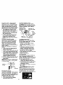
II. SLOPE OPERATION
I. GENERAL OPERATION
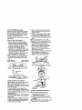
Slopes are a major factorrelated to loss-of• Read, understand, and follow all
control and tipover accidents,which can reinstructions in the manual and on the
sult in severe injury or death. All slopes
machine before starting.
require extra caution. If you cannot back up
• Only allow responsible adults, who are
the slope or if you feel uneasy on it, do not
familiar with the instructions,to operate
mow it.
the machine.
DO:
• Clear the area of objects such as rocks,
• Mow up and down slopes, not across.
toys, wire, etc., which could be picked
• Remove obstacles such as rocks, tree
up and thrown by the blade.
limbs, eta.
• Be sure the area is clear of other people
Watch for holes, ruts, or bumps. Uneven
before mowing. Stop machine if anyone
terrain could ovedum the machine. Tall
enters the area.
grass can hide obstacles.
• Never carry passengers.
• Do nol mow in reverse unless absolutely
Use slow speed. Choose a low gear so
necessary. Always look down and
that you will not have to stop or shift
behind before and while backing.
while on the slope.
Follow the manufacturer'srecommenda• Be aware of the mower discharge
direction and do not point it at anyone.
tions for wheel weights or counterDo not operate the mower without either
weights to improve stability.
Use extra care with grass catchers or
the entire grass catcher or the guard in
place.
other attachments. These can change
• Slow down before turning.
the stability of the machine.
• Never leave a running machine
Keep all movement on the slopes slow
unattended. Always tam off blades, set
and gradual. Do not make sudden
parking brake, stop engine, and remove
changes in speed or direction.
keys before dismounting.
Avoid starting or stopping on a slope, If
tires lose traction, disengage the blades
• Turn off blades when not mowing.
and proceed slowly straight down the
• Stop engine before removing grass
slope.
catcher or unclogging chute.
DO NOT:
• Mow only in daylight or good artificial
light.
• Do not turn on slopes unless necessary,
• Do not operate the machine while under
and then, rum slowlyand gradually
the influence of alcohol or drugs.
downhill, if possible.
• Watch for traffic when operating near or
• Do not mow near drop-offs, ditches,or
crossing roadways.
embankments. The mower could
• Use extra care when loading or unloadsuddenly turn over if a wheel is over the
ing the machine into a trailer or truck.
edge of a cliffor ditch, or if an edge
• Data indicates that operators, age 60
caves in.
years and above, are involved in a large
• Do not mow on wet grass. Reduced
percentage of dding mower-related
tractioncould cause sliding.
injuries. These operators should
• Do not try to stabilize the machineby
evaluate their ability to operate the dding
puttingyour foot on the ground.
mower safely enough to protect them• Do not use grass catcher on steep
selves and others from serious injury.
slopes.
• Keep machine free of grass, leaves or
other debris build-up which can touch
hot exhaust / engine parts and bum. Do
not allow the mower deck to plow leaves
or other dabds which can cause buildup to occur. Clean any oil or fuel
spillage before operating or storing the
machine. Allow machine to cool before
storage.
3
III. CHILDREN
Tragic accidents can occur if the operator
is not alert to the presence of children.
Children are often attracted to the
machine and the mowing activity. Never
assume that children will remain where
you last saw them.
• Keep children out of the mowing area
and under the watchful care of another
responsible adult.
• Be alert and turn machine off if children
enter the area.
• Before and when backing, look behind
and down for small children.
• Never carry children. They may fall off
and be seriously injured or interfere
with safe machine operation.
• Never allow children to operate the
machine.
• Use extra care when approaching blind
corners, shrubs, trees, or other objects
that may obscure vision.
IV. SERVICE
• Use extra care in handling gasoline
and other fuels. They are flammable
and vapors are explosive.
-Use only an approved container.
-Never remove gas cap or add fuel
with the engine running. Allow
engine to cool before refueling. Do
not smoke.
-Never refuel the machine indoors.
- Never store the machine or fuel
container inside where there is an
open flame, such as a water heater.
• Be sure the area is clear of other
people before mowing. Stop machine if
anyone enters the area.
• Never carry passengers or children
even with the blades off.
• Do not mow in reverse unless absolutely necessary. Always look down
and behind before and while backing.
• Never carry children. They may fall off
and be seriously injured or interfere
with safe machine operation.
• Keep children out of the mowing area
and under the watchful care of another
4
responsible adult.
• Never run a machine inside a closed
area.
• Keep nuts and bolts, especially blade
attachment bolts, tight and keep
equipment in good condition.
• Never tamper with safety devices.
Check their proper operation regularly.
• Keep machine free of grass, leaves, or
other debris build-up. Clean oil or fuel
spillage. Allow machine to cool before
storing.
• Stop and inspect the equipment if you
strike an object. Repair, if necessary,
before restarting.
• Never make adjustments or repairs
with the engine running.
• Grass catcher components are subject
to wear, damage, and deterioration,
which could expose moving parts or
allow objects to be thrown. Frequently
check components and replace with
manufacturer's recommended parts,
when necessary.
• Mower blades are sharp and can cut.
Wrap the blade(s) or wear gloves, and
use extra caution when servicing them.
• Check brake operation frequently.
Adjust and service as required.
• Be alert and turn machine off if children
enter the area.
• Before and when backing, look behind
and down for small children.
• Mow up and down slopes (15° Max),
not across.
• Remove obstacles such as rocks, tree
limbs, etc.
• Watch for holes, ruts, or bumps.
Uneven terrain could overturn the
machine. Tall grass can hide obstacles.
•
Use slow speed. Choose a low gear so
that you will not have to stop or shift
while on the slope.
• Avoid starting or stopping on a slope. If
tires lose traction, disengage the
blades and proceed slowly straight
clown the slope.
• If machine stops while going uphill,
disengage blades, shift into reverse
and back down slowly.
• Do not turn on slopes unless necessary, and then, turn slowly and gradually downhill, if possible.
,_Look for this symbol to point out
important safety precautions, it means
CAUTION[t! BECOMEALERT!!! YOUR
SAFETY IS INVOLVED.
_CAUTION:
In order to prevent
accidental starting when setting up,
transporting, adjusting or making repairs,
always disconnect spark plug wire and
place wire where it cannot contact spark
plug.
,_CAUTION:
Do not coast down a hill in
neutral you may lose control of the
tractor.
_CAUTION:
Tow only the attachments
that are recommended by and comply
with specifications of the manufacturer of
your tractor. Use common sense when
towing. Operate only at the lowest
possible speed when on a slope. Too
heavy of a load, while on a slope, is
dangerous. Tires can lose traction with
the ground and cause you to lose control
of your tractor.
_ILWARNING: Engine exhaust some of
its constituents, and certain vehicle
components contain or emit chemicals
known to the State of California to cause
cancer and birth defects or other reproductive harm.
_WARNING:
Battery posts, terminals
and related accessories contain lead and
lead compounds, chemicals known to the
State of California to cause cancer and
birth defects or other reproductive harm.
Wash hands after handling.
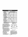
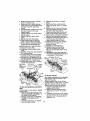
PRODUCT
SPECIFICATIONS
3ASOLINE 3.5GALLONS
CAPACITY
_ND TYPE:
:_lL TYPE
IAPI-SF-SJ):
ILCAPAClTY:
UNLEADED
REGULAR
SAE 30
(ABOVE 32°F)
SAE 5W-30
{BELOW 32°F)
W/FILTER: 4,0PINTS
W/OFILTER:3.75 PINTS
CHAMPION RC12YC
;PARK PLUG:
GAP: .040")
GROUND SPEED FORWARD: 0-5.5
(MPH):
REVERSE: 0-2.4
"IRE PRESSURE: FRONT: 14 PSI
REAR: 10PSI
;HARGING
SYSTEM:
16 AMPS @ 360ORPM
BATTERY:
AMP/HR:
30
MIN. CCA: 240
CASE SIZE: U 1R
BLADE BOLT
TORQUE:
45-55 FT. LBS.
CONGRATULATIONS on your purchase
of a new tractor, It has been designed,
engineered and manufactured to give you
the best possible dependability and
performance.
Should you experience any problem you
cannot easily remedy, please contact a
Sears or other qualified service center.
We have competent, well-frained technicians and the proper tools to service or
repair thistractor.
Please read and retain this manual. The
instructionswill enable you to assemble
and maintain your tractor properly.
Always observe the "SAFETY RULES".
REPAIR AGREEMENT
A Repair Agreement is available on this
product. Contact your nearest Sears
store for details.
CUSTOMER RESPONSIBILITIES
• Read and observe the safety rules.
• Follow a regular schedule in maintaining, caring for and usingyour tractor.
• Follow the instructionsunder "Maintenance" and "Storage" sections of this
owner's manual.
_:_WARNING: This tractor is equipped
with an internal combustionengine and
should not be used on or near any
unimproved forest-covered, brushcovered or grass-covered land unless the
engine's exhaust system is equipped with
a spark attester meeting applicable local
or state laws (if any). If a spark arrester is
used, it should be maintained in effective
working order by the operator.
In the state of Califomia the above is
required by law (Section 4442 of the
California Public Resources Code).
Other states may have similar laws.
Federal laws apply on federal lands. A
spark arrester for the muffler is available
through your nearest Sears service
center (See REPAIR PARTS section of
this manual).
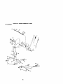
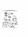
III
ste_..g
Steering
I
Wheel Insert
Wheel
Steering Sleeve
(1)w_
17/32 x 1÷3/16 x 12 Gauge _:_
_(1)
Knob
Mower
Retainer Springs
(2)Flanged
)
(1)Front Plate
_
"
(2) Retainer Springs (single loop)
a
4) Adjusting _Bar
_--_ Gauge(4) Wheels
Retainer Springs
(4) Clevis Pins
;
) Wheels
0_
(
_
(4) Washers _
3/8 x 3/4 x 14 G
_'0_ Nose Roller
f 12)
Ro×.o.o _2
K/1 R.1 R v I
........
Video Cassette
Shoulder Boll
Nose Roller_
J
.
_(4)
Keys
) Washe
17/32x7/Sx16GaV
Slope Sheet
For Future Use
7
Your new tractor has been assembled at the factory with exception of those parts left
unassembled for shipping purposes. To ensure safe and proper operation of your
tractor all parts and hardware you assemble must be tightened securely. Use the
correct tools as necessary to insure proper tightness. Review the video cassette before
you begin.
TOOLS REQUIRED FOR ASSEMBLY
A socket wrench set will make assembly
easier. Standard wrench sizes you need
are listed below.
(1) 9/16" wrench
(1) 3/4" Socket w/
(1) 1/2" wrench
drive ratchet
(1) Utilityknife
(1) Pliers
(1) Tire pressure gouge
When dght or left hand is mentioned in
this manual, it means, from your point of
view, when you are in the operating
position (seated behind the steering
wheel).
TO REMOVE TRACTOR FROM
CARTON
UNPACK CARTON
1. Remove all accessible loose parts
and parts cartons from carton.
2. Cut, from top to bottom, along lines on
all four comers of carton, and lay
panels flat.
3. Remove mower and packing materials.
4. Check for any additional loose parts
or cartons and remove.
BEFORE REMOVING TRACTOR
FROM SKID
ATTACH STEERING WHEEL
1, Remove Iocknut and large flat washer
from steering shaft.
2. Position front wheels of the tractor so
they are pointing straight forward.
3. Slide the steedng sleeve over the
steering shaft.
4. Position steedng wheel so cross bars
are horizontal (left to right) and slide
onto steering wheel adapter.
5, Secure steering wheel to steering
shaft with Iocknut and large flat
washer previously removed. Tighten
securely.
6. Snap steering wheel insert into center
of steedng wheel,
7. Remove protective materials from
tractor hood and griit.
IMPORTANT; Check for and remove any
staples in skid that may puncturetires
where tractor is to roll offskid.
_
I//'_\\I
j__--- Steering
/_
I( )1
w.eel Insert
I_---Lock
Nut
__ge
FlatWasher
Sleering _
Wheel_
SteeringWheel
Adapter_
SteetlRg
Shaft
Steering
_J
)
w
__
"_?_,
i_.j_._.:.,..
Sleeve
',l ":
_ ,_
-
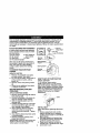
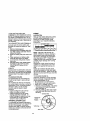
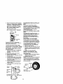
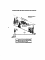
HOW TO SET UP YOUR TRACTOR
CHECK BATTERY
1. Lift hood to raised position.
NOTE: If this battery is put into service
after month and year indicated on label
(label located between terminals) charge
battery for minimum of one hour at 6-10
amps. (See "BATTERY" in Maintenance
section of this manual for charging
instructions).
.=
,..,
,,
INSTALL SEAT
Adjust seat before tighteningadjustment
knob.
1, Remove adjustment knob and flat
washer securing seat to cardboard
packing and set aside for assembly ot
seat to tractor.
2. Pivot seat upward and remove from
the cardboard packing. Remove the
cardboard packing and discard.
3. Place seat on seat pan so head of
shoulder bolt is positioned over large
8
slotted hole in pan,
4. Push
downonseatto engage
5.
6,
7.
8.
9.
shoulder bolt in slot and pull seat
towards rear of tractor.
Pivot seat and pan forward and
assemble adjustment knob and flat
washer loosely. De not tighten,
Lower seat into operating position and
sit in seat.
Slide seat until a comfortable position
is reached which allows you to press
clutch/brake pedal all the way down,
Get eft seat without moving its
adjusted position.
Raise seat and tighten adjustment
knob securely.
Seat
Shoulder
Bolt
1. Be sure all the above assembly steps
have been completed.
2. Check engine off level and fill fuel
tank with gasoline.
3. Place freewheel control in "transmission engaged" position.
4. Sit on seat in operating position,
depress brake pedal and set the
parking brake,
5. Press lift lever plunger and raise
attachment lift lever to its highest
position.
6. Start the engine. After engine has
started, move throttle control to idle
position.
7. Release parking brake.
8. Slowly depress forward drive pedal
and drive tractor off skid.
9. Apply brake to stop tractor and set
parking brake.
1O.Turn ignition key to "OFF" position.
Continue with the instructions that follow.
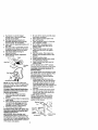
ASSEMBLE GAUGE WHEELS TO
MOWER DECK
Flat Washer
\
NOTE: You may now roll or drive your
tractor off the skid. Fellow the appropriate
instruction below to remove the tractor
from the skid.
TO ROLLTRACTOR
OFF SKID (See
Operation section for location and
function of controls)
1. Press lift lever plunger and raise
attachment lift lever to itshighest
position,
2. Release parking brake by depressing
brake pedal.
3, Place freewheel control in freewheeling position to disengage transmission {See "To TRANSPORT" in the
Operation section of this manual).
4. Roll tractorforward off skid.
TO DRIVE TRACTOR OFF SKID (See
Operation section for location and
function of controls)
WARNING: Beforestarting, read,
understand and follow all instructions in
the Operation section of this manual. Be
sure tractor is in a well-ventilated area. Be
sure the area in front of tractor is clear of
other people and objects.
The gauge wheels are designed to keep
the mower deck in proper position when
operating mower. Be sure they are
properly adjusted to ensure optimum
mower performance.
1. Slide gauge wheel bar down into
bracket channel, Be sure that gauge
wheel bar aligning holes are on top.
Assemble gauge wheels as shown
using shoulder bolts, 3/8 washers and
3/8-16 center Iocknuts and tighten
securely,
2. For ease of mower to tractor assembly, raise gauge wheels to highest
position and retain with clevis pins
and spring retainers,
NOTE: Adjust gauge wheels before
operating mower, See "TO ADJUST
GAUGE WHEELS" in the Operation
section of this manual.
RetainerSpring
//f
Shoulder Adjusting
I
3/8 Washer/
- _
3,8-te
Oooro.
Locknut
TOATTACH
NOSE
ROLLER
1. Positionbrackets, 17/32 x 7/8 x 16
gauge washers, and nose miler
between deck mounting brackets as
shown. Be sure to position brackets
on correct side, as shown.
2. Install hex bolts and lock nuts as
shown. Tighten hardware securely.
NOTE: Be sure bracket tabs are positioned in tab holes in deck brackets.
TabHole
Nose _oller
Lock "B"
Nut
Bracket
Hex_
V
Washer
INSTALL MOWER AND DRIVE BELT
Be suretrac!oris on levelsurfaceand mower
suspension arms are raised with attachment
lift cont_. Engage parkingbrake.
1. Cut and remove ties securing antisway bar and belts. Swing anti-sway
bar to left side of mower deck.
2. Slide mower under tractor with
deflector shield to right side of tractor.
IMPORTANT: Check belt lor proper
routingin all mower pulley grooves.
3. If equipped, tum height adjustment
knob countemlockwise until it steps.
4. Lower mower linkage with attachment
lift control.
5. Be sure belt tension md is in disengaged position.
Lock
Belt TensionRod
DisengagedPosition
Chassis
o
6. Install belt into electdc clutch pulley
groove.
7. Place the suspension arms on
outward pointing deck pins. Retain
with double loop retainer spdng with
loops up as shown.
8. Install front plate assembly to tractor
suspension brackets and retain with
single loop retainer spdngs as shown.
9. Position front plate assembly between
lront mower brackets. Raise deck and
plate assembly to align holes and
insert flanged pins. Secure pins with
double loop retainer springs between
the plate assembly and mower
brackets.
NOTE: To assist in locating hole in
flanged pin, the hole in pin is inline with
notch on head of pin. If necessary, move
side-to-side to give space between plate
and mower brackets.
IMPORTANT: Check belt for proper
routing in all mower pulley grooves.
1O,Engage belt tension rod by pushing
rod into locking bracket.
_CAUTION: Belt tension rod is spring
loaded. Have a tight grip on rod and
engage slowly,
11 ,Connect anti-sway bar to chassis
bracket under left footrest and retain
with double loop retainer spring.
12,If equipped, turn height adiustment
knob clockwise to remove slack from
mower suspension.
13. Raise deck to highest position.
14.Adjust gauge wheels before operating
mower as shown in the Operation
section of this manual.
Electric Clutch
Pulley '
Front
Mower
Bracket
Gauge
Wheel
Front Suspension
Brackets
Front Plate Assembly
p
Retainer Spdngs
Single
Loop
Retainer
Springs
Double Loop
Retainer Spring
Anti-Swey
USEPUERS FOR
RETAINERSPRINGS Suspension Arms
I _L_p
Up
Spring (Outward
Double Loop Retainer
pointing deck pins)
Shield
10
CHECK TIRE PRESSURE
The tires on your tractor were overinflated
at the factory for shipping purposes.
Correct tire pressure is important for best
cutting performance.
• Reduce tire pressure to PSI shown in
"PRODUCT SPECIFICATIONS" section
of this manual.
CHECK DECK LEVELNESS
For best cutting results, mower housing
should be properly leveled. See "TO
LEVEL MOWER HOUSING" in the
Service and Adjustments section of this
manual.
CHECK FOR PROPER POSITION OF
ALL BELTS
See the figures that are shown for
replacing motion and mower blade drive
belts in the Service and Adjustments
section of this manual, Verify that the
belts are routed correctly.
CHECK BRAKE SYSTEM
After you ]eam how to operate your
tractor,check to see that the brake is
propedy adjusted. See "TO ADJUST
BRAKE" in the Service and Adjustments
section of this manual.
_CHECKUST
BEFORE YOU OPERATE AND ENJOY
YOUR N EW TRACTOR, WE WISH TO
ASSURE THATYOU
RECEIVE THE BEST
PERFORMANCE
AND SATISFACTION
FROM THIS QUALITY PRODUCT.
PLEASE REVIEW THE FOLLOWING
CHECKLIST:
,/ All assembly instructions have been
completed.
,/No remaining loose parts in carton.
Battery is properly prepared and
charged. (Minimum I hour at 6 amps).
#"Seat is adjusted comfortably and
tightened securely.
,I All tires are properly inflated. (For
shipping purposes, the tires were
overthflated at the factory).
•," Be sure mower deck is properly leveled
side-to-side/front-to-rear for best cutting
results. (Tires must be propedy inflated
for leveling).
•/" Check mower and drive belts. Be sure
they are routed propedy around pulleys
and inside all belt keepers.
#" Check wiring. See that all connections
are still secure and wires are proper_y
clamped.
v" Before driving tractor, be sure freewheel control is in drive position.
WHILE LEARNING HOWTO USE YOUR
TRACTOR, PAY EXTRAA]-rENTION TO
THE FOLLOWING IMPORTANT ITEMS:
,/ Engine oil is at proper level.
•," Fuel tank is fitied with fresh, clean,
regular unleaded gasoline.
J Become familiar with all controls - their
location and function. Operate them
before you start the engine.
,,/Be sure brake system is in safe
operating condition.
J It is important to purge the transmission
before operating your tractor for the first
time. Follow proper starting and
transmission purging instructions (See
"TO START ENGINE" and "PURGE
TRANSMISSION" in the Operation
section of this manual).
11
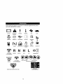
These symbols may appear on your tractor OFin literature supplied with the product.
Learn and understand their meaning.
BATTERY
CAUTION
OR
REVERSE
FORWARD
FAST
SLOW
WARNING
ENGINE ON
ENGINE OFF
FUEL
CHOKE
OIL PRESSURE
MOWER
_r_R
ATrACHMENT
CLUTCH
N
REVERSE
NEUTRAL
HEIGHT
LIGHTS ON
!
OVER TEMP
LIGHT
PARKING BRAKE
LOCKED
H
L
HIGH
LOW
MOWER
UNLOCKED
LIFT
ENGAGED
_(_)
ATTACHMENT
IGNITION
CLUTCH
KEEP AREA CLEAR
{SEE SAFETY
DISENGAGED
SLOPE
RULES
HAZARDS
SECTION)
m=-.
FREE WHEEL
DANGER,
KEEP HANDS
AND FEET
AWAY
(Automatic Models only)
12
KNOWYOUR TRACTOR
READ THIS OWNER'S MANUAL AND SAFETY RULES BEFORE OPERATING
YOUR TRACTOR
Compare the illustrations with your tractor to familiadze yeurseff with the locations of
various controlsand adjustments. Save this manual for future reference.
Hourmeter
Ammeter
Ignition '
Switch
Light Switch Poshtion
Attachment Clutch Switch
Attachment Lift Lever
.Reverse Drive Pedal
Adjustment
Brake
Freewheel
Control Lever
Our tractors conform to the safety standards of the
American National Standards Institute.
ATTACHMENT CLUTCH SWITCH: Used
to engage the mower blades, or other
attachments mounted to your tractor,
LIGHT SWITCH: Turns the headlights on
and off.
THRO'I-FLE CONTROL - Used to control
engine speed.
CHOKE CONTROL - Used when starting
a cold engine.
BRAKE PEDAL: Used for braking the
tractor and startingthe engine.
FREEWHEEL CONTROL: Disengages
transmission for pushing or slowly towing
the tractor with the engine off.
ATTACHMENT LIFT LEVER: Used to
raise, lower and adjust the mower deck
or other attachments mounted to your
tractor,
LIFT LEVER PLUNGER: Used to release
attachment lift lever when changing its
position.
IGNITION SWITCH: Used for startingand
stopping the engine.
AMMETER: Indicates battery charging (+)
or discharging (-).
PARKING BRAKE: Locks clutch/brake
into the brake position.
FORWARD DRIVE PEDAL - Used for
forward movement of tractor.
REVERSE DRIVE PEDAL- Used for
reverse movement of tractor.
CRUISE CONTROL LEVER - Used to set
forward movement of tractor at desired
speed without holding the forward drive
pedal,
HOURMETER - Indicates hours of
operation.
13
Theoperation of any tractor can result
in foreign objects thrown into the
eyes, which can result in severe eye damage. Always wear safety glasses
or eye shields while operating your tractor or performingany adjustments
or repairs. We recommend a wide vision safety mask over spectacles, or
standard safety glasses.
HOW TO USE YOUR TRACTOR
TO SET PARKING BRAKE
Your tractor is equipped with an operator
presence sensing switch. When engine
is running, any attempt by the operator to
leave the seat without first setting the
parking brake will shut off the engine.
1. Depress brake pedal into full "BRAKE"
position and hold.
2. Place parking brake lever in "ENGAGED" position and release
pressure from brake pedal Pedal
should remain in "BRAKE position.
Make sure parking brake will hold
tractor secure.
AttachmentClutch
Push-Into
SwitchPullOutTo
"Disengaged" "Engage"
IMPORTANT: Leaving the ignitionswitch
in any position other than "OFF" will
cause the battery to be discharged,
(dead).
NOTE= Under certain conditionswhen
tractor is standing idle with the engine
running, hot engine exhaust gases may
cause "browning" of grass. To eliminate
this possibility, always stop engine when
stopping tractor on grass areas.
_JI,CAUTION: Always stop tractor
completely, as described above, before
leaving the operator's position; to empty
grass catcher, etc.
THROTTLE CONTROL
Always operate engine at full throttle.
• Operating engine at less than full
throttle reduces the battery charging
rate.
Forward
Choke
DrivePedal
• Full throttleoffers the best bagging and
mower performance.
TO USE CHOKE CONTROL
Thrott_C°ntr°
IgnitionKey
Use choke control whenever you are
starting a cold engine. Do not use to start
a warm engine.
Brake._
_1_
• To engage choke control,pull knob out.
Positio
Reverse
Slowly push knob in to disengage.
Drive TO MOVE FORWARD AND
BACKWARD
The direction and speed of movement is
e
Disengaged
..
I' controlled by the forward and reverse
Position Position
Pos_bon
Lever
drive pedals.
1. Start tractor and release parking
STOPPING
brake.
MOWER BLADES 2. Slowly depress forward or reverse
• To stop mower blades,move attachddve pedal to begin movement.
ment clutch switch to "DISENGAGED"
Ground speed increases the further
position.
down the pedal is depressed.
GROUND DR_VE TO USE CRUISE CONTROL
• To stop ground drive, depress brake
The cruise control feature can be used for
pedal into full =BRAKE" position.
IMPORTANT: Forward and reverse drive
forward travel only.
1. With forward drive pedal depressed to
pedals return to neutral position when not
depressed.
desired speed, move cruise control
ENGINE lever forward to =SET" position and
hold while liftingyour foot off the
• Move throttle control to slow position.
NOTE: Failure to move throttle control to
pedal, then release the cruise control
lever.
slow position and allowing engine to idle
To disengage the cruise control, pull the
before stopping may cause engine to
"backfire".
lever backward to "OFF" position,or fully
depress the brake pedal.
• Turn ignition key to "OFF" position and
remove key Always remove key when
TO ADJUST MOWER CUI-13NG HEIGHT
leaving tractor to prevent unauthorized
The position of the attachment lift lever
use.
determines the cutting height.
• Never use choke to stop engine.
• Grasp lift lever.
• Press plunger with thumb and move
14 lever to desired position.
TO STOP MOWER BLADES disengage attachment clutch control.
_,CAUTION: Do not operate the mower
without either the entire grass catcher, on
mowers so equipped, or the deflector
shield in place.
AttachmentClutch
AttachmentLift
SwitchPull Out To
Lever High PosiUon
=Eng
--Low
Position
The cutting height range is approximately 1-1/2 to 4". The heights are
measured from the ground to the blade
tipwith the engine not running. These
heightsare approximate and may vary
depending upon soil conditions, height of
grass and types of grass being mowed.
The average lawn should be cut to
approximately 2-1/2 inches during the
cool season and to over 3 inches
during hot months. For healthier and
better looking lawns, mow often and
after moderate growth.
• For best cutting performance, grass
over 6 inches in height should be
mowed twice. Make the first cut
relatively high; the second to desired
height.
TO ADJUST GAUGE WHEELS
Gauge wheels are properly adjusted
when they are slightlyoft the ground
when mower is at the desired cutting
height in operating position. Gauge
wheels then keep the deck in proper
position to help prevent scalping in most
terrain conditions.
NOTE: Be sure tractor is on a flat level
surface.
t. Lower mower and adjust mower to
desired cutting height.
2. Remove retainer spring and clevis pin
which secure each gauge wheel bar.
3. Lower gauge wheels to ground. Raise
gauge wheels slightPy to align holes in
bracket and gauge wheel bar and
insert clevis pin. Gauge wheels
shouldbe slightly off the ground.
4. Replace retainer spring into cJevJspin.
5. Be sure all gauge wheels are in the
same setting.
IMPORTANT: Be sure to readjust gauge
wheels if you change the cutting height
of the mower deck.
Deflector
Push ]n To
"Disengage_
TO OPERATE ON HILLS
_,CAUTION: Do not drive up or down
hills with slopes greater than 15° and do
not drive across any slope.
• Choose the slowest speed before
starting up or down hills.
• Avoid stopping or changing speed on
hills.
• If stopping is absolutely necessary,
push brake pedal quickly to brake
.position and engage parking brake.
• To restart movement, slowly release
parking brake and brake pedal.
• Slowly depress appropriate drive pedal
to slowest setting.
• Make all turns slowly.
TO TRANSPORT
When pushing or towing your tractor, be
sure to disengage transmissionby
placing freewheel control in freewheeling
position. Free wheel control is located at
the rear drawbar of tractor.
1. Raise attachment lift to highest
position with attachment lift control.
2. Pull freewheel control out and into the
slot and release so it is held in the
disengaged position.
• Do not push or tow tractor at more than
two (2) MPH.
• To re-engage transmission, reverse
above procedure.
NOTE: To protect hood from damage
when transporting your tractor on a truck
or a trailer, be sure hood is closed and
secured to tractor. Use an appropriate
means of tying hood to tractor (rope, cord,
etc.).
Retainer
Sprin
TO OPERATE MOWER
Your tractor is equipped with an operator
presence sensing switch. Any attempt by
the operator to leave the seat with the
engine running and the attachment clutch
engaged will shut off the engine.
1. Select desired height of cut.
2. Start mower blades by engaging
attachment clutch control.
15
TOWING CARTS AND OTHER ATTACHMENTS
Tow only the attachments that are
recommended by and comply with
specificationsof the manufacturer of your
tractor. Use common sense when towing.
Too heavy of a load, while on a slope, is
dangerous. Tires can lose traction with
the ground and cause you to lose control
of yourtractor.
BEFORE STARTING THE ENGINE
CHECK ENGINE OIL LEVEL
The engine in your tractor has been
shipped, from the factory, already filled
with summer weight oil.
1. Check engine oil with tractor on level
ground.
2. Remove oil fill cap/dipstick and wipe
clean, reinsert the dipstick and screw
cap tight, wait for a few seconds,
remove and read oil level If necessary, add oil until =FULL" mark on
dipstick is reached. Do not overfill.
• For cold weather operation you should
change oil for easier starting (See =OIL
VISCOSITY CHART" in the Maintenance section of this manual).
• To change engine oil, see the Maintenance section in this manual.
ADD GASOLINE
• Fill fuel tank. Use fresh, clean, regular
unleaded gasoline with a minimum of
87 octane. (Use of leaded gasoline will
increase carbon and lead oxide
deposits and reduce valve life), Do not
mix oil with gasoline. Purchase fuel in
quantities that can be used within 30
days to assure fuel freshness.
IMPORTANT: When operating in temperatures below 32°F(0°C), use fresh,
clean winter grade gasoline to help
insure good cold weather starting.
_,WARNING: Experience indicates that
alcohol blended fuels (called gasohol or
using ethanol or methanol) can attract
moisture which leads to separation and
formation of acids during storage. Acidic
gas can damage the fuel system of an
engine while in storage. To avoid engine
problems, the fuel system should be
emptied before storage of 30 days or
longer. Drain the gas tank, start the
engine and let it run until the fuel lines
and carburetor are empty. Use fresh fuel
next season, See Storage Instructions for
additional information. Never use engine
or carburetor cleaner products in the fuel
tank or permanent damage may occur.
_.CAUTION: Fill to bottom of gas tank
filler neck. Do not overfill. Wipe off any
spilled oil or fuel. Do not store, spill or use
gasoline near an open flame.
TO START ENGINE
When starting the engine for the first time
or if the engine has run out of fuel, it will
take extra cranking time to move fuel from
the tank to the engine.
t. Be sure freewheel control is in the
transmission engaged position.
2. Sit on seat in operating position,
depress brake pedal and set parking
brake.
3. Move attachment clutch to "DISENGAGED" position.
4. Move throttle control to fast position
5. Pull choke control out for a cold
engine start attempt. For a warm
engine start attempt the choke control
may not be needed.
NOTE: Before starting, read the warm and
cold starting procedures below.
6. Insert key into ignition and turn key
clockwise to =START" position and
release key as soon as engine starts.
Do not run starter continuously for
more than fifteen seconds per minute.
If the engine does not start after
several attempts, push choke control
in, wait a few minutes and try again. If
engine still does not start, pull the
choke control out and retry.
WARM WEATHER STARTING (50° F and
above)
7. When engine starts, slowly push
choke control in until the engine
begins to run smoothly. If the engine
starts to run roughly, pull the choke
control out slightly for a few seconds
and then continue to push the control
in slowly.
• The attachments and ground drive can
now be used. If the engine does not
accept the load. restart the engine and
allow it to warm up for one minute
using the choke as described above.
COLDWEATHER STARTING (50 F and
below)
7. When engine starts, slowly push
choke control in until the engine
begins to run smoothly. Continue to
push the choke control in small steps
allowing the engine to accept small
changes in speed and load, until the
choke control is fully in. If the engine
starts to run roughly, pull the choke
control out slightly for a few seconds
and then continue to push the control
in slowly. This may require an engine
warm-up pedod from several seconds
to several minutes, depending on the
16
temperature.
AUTO MATIC TRANS MISSION WARM UP
Before driving the unit in cold weather,
the transmission should be warmed up as
follows:
1. Be sure the tractor is on level ground.
2. Release the parking brake and let the
brake slowly return to operating
position.
3. Allow one minute for transmissionto
warm up. This can be done dudng the
engine warm up pedod.
• The attachments can be used dudng
the engine warm-up period after the
transmission has been warmed up and
may require the choke control be
pulled out slightly.
NOTE: If at a high altitude (above 3000
feet) or in cold temperatures (below 32 F)
the carburetor fuel mixture may need to
be adjusted for best engine performance.
See =TOADJUST CARBURETOR" in the
Service and Adjustments section of this
manual.
PURGE TRANSMISSION
ACAUTION:
Never engage or disengage
freewheel lever while the engine is
running.
To ensure proper operation and performance, it is recommended that the
transmission be purged before operating
tractor for the first time. This procedure will
remove any trapped air inside the transmission which may have developed during
shipping of your tractor.
IMPORTANT: Should your transmission
require removal for service or replacement,
it should be purged after reinstallaUon
before operating the tractor.
t. Place tractor safely on level surface
with engine off and parking brake set.
2. Disengage transmission by placing
freewheel control in freewheeling
position (See "TO TRANSPORT" in
this section of manual).
3. Sitting in the tractor seat, start engine.
After the engine is running, move
throttle control to slow position.
Disengage parking brake.
4. Depress forward drive pedal to full
forward position and hold for five (5)
seconds and release pedal. Depress
reverse drive pedal to full reverse
position and hold for five (5) seconds
and release pedal. Repeat this
procedure three (3) times.
NOTE: During this procedure there will be
no movement of drive wheels. The air is
being removed from hydraulic drive
system.
5. Shut- oft engine and set parking
brake.
6. Engage transmission by placing
freewheel control in ddving position
(See "TO TRANSPORT" in this section
of manual).
7. Sifting in the tractor seat, start engine.
After the engine is running, move
throttle control to half (1/2) speed.
Disengage parking brake.
8. Drive tractor forward for approximately
five feet then backwards for five feet.
Repeat this ddving procedure three
times.
Your tractor is now purged and now ready
for normal operation.
MOWING TIPS
• Mower should be properly leveled for
best mowing performance. See "TO
LEVEL MOWER HOUSING" in the
Service and Adjustments section of this
manual.
• The left hand side of mower should be
used for trimming.
• Drive so that clippings are discharged
onto the area that has been cut. Have
the cut area to the right of the tractor.
This will result in a more even distribution of clippings and more uniform
cutting.
• When mowing large areas, start by
turning to the right so that clippings will
discharge away from shrubs, fences,
driveways, etc. After one or two
rounds, mow in the opposite direction
making left hand turns until finished.
• If grass is extremely tall, it should be
mowed twice to reduce load and
possible fire hazard from dried clippings. Make first cut relatively high; the
second to the desired height.
• Do not mow grass when it is wet. Wet
grass will plug mower and leave
undesirable clumps. Allow grass to dry
before mowing.
• Always operate engine at full throttle
when mowing to assure better mowing
performance and proper discharge of
matedal. Regulate ground speed by
selecting a low enough gear to give the
mower cutting performance as well as
the quality of cut desired.
• When operating attachments, select a
ground speed that will suit the terrain
and give best performance of the
attachment being used.
17
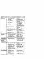
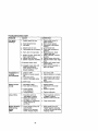
REGULARS ERVICE
c_
_'___Jf
Brake
_o_raUc_
Checkl_re Pressure
T
Check Ope_atc_ PreSence and
Intedoc_ Systems
SERVIC_
J
V'
t/
!/
R
Check fo¢ Loose Fa,steners
A!
SharpeNReplace Mower Blades
Lub_caUon Chad
_4
1_
T!
CheCk BattePj Level
I_B
R
Clean ealtoty and Tenminals
_
Che_k TranSaxle Cootlng
I_
I_
1_'7
b/
V#
Adjust Blade Belt(s) Te_l$ion
KS
A(_F!.stMotion DPive Belt(s) Teo.slo_
_s
Clean Air Filter
Change Engine Oil
Clean Air Screen
_=
_._
_2
V#
G
Inspect Muffler/Spark Atrestet
Replace Oil Filter (If equipPe_
_t,_
N
Ck_an Engin_ Cooling F'I_S
_
Replace Spa_d_Plug
_
Replace Air Filter Paper Cartridge
V*2 I
!V _
Replace Fu_l Filter
1 - C h,_
ff_
oft_t wh_
oporallng u_de_ a h_mw k_
DATES
I
o__ Itlgi_am_ent k_tt _ralur_
3 - If e,q_pped _ilh _1 _ le_. chamge oil v,vlw 50 hour=,
4 - Replace blade= er,o_ open whe_ rnowmg In _
_d.
5. I_e_u_pp_d _h
a0_b_
_/s_.
7. T_gh_a_fro_ _,_kl F_Ol bc]l to 3_ IL I_
Do not _W_r_n_
na_xirnum
LUBRICATION CHART
GENERAL RECOMMENDATIONS
The warrantyon this tractordoes not cover
items that have been subjectedto operator
abuse or negligence. To receive full value
from the warranty,operator must maintain
tractoras instructedin this manual
Some adjustments will need to be made
periodicallyto properly maintain your
tractor.
All adjustments in the Service and
Adjustmentssection of this manual should
be checked at least once each season.
• Once a year you shouldreplace the
spark plug, clean or replace air filter, and
check blades and belts for wear. A new
spark plug and clean air tilterassure
proper air-fuel mixture and help your
engine run better and last longer.
BEFORE EACH USE
1. Check engine oil level.
2, Check brake operation.
3. Check tire pressure.
4. Check operator presence and
interlocksystems for proper operation,
5. Check for loose fasteners.
(_ Spindle
Zerk
Zerk
Front
Wheel
Bearing
Zerk
Wheel
Bearing
Zerk
Zerks
i
GeneralPurposeGrease
_) Refer to Maintenance=ENGINE"Section
IMPORTANT: Do not oil or grease the
pivot points which have special nylon
bear-ings. Viscous lubricantswill attract
dust and dirt that will shortenthe life of
the self-lubricatingbearings. If you feel
they must be lubdcated, use only a dry,
powdered graphite type lubricant
sparingly.
18
TRACTOR
Always observe safety rules when
performing any maintenance.
BRAKE OPERATION
If tractor requires more than six (6) feet
stopping distance at high speed in
highestgear, then brake must be adjusted. (See "TO ADJUST BRAKE in the
" Service and Adjustments section of this
manual).
TIRES
• Maintain proper air pressure in all tires
(See =PRODUCT SPECIFICATIONS"
section of this manual).
• Keep tires free of gasoline, oil, or insect
control chemicals which can harm
rubber.
• Avoid stumps, stones, deep ruts, sharp
objects and other hazards that may
cause tire damage.
NOTE: To seal tire punctures and prevent
flat tires due to slow leaks, tire sealant
may be purchased from your local parts
dealer. "13resealant also prevents tire dry
rot and corrosion.
OPERATOR PRESENCE SYSTEM
Be sure that operator presence and
interlock systems are working properly.If
your tractordoes not functionas described below, repair the problem
immediately.
• The engine should not start unless the
brake pedal is fully depressed and
attachment clutch control is in the
disengaged position.
• When the engine is running, any
attempt by the operator to leave the
seat without first settingthe parking
brake should shut offthe engine.
• When the engine is running and the
attachment clutch is engaged, any
attempt by the operator to leave the
seat should shut offthe engine,
• The attachment clutch should never
operate unless the operator is in the
seat.
BLADE CARE
For best resultsmower blades must be
kept sharp. Replace bent or damaged
blades.
BLADE REMOVAL
1. Raise mower to highest position to
allow access to blades.
NOTE: Protect your hands with gloves
and/or wrap blade with heavy cloth.
2. Remove blade bolt by turning counterclockwise.
3. Install new or resharpened blade with
stamped "THIS SIDE UP" facing deck
and mandrel assembly.
IMPORTANT: To ensure proper assembly,
center hole in blade must align with star
on mandrel assembly.
4. Install and tighten blade bolt securely
(45-55 Ft. Lbs. torque).
IMPORTANT: Special blade bolt is heat
treated.
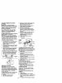
TO SHARPEN BLADE
NOTE: We do not recommend sharpening blade - but if you do, be sure the
blade is balanced.
Care should be taken to keep the blade
balanced. An unbalanced btade will
cause excessive vibration and eventual
damage to mower and engine.
• The blade can be sharpened with a file
or on a grinding wheel. Do not attempt
to sharpen while on the mower.
• To check blade balance, you wiEIneed
a 5/8" diameter steel bolt, pin, or a cone
balancer. (When using a cone balancer, follow the instructions supplied
with balancer.)
NOTE: Do not use a nail for balancing
blade. The lobes of the center hole may
appear to be centered, but are not.
• Slide blade on to an unthreaded
portion of the steel bolt or pin and hold
the bolt or pin parallel with the ground.
if blade is balanced, it should remain in
a horizontal position. If either end of
the blade moves downward, sharpen
the heavy end until the blade is
balanced.
Center Hole
5/8" Bolt
Blade
BATTERY
Your tractor has a battery charging system
which is sufficient for normal use. However, periodic charging of the battery with
an automotive charger will extend its life.
• Keep battery and terminals clean.
19 ° Keep battery bolts tight.
• Keep small vent holes open.
• Recharge at 6-10 amperes for 1 hour.
NOTE: The original equipment battery on
your tractor is maintenance free. Do not
attempt to open or remove caps or covers.
Adding or checking level of electrolyte is
not necessary.
TO CLEAN BATFERY AND TERMINALS
Corrosion and dirt on the battery and
terminals can cause the battery to "leak"
power.
1. Remove terminal guard.
2. Disconnect BLACK battery cable first
then RED battery cable and remove
battery from tractor.
3. Rinse the battery with plain water and
dry.
4. Clean terminals and battery cable
ends with wire brush until bright.
5. Coat terminals with grease or petroleum jelly.
6. Reinstall battery (See "REPLACING
BAI-£ERY" in the SERVICE AND
ADJUSTMENTS section of this
manual).
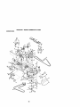
V-BELTS
Check V-belts for deterioration and wear
after 100 hours of operation and replace
if necessary. The belts are not adjustable.
Replace belts if they begin to slip from
wear.
TRANSAXLE COOLING
The transmission fan and cooling fins
should be kept clean to assure proper
cooling.
Do not attempt to clean fan or transmission while engine is running or while the
transmission is hot. To prevent possible
damage to seals, do not use high
pressure water or steam to clean
transaxle.
Inspect cooling fan to be sure fan
blades are intact and clean.
• Inspect cooling fins for dirt, grass
clippings and other materials. To
prevent damage to seals, do not use
compressed air or high pressure
sprayer to clean coolingfins.
TRANSAXLE PUMP FLUID
The transaxle was sealed at the factory
and fluid maintenance is not required for
the life of the transaxle. Should the
transaxle ever leak or require servicing,
contact your nearest authorized service
center/department.
ENGINE
LUBRICATION
Only use high quality detergent oil rated
with API service classificationSF-SJ.
SeEectthe oil's SAE viscositygrade
according to your expected operating
temperature.
NOTE: Although multi-viscosity oils
(5W30, lOW30 etc.) improve starting in
cold weather, these multi-viscosity oils
will result in increased oil consumption
when used above 32'_R Check your
engine oil level more frequently to avoid
possible engine damage from running
low on oil.
Change the oil after every 50 hours of
operation or at least once a year if the
tractor is not used for 50 hours in one
year.
Check the crankcase oil level before
starting the engine and after each eight
(8) hours of operation. 33ghtan oil fill cap/
dipstick securely each time you check the
oil level.
TO CHANGE ENGINE OiL
Determine temperature range expected
before oil change. All oil must meet API
service classification SF-SJ.
• Be sure tractor is on level surface.
• Oil will drain more freely when warm.
• Catch oil in a suitable container.
1. Remove oil flU cap/dipstick. Be careful
not to allow dirt to enter the engine
when changing oil.
2. Remove yellow cap from end of drain
valve and install the drain tube onto
the fitting.
Oil Drain Valve
PosilJon
Closedand
Locked
Yellow
Cap_
D
2O
j"
1
. __
3. Unlock
drainvalvebypushing
inward
slightly
endturning
counterclockwise.
4. Toopen,
pulloutonthedrainvalve.
5. Afteroilhasdrained
completely,
close
andlockthedrainvalveby
pushing
inward
andturning
clockwiseuntilthepinisinthelocked
position
asshown.
6. Remove
thedraintubeandreplace
thecapontototheendofthedrain
valve.
7. Refillengine
withoilthrough
oilfill
dipstick
tube.Pourslowly. Do not
overfill. For approximate capacity
see "PRODUCT SPECIFICATIONS"
section of this manual.
8. Use gauge on oil fill cap/dipstick for
checking level. Be sure dipstick cap
is tightened securely for accurate
reading. Keep oil at "FULL" line on
dipstick.
CLEAN AIR SCREEN
Air screen must be kept free of dirt and
chaff to prevent engine damage from
overheating. Clean with a wire brush or
compressed air to remove dirt and
stubborn dried gum fibers.
CLEAN AIR INTAKE/COOLING AREAS
To insure proper cooling, make sure the
grass screen, cooling fins, and other
external surfaces of the engine are kept
clean at all times.
Every t0O hours of operation (more often
under extremely dusty, dirty conditions),
remove the blower housing and other
cooling shrouds. Clean the cooling tins
and external surfaces as necessary. Make
sure the cooling shrouds are reinstalled.
NOTE: Operating the engine with a
blocked grass screen, dirty or plugged
cooling fins, and/or cooling shrouds
removed will cause engine damage due
to overheating.
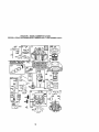
AIR FILTER
Your engine will not run properly using a
dirty air filter. Clean the foam pre-cleaner
after every 25 hours of operation or every
season. Service paper cartridge every
100 hours of operation or every season,
whichever occurs first.
Service air cleaner more often under
dusty conditions.
1. Remove knobs and cover.
TO SERVICE PRE-CLEANER
2. Wash it in liquid detergent and water.
3. Squeeze it dry in a clean cloth.
4. Saturate it in engine oil. Wrap it in
clean, absorbent cloth and squeeze to
remove excess oil.
NOTE: If very dirty or damaged, replace
pre-cleaner.
TO SERVICE CARTRIDGE
5. Clean cartridge by tapping gently on
flat surface. If very dirty or damaged,
replace cartridge.
6. Reinstall precleaner cartridge, cover
and secure with knobs.
IMPORTANT: Petroleum solvents, such
as kerosene, are not to be used to clean
the cartridge. They may cause deterioration of the cartridge. Do not oil cartridge.
Do not use pressurized air to clean or dry
cartridge.
Foam
Pre-Cleaner/
.__Cartridge
ENGINE OIL FILTER
Replace the engine oil filter every season
or every other oil change if the tractor is
used more than 100 hours in one year.
21
MUFFLER
Inspect and replace corroded muffler and
spark arrester (if equipped) as it could
create a fire hazard and/or damage.
SPARK PLUGS
Replace spark plugs at the beginning of
each mowing season or after every 100
hours of operation, whichever occum first.
Spark plug type and gap setting are
shown in "PRODUCT SPECIFICATIONS"
section of this manual
IN-LINE FUEL FILTER
The fuel filter should be replaced once
each season. If fuel filter becomes
clogged, obstructing fuel flow to carburetor, replacement is required.
1. With engine cool, remove filter and
plug fuel line sections.
2. Place new fuel filter in position in fuel
line with arrow pointing towards
carburetor.
3. _e sure there are no fuel line leaks
and clamps are properly positioned,
4. Immediately wipe up any spilled
gasoline.
Clamp
Clamp
CLEANING
• Clean engine, battery, seat, finish, etc.
of all foreign matter.
• Keep finished surfaces and wheels free
of all gasoline, oil, etc.
• Protect painted surfaces with automotive type wax.
We do not recommend using a garden
hose to clean your tractor unless the
alectrical system, muffler, air filter and
carburetor are covered to keep water out,
Water in engine can result in a shortened
engine life.
FuelFilt_
22
CAUTION:
BEFORE
PERFORMING
ANYSERVICE
ORADJUSTMENTS:
1.Depress
brake
pedalfullyand set parking brake.
2.
3.
4.
5.
Place attachment clutch in "DISENGAGED" position.
Turn ignitionkey "OFF" and remove key.
Make sure the blades and all moving parts have completely stopped.
Disconnect spark plug wire from spark plug and place wire where it cannot
come in contact with plug.
TRACTOR
7. Remove retainer springs from
TO REMOVE MOWER
suspension arms at deck and disen1. Place attachment clutch in "DISENgage arms from deck.
GAGED" position.
8. Raise attachment lift to its highest
2. If equipped, turn height adjustment
position.
9. Slide mower forward and remove belt
knob to lowest setting.
3. Lower mower to its lowest position.
from electric clutch pulley.
4. Disengage belt tension rod from lock
10.Slide mower out from under nghtside
bracket.
of tractor.
TO INSTALL MOWER
ACAUTION: Rod is spdng loaded. Have
a tight grip on rod and release slowly.
Follow procedure described in "INSTALL
5. Remove retainer spring holding antiMOWER AND DRIVE BELT" in the
swaybar to chassis bracket and
Assembly section of this manual.
disengage anti-swaybar from bracket.
6. Remove four retainer springs from
front plate assembly and remove
plate.
Electric
Suspension
Clutch PuUey
BeltTension
At{
Rod
,
,)
Front Mower
(Disengaged_,_;,
Bracket
Position)
",
Front
Plate
Chassis
Retainer Springs
(Both Sides)
Retainer
Sprin_
Bracket
Anti-Sway
Bar
Re_iner Spnngs
23
TOLEVEL
MOWER
HOUSING
Adjust the mower while tractor is parked
on level ground or driveway. Make sure
tires are propedy inflated (See "PRODUCT SPECIFICATIONS" section of this
manual). If fires ara over or
undednflated, you will not pmpedy adjust
your mower.
SIDE-TO-SIDE ADJUSTMENT
• Raise mower to its highest position.
• Measure height from bottom edge of
mower to ground level at front comers
of mower. Distance "A" on both sides
of mower should be the same.
• If adjustment is necessary, make
adjustment on one side of mower only.
• To raise one side of mower, tighten lift
link adjustment nut on that side.
• To lower one side of mower, loosen lift
link adjustment nut on that side.
NOTE: Each full turn of adjustment nut
will change mower height about 3/16".
• Recheck measurements after adjusting.
BottomEdgeof
BottomEdge of
Mowerto Ground
Mowerto Ground
\
__Suspension
/
• Before making any necessary adjustments, check that both front linksare
equal in length.
• If links are not equal in length, adjust
one link to same length as other link.
• To lower front of blade, loosen nut "C"
on both front links an equal number of
turns.
NOTE: Each full turn of nut"C" will
change dim. "B"by approximately3/16".
• When distance "B"is 1/8" to 1/2" lower
at front than rear, tighten nut "D"
against trunnion on both front links.
• To raise front of blade, loosen nut "D"
from trunnion on both front links.
Tighten nut "C" on both front linksan
equal number of turns.
• When distance "B" is 1/8" to 1/2" lower
at front than rear, tighten nut "D"
against trunnion on both front links.
• Recheck side-to-side adjustment.
=_ B;ade
=
o
=
BOTH FRONT LINKS MUST BE EQUAL
IN LENGTH
Lift Link
AduJtUstment
FRONT-TO-BACK ADJUSTMENT
IMPORTANT: Deck must be level side-toside. If the following front-to-back
adjustment is necessary, be sure to adjust
both front links equally so mower will stay
level side-to-side.
To obtain the best cutting results, the
mower blades should be adjusted so the
front tip is approximately 1/8" to 1/2" lower
than the rear tip when the mower is in its
highest position.
CAUTION; Blades are sharp. Protect your
hands with gloves an0Vorwrap blade with
heavy cloth.
Check adjustmenton dghtsideoftractor.
Position
any bladeso thetipispointing
straightforward. Measure distance "B"at
front and rear tip of blade.
24
Nut "D_
FrontPlate
ut "C"
Trunnion
Assembly
TO REPLACE
MOWER
DRIVE
BELT
MOWER DRIVE BELT REMOVAL
1. Park tractoron a level surface.
Engage parking brake.
2. Lower mower to its lowest position.
3. Disengage belt tension rod from lock
bracket.
_,CAUTION: Rod is spring loaded. Have
a firm grip on rod an retease slowly.
4, Remove screws from R.H. mandrel
cover and remove cover.
5. Remove any dirt or grass clippings
which may have accumulated around
mandrels and entire upper deck
surface.
6. Disconnect R.H. suspension arm from
rear deck bracket by removing
retainer spring.
7. Carefully roll belt over the top of R.H.
mandrel pulley.
8. Remove belt from electric clutch
pulley.
9. Remove belt from idler pulleys.
1O.Check primary idler arm and two
idlers to see that they rotate freely.
1t.Be sure spring is securely hooked to
primary idler arm and spring arm.
MOWER DRIVE BELT INSTALLATION
12.Install belt in both idlers.
13.1nstall new belt onto electric clutch
pulley.
t4.Carefully roll belt into upper groove of
R.H. mandrel pulley,
iS.Carefully check belt routing making
sure belt is in the grooves correctly.
16.Reconnect R.H. suspensionarm to
rear deck bracket with retainer spnng.
t7.Reassemble R.H. mandrel Cover.
18.Engage belt tension rod by pushing
rod into locking bracket.
Belt Tension
R.H. Mandrel
Electric
Rod
(Disengaged Cover_
Clutch
ulley
Posit.n)
Mandrel
Suspension
Arm
Primary
Idler Arm
4. Carefully roll belt off L.H. mandrel
pulley.
5. Remove belt from center mandrel
pulley, idler pulley, and R.H. mandrel
pulley.
6. Remove any dirt or grass which may
have accumulated around mandrels
and entire upper deck surface.
7. Check secondary idler arm and idler
pulley to see that they rotatefreely.
8. Be sure spring is hooked in secondary
idler arm and secondary spring arm.
9. Install new belt in lower groove of R.H.
mandrel pulley, idler pulley, and
center mandrel pulley as shown.
10.Carefully roll belt over L.H. mandrel
pulley. Make sure belt is in all
grooves properly.
11.Reinstall L.H. mandrel cover.
12. Reinstall mower to tractor {See
"INSTALL MOWER AND DRIVE
BELT" in the Assembly section of this
manual).
13. Reassemble mower drive belt (See
"TO REPLACE MOWER DRIVE BELT"
in this section of this manual).
L.H.
SecondaryIdler Arm
Mandrel
:llerPulle _pdng
jSecondary
pring Arm
Mandrel
TO ADJUST BRAKE
Your tractor is equipped with an adjustable
brake system which is mounted on the
side of the transaxle.
If tractorrequiresmore than six (6) feet
stoppingdistance at high speed in highest
gear on a level dry concrete or paved
surface, then brake must be adjusted.
1. Depress clutch/brake pedal and
engage parking brake.
2. Measure distance between brake
operating arm and nut "A" on brake
rod.
3. If distance is other than 1-3/4", loosen
jam nut and turn nut "A" until distance
becomes 1-3/4". Retighten jam nut
against nut "A".
TO REPLACE MOWER BLADE DRIVE
BELT
Park the tractoron level sudace. Engage
parking brake.
t. Remove mower drive belt (See "TO
REPLACE MOWER DRIVE BELT' in
this section of this manual).
2. Remove mower (See "TO REMOVE
MOWER" in thissection of this
manual).
3. Remove screws from L.H. mandrel
25
cover and remove cover.
4. Road test tractor for proper stopping
distance as stated above. Readjust if
necessary. If stopping distance is still
greater than six (6) feet in highest
gear, further maintenance is necessary. Contact a Sears or other
qualified service center.
WITH PARKING BRAKE "ENGAGED"
Nut
Nut
Operating
Do not touch this nut. If further brake
adjustment is necessary contact a Sears or
other qualified service center.
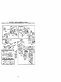
TO REPLACE MOTION DRIVE BELT
Park the tractor on level surface. Engage
parking brake. For assistance, there is a
belt installation guide decal on bottom
side of left footrest.
1. Remove mower (See "TO REMOVE
MOWER" in this section of this
manual.)
2, Disconnect clutch wire harness.
3. Remove clutch locator.
4. Remove belt from stationary idler and
clutching idler.
5. Pull belt slack toward rear of tractor.
Carefully remove belt upwards from
transmission input pulley and over
cooling fan blades.
6. Pull belt toward front of tractorand
remove downwards from around
electric clutch.
7. Install new belt by reversing above
procedure.
Electric_
Clutch
o
TRANSMISSION REMOVAL/REPLACEMENT
Should your transmission require
removal for service or replacement, it
should be purged after reinstallationand
before operatingthe tractor. See =PURGE
TRANSMISSION" in the Operation
section of this manual,
TO ADJUST STEERING WHEEL ALIGNMENT
If steering wheel crossbarsare not
horizontal (left to right) when wheels are
positioned straight forward, remove
steering wheel and reassemble per
instructions in the Assembly section of
this manual.
FRONT WHEEL TOE-IN/CAMBER
The frontwheel toe-in and camber are
not adjustable on your tractor. If damage
has occurredto affect the front wheel toein or camber, contactyour nearest Sears
or other qualified service center.
TO REMOVE WHEEL FOR REPAIRS
1. Block up axle securely.
2. Remove axle cover, retaining ring and
washers to allow wheel removal (rear
wheel contains a square key - Do not
lose).
3. Repair tire and reassemble.
NOTE; On rear wheels only: align
grooves in rear wheel hub and axle.
Insert square key.
4. Replace washers and snap retaining
ring securely in axle groove.
5. Replace axle cover.
NOTE: To seal tire puncturesand prevent
flat tires due to slow leaks, tire sealant
may be purchased from your local parts
dealer. Tire sealant also prevents tire dry
rot and corrosion.
AxleRing
Clutch
Locater
cove,-.
D
SquareKey
./,_
(Rear Wheel Only)
26
'
TOSTART
ENGINE
WITH
AWEAK
BATTERY
_,CAUTION: Lead-acid batteries
generate explosivegases. Keep sparks,
flame and smoking materials away from
batteries. Always wear eye protection
when around batteries,
If your battery is too weak to stad the
engine, it should be recharged. (See
"BATTERY" in the MAINTENANCE
section of this manual).
tf "jumper cables"are used for emergency
starting,follow this procedure:
IMPORTANT: Yourtractor is equipped
with a 12 volt negative grounded system.
The other vehical must also be a 12 volt
negative grounded system. Do not use
your tractorbattery to start other vehicles.
TO A'n'ACHJUMPER CABLES 1. Connect each end of the RED cable to
the POSITIVE (+) terminal of each
battery, taking care not to short
against chassis.
2. Connect one end of the BLACK cable
to the NEGATIVE (-) terminal of fully
charged battery.
3, Connect the other end of the BLACK
cable to good CHASSIS GROUND,
away from fuel tank and battery.
TO REMOVE CABLES, REVERSEORDER 1. BLACK cable first from chassis and
then from the fully charged battery,
2, RED cable last from both batteries.
3. Disconnect BLACK battery cable then
RED battery cable and carefully
remove battery from tractor.
4. Install new battery with terminals in
same position as old battery.
5. Reinstall terminal guard.
6. First connect RED battery cable to
positive (÷) battery terminal with hcx
bolt and keps nut as shown. Tighten
securely.
7. Connect BLACK grounding cable to
negative (-) battery terminal with
remaining hex bolt and keps nut.
Tighten securely
8. Close terminal access doors,
9. Close hood.
keps Nut
TerminaJ
Negative
TO REPLACE HEADLIGHT LAMP
_,CAUTION: When lit, the halogen lamps
get extremely hot. Hold lamp assembly by
the holder and do not touch the bulb,
1. Raise hood.
2. Disconnect harness from lamp
assembly,
3. Rotate counterclockwise and pull
lamp assembly out of the hole in the
backside of the grill
"Positive"(+)_
"Negative"(.) 4, Insed new lamp assembly and rotate
clockwise to lock.
5. Reconnect harness to lamp assembly.
6. Close hood.
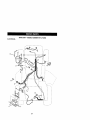
INTERLOCKS AND RELAYS
Loose or damaged wiringmay cause your
tractorto run poorly, stop running,or
prevent itfrom starting.
• Check wiring. See electrical wiring
REPLACING BATTERY
diagram in the Repair Parts section.
TO REPLACE FUSE
_CAUTION:
Do not short battery
terminals by allowing a wrench or any
Replace with 20 amp automotive-type
other object to contact both terminals at
plug-in fuse. The fuse holder is located
behind the dash.
the same time. Before connecting battery,
remove metal bracelets, wristwatch
TO REMOVE HOOD AND GRILL ASbands, nngs, etc.
SEMBLY
Positiveterminal must be connected first
1. Raise hood.
to prevent sparking from accidental
2. Unsnap headlight wire connector.
grounding.
3. Standinfmntoftractor.
Grasp hood at
1. Lift hood to raised position.
sides, tifftoward engine and lift off of
2, Remove terminal guard.
tractor.
4. To replace, reverse above procedure.
27
etor
ENGINE
Maintenance,repair, or reptacernant of the
emissioncontroldevicesand systems,which
are beingdone at the customersexpense,
may be performedby any non-roadengine
repairestablishmentor individual.Warranty
repairs mustbe performedby an authorized
engine manufacture#s serviceoutlet.
TO ADJUST TH RO'l-i"LE CONTROL
CABLE
The throttlecontrol has been preset at the
factory and adjustment should not be
necessary. Check adjustment as described below before loosening cable. If
adjustment is necessary, proceed as
follows:
1. With engine not running, move throttle
control lever to fast position.
2. Check that swivel is against stop. If it is
not, loosen cable clamp screw and
pull cable back until swivel is against
stop. Tighten cable clamp screw
securely.
TO ADJUST CHOKE CONTROL
The choke control has been preset at the
factory and adjustment should not be
necessary. Check adjustment as descdbed below before loosening cable. If
adjustment is necessary, proceed as
follows:
1. With engine not running, move choke
control (located on dash panel) to full
choke position.
2. Loosen knob and remove cover
assembly from air cleaner.
3. Choke should be closed. If it is not,
loosen casing clamp screw and move
choke cable until choke is completely
closed. Tighten casing clamp screw
securely.
4. Replace air cleaner cover assembly
and tighten knob.
TO ADJUST CARBURETOR
Yourcarburetor is not adjustable. If your
engine does not operate properly due to
suspected carburetor problems, take your
tractor to an authorized service center for
repair and/or adjustment.
High speed stop is factory adjusted. Do
not adjust - damage may result.
IMPORTANT: Never tamper with the
engine governor, which is factory set for
proper engine speed. Overspeeding the
engine above the factory high speed
setting can be dangerous. If you think the
engine-governed high speed needs
adjusting, contacta Sears or otherqualified
servicecenter,,which has proper equipment and experience to make any
necessary adjustments.
Screw
28
immediately prepare your tractor for
storage at the end of the season or if the
tractor will not be used for 30 days or
more.
_CAUTION:
Never store the tractor with
gasoline in the tank inside a building
where fumes may reach an open flame or
spark. Allow the engine to cool before
storing in any enclosure.
TRACTOR
Remove mower from tractor for winter
storage. When mower is to be stored for
a periodof time, clean it thoroughly,
remove all dirt, grease, leaves, etc. Store
in a clean, dry area.
1. Clean entire tractor (See =CLEANING"
in the Maintenance section of this
manual).
2. Inspect and replace belts, if necessary
(See belt replacement instructions in
the Service and Adjustments section
of this manual).
3. Lubricate as shown in the Maintenance section of this manual.
4. Be sure that all nuts, bolts and screws
are securely fastened. Inspect moving
parts for damage, breakage and wear.
Replace if necessary.
5. Touch up all rusted or chipped paint
surfaces; sand lightly before painting.
BA'FrER¥
• Fully charge the battery for storage.
• After a period of time in storage, battery
may require recharging.
• To help prevent corrosion and power
leakage during long periods of storage,
battery cables should be disconnected
and battery cleaned thoroughly (see
"TO CLEAN BATFERY AND TERMINALS" in the Maintenance section of
this manual).
• After cleaning, leave cables disconnected and place cables where they
cannot come in contactwith battery
terminals.
• If battery is removed from tractorfor
storage, do not store battery directlyon
concrete or damp surfaces.
ENGINE
FUEL SYSTEM
IMPORTANT: It is important to prevent
gum deposites from forming in essential
fuel system parts such as carburetor,fuel
hose, or tank during storage. Also,
expedance indicates that alcohol
blended fuels (called gasohol or using
ethanol or methanol) can attract moisture
which leads to separation and formation
of acids during storage. Acidic gas can
damage the fuel system of and engine
while in storage.
1. Drain the fuel tank.
2. Start the engine and let it run until the
fuel lines and carburetor are empty.
• Never use engine or carburetor cleaner
products in the fuel tank or permanent
damage may occur.
• Use fresh fuel next season.
NOTE: Fuel stabilizer is an acceptable
alternative in minimizing the formation of
fuel gum deposits dudng storage. Add
stabilizer to gasoline in fuel tank or
storage container. Always follow the mix
ratio found on stabilizer container. Run
engine at least 10 minutes after adding
stabilizer to allow the stabilizer to reach
the carburetor. Do not drain the gas tank
and carburetor if using fuel stabilizer.
ENGINEOIL
Drain oil (with engine warm) and replace
with clean engine oil. (See "ENGINE" in
the Maintenance section of this manual).
CYLINDER(S)
1. Remove spark plug(s).
2. Pour one ounce of oil through spark
plug hole(s) into cylinder(s).
3. Turn ignition key to "START" position
for a few seconds to distributeoil.
4. Replace with new spark plug(s).
OTHER
• Do not store gasoline from one season
to another.
• Replace your gasoline can if your can
starts to rust. Rust and!or dirt in your
gasoline will cause problems.
• if possible, store your tractor indoors
and cover it to give protection from dust
and dirt.
• Cover your tractorwith a suitable
protective cover that does not retain
moisture. Do not use plastic. Plastic
cannot breathe which allows condensation to form and will cause your
tractorto rust.
IMPORTANT: Never cover tractorwhile
engine and exhaust areas are still warm.
29
+ROUBLESHOOTING
CHART
PROBLEM
_/ill not start
10. Engine valves out of
adjustment.
CORRECTION
1. Fill fuel tank.
2. See "TO START ENGINE"
in Operation section.
3. Wait several minutes before
attempting to start.
4. Replace spark plug.
5. Clean/replace air filter.
6. Replace fuel filter.
7. Drain fuel tank and carburetor, refilltank with fresh
gasoline and replace fuel
filter.
8. Check all widng.
9+ See "To Adjust Carburetor"
in Service Adjustments
section.
10.Contact a Sears or other
qualified service center.
f.
2.
3.
4,
5.
1.
2.
3.
4.
5.
CAUSE
1+ Out of fuel
2. Engine not "CHOKED"
properly.
3. Engine flooded.
4.
5,
6.
7,
Bad spark plug.
Dirty air filter.
Dirty fuel filter.
Water in fuel.
8, Loose or damaged wiring.
9. Carburetor out of adjustment,
Hard to start
Dirty air filter,
Bad spark plug.
Weak or dead battery.
Dirty fuel filter,
Stale or dirty fuel.
6. Loose or damaged wiring.
7. Carburetor out of adjustment.
8. Engine valves out of
adjustment.
Enginewillnot
turn over
1. Brake pedal not depressed.
2. Attachment clutch is
engaged.
3. Weak or dead battery.
4. Blown fuse.
5. Corroded battery terminals,
6. Loose or damaged wiring.
7. Fauify ignition switch.
9. Faulty operator presence
switch(as).
1. Depress brake pedal.
2. Disengage attachment
clutch.
3. Recharge or replace battery.
4. Replace fuse.
5. Clean battery terminals.
6. Check all wiring.
7. Check/replace ignition
switch.
8. Check/replace solenoid or
starter.
9. Contact a Sears or other
qualified service center.
f.
2.
3.
4.
1.
2.
3.
I4.
8. Faulty solenoid or starter.
Engineclicks
willnotstart
but
Loss of power
Clean/replace air filter,
Replace spark plug.
Recharge or replace battery.
Replace fuel filter.
Drain fuel tank and refill with
fresh gasoline.
6. Check all wiring.
7. See "To Adjust Carburetor" in
Service Adjustments
section.
8. Contact a Sears or other
qualified service center.
Weak or dead battery.
Corroded battery terminals.
Loose or damaged wiring.
Faulty solenoid or starter.
1. Cutting too much grass/too
fast.
2. Throttle in "CHOKE"
position.
30
Recharge or replace battery.
Clean battery terminals.
Check all widng.
Check/replace solenoid or
starter.
1. Set in "Higher Cut" position/
reduce speed.
2. Adjust throttle control.
TROUBLESHOOTING CHART
CAUSE
PROBLEM
Loss of power
continued)
Excessive
vibration
CORRECTION
3. Clean underside of mower
housing.
4. Clean/replace air filter.
5, Check oil level/change oil.
6. Clean and regap or change
spark plug.
7. Dirtyfuel filter.
7, Replace fuel filter.
8. Drain fuel tank and refill
8. Stale or dirty fuel,
with fresh gasoline.
9. Water in fuel.
9. Drain fuel tank and
carburetor, refill tank with
fresh gasoline and replace
fuel filter.
10.Spark plug wire loose.
10.Connect and tighten spark
plug wire.
11.Dirty engine air screen/fins. 11.Clean engine air screen/
fins,
12. Didy/clogged muffler.
12. Clean/replace muffler.
13.Loose or damaged widng,
13.Check all wiring.
14.Carburetor out of
14.See "1"oAdjust Carburetor''
adjustment.
in Service Adjustments
section.
15.Contact a Sears or other
15.Engine valves out of
adjustment.
qualified service center.
3. Build-up of grass, leaves
and trash under mower.
4. Dirty air filter.
5. Low oil level/dirty oil.
6. Faulty spark plug.
1. Worn, bent or loose blade.
2. Bent blade mandrel
3. Loose/damaged part(s).
1. Replace blade.
Tighten blade bolt.
2. Replace blade mandrel.
3. Tighten loose part(s).
Replace damaged parts.
Engine continues
to run when
operator leaves
seat with
attachment
clutch engaged
1. Faulty operator-safety
presence control system.
1. Check wiring, switches and
connections. If not corrected
contact a Sears or other
qualified service center.
Poorcut-uneven
1. Worn, bent or loose blade.
1. Replace blade. Tighten
blade bolt.
2. Level mower deck.
3. Clean underside of mower
housing,
4. Replace blade mandrel.
5. Clean around mandrels to
open vent holes.
2. Mower deck not level.
3. Buildup of grass, leaves,
and trash under mower.
4. Bent blade mandrel.
5. Clogged mower deck vent
from build-up of grass,
leaves, and trash around
mandrels.
Mower b adeswill
notrotate
1. Obstruction in clutch
mechanism.
2. Worn/damaged mower
drive belt.
3. Frozen idler pulley.
4. Frozen blade mandrel.
31
1. Remove obstruction.
2. Replace mower drive belt.
3. Replace idler pulley.
4, Replace blade mandrel.
TROUBLESHOOTING CHART
PROBLEM
CAUSE
CORRECTION
Poor grass
discharge
1. Place throttle control in
"FAST" position.
2, Travel speed too fast.
2. Shift to slower speed.
3. Wet grass.
3. Allow grass to dry before
mowing.
4. Mower deck not level.
4. Level mower deck.
5, Low/uneven tire air pressure. 5. Check tires for proper air
pressure.
6. Worn, bent or loose blade.
6. Replace/sharpen blade.
Tighten blade bolt.
7. Buildupof grass, leaves and 7. Clean underside of mower
trash under mower,
housing.
8. Mower drive belt worn.
8. Replace mower drive belt.
9, Blades improperly installed. 9. Reinstall blades sharp edge
down.
10.Improper blades used.
10. Replace with blades listed
in this manual.
11.Clean around mandrels to
11.Clogged mower deck vent
holes from buildup of
open vent holes.
grass, leaves, and trash
around mandrels.
Headlight(s) not
working
(if so equipped)
1. Switch is "OFF".
2. Bulb(s) or lamp(s) bumed
out3. Faulty light switch.
4. Loose or damaged wiring.
1. Engine speed too slow.
5. Blown fuse.
3attery will not
_harge
1, Bad battery cell(s).
2, Poor cable connections,
3. Faulty regulator
(if so equipped).
4. Faulty alternator.
.oss of drive
Engine"backfires"
Nhen turning
.=ngine
'OFF"
1. Turn switch "ON".
2. Replace bulb(s) or Lamp(s).
3. Check/replace light switch.
4. Check widng and connections.
5. Replace fuse.
1. Replace battery.
2. Check/clean all connections.
3. Replace regulator.
4. Replace alternator.
1. Freewheel control in
"disengaged" position.
2. Motion drive belt worn,
damaged, or broken.
3, Air trapped in transmission
during shipment or
servicing.
1. Place freewheel control in
=engaged" position.
2. Replace motion drive belt.
1. Engine throttle control not
set at "SLOW"
position for 30 seconds
before stopping engine,
1. Move throttle control to
"SLOW" position and allow
to idle for 30 seconds before
stopping engine.
32
3. Purge transmission.
TRACTOR -- MODEL NUMBER 917.272263
SCHEMATIC
*
G
E
,
A1
(pEDAL
CLUTCH
SEAT
L
UP)
j C
I BRAXE
_.....
....
i
G
,
SWITCH
,
FUEL
IJN E
m_Jz
i
_
i
i
i
'
M87A
:
OpEp,_'TC, R pRE_NCE
RELA Y il
am'
_
SPARK
PLUG
GAP
tGNtTIC_4
UNIT
J
12 PLUGS ON
TWIN CYL, ENGINES)
{iF .50 EOUtPPED)
(OPTJQNAL)
.........
"_
PTO
@
IC_N4TZOI4 GW _T_CH
_
CONNECTIQNS
WtRR4_
_._ULAT_.D
REMOVABLE
RUN_IGHT
PO_'II°N
RUN
_._1
I ;IRCUIT
B+AI
A2÷L
'_KE*
,','ONE
NOTE=
IF WIRING
SERVICING
PRO PEF_LY
OF UNIT,
GECUI_E
33
THEY
YOUR
SWITCH
ipN
CONNECTIONS
CL_pS
NON-R_MOVAI_LE
INSULATED
CLIPS
SHOULD
WI_ING.
i
/_
÷F,n*E,^*O
G FC
H
WERE
REMOVED
BE REPLACED
B
FOR
TO
D
A
TRACTOR -- MODEL NUMBER 917.272263
ELECTRICAL
/
/:
:34
TRACTOR -- MODEL NUMBER 917,272263
ELECTRICAL
KEY
NO.
PART
NO.
DESCRIPTION
1
2
8
10
11
12
16
21
24
25
26
27
2B
29
30
33
40
41
42
43
45
46
50
55
79
81
163465
74760412
7603J
145211
150109
145769
153664
175449
4799J
146148
175158
73510400
145491
160784
175442
175447
178452
71110408
131563
178861
175500
177501
178461
17490506
175448
109748)(
Battery
Bolt, Hex 1/4-20 x 3,/4
Tray, Battery
Boll, Btr Front 1/4-20 x 7-1/2
Holddown Battery Front Mount
Nut, Push Nylon Battery Front 1/4
Switch Interlock Push-In
Harness. Light
Cab]e, Battery
Cable, Battery
Fuss
Nut Kabs Hex 1/4-20 UNC
Cable,Ground
Switch, Seat
Switch, Ignidon
Key
Harness, Ignition
Boil Fin Hex 1/4-20 Uric x 1/2
Cover,Terminal
Solenoid
Amrr_ter
Hourmetef
Switch Pto
Screw Thdrol 5/16-18 x I12
Lamp and Holder Asm
RelayAsm
NOTE: All component dimensions given in U.S. inches
1 inch = 25.4 mm
35
TRACTOR
-- MODEL
NUMBER
917.272263
CHASSIS
ANDENCLOSURES
42
209
11
209
3
t42
60
26
36
t64
TRACTOR
-- MODEL NUMBER 917.272263
CHASSISAND ENCLOSURES
KEY
NO.
PART
NO.
DESCRIPTION
1
2
3
9
11
10
13
14
17
18
20
23
25
26
28
29
30
31
37
38
39
42
43
58
_)
64
74
142
143
144
145
154
155
156
"i57
158
159
166
206
207
209
215
174619
17_554
17060612
172542)(418
174996
72140608
179174X010
174_608
172540X615
126938X
156437
124028X
19131312
S]O541437
174945X415
174944Xit 18
175692X615
139976
17490508
175710
174988
172545X599
172544X599
174993
STD533707
"_74997
STD541437
175702
154966
175582
156524
_i74679
174680
163805
163806
162_37
155123X418
164863
170165
17670508
17000612
172543X615
Chassis
Drawbat
Screw, 3,'8-16 x 3/4
Dash
Panel. Dash, LH
Boit 3/8-16 x 1
Panel, Dash. RH
Screw Thdrol 3/8-16 x 1/2
Hood Assembly
BumperHood
Plate Battery
Bushleg Snap
W_her 13/32 x 13/16 x 12 Gauge
Locknut, Hsx. with Insert 3/8-16 UNC
Grille
Lightbox Dual
Fender/Footrest
Bracket, FendedSuppod
Screw. Thdrol, 5!'_6-18 x 1/2 TYT
Bracket Asm Pivot Mower Rear
Bracket pivot Hood
Lens Lh
Lens Rh
Duct Hood
BoltRdhd Sqnk3/8-161JNCx3/4
Dash Lower
Nut Crownleck 3/5-15 UNC
Plele Releforcement
B_cket Swaybar Ch_ssis
Bracket Footrest
Rod Pivot Chassl_Hood
Bracket Dash Rh
Bracket Dash Lh
StOker Plate
MagnetYTGT
Parking Brake Bkrt
CupholderSt_BIk
HWHDH:-Le, #13-16 x 3/4
Boit Shoulder 5/16-'i8
ScrewThdro15/16-18x 1/2
Screw klexwsh Thdr 3/8o16 x 3/4
Bumper
NOTE: All component dimensions given in US. inches
1 inch = 25.4 mm
37
TRACTOR
-- MODEL NUMBER 917.272263
GROUNDDRIVE
32
53
77
26
26
241
38
TRACTOR -- MODEL NUMBER 917.272263
GROUND DRIVE
KEY
NO.
PART
NO.
1
......
DESCRIPTION
65
Transaxle (See Breakdown)
Hydro gear Model 323_510
174367
Clutch Elec
74490544
Bolt Hex FIghd 5/16-10 Gr, 5
73805500
Nut Lock Hex Wgns. 5/16-18 Unc
126197X
Washer %1/20D x 15/32 ID x
,250
73800600
NUt Lock Hex W/Wsh 3/8-16 Unc
173937
Bolt Hex 7/16-20 x 4 x Gr. 5-1.5
175036X505 KnobCustomContro[Cruise
175896
Rod, Brake
73350600
Nut, Hex Jam 3/8-16 Unc
106888X
Spdng, Brake Rod
10131316
W_sher
76020412
PInCotter I/0x3!4CAD.
179607
Rod, Parking Brake
179608X505 KnobBrakeParking
169592
Bracket, TmnsaXle
7476(_12
Bolt Hex Hd 5/16-18 Urzcx 3/4
72140506
Bolt Rdhd Sqnk 5/16-18 Unc x 3/4
175576
Shaft, Foot Pedal
120183X
Bearing, Nylon
10211616
Washer
1572H
Pin, Roll
165936
Pulley, Composlta, Rat
74760648
Bolt Fin Hex 3/6-16 Uric x 3
175461
Spacer, Split
175556
Keeper, Belt Idler Flut
19131312
Washer 13/32 x 13/16 x 12 Ga.
127783
Pulley, Idler, V-Groove
154407
Beilcrank Clutch Grad Drw $0
1232.05X
Retainer, Belt
74760624
Bolt
73680600
NutCmwnlock 3/6-16UNC
73680500
Nut, Crownlock 5/16-18Unc
105710)(
Link, Clutch
105709X
Spdng, Return, Clutch
17060610
Screw 3/8-16 x 1.0
140294
V-Belt, Ground Drive
169691
Keeper, Center Span
17060612
Screw 3/8-16 x 3/4
123533X
Cover, Pedal
175417
Pulley. Engine
10040700
Washer
05
74
154778
137057
0
15
16
17
19
20
21
22
24
25
L_
27
g8
29
30
3_
33
34
35
36
37
38
39
40
41
42
47
48
49
50
51
52
53
55
56
57
59
61
62
Keeper Belt Engine
Spacer, Axle
KEY
NO.
PART
NO.
DESCRIPTION
75
75
77
78
B9
90
95
96
116
120
150
151
202
212
214
215
217
218
219
220
221
_
223
224
225
226
227
228
229
230
231
232
233
234
235
236
237
238
239
240
241
242
243
244
121749X
12000001
123583X
121748X
174901X418
12_
175009
4497H
72140608
73900600
175456
10133210
72110612
145212
174735
175646
179433
174713
174839
174711
72140606
73680700
174840
174736
174712
174802
174710
171873
176451
17050512
174573
175570
174856
174858
174857
12880_
170165
175807
17_
175610
73930400
74780412
170289
17060508
Washer 25/32 x 1-1/4 x 16 Ga.
E.RJng
Key, Square
Washer 25/32 x 1-5/8 x 16 Ga.
Console, Shift
Nut Selt-Thd Wsh-hd 1/4 Zinc
Rod Bypass
Retainer Spdng 1"ZinrJCad
Bolt RDHD SGNK 3,'8-16 Unc x 1
NutLockRg3/8-16Unc
SpacerRetainer
Washer 13/32 x 2 x 10 Ga.
Bolt Carr Sh 3/6-16 x 1-1/2 Gr. 5
Nut HexFlange Lock
LinkTransaxle
Cover Pedal Forward
PedalReverseAsm. w/Pad
Arm Control Pedal Reverse
Bracket Frest Pdl Ctd. Hyd
Bracket Mtg. Pedal Control
Bolt Rdhd Sqnk 3/8-16 Unc x 3/4
Nut Crownlock 7116-14 Unc
Washer Nylon 11/16 ID x .060
Pedal F_Pward
Arm Cor_trolPedal Forward
Bolt pivot Spacer
Cam Reverse Pedal LT
Bolt Shoulder 5/16-16
Washer Serrated 5/16 x .75
Screws/16-16
StrapTorque
Actuator Cruise Disengage
Pawl Control Cruise
LeverControlCruise
SectorcontrolCruise
Bolt Shoulder 3/6-16 Unc 1/44
Belt Bhoulde£5/16-18
Ann Mtg. Cruise Sector
Screw Thdrol 5/16 x 1/2
Spdng Return Cruise Control
Nut Centedock 1/4-20 Unc
Bolt Fin Hex 1/4-20 Uric x 3/4
Bracket Anti-Rotation CVX
Screw 5/16-18 x 1/2
NOTE: All component dimensions gwen in U.S. inches
1 inch = 25,4 mm
39
TRACTOR
STEERING ASSEMBLY
-- MODEL NUMBER 917.272263
40
TRACTOR
- - MODEL NUMBER 917.272263
STEERINGASSEMBLY
KEY
NO.
PART
NO.
DESCRIPTION
1
2
3
4
5
6
8
10
11
12
13
15
17
29
32
33
34
36
36
37
38
4O
41
42
43
46
65
67
68
71
72
82
87
88
91
175139X418
172393
169840
169839
6266H
121748X
12000029
175121
S'RTo51137
73940800
136518
145212
177883
17060612
170t62
19111216
STD551131
73540500
155105
152927
175140X418
STDr-J_1537
159945
17453OX418
121749X
121232X
160367
72140618
169827
175146
19182411
169835
173966
175118
175553
SteedngWheel
Axle Assembly
Spindle Assembly, L.H.
Spindle Assembly. R.H.
Searing. Race. Thrust, Hardened
Washer 25/32 x 1-5/8 x 16 Gauge
Ring, Klip
Dmg_lnk
Washer, Lock
Nut Hex Jam Toplock 1/2-20 Unf
Spacer Big Axle Front
Nut Hexflenge Lock
Shaft Assembly, Steering
Screw, 3/8-16 x 3/4
Rod,Tie
Washer 11/32 x 3/4 x 16 Ga.
Washer Lock H_/Spr. 5/16
Crownlock Nut 5/16-24 Unt
Bushing.Steering
Screw
Insert, SteeringWheel
Nut Lock Center 3/8-24 Unt
Adaptor, SteedngWheel
Boot, Steering Shaft
Washer 25/32 x %1/4 x 16 Gauge
Cap, Spindle
Spacer Brace Axle
Bolt Rdhd Sq 3/8-16 UNC x 2-1/4
Axle, Brace
Steedng Asm
Washer 9/16 Idx 1-1/2Od 11 G Zin
Bracket Susp Chassis Front
Washer Flat .781 x 1-112 x ,14
Bolt Shoulder 7/16-20 Unc
Clip Steedng
NOTE: All component dimensions given in U.S. inches
1 inch = 25.4 rnm
41
TRACTOR -- MODEL NUMBER 917.272263
ENGINE
13
25
14
38
2g
\
O P TI OpNrAL AEOrQeU_tPe
MENT
42
TRACTOR - - MODEL NUMBER 917.272263
ENGINE
KEY
NO.
1
2
3
4
5
6
5
10
13
14
16
17
23
25
26
29
31
33
34
37
38
39
45
62
72
81
PART
NO.
DESCRIPTION
175437X505 Control, Throttle
164863
Screw Hwhd H.-Lo #13016 x 3/4
.......
Engine, (See Breakdown) B&S Modol Number
445777-O154-E1
149723
Muffler
159955
Pipe Exhaust Lh
160589
Pipe Exhaust Rh
1Ti577
Bo_t 5/16-18 Unc x 3/4
152797X431 ShFeldHeat
155391
Gasket
(See Engine Breakdown)
148456
Tube Drain Oil Easy
11050600
Washer, Lock, External Tooth 3/8
17490624
Screw Thdrol 3,/8-16 x 1-1/2
169837
Shield, Browning/Debris Guard
175440X505 ChokeControl
73920600
Nut, Keps 3/8-24 Unf
137180
Kit, Spark Arrestor
157103
Tank Fuel
161696
CapAsm Fuel
123487X
Clamp, Hose
1060B2X
Pad, Spacer
8543R
Line, Fuel
148315
Plug Drain Oil Easy
109227X
Pad, Idle_
17000612
Screw Hexwsh Thdr 3/8-16 x 3/4
10040500
Washer Lock 5/16
71070512
Screw Hex Cap 5J16-18 x 3/4
73510400
Nut Keps Hex 1/4-20 UNC
NOTE: All component dimensions given in U.S. inches
1 inch = 25.4 mm
43
TRACTOR--
MODEL NUMBER 917.272263
SEAT ASSEMBLY
KEY
NO.
PART
NO,
DESCRIPTION
KEY
NO.
PART
NO.
1
2
3
4
5
6
7
8
9
10
11
175134
140551
71110616
19131610
145006
STD541437
124181X
17600616
19131614
174894
177957
Beat
Bracket, Pivot, Seat
Bolt
Washer 13/32 x 1 x 10 Gauge
Clip, Push-In Hinged
Hut
Spring, Seat
Screw 3/8-16 x 1-1/2
Washer 13/32 x 1 x 14 Gauge
Pan. Seat
Knob Seat
14
15
16
17
18
21
22
24
72050412
121249X
123740X
123976X
124238X
171852
STD541431
19171912
25
127018X
12
13
121246X
1B1248X
Bracket, Switch Mounting
Bushing, Snap
NOTE: A]I component dimensions given in U.S. inches
1 inch = 25.4 mm
44
DESCRIPTION
Bolt, Carriage 1/4-20 x 1-112
Spacer, Split
Spnng
Locknut, Flange 1/4 Grade 5
Cap Spring Seat
Bolt. Shoulder 5/16-16UHC
Nut
WaSher 17/32 x 1-3/16 x 12
Gauge
Bolt, Shoulder 5/16-18 x ,62
TRACTOR - - MODEL NUMBER 917.272263
DECALS
15
13
10
18
11
12
9
14
KEY
NO.
PART
NO.
DESCRIPTION
KEY
NO.
PART
NO,
DESCRIPTION
1
2
3
4
5
6
9
10
11
12
13
14
15
177888
174969
177909
177910
178989
133644
177975
156439
178482
146046
177890
175291
177258
Decal, Hood/Seat
Reflector LH.
Decal, Hood, R.H.
Decal. Hood, LH.
Decal, Seat Craftsman LTX
Decal, Customer Maintenance
Decal, Dash Lwr
Decal, Fender Danger
DeCal, Desk Heavy Duty
Decal, V-Belt Drive Schematic
DecalStrg Wheal
Decal, V-Belt Schematic
Decal Replc
16
18
20
21
22
23
24
-------
138047
177913
149516
177889
174970
177955
178455
138311
174998X418
175542X418
169210
180173
180174
Decal, Battery Diehard
Decal, Panel Side
Decal, Battery Dngr/Psn En9
Decal, Grille
Reltector RH
Decal, Fender Oper Cruise
Decal, Deck Caution
Decal, Lift Handle
Pad Footrest LH
Pad Footrest RH
Decal, By Pass Lt Hydro
(_NneCs Manual, English
Owner's Manual, Spanish
WHEELS & TIRES
KEY PART
NO. NO.
1
2
3
4
4,10
7
11
8
9
10
11
•NOTE:
45
DESCRIPTION
59192
65139
177750
599O4
Valve Cap,'Rre
Stem, Valve
Tire, Front
Tube, Front Tire
(Not Provided, Service Item Only)
106732)(417 Rim, Front
278H
Fitting, Grease (Front Wheel Only)
9040H
Beadng. Flange ( Fro_t Wheel
On)y)
106108X417
Rim, Rear
177751
Tire, Rear
7152J
Tube. RearTire
(Not Provided, Service Item Only)
104757X417 Cap, AxLe
144334
Sealant. Tire 10 oz.
All component
1 inch = 25,4
dimensions
mm
given in U.S.
inches
TRACTOR - - MODEL NUMBER 917.272263
LIFTASSEMBLY
27
7
37
38
3O
40
36
6
46
TRACTOR -- MODEL NUMBER 917.272263
LIFT ASSEMB LY
KEY
NO.
PART
NO.
DESCRIPTION
1
2
3
4
5
6
7
11
12
13
15
15
17
19
20
31
32
36
37
3B
40
41
49
51
52
53
54
176263
159476
178981
12000002
19211621
120183X
175830
175370
175371
4939M
175562
73350800
175689
73800800
163552
176205
175994
155097
123935X
17060516
19112410
155095
145212
19171418
175378
175802
175580
Plunger Assembly
Shalt Assembly, Lift
Pin, Groove
E-Ring
Washer 21/32 x 1 x 21 Gauge
Bearing. Nylon
Grip, Handle, Fluted
Link. Lift, L.H.
Link, Lift, R.H.
Retainer Spdng
Plate Asm Suspension Front
Nut Jam Hex 1/2-13 Uric
Trunnion Front Susp.
Nut Lock w/Wsh 1/2-13 Unc
Retainer Spshg
Trunlon Sups. Arm.
Nut Lift Unk 711620
Pointer Height Indicator
Plug Hole
Screw 5/16-18 x 1
Washer 11/32 x 1-1/2 x 10 Oa
Indicator Height Stlt
Nut Hex/Large Lock
Washer 17/32 x 7/8 x 16 Ga.
Arm Suspension Rear LH
AiTn Suspermlon Rear RH
Pin Flange
NOTE: All component dimensions given in U.S. inches
1 inch = 25.4 mm
47
TRACTOR
- - MODEL
NUMBER 917.272263
MOWER DECK
46
94
112
I
114 i
47
116
\
29 2
18
48
TRACTOR - - MODEL NUMBER 917.272263
MOWERDECK
KEY
NO.
PART
NO.
DESCRIPTION
1
3
5
6
8
11
13
14
15
16
17
19
19
20
21
24
25
26
27
29
29
30
31
3_
33
36
37
3_
42
43
45
46
47
48
49
174348
138017
4939M
130832
174365
173920
174360
174358
110485)(
174493
72110610
72140505
132827
174378
73680500
105304X
178102
110452X
174346X428
19111016
131491
173984
129963
177865
178342
19131316
177968
174375
165723
174373
174343
137729
174369
174368
73680500
Deck Weldment Mower 48
Bracket Asm., Sway Bar
Retainer Spdng
Arm. Suspension, Rear (Sway Bar)
Bog 7/16 Asm. Blade
Blade
Shalt Mandrel Asm. Greaseable
HouslagMandrel
Beadeg, Ball, Mandrel
Stflpper Mandrel Deck
Bolt RDHD Sq Neck 5/8-16 x 1.25
Bog. Carriage 5/16-18 x 5/8
Bolt, HexHd, Shoulder5/16-16
Baffle, Vortex Mower
Nut, Crownlock 5/16-18UNC
Cap, Sleeve
Spring,Torsion
Nut, Push
Deflact or Shield
Washer 11/32x5/8x
16Ga.
Rod, Hinge
Screw. Thdroll Washer Head
Washer, Spacer Mower Vented
Pulley, Mandrel
Nut, FIg. Top Lock Cntr. 9/16
Washer 13/B2x13/16x16Oa.
Pulley, Idler, Flat
Pulley, Idler, Driven
Spacer, Retainer
Arrn, ldlerSecondary
Cover. Mandrel Deck
Screw, Thdrog, 1/4-20x5/8
V-Belt, Mower, Secoodaw
V-BelLMower, Primary
NuI, Crownlock 3/8*16 UNC
50
52
54
72110612
175820
74780616
KEY
NO.
PART
NO.
55
72140608
56
155986
57
156941
72
19131312
90
74760516
91
175384
92
73800600
93
19171416
94
176066
95
175996
97
133943
98
174370
99
175080
100 72110616
107 176294
108 72110404
109 73680400
110 175016
112 174387
113 72110508
114
174384
116
174609
116 137644
117 174873
118 73930600
119 19121414
121 174371
122 174606
126 174372
130 17{36(3616
132 17060612
180 73800500
-175312
-174356
Bolt, Carr. 3/8-16 x 1-1/2 Gr. 5
PuLlayIdler Flat
Bolt Fin Hex 3/8-16 x 1
DESCRIPTION
Bolt Rdhd Sqnk 3/6-16 x 1
Bar Pnt Adj.
Pla Head Rivet
Washer 13/32 x 13/16 x 12 Ga.
Bolt Hex 5/16-18 x t
Bracket Asm Nosemblar LH
Nut Lock Hex w/Ins. 3/6-16
Washer 17132 x 7/8
Noserollar
Bracket Asm Noseroller RH
Washer Hardened
Spdn9 Pdmary Ddve
Pullay Idler"V*
Bolt RDHD Sqnk 3/8-16 UNC x 2
BafflaVacEdgeMower
BoltCarr.
NutCrownlack 1/4-20
Arm Spdng Secondary
Link Tension Relief Lever
BoltCarr. 5i16-18x1
Tendon Asm Relief Lever
Arm Bpnng Tension Relief
Bolt, Shoulder
GaugeWheel
Nut, Centedeck3/9-16UNC
Washer 3!gx7/Sx14Ga.
Spring Secondary Drive
Bushing Pivot Tenslan Relief
Arm, Idler, Primary Deck
Screw 3/8-16x1.0
Screw ThdroI 3/9-16 x 3/4
NutLock 5/16-16
Replacement Mower, Complete
Mandrel Asm. Service {Includes
Key Nos, 13-151
NOTE: All component dimensions given in U.S. inches
1 inch = 25.4 mm
49
_121
119_
_126
12
1210.
"i
3 1
, -n
I
|
88
1139
123
_19
124
6-Selllnt (Joint d' etanCheRe)
57-20WS0 Oil - 78j OZ (OZ de 78.820 d. Hulll I
127 - Seal and O-ring Ktt (phoqul 0 Sonne Jeu}
m_
..rim
TRACTOR -- MODEL NUMBER 917.272263
HYDRO GEAR TRANSAXLE - - MODEL NUMBER 323-0510
KEY
NO.
PART
NO.
1
2
3
4
5
6
7
8
9
10
11
12
13
14
170351
170352
170353
170354
169898
170355
170356
170357
170358
170359
170360
169870
170361
169869
16
170362
17
18
19
23
24
27
28
29
30
31
170363
17878"i
150771
170365
170366
170367
170368
170369
170370
170371
3_
170389
33
142991
Main Housing, Assembly
Side Housing, Assembly
Center Seutlan, Assembly
Swashplate,TnJnlan Machined
Block-Assembly
Sealant 10.50z
Hex Flange Screw 1/4=20 X 1,25
Stud, 5/16-24 Hex Double End
Shall. Input
Ring- Retaining
Spacer
Ring- Retaining
Seal, Lip .67 X 1.58 X ,276
Ball Btg 17ram Id X 40ram Od X
12r'Kn
Hex Flange Head Screw 5/16o
24X0.75
Lip Seal 18 X 32 X 7
Arm, Control
Bearing, 30x52xl 3 Thrust
Check Plug Assembly, Washer
Shaft, Motor
Gear - Pinion, 131
101/481Gear
Gear. 101 Jackshall
601 Bull Gear
Sleeve Bearing .75 X 1.575 X
625
Sleeve Bearing(Outboa_d)
.75xl .750x.625
Washer, 3/4 Id X 1-1/20d X ,'i3
34
35
36
37
38
39
40
41
42
43
44
45
46
47
48
49
50
51
52
170390
170391
170392
150792
150793
150809
170393
170394
170395
170396
150797
170397
170398
170.399
1704GO
170401
170402
170403
170404
Lip Seal Axte Seal
Shaft, Axle .75 X 11.39(Key,R.H.)
Shaft, Axle .75 X 16.99 (Key,LH.)
MiterGear(Splined)
Miter Gear 151(0.5 Iri)
Shall
Ring, Spiral Reteinlag
Pin, Jackshall
Magnet, Ring
Spring, Bypass
Hydro Mtg Screw 5/6-24 X 2.5 Lg
Filter
Base, Filter
Actuator, Bypass
Rod, Bypass Actuator
Arm, Bypass
RetainingRlag.250 External
Seal, Lip .741 X .250 X .250 Tc
Flat Washer. 5/81d x 100d x .05
53
54
55
56
57
58
59
50
61
62
63
170405
170406
142977
142978
150798
170407
170408
142883
142882
142887
170410
64
I_
66
142892
170411
170412
Retaining Ring
Bearing, Center Black
Spring - Helic_dCompressior_
Washer
20w°50 Oi_
Brake Yoke
Roter, Brake
Brake Puck
Puck Plate
Brake Actuedng Pin
Hfhcs 1/4-20x2 W/
Patch,SpacialRange
Bolt, 1/4-20 X 1 W/Patch
Spacer
Spnng, Brake Ann Bias
DESCRIPTION
KEY
NO.
PART
NO.
57
68
69
70
71
170413
178782
176415
170416
170417
72
170418
73
74
75
142884
170419
170420
76
77
78
79
80
170421
170422
142969
142980
150778
81
82
170423
170424
83
84
85
87
88
90
93
94
95
161168
170425
170426
142917
170429
170430
170431
178783
178;'84
96
97
98
99
100
101
102
103
107
108
178786
178787
178789
178792
178793
178794
178795
178796
170432
170433
109
111
'i'i3
114
116
117
119
120
121
122
123
124
125
126
127
128
130
131
132
133
134
900
170434
170435
170437
178797
170438
178799
170439
170440
170441
170442
178800
170444
170445
170446
170447
173165
1788_
178803
178804
'_78806
178808
173839
DESCRIPTION
Sq. Hri. Bolt 5/1 6-24-Ribbed
Arm, Brake
Slatted Hex Nut 5/16-24
Cotter Pin 3/32 X 3/4
Cc.mprssslon Sprlag BrakB Anti°
Drag
Washer, Ht ,5 I,D. X 10.D. X
.032
Flat - Washer 11/32 I.D. X 7/80d
Oil Seal .625 X 1.0 X .25
Check Plug Assembly, .027,
Washer
Stud, 5/16-24 Friction Pack
Puck, .330 X 1.50 X .0975
Spring, Helical Comp
Spacer
Hex Lock Nut 5/1 6-24Unjf(Nylon
Insert)
Wedge, Fdctlan Pack
Clip, Washer .316x1,50x.1046
(Plated)
Pin, Standard Headless
Fitting, 5/16 Sae 5/32 Tube
Hose, Expansion Tank
Cap° Poppat Valvs
Bolt, Se_fTapping 16-32 X 1/2
Puck, lanor Wedge
Spring Clip - Houslag Thrust
Bearing, Sail
Screw, Sockel Head Cap 5/1624X1ol/2
Spacer, Locating
Screw, SFHCS 5/16-18 X1
ArmReturn
Puck, Adjusting
Washer, .24 ID X 1.60 OD X .239
Spring, Extension
Spacer .260 ID X ,560 OD X .870
Bracket. Torque
Deflector
Washer, Motor Shelt
,71 irix1.15odx,030thk
Plug. Sae #6
C_Ring.07X .301 I.D.
BraCket, Support Expansion Tank
Spnng
SiIiconSponge
Pin, Spring
Fan, 7 In.
Pulley
Hex Loc:<Nut 1/2-20 (Nylon Ins.)
Washer, Bellavilla
Belt Keeper
Center Section-Filter- Bypass Asm.
Filta r Assembly
Fan ° Puflay Service Assembly
Seal - O-Rlag Kit
Kit, Expansion Tank
Stud Ball
Bracket, Cruise Damper
Hex Nut5J16-18 NC
Damper
Washer. Helical Spring Lock 5/16
T_la
Complate
NOTE: All component dimeP_sionsgk,en Jn U.S. incpas
1 inch. 25.4 mm
51
TRACTOR -- MODEL NUMBER 917.272263
BRIGGS & STRA'I-rON ENGINE-MODEL NUMBER 445777 TYPE NUMBER 0154-E1
52
TRACTOR -- MODEL NUMBER 917.272263
BRIGGS & STRA'I-I'ON ENGINE-MODEL NUMBER 445777 TYPE NUMBER 0154-E1
1023
1022
13
211_
7
240_'
227
1022
635_'
385
91o0
121 CARBURETOR
1124_
105_I
977 CARBURETOR
_
OVERHAUL
6330
KIT
987_
GASKET
108_:_
691 _
SET
672_
1501,YJ 987_
1124_'
6330
53
ELII
ls°_ I
__
1123o
160_
117r
81A 13@
1123_
6_2_
I
11276_r
276 Q
TRACTOR -- MODEL NUMBER 917.272263
BRIGGS & STRA'rroN ENGINE-MODEL NUMBER 445777 TYPE NUMBER 0154-E1
74I
1005{_
877
3321_
75_
573
1119_ _
197
363 _
1095 VALVE GASKET SET
/
r_
851
3341
358 ENGINE GASKET SET
3_
2o_
7_
51_
9_
SlAL'_
1
883/_--
943_)
842_
691
_
524 O
3o91
8o='_
163_----_
276_
' 051/_q_
8ss_
317197_'_
k 579J
10 22_
69_
54
TRACTOR -- MODEL NUMBER 917.272263
BRIGGS & STRATrON ENGINE-MODEL NUMBER 445777 TYPE NUMBER 0154-E1
KEY PART
NO. NO,
1
2
3
4
5
5A
7
8
9
10
11
12
13
15
15A
16
20
22
23
24
25
694001
499585
391086
690069
693998
693999
693997
499601
690937
690960
690942
690945
690360
690946
691680
691046
690947
694966
691053
222698
694003
694005
694007
694009
26
27
29
29
32
33
34
35
36
40
42
46
46
46
50
51
51A
53
54
73
74
75
99
95
68
104
106
108
117
121
122
125
694004
694006
KEY PART
NO. NO.
DESCRIPTION
Cylinder Assembly
Bushing/Seal
Kit
• Seal-Oil (Magneto Side)
Sum -Engine
Hea_Cylinder
(Cylinder 1)
Head-Cylinder (Cylinder 2)
*+ Gasket-Cylinder
Head
Breather Assembly
• Gasket-Breather
Screw (Breather Assembly)
Tube-Breather
• Gasket-CrankcBse
Screw (Cylinder Head)
Plug-Oil Drain
Plug-Oil Brain
Crankshaft
° Seal-Oil (PTO Side)
Screw (Crankcase Cover)
Flywheel
Key-Flywheel
Piston Assembly Standard)
Piston Assembly
,010
Oversized)
Piston Assembly (,020
Oversized)
Piston Assembly (.030
Oversized)
Ring Set Standard
Ring Set (.010 Oversized)
694008
694010
690975
690229
499583
690976
499596
499597
690963
690963
690964
499596
690977
690978
693893
Ring
oversize
Ring Set
Set I_'020
.030 oversize
Lock-Piston Pin
Pin-Piston (Standard
Rod-Connecting {Standard)
Screw(Connecting
Rod)
Valve-Exhaust
Valve-Intake
Spdng-Valve
Intake)
Spring-Valve
Exhaust)
Retainer-Valve
Keeper-Valve
Tappet-Valve
Camshaft
Short Block Replacement
Engne 445777-0027-E2)
690948
Manifold-Intake
690949°0+
Gasket-Intake
690950o2_
Gasket-Intake
690951
Stud-Carburetor
690953
Screw (Intake Manifold)
691055
Screen-Rotating
691057
Screw (Rotating Screen)
691056
Washer (F;ywheel)
690283
Plug-Oil
690718
Screw (Throffie Valve)
499802
Kit-Idle Speed
690984
O Pin-Float Hinge
690985
I_ Valve-Float Needle
690986
Valve-Choke
690232
O Jet-Main (Standard
690989
Jet-Main (High Altitude)
499811
Kit-Carburetor Overhaul
690952
Spacer-Carburetor
499804
Carburetor
DESCRIPTION
130
131
133
135
137
141
142
146
150
160
163
187
16B
192
197
209
211
213
216
219
220
222
227
231
240
250
252
265
267
690993
499805
499896
499603
690994
499807
499808
690979
690995
690996
691001
693180
690960
690083
690960
691018
691019
691021
691022
696376
690412
691023
691048
690718
691035
690957
690956
691024
695134
276
287
690997o_€.
690960
304
305
309
310
311
332
333
334
337
358
363
383
385
387
404
418
445
447
447A
695277
691005
691262
691263
497608
691059
691060
691061
691043
694012
691062
690966
690960
808656
690442
690999
499486
691003
690960
O
:_
+
Included
358
InCluded
No. 121
Included
NO. 977
Included
1095
Valve-Throhle
Kit-ThroSle Shaft
Float-Carburetor
Tube-Fuel Transfer
_
Gasket-Float Bowl
Kit-Choke Shaft
(_ Nozzle-Carburetor
Key-Timing
_
Gasket-Nozzle
Retainer-Solenoid
.+ Gasket-Air Cleaner
Line-Fuel
Screw (Control Bracket)
Adjuster-Rocker
Arm
Screw (Back Plate)
Spdng-Govemor
Spring-Governed
Idle
Bracket-Choke Control
Link-Choke
Gear-Governor
Washer (Governor Gear)
Bracket-Control
Lever-Governor Control
Screw {Choke Valve)
Filter-Fuel
Retainer-Breather
Collector-Oil
Clamp-Casing
Screw (Casing C,amp)
Washer-Sealing
Screw (Dipstick/Tube
Assembly)
Housing-Blower
Screw_Blower Housing)
Motor-starter
Screw (Starter Voter)
Brush Set
Nut (Fly_vbeel)
Armature-Magneto
Screw (Magneto Armature)
Sparkplug
Gasket Set-Engine
Puller-Ftywheel
Wrench-Sparkplug
Screw (Fuel Pump)
Pum -Fuel
Was_er (Governor Crank)
Plate-Carburetor
Filter-Air Cleaner Cadddge
Screw Air Guide Cover
Screw A r Gu de Cover)
in Engine Gasket
Sel, Key. No.
in Carburetor
overhaul
in Carburetor
Gasket Set, Key.
in Valve Overhaul
Kit, Key.
Kit, Key. No.
NOTE:
All component dimensions given in U.S.
inches 1 inch = 25.4 mm
55
TRACTOR
- - MODEL NUMBER 917.272263
BRIGGS& STRATTONENGINE-MODELNUMBER445777TYPE NUMBER0154-E1
KEY
NO.
PART
NO.
467
474
601
505
510
513
523
524
525
526
691008
691064
691185
691029
497606
692024
691036
691032
691037
690960
552
552A
562
573
579
601
615
616
628
633
635
654
668
672
691
697
703
718
729
741
742
750
783
788
789
797
798
601
802
803
690552
690553
690311
691009
691029
95162
690317
691045
690960
690998
66538
690958
691215
690234
690657
690372
691010
690959
694123
690980
690328
691033
693058
691039
695050
693167
690967
691283
691286
842
847
851
855
865
865A
865B
691031
499602
493880
691011
691012
691014
691015
DESCRIPTION
•
O:_
O:[:
•
•
Knob-Air Cleaner
Alternator
Regulator
Nut (Governor Control Lever)
Drive-Starter
Clutch-Drive
Dipstick
SeaI-O Ring (Dipstick Tube)
Tube-Dipstick
Screw (Regulator 544
Armature-Starter
Servcab
by 691262 Starter Motor
Only)
Bushing-Governor Crank
Bushing-Governor Crank
Bolt (Governor Control Lever)
Plate-Back
Nut (Starter Cable)
Clamp-Hose
Retainer-Governor
Shaft
Crank-Governor
Screw Fuel Pump Bracket)
Sea-Chokef'rhrott
e Shaft
Boot-Sparkplug
Nut (Carburetor)
Spacer
Gasket-Carburetor
Plate
Seat-Governor
Shaft
Screw Drive Cap)
Clip
Pin-Locating
Clip-Wire
Gear-Timing
Retainer-ERing
Screw (Oil Pump Cover)
Gear-Pinion
Bracket-Fuel Pump
Wiring-Harness
Nut (Brush Retainer)
Screw (Rocker Arm)
Cap-Ddve
Cap-End
Housing-Starter
(Serviced by
691262 Starter Motor Only)
SeaI-O Ring (Dipstick)
Assembly-Dipstick/Tube
TerminaI-Sparkplug
Adapter-Air Cleaner
Cover-Air Guide (Cylinder 1)
Cover-Ak Guide (Cylinder 2)
Cover-Air Guide
KEY
NO.
PART
NO.
868
877
683
914
918
929
690968
399916
690970
690960
694000
691003
943
690589
947
965
967
968
975
977
987
1005
1013
1017
1019
1022
1023
499809
499613
273638
499788
499810
499812
691000
691243
690954
690770
693995
690971
499599
1023A499600
1024 499054
1026 690981
1026A690982
1027 492932
1029 690972
1035 691042
1036 695704
1051 691265
1058 274794
1090 691293
1095 694013
1100 690973
1119 691183
1123 690987
1124
690988
1126
1127
1128
1169
690991
690992
690990
693140
_1
_t
÷
Included
358
Included
No. 121
Included
No. 977
Included
1095
DESCRIPTION
,+ Seal-Valve
Wire/Connector-Atiernator
,+ Gasket-Exhaust
Screw (Rocker Arm Cover)
Hose-Vacuum
Screw (Choke Control
Bracket)
• SeaI-O Ring (Oil Pump
Cover)
Solenoid-Fuel
Cover-Oil Pump
Filter-Pre Cleaner
Cover-Air Cleaner
Bowl-Float
Gasket Set-Carburetor
_:1: Seal-Throttle Shaft
Fan-Flywheel
Nipple-Oil Filter
Screen-Oil Pump
Kit-Label
.+ Gasket-Rocker
Cover
Cover-Rocker Arm (Cylinder
1)
Cover-Rocker Arm (Cylinder
2)
Pump-Oil
Rod-Push (Steel)
Rod-Push (Aluminum)
FiRer-Oil
Arm-Rocker
Shaft-Pump
Label-Emission
Ring-Retaining
Owner's Manual
Retainer-Brush
Set-Valve Gasket
Pivot-Rocker Arm
Screw (Alternator)
O:1: SeaI-O Ring (Solenoid
Retainer)
O_t SeaI-O Ring (Fuel Transfer
Tube)
Screw (Fuel Transfer Tube)
Screw (Float Bowl)
O Screw (Carburetor Nozzle)
Screw (Carburetor Cover
Plate)
in Engine Gasket Set. Key. No.
in Carburetor Overhaul Kit. Key.
in Carburetor Gasket Set, Key.
in VaNe Overhaul KiL Key. No.
NOTE: All component dimensions given _n U.S.
inches 1 inch = 25.4 mm
56
57
N3
SUGGESTED
GUIDE
FOR SIGHTING
SLOPES
FOR SAFE
OPERATION
ONLY RIDE UP AND DOWN HILL,
NOT ACROSS HILL
._
Operate your Tractor up and down the face of slopes (not
greater than 15 ) never across the face. Make turns gradually to prevent tipping or loss of control. Exercise extreme
......
For repair of major brandapp]iancesin your own home...
no matter whomade it, no matterwho soldW
1-800-4-MY-HOMI_
(1-8oo-469-4663]
Any_, dayornigh_
(U.S.A.
andCanada
Forrepairof carry-inproductslikevacuums,lawnequipment,and
electronics,callfor the nearestSears Partsand RepairCenter.
1-800-488-1222
Anylime,
dayornight(U.S.A.
oNy)
Forthereplacementparis, accessoriesandowner'smanuals
thatyou needtodo-it-yourself,callSearsPartsDirect_!
1-800-366-PART
(1-80o_-7278)
6 a.m.- 11 p.m., 7 daysa_k
(u.s_._y)
www.sears.corn/pans_rect
To purchase or inquireabouta Sears ServiceAgreement
or Sears MaintenanceAgreement:
1-800-827-6655 (u.S._)
1-800-361-6665 (Canada)
7 a.m_- 5 p.m.,CS-F,MorL- Sat.
9 &m.- 8 p.m.EST, M-F, 4 p_n. Sat.
AuCanada pourseivice en Iran_ais:
1-800-LE-FOYERv_
_
L,
©Sea_ Roebud_
andCo,
® Registered Trademark / TMTrademark / su Service Mark of Sears, Roebuck and Co.
® Marca Registrada I TMMarca de Fdbrica / su Marca de Servido de Seam, Roebuck and Co.
MCMarque de commerce / uo Marque deposde de Sears, Roebuck and Co.
180173
07.17.01
RH
Printed in U.S.A.