1
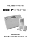
X10 HOME SECURITY
DS18
MS18
KR18
SH600
Door/Window Sensor
Motion Sensor
Key fob Remote
System Remote Control
USING THE DOOR/WINDOW SENSOR
1. Open the casing.
2. Ins ert batteries (2xAAA, alkaline) into the battery compartment. Observe
polarity.
3. Set the switch for entry delay (5) to MIN when you have installed the
sensor on a window and on MAX when the sensor is installed on a door.
When the switch is set to MAX, you have time to open and close the door
without triggering the alarm. If you want an instant alarm (on e.g. the
backdoor), set the switch to MIN.
4. Activate the sensor by pressing the tamper contact ( 6) on the transmitter
for 4 seconds. Release the button. The door/window sensor has now
chosen a unique code, which can be registered with your console.
REGISTER THE DOOR/WINDOW SENSOR
You need to register the DS18 door/window sensor with your
HomeGuard/Protector+ system. Your system’s user guide will show you
how to do this. If you do not have a user guide at hand, you can download
one from www.bmb-home.com.
DS18 DOOR / WINDOW SENSOR
1
2
3
4
5
6
4
7
8
ADDING A WIRED SENSOR TO THE DOOR/WINDOW SENSOR
The DS18 Door/Window Sensor has a contact for an extra wired s ensor.
These sensors need to be of type NC (normally closed contacts) and there
should not be any power on this contact (potential-free).
1. Open the transmitter part of the DS18.
2. Remove the wire bridge from the connection for the wired sensor (8).
3. Connect your additional sensor.
The wired contact can have its dedicated zone registration on the Security
Base Console. You can register the contact using the procedure as
described in your manual. To register the sensor, trigger the alarm of your
wired sensor while in registry mode.
ü The setting of the MIN/MAX switch (entry delay) of the DS18 is valid for
both the magnetic contact and the wired sensor.
TÜR-/FENSTERSENSOR DS1818
1. Senderteil.
2. Kontrollindikator – Wird die Sabotagekontakt Taste gedrückt, oder wird
ein Signal zur Zentrale versendet, leuchtet das LED auf. Wird das Licht
des LED schwächer, müssen die Batterien gewechselt werden.
3. Magnetkontakt – Der Abstand zwischen Magnet und Kontact darf
höchstens 5 mm betragen. Bei der Montage müssen die Pfeile auf den
Kontakten aufeinander gerichtet sein.
4. Schraubenlöcher für die Montage des Sensors.
5. Schalter für die Ankunftsverzögerung – Zum Einstellen der
Eintrittsverzörgerung von ca. 30 Sek.
6. Sabotagekontakt.
7. Batteriehalter
8. Anschluss für zusätzlichen drahtgebundenen Kontakt.
INBETRIEBNAHME DES TÜR-/FENSTERSENSORS
1. Sollten Sie das Gehäuse des Sensors noch nicht geöffnet haben, dann
tun Sie es jetzt.
2. Legen Sie die Batterien (2xAAA, Alkaline) in das Batteriefach ein.
Achten Sie dabei auf die Polarität (+/ -).
3. Wenn Sie den Sensor an einem Fenster montiert haben, stellen Sie den
Schalter für die Ankunftsverzögerung (5) auf den Stand MIN und bei einer
Zugangstür auf MAX. Wenn der Schalter auf MAX steht, erhalten Sie
genügend
Zeit um ins Haus zu gelangen und das System auszuschalten, ohne dass
der Alarm ausgelöst wird. Wenn Sie wollen, dass der Alarm unmittelbar
reagiert (z.B. Gartentür), dann lassen Sie den Schalter auf MIN eingestellt.
4. Drücken den Sabotagekontakt des Senders (6) 4 Sekunden lang.
Lassen Sie die Taste los. Der Tür-/Fenstersensor hat nun einen eigenen
einzigartigen Code gewählt, mit der Sie ihn bei der Zentrale anmelden
können.
DEN TÜR-/FENSTERSENSOR MIT IHREM SYSTEM NUTZEN
Sie
müssen
den
DS18
Tür-/Fenstersensor
bei
Ihrem
HomeGuard/Protector+ System anmelden. Wie dies vor sich geht, finden
Sie in der Gebrauchsanweisung nicht bei der Hand, so können Sie diese
über www.bmb-home.com downloaden.
ERWEITERN
DES
TÜR-/FENSTERSENSORS
MIT
EINEM
DRAHTVERBUNDENEN SENSOR
Der DS18 Tür-/Fenstersensor verfügt über einen Kontakt, an den Sie
einen drahtverbundenen Sensor anschließen können. Diese Sensoren
müssen vom Typ NC (normally closed, normal geschlossener Kontakt)
sein. Auf diesen Eingängen darf sich keine Spannung befinden (Potential
frei).
1. Öffnen Sie den Senderteil des DS18.
2. Nehmen Sie die Drahtbrücke aus dem Anschluss für den
drahtgebundenen Sensor (8).
Schließen Sie Ihren Sensor an.
3. Der drahtgebundene Kontakt erhält in der Zentrale eine eigene Zone.
Lösen Sie zur Anmeldung des Sensors während des Anmeldens mit Ihrem
verkabelten Sensor einen Alarm aus.
üDie Einstellung des MIN/MAX-Schalters (Ankunftsverzögerung) des
DS18 gilt sowohl für den Magnetkontakt wie für den drahtgebundenen
Sensor.
DOOR/WINDOW SENSOR DS18
1. Transmitter part – Built-in antenna.
2. Control indicator LED – When pressing the Tamper contact button, or
when the unit is transmitting a signal to the base station, this LED will light
up. When the LED blinks weakly, batteries have to be replaced.
3. Magnet contact – The distance between magnet and contact may not be
more than 5mm. When mounted, make sure the small arrows on the
magnet and the transmitter base part are lined up.
4. Screw holes for mounting the sensor.
5. Switch for entry delays – For setting a delay time of approximately 30
seconds.
6. Tamper contact.
7. Battery compartment.
8. Connection for extra wired contact.
HOME SECURITY
DEUR-/RAAMSENSOR DS18
1. Zenderdeel – ingebouwde antenne.
2. Controle indicator – Wanneer de sabotage contact toets wordt
ingedrukt, of wanneer er een signaal naar de centrale wordt verzonden,
gaat de indicator branden. Indien de indicator zwak brandt, dienen de
batterijen te worden vervangen.
3. Magneetcontact – De afstand tussen de magneet en het zenderdeel
mag hoogstens 5mm bedragen. Bij montage moeten de pijltjes op de
contacten recht tegenover elkaar staan.
4. Schroefgaatjes voor montage van de sensor.
5. Schakelaar voor aankomstvertraging – Voor het instellen van een
inloopvertraging van ong. 30 sec.
6. Sabotagecontact.
7. Batterijhouder.
8. Aansluiting voor extra draadgebonden contact of sensor.
IN GEBRUIK NEMEN VAN DE DEUR/RAAMSENSOR
1. Open de behuizing door de twee delen van elkaar te halen.
2. Plaats de batterijen (2xAAA, Alkaline) in de batterijhouder. Let hierbij op
de polariteit.
3. Zet de schakelaar voor aankomstvertraging (5) in de stand MIN
wanneer u de sensor op een raam heeft gemonteerd, en op MAX wanneer
u de sensor op een toegangsdeur heeft gemonteerd. Wanneer de
schakelaar op MAX staat krijgt u de tijd om uw huis binnen te komen en
het systeem uit te schakelen zonder dat het alarm afgaat. Wanneer u wilt
dat het alarm onmiddellijk reageert (b.v. schuifpui) laat u de schakelaar op
MIN staan.
4. Druk gedurende 4 seconden op het sabotagecontact (6) van de zender.
Laat de toets los. De deur/raamsensor heeft nu een eigen unieke code
gekozen die aangemeld kan worden bij de centrale.
DE DS18 DEUR/RAAMSENSOR GEBRUIKEN MET UW SYSTEEM
U dient de DS18 deur/raamsensor aan te melden bij uw
HomeGuard/Protector+ systeem. Hoe u dit doet kunt u terugvinden in de
gebruiksaanwijzing van uw systeem. Wanneer u de gebruiksaanwijzing
niet bij de hand heeft, kunt u deze downloaden via www.bmb-home.com.
UITBREIDEN VAN DE DEUR/RAAMSENSOR DS18 MET EEN
DRAADGEBONDEN SENSOR
De DS18 deur/raamsensor heeft een contact waar u een draadgebonden
sensor kunt aansluiten. Deze sensoren moeten van het type NC (normally
closed, normaal gesloten contact) zijn. Op het contact mag geen spanning
staan (potentiaal vrij).
1. Open het zenderdeel van de DS18.
2. Verwijder de draadbrug uit de aansluiting voor de draadgebonden
sensor (8).
3. Sluit de sensor aan. Het draadgebonden contact krijgt een eigen zone
op de centrale. Aanmelden doet u op dezelfde wijze als beschreven in de
gebruiksaanwijzing van uw systeem. Om de sensor aan te melden maakt
u op het moment van aanmelden een alarmmelding met uw
draadgebonden sensor.
ü?
De instelling van de MIN/MAX-schakelaar (inloopvertraging) van de
DS18 geldt zowel voor het magneetcontact als voor de draadgebonden
sensor.
DÉTECTEUR PORTE/FENÊTRE DS18
1. Partie émettrice.
2. Indicateur de contrôle – Quand vous appuyer sur le bouton contact antisabotage ou quand un signal est émis à la console, le LED s’allume. Si le
LED s’allume très faiblement, il faut remplacer les piles.
3. Contact magnétique – La distance entre les deux éléments ne peut être
supérieure à 5mm. Sur le montage, les contacts doit être fixer avec les vis.
4. Logements de vis pour le montage du détecteur.
5. Sélecteur pour temporisation d’entrée – Pour régler la temporisation
d’entrée de 30 sec .
6. Contact anti-sabotage.
7. Compartiment à piles.
8. Branchement pour un contact câblé supplémentaire.
MISE EN SERVICE DU DÉTECTEUR PORTE/FENÊTRE
1. Si vous n’avez pas encore ouvert le boîtier, faites-le maintenant.
2. Insérez les piles (2 piles AAA, alcalines) dans le compartiment à piles.
Respectez la polarité.
3. Mettez le sélecteur de temporisation d’entrée (5) en position MIN si
vous avez monté le détecteur sur une fenêtre et en position MAX si le
détecteur a été monté sur une porte d’entrée. Quand le sélecteur est
positionné sur MAX, vous avez le temps d’entrer dans la maison et de
désactiver le système sans que l’alarme se déclenche. Si vous désirez
que l’alarme réagisse tout de suite (ex. porte de jardin), il faut laisser e
l
sélecteur en position MIN.
4. Appuyez pendant 4 secondes sur le contact anti-sabotage (6) de
l’émetteur. Lâchez la touche. Le détecteur porte/fenêtre s’est à présent
choisi un code unique, que vous pouvez initialiser pour que votre console
le reconnaisse.
UTILISER LE DÉTECTEUR PORTE/FENÊTRE DS18 AVEC VOTRE
SYSTÈME
Vous devez initialiser le détecteur porte/fenêtre DS18 pour que votre
système HomeGuard/Protector+ puisse le reconnaître. Pour cela, veuillez
vous référer au mode d’emploi de votre système. Si vous n’avez pas le
mode d’emploi à portée de la main, vous pouvez le télécharger à partir du
site Internet www.bmb-home.com .
EXTENSION DU DÉTECTEUR PORTE/FENÊTRE DS18 AVEC UN
DÉTECTEUR CÂBLÉ
Le détecteur porte/fenêtre DS18 est muni d’un contact sur lequel un
détecteur câblé peut être branché. Ces détecteurs doivent être du type NF
(contact normalement fermé). Le contact ne doit pas se trouver sous
tension (libre de potentiel).
1. Ouv rez la partie émettrice du DS18.
2. Enlevez le fil de pont de la connexion pour le détecteur câblé (8).
3. Branchez votre détecteur. Le détecteur câblé a sa propre zone sur la
console. Pour initialiser le détecteur, vous devez provoquer une alarme en
utilisant votre détecteur câblé au moment de l’initialisation.
ü?
Le réglage du commutateur min/max (temporisation d’entrée) du DS18
est valable aussi bien pour le contact magnétique que pour le détecteur
câblé.
SENSOR DE PORTA/JANELA DS18
1. Transmissor – Antena embutida.
2. LED indicador de controlo – Ao pressionar o interruptor de Tamper ou
quando a unidade está a transmitir um sinal para a consola, este led
acende-se. Quando o LED piscar deve mudar as baterias.
3. Contacto magnético – A distancia entre o contacto e o íman não deve
ser superior a 5mm: Quando montados as setas pequenas do transmissor
e do íman deverão estar alinhadas.
4. Orifícios de fixação do sensor.
5. Selector de atrasos de entrada – Para seleccionar um atraso de entrada
de 30s.
6. Contacto de tamper.
7. Compartimento de baterias.
8. Entrada para um contacto por fios extra.
COMO UTILIZAR O SENSOR DE PORTA/JANELA
1. Abrir a tampa do sensor.
2. Inserir as baterias (2x AAA alcalinas) no compartimento das baterias.
Ter atenção com a polaridade das baterias.
3. Configure o atraso de entrada (5) na posição MIN se instalar o sensor
numa janela e na posição MAX se instalar o sensor numa porta. Quando o
selector de atraso de entrada está configurado na posição MAX, você tem
tempo para abrir e fechar a porta sem que o alarme dispare. Se pretender
que o alarme seja instantâneo (por exemplo, para proteger a porta das
traseiras) deve seleccionar a posição MIN.
4. Active o sensor pressionando o contacto de tamper (6) do transmissor
durante 4 segundos. Solte o contacto. Ao fim deste tempo o sensor de
porta/janela escolheu um código de identificação único, podendo ser
registado na consola.
REGISTAR O SENSOR DE PORTA/JANELA
É necessário registar o sensor de porta/janela DS18 com o seu sistema
Homeguard ou Protector+. O manual de instalação do seu sistema de
segurança indicar-lhe-á como fazer o registo dos sensores. Se não
possuir o manual do seu sistema de segurança. Pode fazer o download do
mesmo em: www.bmb-home.com .
ADICIONANDO UM SEN SOR POR CABO AO SENSOR DE PORTA
JANELA.
O sensor DS18 possui um contacto extra para a ligação de um sensor por
fios. Estes sensores necessitam ser do tipo normalmente fechado (NC ou
NO), não deve haver nenhum tipo de alimentação neste contacto (sem
potencial).
1. Abra a tampa do transmissor DS18.
2. Remova o fio que liga as duas entradas de sensor por cabo (8).
3. Ligue o sensor adicional. O sensor por cabo pode ter a sua zona
dedicada para o registo na consola de segurança. Você pode registar o
sensor utilizando o procedimento descrito no seu manual. Para registar o
sensor por cabo terá que fazer com que este dispare enquanto a consola
está no modo de registo de sensores.
üA configuração do selector de atraso de entrada do sensor DS18 é
valido para o contacto magnético e para o sensor por cabo.
TECHNICAL DATA:
Power:
RF range:
Dimensions:
RF Frequency:
USING THE MOTION DETECTOR
1. Open the battery compartment and insert the batteries (2x AA, alkaline).
2. Keep the TEST button (6) pressed for about 4 seconds. The LED will
flash once. Release the button. The LED will flash twice. The motion
detector has now chosen a unique code, which can be registered with your
console.
USING THE MS18 MOTION DETECTOR WITH YOUR SYSTEM
You need to register the MS18 motion detector with your Protector+
system. Your system’s user guide will show you how to do this. If you do
not have a user guide at hand, you can download one from www.bmbhome.com .
TEST MODE: TESTING THE LOCATION OF YOUR MOTION
DETECTOR
1. Set the switch (5) to 1.
2. Press the TEST button (6) until the indicator (1) flashes twice.
3. Wait 20 seconds.
4. Walk in front of the sensor. The indicator (1) lets you know when a
movement has been detected. This allows you to check whether the
sensor has been mounted on the right place.
5. Press the TEST button again to be able to use the sensor as normal.
ü After 2 minutes the motion detector will go back to the normal mode.
BEWEGUNGSMELDER MS18
1. Kontrollindikator - Leuchtet auf, wenn ein Signal versendet wird.
2. PIR
3. Sabotage Kontakt.
4. Batteriefach
5. Empfindlichkeitsschalter 1 /2 - Im Stand 1 reagiert der Sensor sofort auf
eine Bewegung, im Stand 2 ist der Sensor weniger empfindlich und
reagiert erst nach dem Erkennen einer zweiten Bewegung.
6. TEST-Taste
INBETRIEBNAHME DES BEWEGUNGSMELDERS
1. Öffnen Sie das Batteriefach und legen Sie die Batterien (2xAA, Alkaline)
ein.
2. Drücken die TEST-Taste (6) für 4 Sekunden. Die LED -Anzeige blinkt
einmal. Lassen Sie die Taste los. Die LED -Anzeige blinkt zweimal. Der
Bewegungsmelder hat nun einen eigenen einzigartigen Code gewählt, mit
der Sie ihn bei der Zentrale anmelden können.
2x AAA battery
15 - 30m through walls and floors
76x100x42mm
433,92 MHz
DEN MS18 BEWEGUNGSMELDER MIT IHREM SYSTEM NUTZEN
Sie müssen den MS18 Bewegungsmelder bei Ihrem Protector+ System
anmelden. Wie dies vor sich geht, finden Sie in der Gebrauchsanweisung
Ihres Systems. Haben Sie die Gebrauchsanweisung nicht bei der Hand, so
können Sie diese über www.bmb-home.com downloaden.
MS18 MOTION SENSOR
TESTMODUS: DEN STANDORT DES BEWEGUNGSMELDERS
TESTEN
1. Stellen Sie den Schalter (5) auf den Stand 1.
2. Drücken Sie die TEST-Taste (6), bis der Indikator (1) zweimal blinkt.
3. Warten Sie 20 Sekunden.
4. Laufen Sie vor dem Sensor vorbei. Der Indikator (1) zeigt es jedes Mal
an, wenn eine Bewegung erkannt wird. Auf diese Weise können Sie
kontrollieren, ob der Sensor an der richtigen Stelle montiert wurde.
5. Drücken Sie nochmals auf die TEST-Taste, um wieder zum
Normalbetrieb zurückzukehren.
ü Der Bewegungsmelder kehrt nach 2 Minuten automatisch in den
Normalbetrieb zurück
1
2
3
4
MS18 BEWEGINGSMELDER
1. Controle indicator - Licht op wanneer er een signaal wordt verzonden.
2. PIR
3. Sabotage contact.
4. Batterijvak.
5. Gevoeligheidsschakelaar 1 / 2 - In stand 1 reageert de sensor direct op
beweging, in stand 2 is de sensor minder gevoelig en reageert de sensor
pas na het zien van meerdere bewegingen.
6. TEST-toets.
5
IN GEBRUIK NEMEN VAN DE BEWEGINGSMELDER
1. Open het batterijvak en plaats de batterijen (2x AA, alkaline).
2. Druk gedurende 4 seconden op de TEST toets (6). De LED knippert 1x.
Laat de toets los. De LED knippert 2x. De bewegingsmelder heeft nu een
eigen unieke code gekozen die aangemeld kan worden bij uw centrale.
6
DE MS18 BEWEGINGSMELDER GEBRUIKEN MET UW SYSTEEM
U dient de MS18 bewegingsmelder aan te melden bij uw Protector+
systeem. Hoe u dit doet kunt u terugvinden in de gebruiksaanwijzing van
uw systeem. Wanneer u de deze niet voorhanden heeft, kunt u deze
downloaden via www.bmb-home.com .
TESTMODE: DE LOCATIE VAN UW BEWEGINGSMELDER TESTEN
1. Zet de schakelaar (5) in stand 1. Druk op de TEST toets (6) totdat de
indicator (1) twee maal knippert.
3. Wacht 20 seconden.
4. Loop voor de sensor door. De indicator (1) geeft telkens aan als er een
beweging wordt gedetecteerd. Op deze wijze kunt u controleren of de
sensor op de juiste plaats is gemonteerd.
5. Druk nogmaals op de TEST toets om terug te keren naar normaal
bedrijf.
ü De bewegingsmelder keert na 2 minuten automatisch terug naar
normaal bedrijf.
MOTION DETECTOR MS18
1. Control Indicator - Lights up when a signal is transmitted.
2. PIR
3. Tamper contact.
4. Battery compartment.
5. Sensitivity switch 1/2 - In setting 1 the sensor will instantly react to
movement, in setting 2 the sensor is less sensitive and will only react after
registering multiple movements.
6. TEST button.
DÉTECTEUR VOLUMÉTRIQUE MS18
1. Indicateur de contrôle - s’allume lorsqu’un signal est émis.
2. PIR
3. Contact anti-sabotage.
4. Compartiment à piles
5. Commutateur sensibilité 1 / 2 - En position 1, le détecteur réagit tout de
suite à un mouvement; en position 2, le détecteur est moins sensible et ne
réagit qu’après avoir détecté deux mouvements.
6. Touche TEST
REV. 11-07-05
MISE EN SERVICE DU DÉTECTEUR VOLUMÉTRIQUE
1. Ouvrez le compartiment à piles et insérez les piles. (2 piles AA,
alcalines)
2. Appuyez pendant 4 secondes sur la touche TEST (6). Le DEL clignote
une fois. Lâchez la touche. Le DEL clignote deux fois. Le détecteur
volumétrique s’est à présent choisi un code unique, que vous pouvez
initialiser pour que votre console le reconnaisse.
UTILISER LE DÉTECTEUR VOLUMÉTRIQUE MS18 AVEC VOTRE
SYSTÈME
Vous devez initialiser le détecteur volumétrique MS18 pour que votre
système Protector+ puisse le reconnaître. Pour cela, veuillez vous référer
au mode d’emploi de votre système. Si vous n’avez pas le mode d’emploi
à portée de la main, vous pouvez le télécharger à partir du site Internet
www.bmb-home.com .
MODE TEST : TESTER L’EMPLACEMENT DE VOTRE DÉTECTEUR
VOLUMÉTRIQUE
1. Mettez le commutateur (5) en position 1
2. Appuyez sur la touche TEST (6) jusqu’à ce que l’indicateur (1) clignote
deux fois.
3. Attendez 20 secondes.
4. Passez devant le détecteur. L’indicateur (1) signale chaque mouvement
détecté. De cette façon, vous pouvez vérifier si le détecteur a été monté
au bon endroit.
5. Appuyez de nouveau sur la touche TEST pour retourner au
fonctionnement normal.
ü Après 2 minutes, le détecteur volumétrique retourne automatiquement
au fonctionnement normal.
DETECTOR DE MOVIMENTO MS18
1. Led indicador de controlo – Quando a unidade está a transmitir um sinal
para a consola, este led acende-se.
2. PIR
3. Contacto de tamper.
4. Compartimento das baterias.
5. Selector de sensibilidade – Na posição 1 o sensor reage imediatamente
à detecção de movimento, na posição 2 o sensor não é tão sensível (só
reage quando detecta dois movimentos).
6. Botão de teste.
COMO UTILIZAR O SENSOR DE PORTA/JANELA
1. Abrir o compartimento das baterias e inserir as baterias (2xAA
alcalinas).
2. Mantenha o botão TEST premido durante 4 segundos. O LED vai piscar
uma vez. Solte o botão de teste. O LED piscará duas vezes. Ao fim deste
tempo o sensor de porta/janela escolheu um código de identificação único,
podendo ser registado na consola.
REGISTAR O SENSOR DE PORTA/JANELA
É necessário registar o sensor de movimento MS18 com o seu sistema
Protector+. O manual de instalação do seu sistema de segurança indicarlhe-á como fazer o registo dos sensores. Se não possuir o manual do seu
sistema de segurança. Pode f azer o download do mesmo em: www.bmbhome.com .
MODO DE TESTE: TESTAR A LOCALIZAÇÃO DO SEU DETECTOR DE
MOVIMENTO
1. Coloque o selector de sensibilidade (5) na posição 1.
2. Carregue no botão TEST (6) até que o LED pisque duas vezes.
3. Espere 20 segundos
4. Caminhe à frente do sensor. O LED (1) indica-lhe quando é que foi
detectado movimento. Isto permite-lhe testar se o sensor foi instalado no
local certo.
5. Carregue no botão TEST outra vez, para que o sensor volte a funcionar
normalmente.
ü Ao fim de dois minutos o sensor volta ao modo de funcionamento
normal.
TECHNICAL DATA:
Power:
RF range:
PIR range:
Dimensions:
RF Frequency:
2x AA battery
15 - 30m through walls and floors
12m, 90°
76x100x42mm
433,92 MHz
KR18 KEYFOB REMOTE CONTROL
1
2
6/7
3
4
5
8
ACTIVAR O KR18
Carregue na tecla de Arm durante 3 segundos e largue a tecla, o Led
indicador de controlo pisca.
KR18 REMOTE CONTROL
CONTROLS:
1. Control indicator: Comes on when the remote control sends a radio
signal when keys are pressed. When the indicator blinks only weakly, the
batteries have to be replaced.
2. Arm: Switches on the Security System in the Arm Away mode. All
sensors are activated.
3. Disarm: Switches off the Security System.
4. A On / Off: Switches on / off the lights connected to the Lamp Module
set to the Home Automation base address.
5. B On / Off: Switches on / off the lights connected to the Lamp Module
set to the Home Automation base address +1.
6/7. Panic: When both keys ARM (2) and DISARM (3) are pressed
simultaneously, an immediate alarm is initiated by the Security System.
8. Battery holder: The back of the remote can be easily opened. Use 2
CR2016, 3V lithium batteries.
TECHNICAL DATA:
Power:
RF range:
Dimensions:
RF Frequency:
2x CR2016 Lithium
15 - 30m through walls and floors
61x35x15mm
433,92 MHz
SH600 SYSTEM REMOTE CONTROL
1
2
3
ACTIVATING THE KR18
Push the Arm key for more than 3 seconds and release the button; the
indicator blinks.
KR18 FERNBEDIENUNG
BEDIENUNGSELEMENTEN:
1. Kontroll LED: Brennt wenn die Fernbedienung beim Drücken von
Tasten Radiosignale versendet. Brennt das LED nur noch schwach,
müssen die Batterien erneuert werden.
2. Arm: Schaltet den Alarm in die Arm Away funktion. Alle Sensoren sind
aktiv.
3. Disarm: Schaltet das Alarmsystem aus.
4. A On / Off: Schaltet das Lampenmodule mit der Home Automation
basis Adresse an / aus.
5. B On / Off: Schaltet das Lampenmodule mit der Home Automation
basis Adresse + 1 an / aus.
6/7. Panik: Werden die Tasten ARM (2) und DISARM (3) gleichzeitig
gedrückt, wird sofort der Panikalarm aktiviert.
8. Batteriefach: Die Rückseite der fernbedienung ist einfach zu öffnen.
Verwenden Sie zwei 3V Lithium -Batterien Typ CR2016.
IN BETRIEB NEHMEN:
Länger als 3 secunden die ARM Taste drücken, dann loslassen; Das LED
blinkt.
KR18 AFSTANDSBEDIENING
BEDIENINGSELEMENTEN :
1. Controle indicator: Brandt wanneer de afstandsbediening bij het
indrukken van de toetsen radiosignalen uitzendt. Wanneer de indicator
nog maar zwak brandt, dienen de batterijen vervangen te worden.
2. Arm: Schakelt het alarm aan in de Arm Away functie (alle sensoren zijn
actief).
3. Disarm: Schakelt het beveiligingssysteem uit.
4. A On / Off: Schakelt de lamp die aangesloten is op de Lampmodule
met het Home Automation basisadres aan / uit.
5. B On / Off: Schakelt de lamp die aangesloten is op de Lampmodule
met het Home Automation basisadres + 1 aan / uit.
6+7. Panic: Wanneer de toetsen ARM (2) en DISARM (3) gelijktijdig
worden ingedrukt, wordt direct het paniek alarm geactiveerd.
8. Batterijhouder: De achterzijde van de afstandsbediening kan
gemakkelijk geopend worden. Gebruik 2 CR2016, 3V lithium batterijen.
IN GEBRUIK NEMEN:
Druk langer dan 3 seconden op de ARM toets, en laat de toets daarna los;
De LED knippert.
KR18 TELECOMMANDE
ELEMENTS DE COMMANDE:
1. Contrôle LED: S’allume quand on appuie les boutons de la
télécommande. Quand la LED s’allume très faiblement, il faut remplacer la
pile.
2. Arm ON: Active l’alarme dans le mode Arm Away. Tous les détecteurs
sont activés.
3. Arm Off: Désactive le système d’alarme.
4. A On / Off: Active / Désactive les lumières connectées à un Module
Lampe avec une adresse de base Home Automation.
5. B On / Off: Active / Désactive les lumières connectées à un Module
Lampe avec une adresse de base Home Automation +1.
6/7. Panique: En appuyant simultanément sur les touches ARM (2) et
DISARM (3), l’alarme panique est immédiatement activée.
8. Compartiment piles: L’arrière de la télécommande s’ouvre facilement.
Utilisez uniquement 2 piles du type lithium 3V CR2016.
MISE EN SERVICE:
Appuyer sur la touche ARM pendant plus d’une seconde jusqu’à ce que
l’indicator lumineux clignote fois.
HOME SECURITY
CONTROLO REMOTO KR18
TECLAS:
1. Led indicador de controlo: Liga-se quando se carrega uma tecla do
controlo remoto e se envia um sinal de rádio. Quando a intensidade
luminosa é baixa, as baterias do controlo remoto devem ser substituídas.
2. Arm: Liga o sistema de segurança no modo de Arm Away. Todos os
sensores são activados.
3. Disarm: Desliga o sistema de segurança.
4. A On/Off: Liga/desliga todas as lâmpadas ligadas aos módulos de
lâmpadas configurados com o endereço base.
5. B On/Off: Liga/desliga todas as lâmpadas ligadas aos módulos de
lâmpadas configurados com o endereço base+1.
6/7. Panic: Quando ambas as teclas ARM (2) e DISARM (3) são premidas
em simultâneo é gerado um alarme imediato no sistema de segurança.
8. Suporte das baterias: A parte de trás do controlo remoto é fácil de abrir.
Use duas baterias de 3V CR2016 de lítio.
6. Selector de código de casa: Usado para seleccionar o código de casa
do sistema.
7. Janela de anotações: Na etiqueta de papel por detrás do plástico
transparente pode escrever quais os endereços controlados por cada
tecla do comando.
INBETRIEBNAHME:
- Das Bettriefach an der Rüchseite der Fernbedienung öffnen und die
Batterien einlegen (4x AAA, vorzugdweise Alkalinebatterien).
- Drüchen Sie die Paniktaste (1) bis das Kontroll LED leuchtet. Den
Schalter auf Stand SEC stellen.
TECHNICAL DATA:
Power:
RF range:
Dimensions:
RF Frequency:
SH600 SYSTEEMAFSTANDSBEDIENING
BEDIENINGSELEMENTEN
1. Panic: Met deze toets wordt direct het paniek alarm ingeschakeld.
2. Controle indicator: Brandt wanneer de afstandsbediening bij het
indrukken van de toetsen radiosignalen uitzendt. Wanneer de indicator
nog maar zwak brandt, dienen de batterijen vervangen te worden.
3. Bedieningstoetsen: Voor het bedienen van het Beveiligingssysteem en
voor het bedienen van Home Automation Modules.
4. Dimtoets: Voor het regelen van de verlichtingsterkte van verlichting
welke is aangesloten op Lampmodules.
5. Modusschakelaar: Door de stand van deze schakelaar kunnen de
bedieningstoetsen een andere functie krijgen.
Stand SEC: Hiermee krijgen de bovenste drie knoppen de alarmfuncties
zoals beschreven op de afstandsbediening. De vijf toetsen daaronder
(1….5) voor het schakelen van Home Automation Modules met
overeenkomstig adres (UnitCode 1 t/m 5).
Stand 1: 1…8: voor het schakelen van Home Automation Modules met
overeenkomstig adres (UnitCode 1 t/m 8).
Stand 2: 9…16: voor het schakelen van Home Automation Modules met
overeenkomstig adres (UnitCode 9 t/m 16).
6. HuisCode schakelaar: Voor het instellen van het systeemadres.
7. Tekstvenster: Op het formulier in dit tekstvenster kunt u noteren welke
Home Automation Modules met de verschillende toetsen worden bediend.
KR28 PERSONAL ASSISTANT KEYCHAIN REMOTE
Additional Pendant Transmitter for Personal Assistance Voice Dialler. Main
Console emits siren, begins dialling up to 6 telephone numbers and
flashes the Lamp Modules. The party answering the call can press "0" and
listen in. Sends an emergency voice message to: pagers, cellular phones,
offices,
authorities,
relatives,
or
friends…
Ideal for: assistance, protection & security, or anywhere that requires
immediate emergency notification. Remote receives phone calls and dials
out direct access phone numbers by a press of a button.
IN BEDRIJF STELLEN:
- Open de batterijhouder aan de achterzijde van de afstandsbediening en
plaats de 4 AAA batterijen, bijvoorkeur Alkaline, in de houder. Let op
polariteit.
- Druk op de Panic toets (1) totdat de controle indicator gaat branden.
Schakel de keuzeschakelaar in de stand SEC.
7
4
6
Stand SEC: Hiermit erhalten die drei obersten Taste der Alarmfunktionen,
wie au der Fernbedienung beschrieben. Die fünf Tasten darunter (1...5)
zum Schalten von Haus Automations Modulen mit übereinstimmender
Adresse (UnitCode 1 bis 5).
Stand 1: 1…8: Zum schalten von Home Automation Modulen mit
entsprechender Adresse (Unit Code 1 t/m 8)
Stand 2: 9…16: Zum schalten von Home Automation Modulen mit
entsprechender Adresse (Unit Code 9 t/m 16)
6. HausCodesch alter: Zum einstellen der Systemadresse.
7. Textfenster: Auf dem Formular in diesem Textfenster können sie
notieren, welche Home Automation Module mit den verschiedenen Tasten
bediend werden.
5
SH600 SYSTEM REMOTE CONTROL
CONTROLS
1. Panic: When this key is pressed, an immediate alarm will be initiated by
the Security System
2. Control indicator: Comes on when the remote control sends a radio
signal when keys are pressed. When the indicator blinks only weakly, the
batteries have to be replaced.
3. Control keys: To control the Security System and the Home
Automation Modules.
4. Dimming Key: To control the light level of lamps which are connected
to Lamp Modules.
5. Mode switch: The position of this switch defines the functions of the
control keys.
Position SEC: The top three buttons get the alarm function as described
on the remote control. The next 5 buttons (1…5) are for controlling Home
Automation Modules with corresponding addresses. (Unit Code 1 t/m 5).
Position 1: 1…8: For controlling Home Automation Modules with
corresponding addresses. (Unit Code 1 t/m 8).
Position 2: 9…16: For controlling Home Automation Modules with
corresponding addresses. (Unit Code 9 t/m 16).
6. House Code switch: Used for setting the system address.
7. Text window: On the piece of paper behind the plastic cover of the text
window, you can note which Home Automation Modules can be controlled
with each key.
INSTALLATION:
- Open the battery compartment on the back of the remote control and
place the battery (4x AAA, preferably use alkaline batteries). Observe
polarity.
- Press the Panic key (1) until the control indicator comes on. Set the
mode switch to the SEC position.
SH600 SYSTEMFERNBEDIENUNG
BEDIENUNGSELEMENTEN:
1. Panik: Mit dieser Taste wird sofort der Panikalarm eingeschaltet.
2. Kontroll LED: Brennt wenn die Fernbedienung beim Drücken von
Tasten Radiosignale versendet. Brennt das LED nur noch schwach,
müssen die Batterien erneuert werden.
3. Tastatur: Zum Bedienen des Alarmsystems und zum Bedienen von
Haus Automation Modulen.
4. Dimmtaste: Zum Regeln der Lichtstärke von Lampen, die an die
Lampenmodule angeschlossen sind.
5. Modulschalter: Durch den Stand Schalters können die Tasten eine
andere Function bekommen.
SH600 TELECOMMANDE DOMOTIQUE
ELEMENTS DE COMMANDE:
1. Panique: En appuyant sur ce bouton, l’alarme se déclenche
automatiquement.
2. Contrôle LED: S’allume quand on appuie les boutons de la
télécommande. Quand la LED s’allume très faiblement, il faut remplacer la
pile.
3. Touche de commande: Pour commander le système d’alarme et les
Home Automation Modules.
4. Touche de variation: Pour le réglage de l’intensité des lumières qui
sont branchées sur les modules récepteur lampe.
5. Sélecteur de mode: En modifiant la position du curseur, on peut
changer la fonction des boutons de commande.
Position SEC: Les 3 touches du haut permettent d'activer les fonctions
d'alarme comme indiqué sur la télécommande. Les autre touches 1…5
pour contrôler les Home Automation Modules ayant leurs adresses
comprises de 1 à 5.
Position 1: 1..8 : Pour contrôler les Home Automation Modules ayant
leurs adresses comprises de 1 à 8.
Position 2: 9..16 : Pour contrôler les Home Automation Modules ayant
leurs adresses comprises de 9 à 16.
6. Sélecteur Code Maison: Pour adresser un Code Système.
7. Ecran texte: Vous pouvez identifier sur le formulaire de l’écran texte
par quel bouton, les Home Automation Modules sont Commandés.
MISE EN SERVICE DE LA TELECOMMANDE
- Ouvrir le capot du compartiment piles situé à l’arrière de la
télécommande. Insérez 4 piles de type AAA alcalines en respectant les
polarités.
- Appuyer sur le bouton panique (1) jusqu’à ce que le LED de contrôle
s’allume. Mettez le curseur (5) dans la position SEC.
CONTROLO REMOTO DO SISTEMA SH600
TECLAS
1. Pânico: Quando esta tecla é premida é gerado um alarme imediato no
sistema de segurança.
2. Arm: Liga o sistema de segurança no modo de Arm Away. Todos os
sensores são activados.
3. Teclas de controlo: Para controlar o sistema de segurança e os
módulos de domótica.
4. Tecla de “dimming”: Para controlar a intensidade luminosa de
lâmpadas ligadas a módulos de lâmpada.
5. Comutador de modo de funcionamento: A posição deste comutador
define as funções desempenhadas pelas teclas.
Posição SEC: Os três primeiros botões do comando executam as tarefas
descritas no comando. Os 5 botões seguintes controlam as
funcionalidades de domótica (códigos de unidade de 1 a 5).
Posição 1: 1…8: Controlam as funcionalidades de domótica do endereço
1 ao 8.
Posição 2: 9…16: Controlam as funcionalidades de domótica do
endereço 9 ao 16.
INSTALAÇÃO:
- Abra o compartimento das baterias na parte detrás do comando e insira
as baterias (4xAAA alcalinas). Tenha em atenção a polaridade das
baterias.
- Carregar na tecla Panic (1) até que o Led se acenda. Coloque o selector
de modo de funcionamento na posição SEC.
4x AAA Alkaline Batteries
15 - 30m through walls and floors
116x65x15mm
433,92 MHz
Registering the Pendant Remote with the Console
•
Enter the INSTALL menu on the Console.
•
Press EMERGENCY CALL. The console responds to confirm that
the pendant has been registered.
•
Return to normal operation, by exiting the menu of the console.
Testing the Pendant Remote
•
Put the Console in operation mode.
•
Press EMERGENCY CALL on the remote. The console is triggered,
the alarm sounds and the first number is dialled.
•
Press STOP to cancel the alarm.
Note: If the console has already started dialling out, it will finish dialling the
current number before cancelling the alarm.
PH7208 Extra siren for Security System
You can connect one or more extra Sirens to the Security System. With an Alarm Interface
(SM10) you can connect these Sirens also to other Security Systems.
Warning:
1. The Siren works on 230V. Do not open the housing – high voltage inside. Make sure you
unplug the PH7208 from the mains before installing.
2. The Siren produces an extreme loud sound (110dB). To prevent ear damage you should never
be near an active Siren.
How your PH7208 siren works:
The siren works without extra wiring. The commands to switch the siren on and off are sent
through the existing house wiring (X10 command "all lights on" and "all lights off"). These
commands are being placed on the existing house wiring by Alarm Systems or by an Interfa ce
SM10.
Note: the Siren has to be connected on the same phase as the alarm console.
To prevent false alarm the system waits a few seconds before triggering the Siren after activating
the Alarm. The Siren makes a piercing two-tone signal for 4 minutes when activated. After this
the Siren will be automatically switched off (or sooner when the alarm is switched off).
Note: When you use an Alarm System, the Sirens always work during an alarm, regardless of the
function silent alarm is being switched on. To activate the Siren the Unit Code and House Code
on the Alarm console or the Interface needs to be set up the same as the Siren. The standard
Code is A1.
Mounting PH7208: The Siren PH7208 is made for inside use. The PH7208 can be connected to
any power point.
SH10 Remote Chime for Security System
The Remote Chime is designed to work with the X10 Security Console or Home Controller to
provide a pleasant annunciator chime when someone approaches. It will also respond as Siren in
case the Security Console is activated. It can also be activated using the correct House Code
and Unit Code from any X10 controller.
Setting up the Remote Chime
1) Using a small screwdriver adjust the code wheels to the des ired House Code and Unit Code. If
the Remote Chime is to be used with the Security System, you should ensure that the House and
Unit Codes correspond to the Remote Chime settings (Base console address HC+1 Unit Code
5).
2) Plug the Remote Chime into a wall outlet.
Testing the Remote Chime from a Plug-in Controller: Press the ON button on a controller
corresponding to the House Code and Unit Code set on the Remote Chime.
How your SH10 siren works:
You can connect one or more extra Remote Chimes to the Security System. The chime/siren
works without extra wiring. The commands to switch the siren on and off are sent through the
existing house wiring (X10 commands). These commands are being placed on the existing house
wiring by Alarm Systems or Home Automatio n Controllers.
Note: the Remote Chime/Siren has to be connected on the same phase as the alarm console.
Mounting SH10: The Remote Chime SH10 is made for inside use only. The SH10 can be
plugged into to any wall outlet 230V 50Hz.
DECLARATION OF CONFORMITY
Hereby, X10 Europe, declares that th e DS18 / MS18 / KR18 / SH600 is in
compliance with the essential requirements and other relevant provisions of
Directive 1999/5/EC.
Hiermit erklärt X10 Europe die Übereinstimmung des Gerätes DS18 / MS18 /
KR18 / SH600 den grundlegenden Anforderungen und den anderen relevanten
Festlegungen der Richtlinie 1999/5/EG.
Bij deze verklaart X10 Europe, dat deze DS18 / MS18 / KR18 / SH600 voldoet
aan de essentiële eisen en aan de overige relevante bepalingen van Richtlijn
1999/5/EC.
Par la présente X10 Europe déclare que l'appareil DS18 / MS18 / KR18 / SH600
est conforme aux exigences essentielles et aux autres dispositions pertinentes
de la directive 1999/5/CE
X10 EUROPE
REV. 11-07-05