1
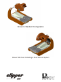
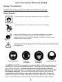
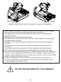
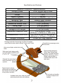
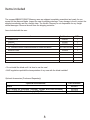
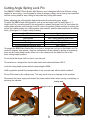
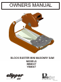
OWNERS MANUAL
BLOCK BUSTER MINI MASONRY SAW
MODELS
BBM307
YBM307
A PRODUCT OF NORTON COMPANY
Revised 9-2003
Shown In Standard Configuration
Shown With Dust Collecting & Dust Vacuum System
A PRODUCT OF NORTON COMPANY
WARRANTY
Norton warrants to the purchaser that each unit will be free from defects in
materials or workmanship for one hundred eighty (180) days from the original
purchase date from Norton when used for commercial, institutional or
professional use: or for thirty (30) days from the original purchase date from
Norton when used for rental purposes.
The responsibility of Norton under this warranty is limited to replacement or
repair of defective parts at a point designated by it, of such part as shall appear
to us upon inspection at such point, to have been defective in material or
workmanship, with expense for transportation borne by the customer.
In no event shall Norton be liable for consequential or incidental damages
arising out of the failure of any product to operate properly.
Integral units such as gasoline engines, electric motors, batteries, tires,
transmissions, etc., are excluded from this warranty and are subject to the
prime manufacturer's warranty.
This warranty is in lieu of all other warranties, expressed or implied, and all such
other warranties are hereby disclaimed.
Important: Before placing equipment in operation, record the following
information.
MODEL:_________ SERIAL NO.___________
PURCHASE FROM: _____________________
ADDRESS: ____________________________
CITY_______ STATE ______ ZIP ________
TELEPHONE NO. ______________________
Before using this equipment, make sure that the person using it has
read and understands the instructions in this owner’s manual.
WARNING:
The engine exhaust from this product
contains chemicals known to the State of
California to cause cancer, birth defects or
other reproductive harm
3
BBM307/YBM307
OWNER'S MANUAL
CONTENTS
Safety Precautions
PAGE
5-6
Specifications and Features
7
Items Included
8
Cutting Angle Spring Lock Pin
9
Dust Collection Pan
10
Conveyor Cart Assembly
11
Electric Motor
12
Electrical Safety
12-15
Carbon Brush
16
Air Filter
17
Conveyor Cart Assembly Figure 1
18
Conveyor Cart Assembly Figure 2
19
Frame and Dust Collecting Pan
20
Cutting Table Guide Rails
21
Cutting Table Assembly
22
Dust Guard Assembly (Optional)
23
Electrical System
24
Carbon Brush, Air In-take, and Blade Shaft
25-26
Cutting Head Assembly
27-28
Motor Assembly
29
Blade Guard Assembly
30
Optional Dust Collecting Assembly, Optional Stand
31
Optional Dry Cutting Kit
32
Read Owners Manual Before Use
Safety Alert Symbol: Information Following This Symbol Is Very Important.
4
Use Only Norton Diamond Blades
Safety Precautions
Important! The following safety precautions must always be observed.
Hazard Symbols
Keep all guards in place when operating any piece of equipment
Keep hands, feet, hair, and clothing away from all rotating parts
Never tamper with the governor components of settings to increase the
maximum speed. Severe personal injury and damage to the motor or
equipment can result if operated at speed above maximum. Always obey the
maximum speed rating of blade.
DO NOT LIFT THE SAW BY THE CUTTING HEAD OR HANDLE BAR
Use Approved:
Eye Protection
Hearing
Protection
Respiratory
Protection
Head Protection
The BBM307/YBM307 is designed as a masonry (Block, and Brick) saw and is not
designed for non-masonry classified material. Use steel center Diamond Blades
Only with this machine. For best preformance use steel center Diamond
Blades with a soft bond and a low diamond concentration that are specified
for masonry products. The use of blades with hard bonds or high diamond
concentration on this machine may result in damage to the motor. Clean and
replace the air filter as needed. Failure not to clean or replace the air filter may
result in motor damage. Do not use the machine without the air filter in place.
5
Lift Here
Lift Here
Machine Lifting Points: Only lift machine by the approved lifting points.
1. Before mounting any blade on the saw, the blade should be inspected for any damage
which might have occurred during shipment, handling or previous use.
2. The blade collars and arbors should be cleaned and examined for damage before
mounting the blade.
3. The blade must be properly fitted over the arbor.
4. The blade shaft nut, which is a left-hand thread nut, must be tightened securely against
the outside blade shaft collar.
5. The blade must be operated within the specified maximum operating speed listed on
the blade.
6. The blade guard must be in place with the blade collar guard closed when the saw
is running.
7. The operator should wear approved eye, hearing, respiratory, and head protection.
8. When starting the saw, the operator should stand away and to the side of the blade.
9. If for any reason the saw should stall in the cut, raise the blade out of the cut and switch the
power off. Check outside blade shaft collar and nut for tightness. Inspect the blade for
damage. Before restarting the saw. Use caution when resuming a cut. Be certain that the
blade is in alignment with the previous cut.
10. During cutting operations, do not exert excess side pressure on the material as a
method of guiding. Do not force the blade into the cut by lowering the blade too fast
or by pushing the cutting table too fast.
You Are Responsible For Your Safety!!!
6
Specifications and Features
BBM307/YBM307 Specifications
Horse Power
3 HP (2,238 kW) Peak
Volts
115 -volts
Amps
14 A
Hertz (Cycles)
60 Hz
Motor Type
Air Cooled Carbon Brush
Bearing Type
Heavy Duty Sealed
Blade Shaft Speed
3,600 rpm
Maximum Blade Size
14 in (356mm)
Arbor Size
1 in (25.4mm)
Maximum Depth of Cut
5 in (127mm)
Straight Cut Length
17 in (431mm)
Maximum Material Size
8 in x 8 in x 16 in
(203mm x 203mm x 406 mm)
Dimensions L x W x H
31-1/2 in x 18-1/2 in x 30 in
(800mm x 470mm x 762mm)
Weight Uncrated
75 lbs (34.1kg) Approx.
Pivoting head with dual springs and Posi-Loc allows
exact blade location when cutting 4" thick, and 8" thick
Powerful low amperage motor
with air filter
Arbor cover helps contain dust and
water
Ergonomically designed
Clear View Cutting Head
System: Provides increase
operator efficiency, reduce
fatigue, and provides a
unobstructed view of the
work area.
Wide open back design easily
accommodates materials up to
8" x 8" x 16”
Channel flow pan helps to
direct dust away from the
operator
Rigid all-steel unibody
construction provides the
best weight to strength ratio
of any saw in its class.
Front and rear handles
for easy transport and
loading.
Lockable heavy duty slide tray with
steel wheels and removal backstop
7
Items Included
The compact BBM307/YM307 Masonry saws are shipped completely assembled and ready for use
except for the diamond blade. Inspect the saw for shipping damage. If any damage is found, contact the
shipper immediately and file a freight claim. The Norton Company is not responsible for any freight
related damages. Remove the saw from the shipping container.
Items Included with the saw:
Item
Part Number
Guide-A-Cut
Wrench
Cutting Table
14” Genuine Norton Diamond Blade for Brick and Block
Extra Air Filter
234030
233041
235002
Call 1-800-554-8003
235035
QTY
1
1
1
1
1
• Do not install the blade until it is time to use the saw!
• ANSI regulations prohibit the transportation of any saw with the blade installed!
Optional Accessories (Purchased Separately)
Optional Accessories
Stand
Dry Cutting Kit (includes: Vacuum, Hoses, and Dust Shields)
Ground Fault Circuit Interrupt (GFI) 20A
8
Part Number
235001
235004
235000
Cutting Angle Spring Lock Pin
The BBM307/YBM307 Block Buster Mini Masonry saw is designed with three different cutting
heights for jam cutting, a moving head for chop (or plunge cutting), and a moving cart combined
with the moving head for step cutting to help make any cutting task easier.
Before adjusting the cutting height always disconnect the electrical power supply.
To adjust the BBM’s fixed cutting position, pull up on the Angle Lock Pin (see Figure 1-1:
Angle Lock Pin), move the head to the new position, release the Angle Lock Pin, and rotate the
cutting head up/down until the Angle Lock Pin locks into position (lowest position for cutting thru
bricks, the middle position for cutting medium size material, and the upper position is for cutting
block.) (See figure 1-2: Angle Locking Position).
Head Position
Fixed Lowest
Fixed Middle
Fixed Upper
Pivoting
Pivoting Head with Moving Table
Application
Jam Cutting Bricks
Jam Cutting Medium Size Bricks
Jam Cutting Block
Chop or Plunge Cutting
Step Cutting
To operate the BBM Block Buster Mini as a chop or plunge saw: pull up on the Angle Lock Pin,
rotate 90 degrees, and release. Now the cutting head can be rotated by pulling up or pushing
down on the cutting head handle. When not in use, always lock the head into one of the
three cutting height positions.
Do not install the blade until it is time to use the saw!
This machine is designed for the use with steel center diamond blades ONLY!
Lock the cutting head in place before transporting the BBM
ANSI regulations prohibit the transportation of any concrete saw with the blade installed!
Do not lift the saw by the cutting head. This may result in injury or damage to the machine.
Disconnect the power supply and lockout the power switch before when moving, maintaining, or
servicing the machine.
Cutting Head
Angle Lock Pin
Figure 1-1: Angle Lock Pin
9
Figure 1-2: Angle Locking Position
Dust Collection Pan
The Dust Collection Pan is assembled to the machine from the factory. The following procedure is
to remove or to replace the Dust Collection Pan Assembly:
1. Remove Conveyor Cart (see page 11 Conveyor Cart Assembly for instructions) and then remove
the four (4) sets of Hardware (Bolt, Lock Washer, and Washer) from each corner of the machine
frame and remove the rails from the frame (see Figure 2-1: Removing the Rails). Note the
orientation of the Hardware and the Rails.
2. Remove the Dust Pan Assembly from the frame (see Figure 2-2: Removing the Pan).
3. Replace the Dust Pan Assembly if required.
4. Replace the Rails (note that the leg with the mounting holes will face towards the outside of
the frame.
5. Replace the Hardware. Snug the operator’s left hand side and fully tighten the operators right
hand side hardware.
6. Place the Conveyor Cart on the rails (see page 11 Conveyor Cart Assembly for instructions).
7. Align the Conveyor Cart to the blade by moving the operators left hand rail.
8. After the conveyor cart is aligned to the blade, tighten the left hand rail.
• Do not try to remove the Dust Collecting Pan without first removing the Rails.
• Removing the Dust Collecting pan without following the above assembly procedure will
Damage the Dust Collecting Pan.
Figure 2-1: Removing the Rails.
Figure 2-2: Remove the Pan
10
Conveyor Cart Assembly
The BBM307 Conveyor Cart Assembly is specially designed with the following unique features:
· Dust extraction. The rear of the Conveyor Cart is designed to help extract dust out of the back of the
machine when dry cutting
· Four heavy duty rolling wheels with bearings, roll smooth and provide for a long life.
· Conveyor Cart mounting bracket helps to prevent the Conveyor Cart from falling off the machine
during use or transportation.
· Conveyor Cart locking pin, locks the cart so it will not move.
Conveyor Cart Locking Pin:
To lock the Conveyor Cart into position when transporting the machine, roll the Conveyor Cart to the
forward most position (see Figure 3-1 Conveyor Cart Assembly). Then push the lever down and towards
the rail until the Conveyor Cart Locking Pin Engages. The Conveyor Cart may need to be moved
forwards or backwards slightly during this process.
To unlock the Conveyor Cart, reverse the above procedure.
To remove the Conveyor Cart from the machine:
1. Remove the hardware that attaches the Conveyor Cart Mounting Brackets (see Figure 3-2: Conveyor
Cart Removal).
2. Lift the Conveyor Cart off of the rails.
Figure 3-2: Conveyor Removal
Figure 3-1: Conveyor Cart Assembly
NOTE: Machine is shown with the Opitional Dust Guard
11
Electric Motor
The BBM307/YBM307 Block Buster Mini Masonry Saw electrical information:
Motor Specifications:
Voltage:
115-volt
Cycles:
60Hz
Amperage: 14Amp
Horsepower: 3HP Peak
Watts:
2,238 watt
Extension Cords:
Most motor trouble is the result of too small gauge or too long of extension cord. Cords must be one
piece and as short as possible. Cords should be no longer than shown in the following table. The
Norton Construction Products is not responsible for damage to motors due to the use of extension cords
that are too small or too long.
Extension Cord Chart
Maximum Length
Wire Gauge
25’ (7.6 m)
14 AWG
50’ (15.2 m)
10 AWG
Electrical Supply:
The Block Buster Mini Masonry Saw should be connected to 115-volt 60 Hertz electrical supply with a
minium of a 15 amp circuit. For best results use a 20 amp circuit. Using the machine with the improper
electrical supply can result in motor damage and is not covered under warranty.
Generator:
For best results use a generator that has a continuous output that is greater than 4,000 watts (4kW).
Using the machine with a generator that is less than the recommend output can result in motor damage
and is not be covered under warranty.
Electrical Safety
For safety and security concerns the operator should lockout the power switch when the machine is not
in use.
Ground Fault Circuit Interrupt (GFCI)
This machine requires the use of a Ground Fault Circuit Interrupt (GFCI) device.
Grounding:
Do not modify the plug as provided- if it will not fit the outlet, have the proper outlet installed by a
qualified electrician.
Improper connection of the equipment-grounding can result in a risk of electric shock. The conductor
with insulation having an outer surface that is green with or without yellow stripes is the equipmentgrounding conductor. If repair or replacement if the electric cord or plug is necessary, do not connect the
equipment-grounding conductor to a live terminal. Check with a qualified electrician or service personal
if the grounding instructions are not completely understood, of in doubt as to whether the tool is properly
grounded. Use only 3-wire extension cords that have 3-prong grounding plugs and 3-pole receptacles
that accept the tool’s plug. Repair or replace damaged or worn cord immediately.
12
Electrical Safety
This tool is intended for use on a circuit that has an outlet that looks like the one shown below:
Grounding Instructions:
In the event of a malfunction or breakdown, grounding provides a path of least resistance for electric
current to reduce the risk of electric shock. This tool is equipped with an electric cord having an
equipment-grounding conductor and a grounding plug. The plug must be plugged into a matching outlet
that is properly installed and grounded in accordance with all local codes and ordinances.
Safety:
1. KEEP GUARDS IN PLACE and in working order
2. REMOVE ADJUSTING KEYS AND WRENCHES. Form habit of checking to see that keys and
adjusting wrenches are removed from tool before turning it on.
3. KEEP WORKING AREA CLEAN. Cluttered areas and benches invite accidents.
4. DON’T USE IN DANGEROUS ENVIRONMENTS. Don’t use power tools in damp or wet locations, or
expose them to rain. Keep work area well lighted.
5. KEEP CHILDREN AWAY. All visitors should be kept a safe distance from the work area.
6. MAKE THE WORKSHOP CHILD PROOF with padlocks, master switches, or by removing starter keys
7. DON’T FORCE THE TOOL. It will do the job better and safer at the rate for which it was designed.
8. USE THE RIGHT TOOL. Don’t force the tool or attachment to do a job for which it was not designed.
9. USE THE PROPER EXTENSION CORD. Make sure your extension cord is in good condition. When
using an extension cord, be sure to use one heavy enough to carry the current your product will draw.
An undersized cord will cause a drop in line voltage resulting in loss of power and over heating. The
table on page 12 shows the correct size to use depending on the cord length and ampere rating. If in
doubt, use the next heavier gage. The smaller the gage number, the heavier the cord.
10. WEAR PROPER APPAREL. Do not wear loose clothing, gloves, neckties, rings, bracelets, or other
jewelry which may get caught in moving parts. Nonslip footwear is recommended. Wear protective hair
covering to containing long hair.
11. ALWAYS USE SAFETY GLASSES. Also use face or dust mask if cutting operation is dusty.
Everyday eyeglasses only have impact resistant lenses, they are not safety glasses.
13
Electrical Safety
12. SECURE WORK. Use clamps or vise to hold work when practical. It’s safer than using your hand
and it frees both hands to operate tool.
13. DON’T OVERREACH. Keep proper footing and balance at all times.
14. MAINTAIN TOOLS WITH CARE. Keep tools sharp and clean for best and safest performance.
Follow instructions for lubricating and changing accessories.
15. DISCONNECT TOOLS before servicing; when changing accessories, such as blades, bits, cutters,
and the like.
16.REDUCE THE RISK OF UNINTENTIONAL STARTING. Make sure switch is in off position before
plugging in.
17. USE RECOMMENDED ACCESSORIES. Consult the owner’s manual for recommended
accessories. The use improper accessories may cause risk of injury to persons.
18. NEVER STAND ON TOOL. Serious injury could occur if the tool is tipped or if the cutting tool is
unintentionally contacted.
19. CHECK DAMAGED PARTS. Before further use of the tool, a guard or other part that is damaged
should be carefully checked to determine that it will operate properly and perform its intended function check for alignment of moving parts, binding of moving parts, breakage of parts, mounting, and any other
conditions that may affect its operation. A guard or other part that is damaged should be properly
repaired or replaced.
20. DIRECTION OF FEED. Feed work into a blade or cutter against the direction of rotation of the blade
or cutter only.
21. NEVER LEAVE TOOL RUNNING UNATTENDED. TURN POWER OFF. Don’t leave tool until it
comes to a complete stop.
Additional Electrical Safety:
Disconnect tool from the power supply while the motor is being mounted, connected, or reconnected.
Lockout/Tagout:
Lockout/Tagout refers to the complete isolation of equipment during maintenance or service work. OSHA
regulations 29 CFR 1910.147 and 1926.416 require the use of locks or tags as warning devices to
ensure personnel are not injured from accidental machine start-ups. The BBM Block Buster Mini
Masonry saw is equipped with special designed switch cover that turns the power off when closed and
can be locked in the off position. The locking of the switch and disconnection the power supply will
isolate the machine during maintenance, service, and when the machine is unattended.
To lockout the power switch:
1. Turn the machine off and close the switch cover.
2. Disconnect the power supply
3. Attach a small pad lock (key type) as shown in the photo to the left.
4. Lock and remove the key from the padlock.
5. Tag the machine as per local, OSHA, and your companies
requirements.
14
Electrical Safety
Position of Saw:
1. To avoid the possibility of the receptacle getting wet, position the saw on one side of a wall mounted
receptacle to prevent water from dripping onto the receptacle or plug. The user should arrange a “Drip
Loop” in the cord connecting the saw to a receptacle. The “Drip Loop” is that part of the cord below the
level of the receptacle, or the connector if an extension cord is used, to prevent water traveling along the
cord and coming in contact with the receptacle.
2. If the plug or receptacle does get wet, DON’T unplug the cord. Disconnect the fuse or circuit breaker
that supplies power to the tool. Then unplug and examine the plug for the presence of water in the
receptacle.
Extension Cords:
1. Use only outdoor rated extension cords. These extension cords are identified by a marking
“Acceptable for use with outdoor appliances; store indoor while not used.” Use only extension cords
having an electrical rating not less than the rating of the product, see page 12 for extension cord
specifications . Do not use damaged extension cords. Examine extension cord before using and
replace if damaged. Do not abuse extension cords and do not jerk on any cord to disconnect. Keep
cord away from heat and sharp edges. Always disconnect the extension cord from the receptacle before
disconnecting the saw from the extension cord.
2. WARNING: To reduce the risk of electrocution, keep all connections dry and off the ground. Do not
touch the plug with wet hands.
3. Ground Fault Interrupter (GFCI) protection should be provided in the circuit(s) or outlet(s) to be used
for the saw. Receptacles are available that have built in GFCI protection and may be used for additional
measures of safety.
15
Carbon Brush
The BBM307/YBM307 Block Buster Mini Masonry Saw uses a high horsepower low amperage air over
brush motor.
Replace the brushes when the motor begins to lose power. Brushes typically need to be replaced
During the life of the saw.
Replace the brushes when over 2/3 of their original length is used (when the over all length of the brush
is less than 7/16” (11.1mm). It is normal for the brushes to wear down.
Brush Replacement:
1. Disconnect the electrical supply
2. Remove the Air Filter.
3. Remove the four (4) Motor Air In-Take Cover mounting screws (see Figure 4-1: Motor Air In-Take
Cover Removal).
4. Remove the Motor Air In-Take from the motor.
5. Use a coin or wide blade screw driver to remove the Carbon Brush Cap. Use care not to damage the
Carbon Brush Cap. Inspect the Cap for damage. If the Cap has any signs of damage replace (see
Figure 4-2 Carbon Brush Removal)
6. Remove the Carbon Brush.
7. Use compressed air to blow any access carbon build up out of the motor.
8. Inspect the inside of the motor by looking into the brush holder for any excessive wear or carbon
Build up.
9. Place the new Carbon Brush into the Carbon Brush Holder.
10. Replace the Carbon Brush Cap and tighten the Cap with a coin or wide blade screw driver. Only
snug the Cap down. Over tightening the Cap can cause damage to the Cap.
11. Reinstall the Motor Air In-Take Cover and re-attach the four mounting screws. Do not over tighten.
12. Clean the Air Filter.
13. Reinstall the Air Filter.
Cutting Head
Brush Cap
Carbon Brush
Motor Air In-Take Cover
Carbon Brush
Brush Cap
Figure 4-1: Motor Air In-Take Removal
Figure 4-2: Carbon Brush Removal
16
Air Filter
The BBM307/YBM307 Block Buster Mini Masonry Saw is equipped with a specially designed air filter to
help protect the motor from damage due to dust intake.
For Best Performance:
· Clean Air Filter Before Each Use
· Inspect Air Filter and Replace Filter if Damaged
· Do Not Use the Machine with a Dirty, Damaged, or Missing Air Filter
· Reinstall the Filter Before Use
To clean the Air Filter:
1. Carefully remove the Air Filter from the Motor Air In-Take Cover opening. Do not tear or damage the
Filter (see Figure 5-1: Air Filter Location).
2. Clean the air filter by patting, and shaking the dust from the filter. Compressed air can be used to
blow the dust out of the filter.
3. Inspect the filter for damage. Any damaged Air Filter must be replaced before using the machine.
4. Replace the filter into the Motor Air In-Take Cover.
5. Check to see if the Air Filter is installed properly. The Air Filter should fill the opening in the front of the
Air In-Take Cover and should completely fill the filter cavity.
To replace the Air Filter:
1. Carefully remove the old Air Filter from the Motor Air In-Take Cover opening. NOTE: Pull the Air Filter
thru the opening in the front of the Motor Air In-Take Cover.
2. Inspect the new Air Filter for damage.
3. Place the new Air Filter into the Motor Air In-Take Cover.
4. The Air Filter should fill the opening in the front of the Air In-Take Cover and should completely fill the
filter cavity.
Using the machine with a dirty, damaged, or missing Air Filter will result in motor damage and is not
covered under warranty.
Air Filter
Location
Figure 5-1: Air Filter Location
17