1
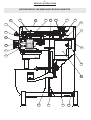
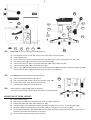
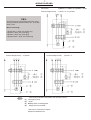
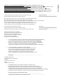
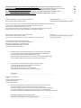
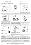
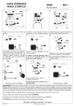
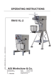
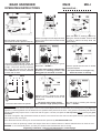
BEAR VARIMIXER
RN20
OPERATING INSTRUCTIONS
2
1
MK-I
MACHINE NO.:
3
Varimixer
I
0
Place the bowl in the bowl arms.
Ensure that the bowl is placed correctly.
Raise the bowl to working position by
Place the mixing tool in the bayonet shaft. pulling the handle forward. Ensure that
The pin of the tool must be turned into the the bowl is placed correctly while the
bowl is lifted.
bayonet hole.
4
5
Varimixer
6
Varimixer
BEAR
BEAR
I
I
0
0
If the mixer is equipped with a timer, set
the time required, by turning the timer to
the right. The mixer will stop automatically, when the time runs out. Set the
timer on HOLD when not used; otherwise
the mixer will not start.
Start the mixer by pressing the green
Push the speed selector lever to obtain
start button > START <
the required speed.
The mixer must only be started when
The speed must be changed only
the bowl is in working position, and
when the mixer is running.
safety guard, if mounted, is closed.
7
8
MIN
1 2
3
MAX
4 5
9
Varimixer
BEAR
I
0
Before the mixer is stopped, the speed
selector lever should be moved to the
lowest speed.
Recommended maximum speeds.
The mixer must not be started
when loaded in high speed position.
Stop the mixer by pressing the red stop
button > STOP <
OVERLOADING: Take care not to overload the mixer. Tough and heavy doughs might reduce the working capacity of the mixer by 75%. The
capacity will be further reduced if the speed of the tool is increased beyond what is recommended, or if a wrong tool is used. Big lumps
of grease or cooled ingredients must be divided into fine particles before placed into the bowl. A long period of overloading will make the
thermal overload relay stop the mixer. Let the mixer rest for approx. 3 minutes, and press the red stop button before pressing the green
start button.
If the mixer is stopped in high speed when loaded, the bowl is to be removed from the mixer and the speed set to low speed before the
bowl is placed in the mixer again.
To the attachment drive should only be connected attachments produced by A/S WODSCHOW & CO.
The mixer is meant for producing masses and doughs which will not release reactions or liberate material which can harm the user.
WARNING: It can cause bodily harm if you stick your hands into the bowl while the mixer is running.
Regarding installation, cleaning and maintenance, se back page.
072003 (012010)
ORDER NO.: 00011 Original manual
GB
2
SERVICE INSTRUCTIONS
BEFORE REPAIR, THE MIXER MUST BE DISCONNECTED.
6
10
7
22
1
41
9
40
16
8
2
55
3
21
43
4
5
44
42
17
18
20
19
3
(1)
Remove the top cover of the mixer (1) and the plastic cover (43) by removing the 2 screws (2).
(3)
The attachment engagement hub is taken out by removing the plastic cover (4), and the 4 bolts (5).
(6)
The control box is taken off by removing the 2 screws (55).
(7)
The special V-belt is exchanged in the following way:
a)
b)
c)
d)
e)
(9)
Remove the top cover of the mixer (1) and the plastic cover (43).
Press the speed selector lever (8) back towards the back of the mixer so that the special V-belt is loosened,
and take off the special V-belt.
The special V-belt is mounted by first placing it on the rear pulley set (9) (the motor pulley set) and open the
pulleys by pulling the special V-belt.
Turn the speed selector lever (8) back towards the back of the mixer (high speed) and mount the special
V-belt on the front pulley set (10).
Adjust the speed, see page 5.
The motor pulley set is taken off in the following way:
a)
b)
Remove the top cover of the mixer (1), the plastic cover (43) and the special V-belt (7).
The motor pulley set can now be taken off by loosening the 2 screws (40).
The upper half of the pulley set can be taken off by removing the circlip (41).
(17)
The legs of the mixer are taken off by removing the screws (18).
(19)
The bottom plate is taken off by removing the legs of the mixer (17)
and the 2 nuts (20).
(21)
18
Relay and thermal overload relay are taken out in the following way:
a)
b)
Remove the top cover of the mixer (1), the plastic cover (43), the special V-belt (7), and the control box (6).
Loosen the screws (22) and take out the relay fittings. The relay can be clicked off the rail and exchanged.
Before relay and thermal overload relay are taken out, the mixer must for safety reasons be disconnected on the main switch, or the connecting cable disconnected.
22
The indicator (23) on the side of the
thermal overload relay, is adjusted to
the rated current of the motor + 10%.
23
(42)
The motor is taken out in the following way:
a)
b)
c)
d)
e)
f)
The voltage to the mixer is switched off or the connecting cable disconnected.
Remove the top cover of the mixer (1), the plastic cover (43), the special V-belt (7), and the motor pulley set (9).
The motor cable is removed from the connecting box (44) of the motor.
Put down the mixer on its back.
Take off the legs of the mixer (17) and the bottom plate (19).
By removing the 4 bolts (16) the motor can be pulled out backwards.
4
11
6
31
30
32
15
12
38
7
34
1
33
8
35
37
36
3
26
25
28
27
29
24
(24)
The planetary head is taken off in the following way:
a)
The top cover of the mixer (1), the attachment engagement hub (3), the special V-belt (7), and the control
box (6) are removed.
b)
The plastic ring (26) can be taken off by knocking it gently on the front edge, and then press a screwdriver in
between the plastic ring and the metal plate at the top of the plastic ring.
c)
Take off the rubber ring (27).
d)
The stainless headcap (28) can now be taken off by knocking it gently on the front edge with a plastic hammer, turn the planetary head 180o, and knock again gently on the front edge.
e)
If only the lower part of the planetary head is to be repaired, the planetary head can be separated by removing the 3 bolts (29).
f)
Take off the grease nipple and washer (30), and pull off the upper half of the pulley set (31) with an extractor.
g)
Take off the movable part (32) of the pulley set.
h)
Take off the 4 screws (33).
i)
The spring (34) is taken off in the following way: The nuts (11) and (12) are removed. The lower fork (15),
the toothed rack (35) and the spring (34) will come up too when the nut (12) is removed. If the toothed rack
(35) is to be exchanged, this can be done now when the lower fork (15) is free. Take out the bolt (38), and
the toothed rack can be exchanged.
j)
The counter nut and the pointed screw (36) are removed, whereafter the speed selector lever (8) can be taken out.
k)
Take off the pin bolt (37) by loosening the counter nut.
l)
By loosening and taking out the 4 bolts (25), the planetary head can be lowered.
5
C
9
B
See drawing A.
16
8
39
32
35
15
34
7
11
Mounting of the planetary head should be done in reverse order.
12
When the lower fork (15) and the spring (34) are mounted, the speed
selector lever (8) is turned counter clockwise, so that it points horizontally
backwards, at the same time as the lower fork is pressed gently down.
When the speed selector lever (8) is now turned clockwise, it will catch
the toothed rack (35) and pull down the lower fork.
Screw on the
nuts (11) and (12).
Drawing A.
38
Be aware that the pin (39) on the lower part (32) of the pulley set is to be
placed as shown in the above mentioned drawing.
When everything has been mounted, the speed has to be adjusted.
14
13
15
ADJUSTMENT OF SPEED:
a)
Control and if necessary adjust the distance (B) = 318 +/- 3 mm, by loosening the 4 bolts (16) and move the motor
backwards and forwards. The tolerance of the distance (B) can be used in cases when there are problems in adjusting the speed correctly, as the distance (B) is dependent on the tolerance of the special V-belt.
b)
The counter nut (11) and the adjusting nut (12) are loosened.
c)
Start the mixer and adjust the lowest speed so that the special V-belt (7) is approx. 1-2 mm (C) from the pulley
edge.
d)
Stop the mixer and tighten loosely the adjusting nut (12), and thereafter the counter nut (11).
e)
The counter nut (13) and the adjusting screw (14) are loosened.
f)
Start the mixer and adjust the highest speed so that the special V-belt (7) is approx. 1-2 mm (C) from the pulley
edge of the motor pulley set (9).
g)
Stop the mixer and tighten loosely the adjusting screw (14), and thereafter the counter nut (13).
h)
Start the mixer and control the measure (C) on both pulley sets at high and low speed, resp.
i)
Be aware that the pin (39) on the lower part (32) of the pulley set is to be placed as shown on the drawing opposite.
Tolerances in the transmission can cause that the special V-belt (7) is hitting the pins of
the pulley sets when the speed has been adjusted. In these cases the distance (B) is to
be reduced and the speed to be adjusted again.
6
50
52
50
51
53
54
48
45
17
47
56
D
46
49
18
20
19
45
(45)
Bowl arms are to be exchanged in the following way:
a)
b)
c)
d)
e)
f)
g)
(50)
The lifting lever is exchanged in the following way:
a)
g)
h)
i)
(58)
Disconnect the mixer on the main switch or disconnect the connecting cable.
Lower the bowl arms.
Put the mixer down on its back and take off the legs of the mixer (17) by removing the screws (18).
The bottom plate (19) is taken off by removing the nuts (20).
Take out the cutter pin (51) securing the lifting bolt (46) and the lifting nut (47).
Take out the lifting bolt (46) and the lifting nut (47).
The 2 circlips (48) are removed from the 2 bowl arm guide rods (49) whereafter the bowl arm guide rods (49)
can be knocked back so that the bowl arms are free and can be taken out.
Start as described above from a) to f) incl.
The crank shaft (52) is taken off by removing the circlip (56).
Ensure that the key (53) has been removed, too.
The lifting lever (50) can now be taken out.
58
45
Safety switch for bowl lift (58) must be adjusted
in a way that it will not be activated when the bowl is in working position.
ADJUSTING OF BOWL HEIGHT:
a)
b)
c)
d)
e)
f)
g)
Lower the bowl arms.
The counter nut (54) is loosened and the cutter pin (51) is taken out.
Take out the lifting bolt (46) with the lifting nut (47).
The bowl height is now adjusted by turning the lifting nut (47) either out or in, on the lifting bolt (46).
Mount the lifting bolt with the lifting nut and the cutter pin, and tighten the counter nut (54).
Ensure that the measure (D) = 127,5 mm is correct when the bowl is raised to normal working position, and
repeat the procedure if the measure is not correct.
Ensure that all mixing tools are fitting in the bowl.
7
WIRING DIAGRAMS:
Connection:
1 phase + 0 + earth, or 2 phases + earth.
Control voltage to relay:
1 phase + 0, or 2 phases.
OBS:
The mixer is to be connected to power via a plug.
The plug must be dimensioned for min. 16 A, 230/
400V~, IP44
When connecting;
1 phase with 0 + earth, use 3 pole plug
2 phases + earth, use 3 pole plug
3 phases + earth, use 4 pole plug
3 phases with 0 + earth, use 5 pole plug
Connection:
3 phases + earth.
Connection:
3 phases+ 0 + earth.
Control voltage to relay:
2 phases.
Control voltage to relay:
1 phase + 0.
(1)
(2)
(3)
(5)
Fuse is only mounted if requested in the receiving country.
* Emergency stop.
* Timer.
# Safety switch for safetyguard.
Safety switch for bowl lift.
* Will only be mounted on request.
# Optional outside the EU.
8
INSTALLATION - CLEANING - MAINTENANCE
INSTALLATION:
The mixer can be placed direct on the floor. Foundation bolts in the floor are only necessary under special conditions, e.g. in
ships. If the 20 L mixer is placed on a bench stand, it must be fastened with the enclosed bolts, see page 2. If the floor is not
level, the position of the mixer can be corrected by loosening the screws (18) placed at the bottom of the outer left side of the
mixer, whereafter the legs can be turned, see page 6. When the mixer is placed correctly, the screws are tightened again.
Ensure that the voltage, phase and hertz printed on the identification plate of the mixer are correct compared with that of the
place of installation. The identification plate is located at the top of the right side of the mixer. Be sure the mixer is properly
connected to the incoming power supply and that the ground or earth connection is made. If the mixer is provided with a five core
cable, the mixer must also be connected to 0 (N). The arrow on the front of the planetary head (see picture 2 page 1), is showing
the direction of rotation of the planetary head. On 3-phase motors the direction of rotation can be changed by interchanging 2
phases of the connecting cable or of the motor. Electric connections must be made in accordance to local regulations.
NOISE LEVEL:
The constant noise level of the workplace of the operator is 72 db (A)
CLEANING:
The mixer should be cleaned daily or after use. Wash by means of a soft brush and pure water. Synthetic detergents should be
used with care, as they destroy the lubricants of the mixer. Washing with a hose is not recommended. Bowls and mixing tools
should be washed in detergents which do not attack aluminium. The suppliers of detergents will be able to recommend the right
type.
LUBRICATION AND MAINTENANCE:
When the mixer is used regularly the varispeed system must be lubricated
approx. once per month. When the mixer is intensively used, or often used
without changes in the speed, the lubrication intervals should be more often.
DIRECTIONS FOR LUBRICATIONS:
Start the mixer and increase the speed up to approx. 50%. Stop the mixer
and take off the top cover of the mixer by removing the 2 screws (2), see
page 2-3.
On top of the shafts of the pulley sets there is a grease nipple, one on each
pulley set. Press the grease through the grease nipples until the grease gun
feels hard, or until grease is pressed out between the shaft and the pulleys.
Put the top cover back, and remember to put in the 2 screws securing
the cover.
Before starting the mixer, the lid must be mounted.
Start the mixer, and set the speed back to low speed.
Stop the mixer and fill up the grease gun with new grease to be ready for the
next lubrication.
TYPES OF GREASE:
Grease for the shafts of the pulley sets: CASTROL LMX.
When repairing the planetary head which is greased for life, the grease CASTROL Molub Alloy 936SF Heavy should be used
in gear wheel and gear wheel rim. The needle bearings of the planetary head must not be greased with this type of grease.
Grease for gear for attachment drive, if any: ESSO Fibrax EP 370
Only this type of grease can be used, and it must not be mixed with other types of grease.
A/S WODSCHOW & CO.
Industrisvinget 6.
DK-2605 Brøndby
Denmark
Phone:
43 44 22 88
Telefax: 43 43 12 80
www.wodschow.dk
Indhold af CE Overensstemmelseserklæring, (Maskindirektivet, 2006/42/EC, Bilag II, del A) Contents of the EC Declaration of conformity for machinery, (Machinery Directive 2006/42/EC, Annex II., sub. A) Inhalt der EG‐Konformitätserklärung für Maschinen, (Richtlinie 2006/42/EG, Anhang II, sub A) Contenu de la Déclaration CE de conformité d’une machine, (Directive Machine 2006/42/CE, Annexe II.A) Inhoud van de EG‐verklaring van overeenstemming voor machines, (Richtlijn 2006/42/EC, Bijlage II, onder A) Contenido de la declaración "CE" de conformidad sobre máquinas, (Directiva 2006/42/EC, Anexo II, sub A) F abrikant; Manufac
turer; Hersteller; Fabricant; Fabrikant; Fabricante: A/S Wodschow & Co. ………………………………………………………………….…… Adresse; Address; A
dresse; Adresse; Adres; Dirección: Industrisvinget 6, DK‐2605 Brøndby, Denmark ………………………………………………………………………. Navn og adresse på den person, som er bemyndiget til at udarbejde teknisk dossier: Name and address of the person authorised to compile the technical file Name und Anschrift der Person, die bevollmächtigt ist, die technischen Unterlagen zusammenzustellen Nom et adresse de la personne autorisée à constituer le dossier technique naam en adres van degene die gemachtigd is het technisch dossier samen te stellen nombre y dirección de la persona facultada para elaborar el expediente técnico Navn; Name; Name
; Nom; Naam; Nombre: Kim Jensen ………………………………………………………………………. Adresse; Address; A
dresse; Adresse; Adres; Dirección: Industrisvinget 6, DK‐2605 Brøndby, Denmark ......................................................................... Sted, dato; Place, date; Ort, Datum; Lieu, date ; Plaats, datum ; Place, Fecha: Brøndby, 15‐12‐2009 ........................................................................ Erklærer hermed at denne røremaskine Herewith we declare that this planetary mixer Erklärt hiermit, dass diese Rührmaschine Déclare que le batteur‐mélangeur ci‐dessous Verklaart hiermede dat Menger Declaramos que el producto batidora • er i overensstemmelse med relevante bestemmelser i Maskindirektivet (Direktiv 2006/42/EC) is in conformity with the relevant provisions of the Machinery Directive (2006/42/EC) konform ist mit den Bestimmungen der EG‐Maschinenrichtlinie (Direktiv 2006/42/EG) Satisfait à l’ensemble des dispositions pertinentes de la Directive Machines (2006/42/CE) voldoet aan de bepalingen van de Machinerichtlijn (Richtlijn 2006/42/EC) corresponde a las exigencias básicas de la Directiva sobre Máquinas (Directiva 2006/42/EC) • er i overensstemmelse med følgende andre CE‐direktiver is in conformity with the provisions of the following other EC‐Directives konform ist mit den Bestimmungen folgender weiterer EG‐Richtlinien Est conforme aux dispositions des Directives Européennes suivantes voldoet aan de bepalingen van de volgende andere EG‐richtlijnen está en conformidad con las exigencias de las siguientes directivas de la CE 2004/108/EC ……………………………………………………………………………………………………………………………………... Endvidere erklæres det And furthermore, we declare that Und dass Et déclare par ailleurs que En dat Además declaramos que •
at de følgende (dele af) harmoniserede standarder, er blevet anvendt the following (parts/clauses of) European harmonised standards have been used folgende harmonisierte Normen (oder Teile/Klauseln hieraus) zur Anwendung gelangten Les (parties/articles des) normes européennes harmonisées suivantes ont été utilisées de volgende (onderdelen/bepalingen van) geharmoniseerde normen/nationale normen zijn toegepast las siguientes normas armonizadas y normas nacionales (o partes de ellas) fueron aplicadas EN454:2000 ; EN60204‐1:2006; EN12100‐1:2005 ……………………………………………………………………………………………………………………………………... EN12100‐2:2005; EN61000‐6‐1:2007; EN61000‐6‐3:2007 ……………………………………………………………………………………………………………………………………... DK GB DE FR NL ES Innehåll i EG‐försäkran om maskinens överensstämmelse, (Maskindirektivet 2006/42/EG, bilaga 2, A) Contenuto della dichiarazione CE di conformità per macchine, (Direttiva 2006/42/CE, Allegato II, parte A) Sisukord EÜ masina vastavusdeklaratsioon , (Masinadirektiiv 2006/42/EÜ, lisa II, punkt A) Treść Deklaracja zgodności WE dla maszyn (Dyrektywa maszynowa 2006/42/WE, Załącznik II, pkt A) Sisältö EY‐vaatimustenmukaisuusvakuutus koneesta (Konedirektiivi 2006/42/EY, Liite II A) T illverkare; Fabbrica
nte; Tootja; Producent; Valmistaja: A/S Wodschow & Co. ………………………………………………………………….…… Osoite: Adress; Indirizzo; Aa
dress; Adres;
Industrisvinget 6, DK‐2605 Brøndby, Denmark ………………………………………………………………………. Namn och adress till den person som är behörig att ställa samman den tekniska dokumentationen: Nome e indirizzo della persona autorizzata a costituire il fascicolo tecnico Tehnilise kausta volitatud koostaja nimi ja aadress Imię i nazwisko oraz adres osoby upoważnionej do przygotowania dokumentacji technicznej Henkilön nimi ja osoite, joka on valtuutettu kokoamaan teknisen tiedoston Namn; Nome e cogn
ome; Nimi; Imię i nazwisko; Nimi: Kim Jensen ………………………………………………………………………. Adress; Indirizzo; Aa
dress; Adres; Osoite: Industrisvinget 6, DK‐2605 Brøndby, Denmark ......................................................................... Ort och datum; Luogo e data; Koht, kuupäev; Miejscowość, data; Paikka, aika: Brøndby, 15‐12‐2009 ........................................................................ Försäkrar härmed att denna blandningsmaskin Con la presente si dichiara che questo mixer planetaria Deklareerime käesolevaga, et Planetaarmikseri Niniejszym oświadczamy, że mikser planetarny vakuuttaa, että tämä mikseri tyyppi • överensstämmer med tillämpliga bestämmelser i maskindirektivet (2006/42/EG) is è conforme alle disposizioni della Direttiva Macchine (Direttiva 2006/42/CE) vastab kehtivatele masinadirektiivi (2006/42/EÜ) nõuetele spełnia wymagania odpowiednich przepisów dyrektywy maszynowej (2006/42/WE) on konedirektiivin (2006/42/EY) asiaankuuluvien säännösten mukainen • överensstämmer med bestämmelser i följande andra EG‐direktiv è conforme alle disposizioni delle seguenti altre direttive CE vastab järgmiste EÜ direktiivide nõuetele spełnia wymagania przepisów innych dyrektyw WE on seuraavien muiden EY‐direktiivien säännösten mukainen 2004/108/EC ……………………………………………………………………………………………………………………………………... Vi försäkrar dessutom att e che Lisaks ülaltoodule deklareerime, et Ponadto oświadczamy, że ja lisäksi vakuuttaa, että • följande (delar/paragrafer av) europeiska harmoniserade standarder har använts sono state applicate le seguenti (parti/clausole di) norme armonizzate kasutatud on järgmisi Euroopa harmoniseeritud standardeid (või nende osi/nõudeid) zastosowano następujące części/klauzule zharmonizowanych norm europejskich seuraavia eurooppalaisia yhdenmukaistettuja standardeja (tai niiden osia/kohtia) on sovellettu EN454:2000 ; EN60204‐1:2006; EN12100‐1:2005 ……………………………………………………………………………………………………………………………………... EN12100‐2:2005; EN61000‐6‐1:2007; EN61000‐6‐3:2007 ……………………………………………………………………………………………………………………………………... SE IT EE PL FI 20
A/S WODSCHOW & CO.
Industrisvinget 6
DK-2605 Brøndby
Denmark
Phone: 43 44 22 88
Telefax: 43 43 12 80
[email protected]
www.bearvarimixer.com