1
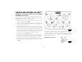
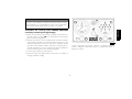
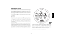
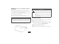
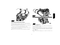
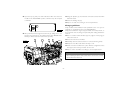
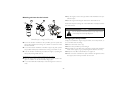
copertina vector marine 28-11-2006 17:42 Pagina 1 C M Y CM MY CY CMY K USE AND MAINTENANCE USO E MANUTENZIONE UTILISATION ET ENTRETIEN BETRIEB UND WARTUNG USO Y MANTENIMIENTO VECTOR MARINE ENGINES Publication edited by Marketing - Adv. & Promotion Print L31900014 - 03/06 Colori compositi SERIES VECTOR SERIES We would like to thank you for buying an IVECO MOTORS product, and compliment you on your choice of engine. Before you carry out any operation involving the engine or its fittings, please read the contents of this manual carefully; compliance with the instructions provided in the manual is the best way to guarantee trouble-free, long term operation of the engine. V08 ENT M75 V08 ENT M11 V08 ENT M12 V12 ENT M11 V12 ENT M18 The contents of this manual refer to the standard configuration of the engine, and the illustrations are purely indicative. Some instructions are provided by giving the sequence of operations to be carried out in order to allow the engine and/or its fittings to perform in a certain way. In some cases they will be dependent on the configuration of the commands and the set-up of the vessel on which the engine is installed; for any points that differ from the contents of this manual, please consult the instructions provided by the Boatbuilder or a specific manual. The information provided below was current at the date of publication. The Manufacturer reserves the right to make modifications at any time without prior notice, for technical or commercial reasons or to update the engines to comply with legal requirements in the various Countries. The Manufacturer declines all liability for any errors or omissions. USE AND MAINTENANCE Please remember that the IVECO MOTORS Technical Service Network is available to offer you its experience and professional skills, wherever you may be. 1 ENGLISH INTRODUCTION CONTENTS Page GENERAL INFORMATION . . . . . . . . . . . . . . . . . . . . . . . . . . . . . .3 Guarantee . . . . . . . . . . . . . . . . . . . . . . . . . . . . . . . . . . . . . . . . . . . . . .3 Spare Parts . . . . . . . . . . . . . . . . . . . . . . . . . . . . . . . . . . . . . . . . . . . . .3 Liability . . . . . . . . . . . . . . . . . . . . . . . . . . . . . . . . . . . . . . . . . . . . . . . . .3 Safety . . . . . . . . . . . . . . . . . . . . . . . . . . . . . . . . . . . . . . . . . . . . . . . . . .3 Engine technical data V08 ENT M75 / M11 / M12. . . . . . . . . . . . .4 Engine technical data V12 ENT M11 / M18 . . . . . . . . . . . . . . . . . .6 Signs . . . . . . . . . . . . . . . . . . . . . . . . . . . . . . . . . . . . . . . . . . . . . . . . . . .8 USE. . . . . . . . . . . . . . . . . . . . . . . . . . . . . . . . . . . . . . . . . . . . . . . . . . . .9 Preliminary checks. . . . . . . . . . . . . . . . . . . . . . . . . . . . . . . . . . . . . . . .9 Starting and stopping the engine . . . . . . . . . . . . . . . . . . . . . . . . . . . .9 Starting and stopping the engine from the analogue control panel . . . . . . . . . . . . . . . . . . . . . . . . . . . . . . . . . . . . .10 Recognising alarms . . . . . . . . . . . . . . . . . . . . . . . . . . . . . . . . . . . . . .13 Managing the engine from the Relay box . . . . . . . . . . . . . . . . . . .14 Proper use of the engine . . . . . . . . . . . . . . . . . . . . . . . . . . . . . . . . .15 Special warnings . . . . . . . . . . . . . . . . . . . . . . . . . . . . . . . . . . . . . . . .16 Running in . . . . . . . . . . . . . . . . . . . . . . . . . . . . . . . . . . . . . . . . . . . . .17 Refuelling . . . . . . . . . . . . . . . . . . . . . . . . . . . . . . . . . . . . . . . . . . . . . .18 CONTROLS AND MAINTENANCE . . . . . . . . . . . . . . . . . . . . .19 Maintenance personnel . . . . . . . . . . . . . . . . . . . . . . . . . . . . . . . . . .19 Accident prevention . . . . . . . . . . . . . . . . . . . . . . . . . . . . . . . . . . . . .19 Frequency . . . . . . . . . . . . . . . . . . . . . . . . . . . . . . . . . . . . . . . . . . . . .20 Requirements . . . . . . . . . . . . . . . . . . . . . . . . . . . . . . . . . . . . . . . . . .22 How to proceed. . . . . . . . . . . . . . . . . . . . . . . . . . . . . . . . . . . . . . . .22 Moving the engine . . . . . . . . . . . . . . . . . . . . . . . . . . . . . . . . . . . . . .31 Disposal of waste . . . . . . . . . . . . . . . . . . . . . . . . . . . . . . . . . . . . . . .31 LONG PERIODS OF INACTIVITY . . . . . . . . . . . . . . . . . . . . . . .32 Preparing the engine for a long period of inactivity . . . . . . . . . . .32 Restarting the engine after a long period of inactivity . . . . . . . . .32 Indications for initial start-up or start-up after a long period of inactivity . . . . . . . . . . . . . . . . . . . . . . . . . . . . . . . . . .33 ENGINE MALFUNCTIONS . . . . . . . . . . . . . . . . . . . . . . . . . . . . .34 Page EMERGENCIES ON BOARD . . . . . . . . . . . . . . . . . . . . . . . . . . . .36 IN APPENDIX . . . . . . . . . . . . . . . . . . . . . . . . . . . . . . . . . . . . . . . . . . . Oil viscosity level according to surrounding temperatures . . . . . . . Control panel operating requirements . . . . . . . . . . . . . . . . . . . . . . 2 GENERAL INFORMATION The following information is intended to encourage caution when using the engine, so as to avoid damage to persons or property as a result of improper or incorrect behaviour. The engines must only be used for the purposes indicated by the Manufacturer. Any tampering, modification and use of non-original spare parts may compromise proper operation of the engine and safe navigation; never, under any circumstances make any modifications to the wiring and to the units equipping the engine, or connect them to other power systems. Pay particular attention to moving parts of the engine, to high temperature components and to circuits containing pressurised fluids; its electrical equipment houses electrical currents and voltage. The exhaust fumes produced by the engine are bad for your health. The engine must only be moved using suitable lifting tackle, making use of the U-bolts provided on the engine for that purpose. The engine must not be started up and used until the installation for which it is designed has satisfied all necessary safety requirements, or has been guaranteed to comply with local laws and regulations. The operations required to guarantee the best possible use and preservation of the engine must only be carried out by persons of proven experience, equipment with tools considered suitable by IVECO MOTORS. For the purpose of safety, further recommendations are given in the chapter CONTROLS AND MAINTENANCE. GUARANTEE In order to ensure that your engine gives the best possible performance and to take advantage of the IVECO MOTORS guarantee, you must follow the indications provided in this publication with great care; failure to do so may result in invalidation of the guarantee. SPARE PARTS Always use Original IVECO MOTORS Spare parts. This is essential to keep the engine in original running order. The use of non-original spare parts will not only invalidate the guarantee, but will mean that IVECO MOTORS will not be considered liable in any way during the whole working life of the engine. LIABILITY The Manufacturer will only be considered liable subject to performance of the control and maintenance operations indicated and described in this manual; to this effect, proof that these operations have been performed must be provided. Any special maintenance operations that may be necessary must be carried out by qualified technicians from authorised Workshops in the IVECO MOTORS Network, using the instruments and equipment provided for the purpose. 3 ENGLISH SAFETY ENGINE TECHNICAL DATA V08 ENT The technical code and serial number are indicated on a plate, which is located on different parts of the engine, according to the model: flywheel casing, tappet cover, coolant tank. Code V08 ENT M75/M11/M12 Engine family FVME Cycle 4-stroke diesel Number and arrangement of cylinders 8, 90° V Bore x stroke 145 x 152 mm 3 Total displacement 20,080 cm Air system Supercharged aftercooled Injection type DirectCommonrail, electronically managed Engine direction of rotation Anticlockwise (seen from flywheel side) Dry weight 1980 kg Electrical system 24 V Accumulator/s capacity discharge current 260 Ah or above 1500 A or above Available settings (*) V08 ENT M12 A1 883 kW (1200 CV) @ 2300 rpm A2 810 kW (1100 CV) @ 2300 rpm Available settings (*) V08 ENT M11 A2 810 kW (1100 CV) @ 2300 rpm B 750 kW (1020 CV) @ 2200 rpm C 635 kW (863 CV) @ 2100 rpm Available settings (*) V08 ENT M75 C 600 kW (816 CV) @ 1800 rpm D 551 kW (750 CV) @ 1800 rpm (*)Net power to the flywheel in compliance with ISO 3046-1. Test conditions: T 25 °C; atmospheric. pressure 100 kPa; relative humidity 30%. WARNING Any alteration of the above mentioned characteristics, in particular modification of the data stored in the injection system electronic units or the characteristics of the engine and its fittings, is strictly prohibited, penalty invalidation of the guarantee and absence of all liability on the part of IVECO MOTORS. 4 ENGLISH 05_102_V 05_101_V Engine: VECTOR V08 ENT M75 / M12 Engine: VECTOR V08 ENT M75 / M12 1. Air filter clogging sensor - 2. Air filter - 3. After-cooler heat exchanger - 4. Exhaust gas discharge - 5. Lifting U-bolt - 6. Common Rail fuel distributor - 7. Thermostat valve location - 8. Lifting U-bolt - 9. Fuel filters switchover - 10. Fuel filters - 11. Coolant level indicator - 12. Sea water drainage - 13. Engine coolant pump - 14. Engine coolant discharge plug - 15. Cooled exhaust manifold - 16. Location of removable anode - 17. Oil vapour filter. 1. Coolant tank pressurisation plug - 2. Oil filters - 3. Lubricant drainage tap - 4. Electric oil discharge pump - 5. Lifting U-bolt - 6. Lubricant filler hole - 7. Oil dipstick - 8. Lifting U-bolt - 9. Exhaust gas discharge - 10. Electronic control unit - 11. Fuel outlet connector to tank - 12. Engine fuel inlet connector - 13. Sea water outlet - 14. Accelerator position sensor - 15. Electrical starter motor - 16. Fuel transfer pump 17. Disposable anode - 18. Sea water pump - 19. Sea water pump intake. 5 ENGINE TECHNICAL DATA V12 ENT The technical code and serial number are indicated on a plate, which is located on different parts of the engine, according to the model: flywheel casing, tappet cover, coolant tank. Code V12 ENT M11/M18 Engine family FVME Cycle 4-stroke diesel Number and arrangement of cylinders 12, 90° V Bore x stroke 145 x 152 mm Total displacement 30,100 cm3 Air system Supercharged aftercooled Injection type DirectCommon rail, electronically managed Engine direction of rotation Anticlockwise (seen from flywheel side) Dry weight 2900 kg Electrical system 24 V Accumulator/s capacity discharge current 330 Ah or above 1800 A or above Available settings (*) V12 ENT M18 A1 1325 kW (1800 CV) @ 2300 rpm A2 1201 kW (1632 CV) @ 2300 rpm B 1152 kW (1565 CV) @ 2200 rpm C 1001 kW (1360 CV) @ 2100 rpm Available settings (*) V12 ENT M11 C 956 kW (1300 CV) @ 1800 rpm D 846 kW (1150 CV) @ 1800 rpm (*)Net power to the flywheel in compliance with ISO 3046-1. Test conditions: T 25 °C; atmospheric. pressure 100 kPa; relative humidity 30%. WARNING Any alteration of the above mentioned characteristics, in particular modification of the data stored in the injection system electronic units or the characteristics of the engine and its fittings, is strictly prohibited, penalty invalidation of the guarantee and absence of all liability on the part of IVECO MOTORS. 6 ENGLISH 05_104_V 05_103_V Engine VECTOR V12 ENT M11 / M18 Engine VECTOR V12 ENT M11 / M18 1. Air filter - 2. Air filter clogging sensor - 3. After-cooler heat exchanger - 4. Exhaust gas discharge - 5. Lifting U-bolt - 6. Air intake deparator/ manifold - 7. Common Rail fuel distributor -8. Thermostat valve location - 9. Lifting U-bolt - 10. Fuel filters switchover - 11. Fuel filters 12. Coolant level indicator - 13. Sea water drainage - 14. Engine coolant discharge plug - 15. Engine coolant pump - 16. Cooled exhaust manifold - 17. Sea water drainage from after-cooler - 18. Location of disposable anode - 19. Oil vapour filter housing. 1. Coolant tank pressurisation plug - 2. Oil filters - 3. Lubricant drainage tap - 4. Electric oil discharge pump - 5. Lifting U-bolt - 6. Lubricant filler hole - 7. Oil dipstick - 8. Lifting U-bolt - 9. Exhaust gas discharge - 10. Electronic Control Unit - 11. Cooled exhaust and turbocharger 12. Fuel outlet manifold to tank - 13. Engine fuel inlet connector - 14. Electric starter motor - 15. Accelerator position sensor - 16. Fuel transfer pump - 17. Disposable anode - 18. Sea water pump - 19. Sea water pump inlet/intake. 7 SIGNS Certain warning signs are affixed to the engine, and their meanings are indicated below. NOTE: The signs with an exclamation mark on them underline a potential danger. Lifting point (engine only). Danger of burning: Expulsion of hot water under pressure. Fuel Cap (on the fuel tank, if there is one). Danger of burning: Presence of high temperature parts. Oil Cap. Danger of fire: Fuel present. Danger of impact or catching on moving parts: Presence of fans, pulleys, belts or the like. Oil dipstick. 8 USE WARNING PRELIMINARY CHECKS For engines fitted with an electric pre-lubrication system Press the engine electric system power switch to start the pre-lubrication function, for which the relevant indicator light will turn on. Start-up of the engine, as described in the following pages, must only take place after allowing a sufficient amount of time to complete prelubrication, or after the indicator light has gone out. CAUTION! Before starting the engine, make sure that no combustible vapours or gasses are present in the engineroom. STARTING AND STOPPING THE ENGINE For vessels equipped with instrument panels that are not manufactured by IVECO MOTORS A #(!2'% $)3#(!2'% The start-up and shut-down operations described in the following pages apply to an on-board control panel manufactured by IVECO MOTORS; if the vessel is fitted with an instrument panel that has been customised by the Boatbuilder or Fitter, these operations may vary according to the various choices made during construction. In these cases, follow the start-up/shut-down sequence and use the instrument panel description provided by the Boatbuilder on specific documentation. %6 /&& B %6 /. Electronic pre-lubrication module A. - B. Commands not active 9 04_037_C ENGLISH Start-up and shut-down of this engine are managed entirely by the Electronic Control Unit; the start-up phase commences when the relevant buttons or switches are released. Before starting the engine each time: Make sure that the sea-water inlet valve is open. Operation of the sea water pump without water would cause irreparable damage to the internal rotor within a very few seconds. Check the level of technical fluids (fuel, engine oil and coolant). STARTING AND STOPPING THE ENGINE FROM THE ANALOGUE CONTROL PANEL Procedure for start-up from the main IVECO MOTORS control panel 2 5 4 Make sure that the electrical switch indicating ENGINE ROOM BRIDGE on the Relay Box unit (located near the engine room) is in the BRIDGE position, then proceed as follows: 1. Lift the protective cover over the key switch (8), insert the key and turn it to the right to position 8B. 2. Make sure that the analogue instruments are showing values that conform with the relevant physical parameters (temperature, battery voltage and oil pressure). 3. Wait for the beeper to stop sounding and for the alarm indicator lights on the indicator module (5) to switch off, with the exception of the “alternator recharge” and “low oil pressure” indicators. At the same time, check that the indicator test has been performed successfully (information on how to interpret this test and indications on the module are given in the relevant paragraph). 4. Turn the key to position 8C and release it. 5. Once startup has been completed, make sure that the analogue instruments are showing values that conform with the relevant physical parameters (temperature, battery voltage and oil pressure). 6. If the engine does not start, it will only be possible to turn it back to the start position after first returning the switch to the rest position 8A. 3 1 6 7 10 9 8 04_354_N 1. Coolant temperature indicator - 2. Rev counter and hour counter 3. Voltmeter - 4. Beeper - 5. Indicator and alarm module - 6. Engine oil pressure indicator - 7. Control panel instrument light switch - 8. Key switch to start/stop the engine - 9. Button to stop the engine - 10. Button to disable the beeper. Detail of the key switch 8A 8B 8C 04_356_N 10 WARNING 2 1 In order to ensure that the on-board control panels function properly during navigation, it is essential that the engine only be started after testing of the indicator lights and beeper has been completed. 3 1 Enable the secondary control panel, by turning the key switch on the main panel to position 8B (see requirements and procedure given in previous paragraph). 2. Wait for the beeper to stop sounding and for the alarm indicators on the indicator module (5) to switch off, with the exception of the “alternator malfunction” and “low oil pressure” indicators. At the same time, check that the indicator test has been performed successfully (information on how to interpret this test and indications on the module are given in the relevant paragraph). 3. Press the green button (5) and release it. 4. When the engine has started, make sure that the rev indicator is showing a plausible reading. ENGLISH Procedure for start-up from IVECO MOTORS secondary control panel (fly-bridge) 4 5 6 04_355_N 1. Rev counter and hour counter - 2. Beeper - 3. Indicator and alarm module - 4. Button to disable the beeper - 5. Engine start button - 6. Engine stop button. 11 Stopping the engine It is recommended that you run the engine for a few minutes at minimum speed and with no load before stopping it; this will allow the temperature to drop evenly and will avoid harmful thermal shocks. A. The engine is stopped from the main IVECO MOTORS control panel by turning the key switch to the rest position 8A. B. The IVECO MOTORS secondary control panel is stopped by pressing the red button (6) on the control panel. The layout of this engine foresees the presence, either in or near the engine room, of a button that can be pressed to stop the engine in an emergency, using “excited” logic (as required or prescribed by the certification Bodies). To re-start the engine from the main control panel: 1. Return the key switch to the rest position 8A to reset all the onboard control panel functions. 2. Proceed as described previously. To re-start the engine from the secondary control panel: 1. Make sure that the panel has been enabled (key switch on the main control panel turned to position 8B). 2. Press the green button (5) and release it; when the engine has started, make sure that the rev indicator is showing a plausible reading. 12 RECOGNISING ALARMS IVECO MOTORS on-board control panels with analogue instruments are fitted with an electronic module that includes the indicator lights and the interface, timer and alarm storage circuits. The figure illustrates the dial and the key indicates the meaning of the alarm signals sent by all the indicator lights; some types of engine and relevant equipment only make some of the above mentioned functions available . If the Boatyard uses different technical options there may be changes to the above. 7 4 6 3 8 13 9 10 ENGLISH 5 11 Operation 2 When the key switch is turned to position 8B the signals and alarms module will perform an efficiency test on all the indicator lights, lasting 5 seconds, with the exception of the “Pre-lubrication”, “Pre-post heating”, “EDG system malfunction” indicators, and simultaneously the beeper sounds. It is possible to stop the beeper before the end of the test, by pressing the relevant button. During start-up and for the following 15 seconds, all alarm functions are disabled; after this period, each alarm detected by the sensors provided on the engine will result in the relevant indicator flashing and a simultaneous warning sound from the beeper. If the beeper is disabled by pressing the relevant button, the indicator light will turn on without flashing and the alarm will be stored until the engine is next stopped. 1 12 04_234_N 1. Maximum allowed rotation speed exceeded (on request) - 2. Water in the fuel pre-filter - 3. Engine coolant level low - 4. Alternator malfunction - *5. Oil filter blocked - * 6. Oil vapour filter blocked - *7. Prelubrication in progress - 8. Air filter blocked - * 9. Fuel filter blocked 10. Coolant temperature high - 11. Oil pressure low - *12. Pre-post heating - 13. Malfunction in EDC electronic injection system. *Alarm functions not available with standard setup. 13 MANAGING THE ENGINE FROM THE RELAY BOX The box contains the components that protect the electrical lines from accidental short-circuits or excessive current absorption. These components do not require replacing, as the electrical continuity of the circuit will be restored automatically as soon as the malfunction ceases. By means of the electronic unit indicated as the "Relay Box", installed close to the engine room so that it can be accessed during maintenance operations and during navigation, it is possible to start and stop the engine and manage its running speed, while at the same time preventing accidental start-up from the bridge. The relay box contains the multi-pin connector (6), protected by a screw-on cover, used to connect to the IVECO MOTORS diagnosis instruments. CAUTION! Never switch the ENGINE ROOM / BRIDGE selector when the engine is turning. Start-up procedure 9 8 1. Turn the switch 1 in the Relay box to the "ENGINE ROOM" position. This totally excludes the bridge commands and must never be carried out when the engine is turning. 2. Turn the switch 2 to the “IGNITION” position to power the system's electric circuits and enable the commands on the panel. 3. Press and release the START button (3), to commence the startup phase. 7 &+(&. (1*,1( 5220 530 %5,'*( ,*1,7,21 67$57 530 05_007_V 1 2 3 4 5 6 WARNING 1. Selector for control from bridge or engine room - 2. Engine electric circuits power supply switch - 3. Button to start from the engine room - 4. Maintenance alarm" reset button - 5. Button managing acceleration and deceleration - 6. Connector for diagnosis instrument - 7. EDC blink code indicator - 8. Maintenance interval expired indicator - 9. Bad engine parameters indicator (WARNING). Start-up of the engine is managed entirely by the Electronic Control Unit; the start-up phase commences when the START button is released. 14 Indicator (Maintenance interval expired) The acceleration/deceleration function (RPM+ / RPM-) is only active when switch 1 is in the "ENGINE ROOM" position and switch 2 is in the “IGNITION” position. Acceleration (RPM+) Press button 4 in position RPM +, for a progressive increase in engine speed; this increase stops when the button is released, and the speed reached will be maintained until the next operation is carried out. Deceleration (RPM -) Press command 4 in position RPM - for a progressive decrease in engine speed; this reduction will stop when the button is released, and the speed reached will be maintained until the next operation is carried out. All settings are cancelled when the engine is stopped. When the orange indicator light 8 (figure on page 14) turns on, this indicates that it is necessary to carry out level 1 maintenance operations. When the operations have been completed, press button 4 (figure on page 14) to reset the counter and start a new countdown cycle. NOTE: The effect of commands “RPM +" and "RPM -" varies according to the length of time the command is given: A. during the first 3 seconds the increase in speed is restricted B. After the first 3 seconds the increase is faster and enables maximum running speed to be reached in approximately 20 seconds. Indicates the results of engine working parameter monitoring operations. Further details are provided in the section on ENGINE MALFUNCTIONS. NOTE: The indicator is only present on the relay box. CHECK indicator Indicates the state of efficiency of the electronic engine control system. Further details are provided in the section on ENGINE MALFUNCTIONS. Indicator Stopping procedure 1. Return the “IGNITION” switch (2) to its original position. 2. Return switch 1 to the "BRIDGE" position to disable use of the commands on the Box and enable start-up using the bridge commands. 15 (Warning) ENGLISH Running speed management FOR PROPER USE OF THE ENGINE SPECIAL WARNINGS Coolant temperature high Do not continue to press the starter, when the engine has started. Do not remain in dock while waiting for the engine to warm up, but after starting, commence navigation at low speed; the working temperature will be reached properly with the engine running at medium speeds. Do not operate the engine at minimum speed for long periods, as this encourages the production of harmful exhaust and does not guarantee optimum performance. The engine speed must be increased and decreased gradually, to allow regular combustion and proper operation of all engine components. The maximum cruising speed must not be more than 90% of the speed corresponding to Maximum power (see section on ENGINE TECHNICAL DATA). During navigation, check that: • The engine coolant temperature does not reach the alarm threshold. • The oil pressure remains within normal values. If the temperature indicated on the instrument is considered too high, or if the alarm is displayed, reduce speed and return to port to check the state of the sea water intake and cooling system circuits; also check and have checked: • tension of the water pump and alternator command belts. • operation of the thermostat valve. • whether or not the heat exchangers are clean. CAUTION! When the engine is warm, a pressure liable to cause hot liquid to be expelled with extreme violence is created within the cooling circuits. This results in a danger of burning. Only open the coolant tank cap if strictly necessary, and only when the engine is cold. Low lubricant pressure If the pressure indicated by the instrument is considered insufficient, or if the “low oil pressure” indicator lights up, stop the engine and check the oil level. Top up if necessary (see CONTROL AND MAINTENANCE section). If the condition persists, return to port at low speed and contact an Authorised Service Centre. 16 Water in the fuel pre-filter Battery recharge or alternator malfunction It is a good rule to drain the water from the filters, before the relevant indicator comes on. Avoid using the engine with the fuel tank only a small reserve of fuel; this encourages the formation of condensation and makes it more likely you will suck up dirt or air, resulting in engine stoppage. Check it or have it checked periodically for cleanliness, wear and proper tensioning of the drive belt. The drive members are located under protective casings. These must only be removed when the engine is not turning. CAUTION! When refuelling, always pay great care to ensure that no solid or liquid pollutants enter the fuel tank; you must also remember that smoking and live flames are prohibited when refuelling. Irregularities in the electrical system Periodically check, particularly during the winter, to ensure that the batteries are clean and in full working order, checking and topping up as indicated in the section CONTROLS AND MAINTENANCE; always comply with the warning notices provided. Should it be necessary to replace the batteries, always comply with the characteristics indicated in the section TECHNICAL DATA. Air filter blocked and exhaust circuit inefficient Inspect the cleanliness of the air intakes and discharge pipes on a regular basis. The maintenance intervals indicated in this manual only take into account the performance of engine components, and not any additional fittings installed by the Boatbuilder and any external events. WARNING If a voltage of less than 11 V (for 12 V rated systems) or 22 V (for 24 V rated systems) is shown, contact specialised technical staff and have them diagnose the efficiency of the batteries and the recharging system. CAUTION! Visually check that the exhaust circuit is not blocked or damaged, so as to prevent dangerous fumes within the vessel. RUNNING IN Thanks to modern engine construction technology, no particular running in procedure is required. However, it is recommended that, for the first 50 hours, you do not use the engine at high power for long periods. 17 ENGLISH CAUTION! REFUELLING Parts to be supplied Cooling circuit (1) Lubrication circuit (2) total capacity (3) Periodic changing: oil sump at minimum level oil sump at maximum level Fuel tank (4) (4)Only use normal commercial diesel fuel (EN 590 standards). Do not use additives. Do not use fuels derived from the synthesis of organic substances and vegetable oils (Biodiesel). V08 ENT litres (kg) V12 ENT litres (kg) 70 110* WARNING 50 (45.5) 72* (65) 20 (18.2) 40 (36.4) 46* (42) 61* (55) Refuelling from drums or tanks may result in pollution of the diesel fuel, with the risk of damage to the injection system; if necessary, filter the fuel in a suitable manner or allow sedimentation of the impurities before refuelling. - - Low temperature diesel EN590 specifications distinguish different classes of diesel fuel, identifying the characteristics of those best suited to low temperatures. It is entirely up to the Oil companies to comply with these regulations, which foresee that fuels suited to the climactic and geographic conditions of the various Countries be distributed. * Temporary data. (1)Use a mixture of water and 50% PARAFLU 11 even during the summer months. As an alternative to PARAFLU 11, you can use another product that complies with international specifications SAE J 1034. (2)Use lubricants that comply with international specifications ACEA E3-96 or alternatively E2-96, API CF - CH4 (associated with fuels with a percentage sulphur < 0.5%), MIL - L - 2104 F. Viscosity level SAE 15W40. The viscosity level of oil to be used depending on surrounding temperatures is given in the table provided in the appendix. Oil consumption is considered acceptable when it reaches a maximum of 0.5% of fuel consumption. (3)The amounts indicated refer to initial refuelling, and include filling the engine, sump and filter. Filling up with marine gear oil For the amount and types of oil to be used in the marine gear, please see the manual provided by the Manufacturer. 18 • replacing or topping up lubricant (hot engine oil may cause burns and scalds. Only carry out these operations when the oil has dropped to a temperature of below 50°C). When working in the engine compartment, pay particular attention to how you move, to avoid contact with moving parts or high temperature components. Wear goggles and use high pressure air jets (maximum air pressure used to clean is 200 kPa (2 bar, 30 psi, 2 kg/cm2). Wear a protective helmet when working in an area were there are suspended loads or systems installed at head-height. Use protective hand cremes. Immediately replace wet overalls. Always keep the engine clean, removing oil, grease and coolant stains. Store cloths in flame-proof containers. Do not leave foreign bodies on the engine. Use suitable, safe containers for used oil. When completing a repair, make suitable provisions to stop the engine taking in air if, after start-up, an uncontrolled increase in engine speed were to occur. MAINTENANCE PERSONNEL The engine control and maintenance operations described in the following chapter require training, experience and compliance with current safety regulations; for this reason they must be carried out by special technicians, as indicated below. Controls: by workshop technicians or the vessel user if necessary. Periodic or level 1 maintenance: by qualified personnel using suitable equipment and adequate means of protection. Operations marked by the key symbol. Special or level 2 maintenance: by qualified personnel from Authorised Service Centres who have detailed technical information and specific equipment. Operations marked by the key symbol. The Authorised Service Centres are the ones in the IVECO MOTORS Technical Service Network. ACCIDENT PREVENTION Always wear heavy-duty footwear and overalls. Never wear loose, flapping garments, rings, bracelets and/or necklaces in the vicinity of engines or moving parts. Always wear protective gloves and goggles when: • filling up batteries with acid solution • refuelling with inhibitors or antifreeze 19 ENGLISH CONTROLS AND MAINTENANCE Planned or Level 1 maintenance Frequency CAUTION! Do not carry out maintenance operations when the electric power supply is turned on: always check to ensure that the appliances are properly earthed. During diagnosis and maintenance operations, make sure that your hands and feet are dry, and whenever possible use insulating stands. Clean air filter/s 300 hours (2) (7) Check corrosion of zinc anodes 300 hours (4) (7) Check state of oil vapour filter (indicator may be present) 300 hours (7) Drain/suck condensation from fuel tank/s 300 hours (1) (7) FREQUENCY Controls Frequency Check oil level in engine 150 hours Check oil level in marine gear 150 hours Check engine coolant level 150 hours Check exhaust pipe/s for damage 150 hours Drain water from the fuel pre-filter 150 hours(1) Check/top up electrolyte level in batteries and clean terminals Half-yearly The maintenance intervals indicated below take into account the typical working factors for various types of engine use; the most suitable interval for maintenance operations for the various applications will be indicated by the maintenance staff, according to the way and working conditions in which the engine is used. 20 Change engine oil 900 hours (5) (7) Change oil filters 900 hours (5) (7) (8) Change fuel filters 900 hours (1) (7) (8) Change the fuel pre-filter 900 hours(1) (7) Change oil in the marine gear see relevant details Inspect sea chest half-yearly Check tension or change belt 1200 hours or 2 years Change coolant 1200 hours or 2 years Change air filter 2 years Change oil vapour filter 2 years (5) Frequency Change electrical injectors 3000 hours Change coolant pump 3000 hours Change sea water pump 3000 hours Adjust play in valves-rocker arms 3000 hours Clean the turbocharger 3000 hours (5) Clean heat exchangers 6) Given the nature of the heat exchangers used, cleaning must only be carried out by IVECO MOTORS Technical Service Network staff. 7) Must be performed annually, even if the required number of working hours are not reached. 8) Only use filters with the following characteristics: - filtration level < 12 μm - filtering efficiency ß > 200. 2 years WARNING (6) When using fuel with a percentage sulphur exceeding 0,5%, or when using oils that do not comply with the specifications provided in the refuelling table, the times at which the engine oil, engine oil filter and oil vapour filter must be halved or adapted to suit the use and working conditions of the engine; for further information, please consult the technicians responsible for maintenance. I) Maximum period when using good quality fuel , (EN 590 standard); this is reduced if the fuel is contaminated and alarms are triggered due to blockage of the filters and presence of water in the pre-filter. When blockage of the filter is indicated, it must be replaced. If the water in pre-filter indicator does not go out after drainage, the prefilter must be replaced. 2) The frequency with which operations are carried out will depend on the working conditions and efficiency/wear of the product. If the engine is not used for long periods of time, check it before you start it. 3) N.C. 4) The anode must be replaced if corrosion has exceeded 50% of the volume of zinc. 5) Replace lubricants according to the frequency indicated in the REFUELLING table. 21 ENGLISH Special or Level 2 maintenance REQUIREMENTS HOW TO PROCEED Checking oil level in engine Do not disconnect the batteries with the engine running. Do not carry out arc welding operations in the vicinity of the engine without first removing electrical cables and electronic units. After each maintenance operation involving disconnection of the batteries, make sure that the terminals have been properly locked onto the poles. Do not use battery chargers to start the engine. Disconnect the on-board network batteries when recharging. Do not paint the appliances, components and electrical connectors equipping the engine. Disconnect the batteries before any electrical operations. Contact the Boatyard before installing electronic equipment on board (two-way radios, echo-sounding equipment, etc.). Only proceed with the engine stopped and at a low temperature, so as to avoid the risk of burning. Using the dipstick, check that the oil level is between the "Min" and "Max" levels. If the level is too low, top up through the inlet on the side of the engine, after first removing the relevant cap. WARNING After topping up, make sure that the oil level does not exceed the "Max" limit marked on the dipstick. Make sure that the dipstick is inserted properly and the filler cap is turned in a clockwise direction until it stops turning completely. Checking oil level in marine gear Check the oil level in the marine gear following the indications provided in the marine gear Manufacturer's manual. Checking coolant level When testing, it is prescribed that the engine be inclined by an amount corresponding to its position during navigation. Make sure that there is a sufficient amount of coolant fluid, by checking that the level indicator (1) is between the "Min" - "Max" signs. 22 Checking exhaust pipe/s for damage 2 1 Visually check that the exhaust system is not blocked or damaged. Make sure that there is no risk of dangerous fumes within the vessel. Contact the Boatyard if necessary. The high risk of refuelling with fuel that is polluted by foreign bodies and water means that it is necessary to perform this control even if no alarm is shown on the on-board control panel. Proceed with the engine stopped. Place a container under the pre-filter to collect the fluid. Unscrew the tap plug (1) in the bottom part of the pre-filter; in some layouts the plug includes a sensor to detect the presence of water in the diesel. Drain off liquid until only “diesel” can be seen. Close the plug again, tightening it by hand until it locks. Dispose of the drained fluids according to current requirements. /+0 05_024_V Should it be necessary to top up the level, only do so with the engine stopped and at a low temperature, so as to avoid the risk of burning, proceeding as follows: Remove the tank presurisation cap (2). Top up the tank using a mixture of 50% clean water (not distilled) and Paraflù 11 (see REFUELLING table), checking the level reached on the indicator (1). Close the filler hole, making sure the cap is screwed all the way down. 1 05_018_V 23 ENGLISH Draining water from the fuel pre-filter /# : Checking the level of electrolyte solution in the batteries CAUTION! Place the batteries on a level surface, then proceed as follows. Visually check that the fluid level is between the "Min" and "Max" limits; in the absence of references, check that the fluid covers the Lead plates inside the elements by approximately 5 mm. If necessary, top up with distilled water only those elements in which the level is below minimum. On this occasion, make sure that the terminals and clamps are clean, properly locked and protected by vaseline. The batteries contain sulphuric acid, which is extremely caustic and corrosive; always wear protective gloves and goggles when topping them up. Whenever possible it is recommended that this control be carried out by specialised personnel. Do not smoke or use live flames near the batteries during controls, and make sure that the room you are working in is adequately ventilated. Cleaning the air filters WARNING Proceed with the engine stopped. Loosen the clamps holding the two filters (1, figure on the next page). Remove the filters from their housing. Blow dehumidified compressed air through the filter element, from the inside outward (maximum pressure 200 kPa), or wash with water only. Do not use detergents; do not use diesel. If the filters are damaged, replace them. Replace the filters at least once every 2 years. Return them to their proper position and lock the retaining clamps. Contact specialised technical staff if all the elements in the battery need topping up with a considerable amount of distilled water, and have them diagnose the efficiency of the batteries and the recharging system. Some types of battery have a single cover for all the inspection plugs. To access the elements, use a lever as shown in the figure. 04_362_N 24 1 05_020_V 05_008_V Checking corrosion of zinc anodes Only proceed with the engine stopped and at a low temperature: Provide suitable containers to ensure that no water is dispersed inside the vessel during removal of the anodes. Remove the anodes (1), unscrewing them from their housings (see location in the section ENGINE TECHNICAL DATA). Make sure that corrosion has not exceeded 50% of the volume of zinc. If this is the case, change them. Replace the anodes in their housings, changing the seal gaskets. 05_008_V 1 Changing engine oil Only proceed with the engine stopped and at a low temperature, so as to avoid the risk of burning. The oil is extracted with the aid of the electric pump, controlled using the button on the relevant electronic module control panel; for safety reasons the operation is only possible with the start/stop key switch in position 8A (stop). Connect the system drainage tap to a container to collect the used oil. 25 ENGLISH 1 Using the dipstick (1), check that the oil level is between the "Min" and "Max" levels. Close the drainage tap (4). Dispose of used oil according to current requirements. Open the tap (4) and press and hold button A on the electronic module in the DISCHARGE position, until the sump has emptied completely. Changing oil filters A #(!2'% Only use filters with a filtration level equivalent to the ones you are replacing (or as indicated in the secion FREQUENCY). Only proceed with the engine stopped and at a low temperature, so as to avoid the risk of burning, and preferably after having drained the used oil. Place a container under the filter support (3, figure on this page) to collect the used oil. Unscrew and remove the filters. Carefully clean the surfaces that are in contact with the gaskets. Damp the new filter seals with a thin layer of oil. Hand screw the new filters into place until the seal gasket touches the support, then lock by a further 3/4 of a turn. Dispose of the used filters according to current requirements. $)3#(!2'% 04_036_C Fill up with fresh oil through the feeder hole (2), taking care to use the types and amounts of oil indicated in the table REFUELLING. When you finish, fasten the feeder hold cap firmly. 05_008_V 4 3 2 1 WARNING When replacing the filters, make certain that no oil comes into contact with the alternator drive belt. 26 Only use filters with a filtration level equivalent to the ones you are replacing (see section FREQUENCY). If you intend to proceed with the engine stopped Only proceed with the engine at a low temperature, so as to avoid the risk of burning. Remove the filters (2/3) by unscrewing them. Damp the new filter seal with gasoline or engine oil. Hand screw the new filters into place until the seal gasket touches the support, then lock by a further 3/4 of a turn. Bleed any residual air as described below. 1 A If you intend to proceed with the engine turning The support with switching lever means that, if necessary, the filters can be replaced even with the engine turning. The instructions given above for replacement are dependent on the lever being turned as described below: Switch the lever (1) to position A and replace filter (2). Switch the lever (1) to position B and replace filter (3). Return the lever (1) to the central position so that you do not restrict the flow of fuel feeding the engine. Bleed any residual air as described below. B 3 2 05_023_V 05_ CAUTION! Proceed with extreme caution, given the high temperature of the fluid and the presence of moving parts. Always wear suitable personal protection equipment. WARNING Do not fill the new filters until they have been fitted on the support, to avoid the risk of any harmful impurities entering the injection system and circuit. 27 ENGLISH Changing fuel filters Stop the engine, remove the pipe and lock the manifold to the prescribed torque. Start the engine following the instructions described above. Bleeding air from the fuel circuit 1 2 3 Ensure that any fuel coming out of the manifolds is not dispersed into the environment. CAUTION! Do not attempt to bleed the system in any way, as this is unnecessary and extremely dangerous. 05_016_V 1. Bleeder pipe on prefilter - 2. Bleeder pipe on filter support 3. Bleeder pipe on high pressure pump. Changing the fuel pre-filter Only proceed with the engine stopped and at a low temperature, so as to avoid the risk of burning. Remove the water sensor (3). Remove the pre-filter by unscrewing it. Check that the new filter has performance levels that satisfy the needs of the engine (e.g. by comparing them with the old one). Damp the new filter seal with diesel or engine oil. Hand screw the new filter into place until the seal gasket touches the support, then lock by a further 3/4 of a turn. Loosen the bleeder manifold on the pre-filter (1) and operate the hand pump until the fuel coming out contains no air, then lock the bleeder manifold. Loosen the bleeder manifold on the filter support (2) and operate the pre-filter hand pump until the fuel coming out contains no air. Lock the bleeder manifold (2) and start the engine, operating the hand pump during initial start-up. Should there be serious problems starting-up the engine: Stop the engine and connect the high pressure pump bleeder hole (3) to a container for the drained fuel, using a pipe. Loosen the manifold and attempt to start the engine for a few seconds. 28 Checking tension or changing alternator belt 4 1 1 2 1 ENGLISH Fit the water sensor on the new filter, making sure that the threads are compatible. Loosen the bleeder manifold (2) and activate the hand pump (1) on the pre-filter support until the supply circuit is full. Start the engine and run it at minimum speed for a few minutes to eliminate any residual air. Make sure that the pre-filter support earthing connection (4) is effective 2 2 06_006_V Replace the guard casing,locking all the retaining elements properly. Changing coolant 3 Only proceed with the engine stopped and at a low temperature, so as to avoid the risk of burning. Provide suitable containers to ensure that no coolant is dispersed into the environment. Remove the plugs (1) located symmetrically on the two sides of the engine base, and wait for emptying to be completed. Remove the plug (2) located on the coolant pump and wait for the heat exchanger to empty completely. After emptying, replace the plugs in their housings, making sure that they are sealed. Fill up the circuit as indicated in the REFUELLING table, through the cap on the top of the loading tank. 05_018_V Only proceed with the engine stopped and at a low temperature, so as to avoid the risk of burning. Remove the casing protecting the pulleys. Check that the belt is not torn or worn, and that there are no lubricants or fuel on it. If this is not the case, replace it. Should it be necessary to replace the belt, proceed by removing the anchor screws (1) and loosening screws (2). 29 1 3 2 1 2 05_122_V 05_021_V Insert the new filter and relevant gasket, taking care that it is fitted the right way round, i.e. with the metal reinforcements (3) facing outwards. Replace the cover and the gasket on the filter housing. Bleed the circuit and top-up if necessary, as indicated in the section INDICATIONS FOR INITIAL START-UP. Changing oil vapour filter Only proceed with the engine stopped and at a low temperature, so as to avoid the risk of burning. To change both filters, the operations described below must be repeated on both sides of the oil vapour filter support. Unfasten the screws and remove the cover (1) to the filter compartment. Remove the filter (2), and dispose of it according to current requirements. CAUTION! The filter (2) only filters effectively in one direction, and it must be fitted into its housing with the two metal reinforcements (3) facing out, as shown in the figure. 30 The operations necessary to embark and disembark the engine must only be carried out by technicians from Authorised Service Centres. When lifting the engine only, use the U-bolts indicated in this manual in the section ENGINE TECHNICAL DATA and marked on the engine with special stickers. Lifting must be carried out using a rocker arm that keeps the metal cables supporting the engine parallel, using all the U-bolts provided simultaneously; the use of a lower number of U-bolts is not allowed. The engine lifting system must have a capacity and size suited to the weight and dimensions of the engine; check that there is no interference between the lifting system and the engine components. Do not lift the engine before removing the transmission members that are coupled to it. WARNING The operations listed below require the use of specific equipment to ensure an efficient, good quality result. It is recommended that they be carried out by qualified staff from the IVECO MOTORS Service Centres or by staff from the Boatbuilders. The methods used to perform them are described in the Technical and Repair Manuals. Draining/sucking condensation from fuel tank/s Inspecting sea chest Adjusting play in valves-rocker arms Cleaning heat exchangers Cleaning the turbocharger Changing electrical injectors Changing coolant and sea water pump DISPOSAL OF WASTE The engine unit is made up of parts and elements that, if discarded, may cause damage to the environment. The materials listed below must be handed over to specialised Collection Centres; the laws in force in the various Countries foresee severe penalties for transgressors: Starter batteries. Used lubricants. Mixtures of water and antifreeze. Filters. Additional cleaning materials (e.g. greasy or fuel-soaked cloths). 31 ENGLISH MOVING THE ENGINE LONG PERIODS OF INACTIVITY 7. Drain the residual 30/M protective oil from the sump. This oil can be used again for a further 2 preparation operations. 8. Fit signs reading ENGINE WITHOUT OIL to the engine and to the on-board control panel. 9. Drain the coolant, if it has not been mixed with suitable antifreeze and corrosion inhibitors, and affix a sign to indicate the fact. PREPARING THE ENGINE FOR A LONG PERIOD OF INACTIVITY In order to prevent oxidation of the internal parts of the engine and of certain components in the injection system, when the engine is expected to be inoperative for periods of more than two months, the following operations must be carried out in preparation for this: 1. Drain the lubricant from the sump, after first warming up the engine. 2. Fill the engine with protective oil type 30/M (or alternatively oil that complies with MIL 2160B type 2 specifications), up to the "minimum" level indicated on the dipstick. Start the engine and keep it running for approximately 5 minutes. 3. Drain the fuel from the injection circuit, from the filter and from the injection pump pipes. 4. Connect the fuel circuit to a tank containing CFB (ISO 4113) protective fluid, and feed in the fluid by putting the circuit under pressure and running the engine for approximately 2 minutes, after first disabling the injection system. This operation can be performed by polarising terminal 50 of the starter motor with a positive voltage equivalent to the rated voltage of the system, using a conductor provided for that purpose. 5. Nebulise approximately 80 g of 30/M protective oil (10 g per litre displacement) into the turbocharger suction inlet, during the pressurised filling operation described in the previous point. 6. Close all the suction, delivery, ventilation and bleeder openings in the engine with suitable plugs, or seal them with adhesive tape. In the event of prolonged inactivity, the operations described must be repeated every 6 months, following the procedure given below: A) Drain the 30/M protective oil from the sump; B) Repeat the operations described from point 2 onwards. Should you intend to protect external parts of the engine, proceed by spraying OVER 19 AR protective liquid on unpainted metal parts, such as the flywheel, pulleys and the like, avoiding belts, connector cables and electrical equipment. RESTARTING THE ENGINE AFTER A LONG PERIOD OF INACTIVITY 1. Drain the residual 30/M protective oil from the sump. 2. Fill the engine, as prescribed, with lubricant of the type and amount indicated in the table REFUELLING. 3. Drain the CFB protective fluid from the fuel circuit, carrying out this operation as indicated under point 3. of PREPARING THE ENGINE FOR A LONG PERIOD OF INACTIVITY. 32 4. Remove the plugs and/or seals from the suction, delivery, ventilation and bleeder openings in the engine, restoring it to a normal state of use. Connect the turbocharger suction inlet to the air filter. 5. Connect the fuel circuits to the vessel’s fuel tank, completing the operations as indicated in point 4. of PREPARING THE ENGINE FOR A LONG PERIOD OF INACTIVITY. During filling operations, connect the fuel return pipe to a collection tank, so as to prevent any residual CFB protective fluid from flowing into the vessel’s fuel tank. 6. Check the engine and fill it up with coolant as prescribed. 7. Start the engine and keep it running until the idling speed rate has stabilised completely. 8. Check that the instruments on the on-board control panel/s are showing plausible values, and that no alarms are shown. 9. Stop the engine. 10.Remove the ENGINE WITHOUT OIL signs from the engine and from the on-board control panel. 1 ENGLISH 05_123_V 3. Start the motor and after the initial start-up phase check that no fluid is leaking from the cooling circuit sleeves and no exhaust fumes are leaking from the exhaust pipes. 4. Bleed the cooling circuit as follows: Stop the engine, carefully loosen the bleeder plug (1) to bleed the expansion tank. When the operation has been completed, tighten the plug, start the engine and leave it running for a few minutes. Stop the engine and check the coolant level again, topping up if necessary. Ensure that any fluid coming out is not dispersed into the environment. INDICATIONS FOR INITIAL START-UP AND START-UP AFTER A LONG PERIOD OF INACTIVITY 1. Fill up the engine as prescribed in the table REFUELLING. 2. Introduce 1.5 litres of water into the sea water pump, to allow it to draw properly. 33 ENGINE MALFUNCTIONS CHECK indicator Located on the relay box, this indicates the electronic injection control malfunction codes (7 figure on page 14). The codes are emitted every time a malfunction is recognised, and is repeated continuously until the cause of the problem is dealt with; the sequence of different malfunction codes is known as a "list" and the list of codes is repeated continuously in the same order; a 6 second pause separates each repeat of the lists. Each code is organised in numeric blocks of 3 figures, with light-up of the indicator always having a duration of 0.6 seconds. The pauses (times when the indicator is off) are of different lengths to indicate the different types of information supplied: pause between flashes for the same figure 0.36 seconds pause between different figures in the same code 1.5 seconds pause between different codes in the same list 3 seconds pause between successive lists 6 seconds The Electronic Unit overseeing management and control of all operation of the engine is capable of recognising any malfunctions that may occur, and of adopting strategies that will allow you to navigate in full safety. The event, signalled by light-up of the EDC MALFUNCTION indicator on the on-board control panels and light-up of an indicator on the relay box, in certain cases results in limitation of power within certain thresholds, set according to the severity of the case. WARNING When a malfunction occurs, a malfunction indicator lights up and the performance of the engine may drop. In the case of a temporary malfunction, the indicator lights will remain on for as long as the malfunction continues. When normal working conditions have been restored the indicator light will go out and the malfunction code will be saved in the Electronic Unit faults memory. #/$)#%¬ Intermittent light-up of the EDC alarm indicator on the on-board panels is simply to warn of the presence of a malfunction, which can be identified by decoding the flashes (blink code) produced by the CHECK indicator. The IVECO MOTORS Technical Service Network staff are responsible for decoding and interpreting the codes. If necessary, members of crew may notify the Technical Service Centre staff of the number code displayed, and request instructions on how to proceed. #/$)#%¬ /&& ¬S ¬S ¬S ¬S ¬S ¬S 05_126_V Indicator (WARNING) Located on the relay box, this provides the indication resulting from monitoring of the main engine operating parameters, carried out by the Electronic Control Unit. 34 If the preset thresholds are exceeded a malfunction is detected, and this is signalled by light-up of the indicator (9 figure on page 14). Two different light-up modes indicate respectively: Flashing - Normal limit exceeded by a limited amount; the helmsman will not notice any difference in the way the engine runs. On fixed - Normal limit exceeded by an amount that requires the maximum performance of the engine to be restricted in order to protect it from damage; the helmsman may notice a drop in engine performance. Management of the engine from the “Relay box” involves inhibition of the bridge controls; as a result of this, when running the vessel from the bridge, the only way to stop propeller thrust inthe engine quickly is using the marine gear disengagement lever. Accelerator electronic circuit malfunction When the Electronic Unit controlling the engine recognises certain malfunctions in the accelerator electric circuit, it becomes impossible to increase the engine speed from the bridge. In this case it will be possible to proceed at speeds higher than the minimum, managing acceleration and deceleration as illustrated in the section MANAGING THE ENGINE FROM THE RELAY BOX. Should this be necessary, always comply with the accident prevention rules provided in the section CONTROLS AND MAINTENANCE. CAUTION! The engine electronic control unit can adopt safety strategies at any time during navigation, should any condition arise that is considered to put the engine at risk. When conditions of this kind occur, proceed with the greatest possible care and attention, first making sure that all those on board are secure and holding on to safe handholds. 35 ENGLISH CAUTION! EMERGENCIES ON BOARD 2. Do not attempt to remove pieces of clothing that may have stuck to the skin. 3. In the case of scalding, immediately but carefully remove any clothing that may be soaked in the hot liquid. 4. Cover the burn with a special burn dressing or sterile bandage. The user of a vessel that has been constructed according to safety regulations, when following the instructions provided in this manual and the indications given on the engine labels, will be working in safe conditions. Should improper conduct result in accidents, always request the intervention of trained first aid specialists immediately. In an emergency and while awaiting the arrival of first aid specialists, follow the instructions given below. Carbon monoxide intoxication (CO) Carbon monoxide from the engine exhaust is without smell, and is dangerous both because it causes intoxication, and because when combined with air it forms an explosive mixture. In closed rooms, carbon monoxide is extremely dangerous, as it can reach critical concentrations within a very short time. When assisting an intoxicated person in a closed room: 1. Ventilate the room immediately, to reduce the concentration of gas. 2. When entering the room, hold your breath, do not light flames, lights or ring electric doorbells or phones, to avoid the risk of explosion. 3. Carry the intoxicated person out into the fresh air or into a well ventilated room, resting him on one side if he is unconscious. Engine malfunctions When navigating with a malfunctioning engine, take the greatest possible care when manoeuvring and make sure that all those aboard are holding firmly to safe hand-holds (see section on ENGINE MALFUNCTIONS). In case of fire Extinguish the fire using the fire-fighting equipment provided aboard, and in the manner indicated by Fire prevention authorities (the firefighting equipment required on board is compulsory under current safety legislation). Electrocution The engines' electrical 12 V or 24 V electrical system does not involve the risk of electrocution, however, in the event of a short-circuit caused, for example, by a metal tool, there is a risk of burning due to overheating of the object through which the electrical current runs. In these circumstances: 1. Remove the object that caused the short-circuit, using means that provide sufficient heat insulation. 2. Switch off the power at the main switch, if there is one. Burns and scalds 1. Extinguish any flames on the burned person's clothing, by: • throwing water over them; • using a powder fire-extinguisher, without directing the jet at the person's face; • covering with blankets or rolling the victim on the ground. 36 Injuries and fractures ENGLISH The vast number of possible circumstances and the specific nature of operations required means that the intervention of a medical team is necessary. 1. In the event of bleeding, keep the edges of the wound pressed together until help arrives. 2. If there is any suspicion of a fracture, do not move the injured part and only move the patient if absolutely necessary. Caustic burns Caustic skin burns are caused by contact with extremely acid or alkaline substances. For electric maintenance technicians these are typically caused by acid from batteries; in these circumstances, proceed as follows: 1. Remove any clothing soaked in the caustic substance. 2. Wash the area with lots of running water, avoiding parts that have not been burned. If either battery acid, lubricants or diesel come into contact with the eyes: wash the eyes with water for at least 20 minutes, keeping the eyelids open so that the water flows over the eyeball (move the eye in all directions to wash more thoroughly). 37 & 6$(: 6$(: 6$( 6$( 6$(: 6$(: 6$(: 6$(:PLQHUDOEDVH 6$(:VHPLV\QWKHWLFEDVH 6$(:VHPLV\QWKHWLFEDVH 6$(:V\QWKHWLFEDVH 6$(:V\QWKHWLFEDVH 38 ) CONTROL PANEL OPERATING REQUIREMENTS The following information refers to IVECO MOTORS equipment in its original configuration. The requirements and technical characteristics of customised equipment may differ from those set out here, and specific information must be provided by those responsible for preparing it. IVECO MOTORS on-board control panels With analogue instruments With digital instruments from -10°C to +60°C from -10°C to +60°C min. -20°C / max. +75°C min. -20°C / max. +75°C IP 65 – DIN 40050 – IEC 529 IP 66 IEC 60068-2-52 IEC 60068-2-52 min. 9 V / max. 32 V (*) min. 9 V / max. 32 V (*) 60 V for 1 ms 60 V for 1 ms Operating temperature range Temperature limits when moored Level of protection from dust and rain (front) Resistance to brine (Reference Standards) Electrical and electromagnetic characteristics Operating voltage (excluding changes in polarity) Maximum over voltage allowed Maximum current absorption in main control panel Maximum current absorption in secondary control panel 1.1 A (12 V) – 1 A (24 V) 310 mA (12 V) – 200 mA (24 V) 400 mA (12 V) – 400 mA (24 V) 310 mA (12 V) – 200 mA (24 V) IEC 945 IEC 945 MIL 1344/1001 MIL 1344/1001 Electromagnetic compatibility (Reference Standards) Electrical connector requirements (Reference Standards) Wiring requirements (Reference Standards) CEI 20/22 - CEI 20/38 - CEI 2000/532/CE Mechanical characteristics Resistance to vibration (expressed at gravity acceleration) 1 g eff. max. -25-500 Hz 2 g eff. max. -25-500 Hz Resistance to impact (expressed at gravity acceleration) 15 g - 1.5 ms - semisinusoidal wave 15 g - 1.5 ms - semisinusoidal wave (*) min. 9 V/max. 16 V with reference to equipment for which a rated power supply of 12 V only is foreseen. 39 ENGLISH Operating conditions